EP1596450A2 - Welded current collector plates in non-aqueous electrolyte secondary cells - Google Patents
Welded current collector plates in non-aqueous electrolyte secondary cells Download PDFInfo
- Publication number
- EP1596450A2 EP1596450A2 EP05076329A EP05076329A EP1596450A2 EP 1596450 A2 EP1596450 A2 EP 1596450A2 EP 05076329 A EP05076329 A EP 05076329A EP 05076329 A EP05076329 A EP 05076329A EP 1596450 A2 EP1596450 A2 EP 1596450A2
- Authority
- EP
- European Patent Office
- Prior art keywords
- collecting plate
- electrode
- cell
- current collector
- edge
- Prior art date
- Legal status (The legal status is an assumption and is not a legal conclusion. Google has not performed a legal analysis and makes no representation as to the accuracy of the status listed.)
- Granted
Links
Images


Classifications
-
- H—ELECTRICITY
- H01—ELECTRIC ELEMENTS
- H01M—PROCESSES OR MEANS, e.g. BATTERIES, FOR THE DIRECT CONVERSION OF CHEMICAL ENERGY INTO ELECTRICAL ENERGY
- H01M4/00—Electrodes
- H01M4/02—Electrodes composed of, or comprising, active material
- H01M4/64—Carriers or collectors
- H01M4/70—Carriers or collectors characterised by shape or form
-
- H—ELECTRICITY
- H01—ELECTRIC ELEMENTS
- H01M—PROCESSES OR MEANS, e.g. BATTERIES, FOR THE DIRECT CONVERSION OF CHEMICAL ENERGY INTO ELECTRICAL ENERGY
- H01M10/00—Secondary cells; Manufacture thereof
- H01M10/05—Accumulators with non-aqueous electrolyte
- H01M10/058—Construction or manufacture
- H01M10/0587—Construction or manufacture of accumulators having only wound construction elements, i.e. wound positive electrodes, wound negative electrodes and wound separators
-
- H—ELECTRICITY
- H01—ELECTRIC ELEMENTS
- H01M—PROCESSES OR MEANS, e.g. BATTERIES, FOR THE DIRECT CONVERSION OF CHEMICAL ENERGY INTO ELECTRICAL ENERGY
- H01M4/00—Electrodes
- H01M4/02—Electrodes composed of, or comprising, active material
- H01M4/64—Carriers or collectors
- H01M4/66—Selection of materials
- H01M4/661—Metal or alloys, e.g. alloy coatings
-
- H—ELECTRICITY
- H01—ELECTRIC ELEMENTS
- H01M—PROCESSES OR MEANS, e.g. BATTERIES, FOR THE DIRECT CONVERSION OF CHEMICAL ENERGY INTO ELECTRICAL ENERGY
- H01M50/00—Constructional details or processes of manufacture of the non-active parts of electrochemical cells other than fuel cells, e.g. hybrid cells
- H01M50/50—Current conducting connections for cells or batteries
- H01M50/531—Electrode connections inside a battery casing
- H01M50/533—Electrode connections inside a battery casing characterised by the shape of the leads or tabs
-
- H—ELECTRICITY
- H01—ELECTRIC ELEMENTS
- H01M—PROCESSES OR MEANS, e.g. BATTERIES, FOR THE DIRECT CONVERSION OF CHEMICAL ENERGY INTO ELECTRICAL ENERGY
- H01M50/00—Constructional details or processes of manufacture of the non-active parts of electrochemical cells other than fuel cells, e.g. hybrid cells
- H01M50/50—Current conducting connections for cells or batteries
- H01M50/531—Electrode connections inside a battery casing
- H01M50/534—Electrode connections inside a battery casing characterised by the material of the leads or tabs
-
- H—ELECTRICITY
- H01—ELECTRIC ELEMENTS
- H01M—PROCESSES OR MEANS, e.g. BATTERIES, FOR THE DIRECT CONVERSION OF CHEMICAL ENERGY INTO ELECTRICAL ENERGY
- H01M50/00—Constructional details or processes of manufacture of the non-active parts of electrochemical cells other than fuel cells, e.g. hybrid cells
- H01M50/50—Current conducting connections for cells or batteries
- H01M50/531—Electrode connections inside a battery casing
- H01M50/538—Connection of several leads or tabs of wound or folded electrode stacks
-
- H—ELECTRICITY
- H01—ELECTRIC ELEMENTS
- H01M—PROCESSES OR MEANS, e.g. BATTERIES, FOR THE DIRECT CONVERSION OF CHEMICAL ENERGY INTO ELECTRICAL ENERGY
- H01M50/00—Constructional details or processes of manufacture of the non-active parts of electrochemical cells other than fuel cells, e.g. hybrid cells
- H01M50/50—Current conducting connections for cells or batteries
- H01M50/543—Terminals
-
- Y—GENERAL TAGGING OF NEW TECHNOLOGICAL DEVELOPMENTS; GENERAL TAGGING OF CROSS-SECTIONAL TECHNOLOGIES SPANNING OVER SEVERAL SECTIONS OF THE IPC; TECHNICAL SUBJECTS COVERED BY FORMER USPC CROSS-REFERENCE ART COLLECTIONS [XRACs] AND DIGESTS
- Y02—TECHNOLOGIES OR APPLICATIONS FOR MITIGATION OR ADAPTATION AGAINST CLIMATE CHANGE
- Y02E—REDUCTION OF GREENHOUSE GAS [GHG] EMISSIONS, RELATED TO ENERGY GENERATION, TRANSMISSION OR DISTRIBUTION
- Y02E60/00—Enabling technologies; Technologies with a potential or indirect contribution to GHG emissions mitigation
- Y02E60/10—Energy storage using batteries
-
- Y—GENERAL TAGGING OF NEW TECHNOLOGICAL DEVELOPMENTS; GENERAL TAGGING OF CROSS-SECTIONAL TECHNOLOGIES SPANNING OVER SEVERAL SECTIONS OF THE IPC; TECHNICAL SUBJECTS COVERED BY FORMER USPC CROSS-REFERENCE ART COLLECTIONS [XRACs] AND DIGESTS
- Y02—TECHNOLOGIES OR APPLICATIONS FOR MITIGATION OR ADAPTATION AGAINST CLIMATE CHANGE
- Y02P—CLIMATE CHANGE MITIGATION TECHNOLOGIES IN THE PRODUCTION OR PROCESSING OF GOODS
- Y02P70/00—Climate change mitigation technologies in the production process for final industrial or consumer products
- Y02P70/50—Manufacturing or production processes characterised by the final manufactured product
Definitions
- the present invention relates to nonaqueous electrolyte secondary cells which comprise a can and a rolled-up electrode unit accommodated in the can and serving as a secondary cell element and which are adapted to deliver electric power generated by the electrode unit from a pair of electrode terminals provided on the can.
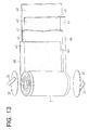
- Cylindrical lithium secondary cells of relatively large capacity for example, for use in electric motor vehicles comprise, as shown in FIGS. 11 and 12, a cylindrical cell can 1 having a cylinder 11 and lids 12, 12 welded to the respective ends of the cylinder, and a rolled-up electrode unit 4 encased in the can 1.
- a pair of positive and negative electrode terminal assemblies 9, 9 are attached to the lids 12, 12, respectively.
- the two electrodes of the rolled-up electrode unit 4 are connected to the terminal assemblies 9, 9, whereby the electric power generated by the electrode unit 4 can be delivered to an external device from the pair of terminal assemblies 9, 9.
- Each lid 12 is provided with a gas vent valve 13.
- the rolled-up electrode unit 4 comprises a positive electrode 41 and a negative electrode 43 which are each in the form of a strip and which are rolled up into a spiral form with a striplike separator 42 interposed between the electrodes.
- the positive electrode 41 comprises a striplike current collector foil 45 in the form of aluminum foil and coated over opposite surfaces thereof with a positive electrode active substance 44 comprising a lithium containing composite oxide.
- the negative electrode 43 comprises a striplike current collector foil 47 in the form of copper foil and coated over opposite surfaces thereof with a negative electrode active substance 46 containing a carbon material.
- the separator 42 is impregnated with a nonaqueous electrolyte.
- the positive electrode 41 and the negative electrode 43 are each superposed on the respective separators 42, as displaced from the separator widthwise thereof, and the assembly is rolled up into a spiral form, whereby the edge 48 of the current collector foil 45 of the positive electrode 41 is positioned as projected outward beyond the edge of the separator 42 at one of the axially opposite ends of the electrode unit 4, and the edge 48 of the current collector foil 47 of the negative electrode 43 is positioned as projected outward beyond the edge of the separator 42 at the other end of the unit 4.
- a current collecting plate 32 in the form of a disk is joined to each of the opposite ends of the electrode unit 4 by resistance welding and connected by a lead member 33 to the base end of the electrode terminal assembly 9 shown in FIG. 12.
- the electrode terminal assembly 9 comprises an electrode terminal 91 extending through a hole in the lid 12 of the can 1 and mounted on the lid 12.
- the electrode terminal 91 has a flange 92 at its base end.
- An insulating packing 93 is fitted in the hole of the lid 12 for electrically insulating the electrode terminal 91 from the lid 12 and providing a seal therebetween.
- the electrode terminal 91 has a washer 94 fitted therearound from outside the lid 12, and a first nut 95 and a second nut 96 screwed thereon.
- the first nut 95 is tightened up to clamp the insulating packing 93 between the flange 92 of the terminal 91 and the washer 94 and thereby seal off the hole more effectively.
- the outer end of the lead member 33 is fixedly joined to the flange 92 of the terminal 91 by spot welding or ultrasonic welding.
- the lithium secondary cell having the current collecting structure shown in FIG. 12 nevertheless has the problem that the edges 48, 48 of the current collector foils 45, 47 forming the positive electrode 41 and the negative electrode 43 of the rolled-up electrode unit 4 have a small area, which results in a small area of contact between each edge of the current collector foil and the corresponding current collecting plate 32, consequently increasing the internal resistance of the cell. Further when the outermost peripheral portion of the current collecting plate 32 is joined to the electrode edge positioned radially most outwardly of the electrode unit 4 by laser welding, the laser beam is likely to leak out from the collecting plate 32 to irradiate the electrode or separator, causing damage to the electrode or separator.
- a cylindrical secondary cell of improved power characteristics which, as seen in FIG. 17, comprises a positive electrode 81 having an uncoated portion which extends upward beyond a portion thereof coated with an active substance 84 and varies in width longitudinally of the electrode, and a negative electrode 82 having an uncoated portion which extends downward beyond a portion thereof coated with an active substance 85 and varies in width longitudinally of the electrode.
- the positive and negative electrodes 81, 82 are rolled up into a spiral form with a separator 83 interposed between the electrodes to obtain a rolled-up electrode unit 8 having conical projections 86 as seen in FIG. 18.
- the electrode unit 8 is encased in a cell can 1.
- Each of the electrode projections 86 is connected to an electrode terminal 90 by a current collecting lead 80 (JP-A No. 329398/1998).
- the secondary cell described requires the step of obliquely cutting an edge of each of the positive and negative electrodes 81, 82 as shown in FIG. 17. This not only makes the fabrication process complex but also presents difficulty in giving an accurately finished conical surface to the projection 86 of the rolled-up electrode unit 8 as shown in FIG. 18 by rolling up the assembly of the two electrodes, consequently entailing the problem of an impaired yield and variations in the properties of cells.
- a manufacturing cost reduction requires a current collecting structure of high productivity.
- a nonaqueous electrolyte secondary cell having low resistance and excellent in productivity which has a current collecting plate 7 of the shape shown in FIG. 27 (JP-B No. 4102/1990).
- the collecting plate 7 has a central hole 74 and a lead portion 75 extending from the outer periphery thereof.
- the collecting plate 7 further has a plurality of ridges 72 V-shaped in cross section and extending radially from its center. As shown in FIG. 28, these ridges 72 are pressed against and weld to edge portions 48 of electrode of a rolled-up electrode unit 4.
- the ridges 72 of the collecting plate 7 bite in the edge portions 48 of electrode of the electrode unit 4.
- the collecting plate is therefore in contact with the edge 48 of the electrode over a greater area than the conventional collecting plate which is in the form of a flat plate. This results in an increase in the quantity of current collected to afford an increased cell power.
- the ridges of the collecting plate have a V-shaped cross section with an acute angle, the area of contact of the ridges with the edge of the current collector foil is not sufficiently great. Accordingly, the collecting plate not only has great contact resistance at the weld but is also poor in the state of contact at the portions other than the weld. Thus, the structure described has the problem of low current collecting performance. Moreover, the junction between the V-shaped ridge and the edge of the current collector foil to be irradiated with a laser beam makes an acute angle with the direction of projection of the beam, so that the laser beam fails to act effectively on the junction for welding and is likely to produce a faulty weld joint.
- the nonaqueous electrolyte secondary cell to give an improved power, it is effective to reduce the electric resistance of the path through which the electric power produced by the rolled-up electrode unit 4 is delivered to the outside, i.e., the internal resistance, whereas the current collecting plate 7 shown in FIG. 27 is greater in the average distance over which the current collected by the plate 7 flows before flowing into the lead portion 75 because the lead portion 75 extends from the outer periphery of the plate 7. For this reason, the secondary cell incorporating the collecting plate 7 still has great internal resistance.
- a first object of the present invention is to provide a nonaqueous electrolyte secondary cell having a current collecting structure wherein even when the current collectors forming the electrode unit are very thin, the current collector edge is held in satisfactory contact with a current collecting plate to ensure high current collecting performance and which is excellent also in productivity.
- a second object of the present invention is to provide a cylindrical secondary cell of the tabless type wherein a current collecting plate can be welded to the end of a rolled-up electrode unit without the likelihood of causing damage to the electrode or the separator and which can be fabricated by a simple process, the cell further exhibiting excellent power characteristics.
- a third object of the present invention is to provide a nonaqueous electrolyte secondary cell which has a current collecting structure comprising a current collecting plate and which is smaller than conventionally in internal resistance.
- the present invention provides a nonaqueous electrolyte secondary cell wherein a current collector forming a positive electrode 41 or a negative electrode 43 has an edge 48 projecting from at least one of opposite ends of a rolled-up electrode unit 4, the current collector edge 48 being covered with a current collecting plate 5.
- the current collecting plate 5 has a plurality of circular-arc protrusions 52 projecting in a circular-arc cross section toward the current collector edge 48 and a plurality of slit pieces cut to a raised form toward the current collector edge 48, the circular-arc protrusions 52 being welded to the current collector edge 48 while biting into the current collector edge 48 along with the slit pieces 53.
- the current collecting plate 5 is connected to one of a pair of electrode terminal portions.
- the current collecting plate 5 is pressed against the current collector edge 48 of the rolled-up electrode unit 4, whereby each circular-arc protrusion 52 is caused to bite into the current collector edge 48, forming on the current collector edge 48 a cylindrical junction shaped in conformity with the shape of surface of the protrusion 52.
- the junction has a large area than when the protrusion is V-shaped in cross section.
- the slit pieces 53 also bite deep into the current collector edge 48, resulting in a satisfactory state of contact between the collecting plate 5 and the current collector edge 48 at regions other than the welds.
- the collecting plate 5 can be joined to the current collector edge 48 over increased areas of contact by irradiating the junctions of the circular-arc protrusions 52 and the current collector edge 48 with a laser beam or electron beam and thereby welding the collecting plate 5 to the current collector edge 48. This results in reduced contact resistance and high current collecting performance.
- each protrusion 52 of the current collecting plate 5 and the current collector edge 48 has its central portion positioned at an angle of 90 degrees or an angle approximate thereto with the direction of projection of the beam. This permits the laser beam or electron beam to act effectively on the junction for welding, whereby a high weld strength is available due to an increased joint area.
- the current collecting plate 5 comprises a disklike body 51 having the circular-arc protrusions 52 and the slit pieces 53 formed radially and opposed to the current collector edge 48, and a striplike lead portion 55 extending from an edge portion of the disklike body 51 and joined at an outer end thereof to the electrode terminal portion.
- the current produced by the rolled-up electrode unit 4 is collected by the collecting plate 5 and flows to the electrode terminal portion via the lead portion 55.
- each of the slit pieces 53 is in contact with the current collector edge 48 over a length at least 0.5 times the radius of the current collecting plate 5. This provides a sufficiently wide area of contact between the current collecting plate 5 and the current collector edge 48 for high current collecting performance.
- Each of the slit pieces 53 projects toward the current collector edge 48 over a length at least 1.0 times to not greater than 1.5 times the length of projection of the circular-arc protrusion 52. This enables the protrusion 52 to come into contact with the current collector edge 48 over a wide area, while the slit piece 53 bites into the current collector edge 48 to a sufficient depth.
- the current collecting plate 5 can be made from Cu, Al, Ni, SUS, Ti or an alloy of such metals.
- the cell thus provided is excellent in corrosion resistance to the nonaqueous electrolyte and in electric conductivity.
- the rolled-up electrode unit of the cell of the invention comprises a very thin current collector, the current collector edge can be held in contact with the collecting plate over increased areas, while the cell can be provided with high productivity.
- the present invention provides a cylindrical secondary cell comprising a positive electrode 41 and a negative electrode 43 each in the form of a strip and rolled up into a spiral form with a separator 42 interposed between the electrodes and impregnated with a nonaqueous electrolyte to obtain a rolled-up electrode unit 4, and a cylindrical cell can 1 having the rolled-up electrode unit 4 accommodated therein, the cell being adapted to deliver electric power generated by the rolled-up electrode unit 4 to the outside via a pair of electrode terminal portions.
- the positive electrode 41 and the negative electrode 43 each comprise a striplike current collector and an active substance coating the current collector, each of the electrodes having a portion coated with the active substance and extending longitudinally of the current collector, and an uncoated portion not coated with the active substance and formed along an edge of the current collector.
- the uncoated portion projects from at least one of axially opposite ends of the rolled-up electrode unit 4 to provide a cylindrical projection 40, which is covered with a current collecting plate 6 made of a metal.
- the current collecting plate 6 comprises a top plate 61 in contact with an end face of the cylindrical projection 40 and a skirt portion 62 in contact with at least a portion of an outer peripheral surface of the cylindrical projection 40.
- the current collecting plate 6 is connected to one of the electrode terminal portions by a lead member 63.
- the end face of the cylindrical projection 40 of the rolled-up electrode unit 4 and the inner surface of the top plate 61 of the current collecting plate 6 are in contact with each other, and the outer peripheral surface of the cylindrical projection 40 and the inner peripheral surface of the skirt portion 62 of the collecting plate 6 are also in contact with each other, with the result that the contact resistance between the electrode of the unit 4 and the collecting plate 6 is low, consequently giving reduced internal resistance to the cell and permitting the cell to exhibit high power characteristics.
- the outer peripheral surface of the cylindrical projection 40 is covered with the skirt portion 62 of the collecting plate 6.
- the skirt portion therefore obviates the likelihood that the electrode or separator will be exposed directly to the laser beam, preventing damage to the electrode or separator.
- the positive electrode 41 and the negative electrode 43 forming the electrode unit 4 need only to be made each in the form of a strip having a specified width. This simplifies the fabrication process, further making it possible to give the cylindrical projection 40 of the unit 4 with an accurately finished cylindrical surface and consequently eliminating a reduction in the yield and variations in the cell performance.
- top plate 61 and the skirt portion 62 of the current collecting plate 6 are joined respectively to the end face and the outer peripheral surface of the cylindrical projection 40 of the rolled-up electrode unit 4 by laser welding. This fully reduces the contact resistance between the electrode unit 4 and the collecting plate 6.
- the current collecting plate can be welded to the rolled-up electrode unit without the likelihood of causing damage to the electrode or separator, so that the cylindrical secondary cell of the invention is easy to fabricate. Moreover, the reduced internal resistance of the cell assures outstanding power characteristics.
- the present invention further provides a nonaqueous electrolyte secondary cell comprising an electrode unit encased in a cell can, the electrode unit comprising as superposed in layers a pair of positive and negative electrodes and a separator interposed between the electrodes and impregnated with a nonaqueous electrolyte, the cell being adapted to deliver electric power generated by the electrode unit to the outside via a pair of electrode terminal portions provided respectively at opposite ends of the cell can, the nonaqueous electrolyte secondary cell being characterized in that an edge of a current collector forming the electrode projects from at least one of opposite ends of the electrode unit, a current collecting plate being joined to the edge and having a male screw projecting from a surface of the plate toward the electrode terminal portion, the male screw being in screwthread engagement with an internally threaded portion formed in the electrode terminal portion.
- the male screw provided on the surface of the current collecting plate is driven directly in the electrode terminal portion, forming the shortest current path between the current collecting plate and the terminal portion and consequently reducing the internal resistance of the cell.
- the male screw is integral with the current collecting plate.
- This structure has no joint between the collecting plate and the male screw and no contact resistance, consequently reducing the internal resistance of the cell.
- a base plate is provided on the surface of the current collecting plate centrally thereof, and the male screw is provided on a surface of the base plate.
- the base plate provided with the male screw is a member separate from the collecting plate, and can therefore be made from a material of low resistance different from the material of the collecting plate.
- the opposite ends of the electrode unit have edges of current collectors forming the respective electrodes projecting therefrom, and the current collector edges have respective current collecting plates joined thereto, the male screw projecting from one of the current collecting plates, the other current collecting plate being provided with a connecting member projecting therefrom and having elasticity so as to move toward or away from the electrode terminal portion.
- the connecting member having elasticity is provided between the electrode terminal portion and the current collecting plate at one end of the electrode unit, so that the errors involved in assembling the electrode unit or the cell can is absorbable by the elastic deformation of the connecting member. This eliminates the need for strict dimensional management, leading to an improved cell production efficiency.
- the nonaqueous electrolyte secondary cell provided by the invention has lower internal resistance than conventionally.
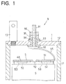
- the lithium secondary cell of the invention comprises a cylindrical cell can 1 having a cylinder 11 and lids 12, 12 welded to the respective ends thereof, and a rolled-up electrode unit 4 encased in the can 1.
- a pair of positive and negative electrode terminal assemblies 9, 9 are attached to the lids 12, 12, respectively.
- the terminal assembly 9 has the same construction as in the prior art.
- Each lid 12 is provided with a gas vent valve 13.
- a current collecting plate 5 is provided at each end of the electrode unit 4 and joined to the edge 48 of a current collector foil by laser welding.
- a lead portion 55 projecting from an end portion of the collecting plate 5 is welded at its outer end to a flange 92 of an electrode terminal 91 constituting the electrode terminal assembly 9 by spot welding, ultrasonic welding or laser welding.
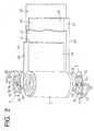
- the rolled-up electrode unit 4 comprises a positive electrode 41 and a negative electrode 43 which are each in the form of a strip and which are rolled up into a spiral form with a striplike separator 42 interposed between the electrodes.
- the positive electrode 41 comprises a striplike current collector foil 45 in the form of aluminum foil and coated over opposite surfaces thereof with a positive electrode active substance 44 comprising a lithium containing composite oxide.
- the negative electrode 43 comprises a striplike current collector foil 47 in the form of copper foil and coated over opposite surfaces thereof with a negative electrode active substance 46 containing a carbon material.
- the separator 42 is impregnated with a nonaqueous electrolyte.
- the positive electrode 41 has a portion coated with the positive electrode active substance 44 and a portion not coated with the substance.
- the negative electrode 43 has a portion coated with the negative electrode active substance 46 and a portion not coated with the substance.
- the positive electrode 41 and the negative electrode 43 are superposed on respective separators 42, as displaced from the separator widthwise thereof, and the uncoated portions of the positive electrode 41 and the negative electrode 43 are caused to project outward beyond the opposite edges of the separator 42.
- the assembly is then rolled up into a spiral form, whereby the electrode unit 4 is fabricated.
- An edge 48 of a current collector foil of the uncoated portion of the positive electrode 41 extends outward beyond one edge of the separator 42 at one of the axially opposite ends of the electrode unit 4, while an edge 48 of a current collector foil of the uncoated portion of the negative electrode 43 extends outward beyond the other edge of the separator 42 at the other end of the unit 4.
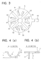
- the current collecting plate 5 comprises a disklike body 51 having a central hole 54.
- the body 51 is integrally provided with a plurality of (four, according to the embodiment) circular-arc protrusions 52 extending radially, arranged about the central hole 54 and projecting toward the rolled-up electrode unit 4.
- a plurality of (two, according to the embodiment) slit pieces 53 are formed on the body 51 between each pair of circular-arc protrusions 52, 52 to project toward the electrode unit 4.
- a lead portion 55 in the form of a strip is integral with an end portion of the body 51.
- the protrusion 52 of the collecting plate 5 is circular-arc, i.e., semicircular, in cross section orthogonal to a radial line of the body 51.
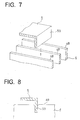
- each slit piece 53 of the collecting plate 5 bites deep into the edge 48 of the current collector foil of the unit 4 in pressing contact therewith as shown in FIG. 8.
- a laser beam is projected onto the inner surface of the protrusion 52 of the collecting plate 5 for laser welding as indicated by arrows in FIG. 6. Consequently, the protrusion 52 of the collecting plate 5 and the edge 48 of the current collector foil of the electrode unit 4 are joined to each other over a large area of contact, with each slit piece 53 held in pressing contact with the edge 48 of the current collector foil as seen in FIG. 8.
- the current collecting plate 5 is joined to the edge 48 of the current collector foil over a large area of contact by the weld of each circular-arc protrusion 52 and the edge 48 of the current collector foil, with each slit piece 53 biting into the edge 48 of the current collector foil in a region other than the weld to ensure satisfactory contact. This reduces the resistance of contact between the collecting plate 5 and the rolled-up electrode unit 4. Moreover, the plurality of slit pieces 53 formed in the collecting plate 5 collect current over the entire area of the edge 48 of the current collector foil to achieve high current collection performance.
- the junction of the protrusion 52 of the collecting plate 5 and the edge of the current collector foil has its central portion positioned at an angle of 90 degrees or an angle approximate thereto with the direction of projection of the laser beam, thereby permitting the laser beam to act effectively on the junction for welding and consequently giving a high weld strength due to an increased joint area.
- Cells A to P of the invention and comparative cell Q were prepared in the following manner.
- a rolled-up electrode unit 4 was prepared by arranging in superposed layers a positive electrode 41 obtained by coating an aluminum current collector foil 45 having a thickness of 20 ⁇ m with a positive electrode active substance 44 comprising LiCoO 2 , a negative electrode 43 obtained by coating a copper current collector foil 47 having a thickness of 20 ⁇ m with a negative electrode active substance 46 comprising graphite and separators 42 in the form of an ion-permeable finely porous membrane of polypropylene, and rolling up these components into a spiral form as shown in FIG. 2.
- the positive electrode 41 and the negative electrode 43 each had an uncoated portion of predetermined width at a widthwise end thereof.
- a current collecting plate 5 of aluminum was prepared which comprised a disklike body 51 having a radius of 28 mm, a thickness of 1 mm, a plurality of circular-arc protrusions 52 formed radially therein, and a plurality of slit pieces 53 formed radially thereon.
- the collecting plate 5 was fitted over the edge 48 of the positive electrode current collector foil of the electrode unit 4 and pressed thereagainst with a jig from above.
- the circular-arc protrusions 52 of the collecting plate 5 shown in FIGS. 3 and 4(a) were 1 mm in wall thickness T and 1.4 mm in inside radius R (i.e., the length X of projection from the disklike body rear surface).
- the slit pieces 53 shown in FIGS. 3 and 4(b) were 14 mm in the length L of contact thereof with the edge 48 of the current collector foil and 2.1 mm in the length Y of projection from the disklike body rear surface.
- a current collecting structure for the positive electrode was then made by joining the outer end of an aluminum lead to the rear face of an aluminum electrode terminal by laser welding.
- a negative electrode current collecting structure was prepared in the same manner as above except that the electrode terminal, current collecting plate and lead piece used were made from nickel.
- the rolled-up electrode unit 4 was thereafter encased in a cylinder 11, and a lid 12 having an electrode terminal assembly 9 mounted thereon is fixedly welded to each open end of the cylinder 11.
- An ester-type organic electrolyte was subsequently placed into the cylinder, i.e., can 1, to fabricate invention cell A having a rated electric power capacity of 180 Wh.
- Cells B to J of the invention were prepared in the same manner as invention cell A except that the slit pieces 53 of the current collecting plate 5 had a length (contact length L) of 9 mm, 11 mm, 12 mm, 14 mm, 16 mm, 18 mm, 19 mm, 22 mm or 24 mm.
- invention cell E had the same construction as invention cell A.
- invention cells K-P were prepared in the same manner as invention cell A except that the slit pieces 53 of the current collecting plate 5 were 1.2 mm, 1.4 mm, 1.8 mm, 2.1 mm, 2.2 mm or 2.4 mm in length Y of projection.
- invention cell N had the same construction as invention cell A.
- Comparative cell Q was prepared in the same manner as invention cell A except that the current collecting plate 5 had circular-arc protrusions 52 only, with no slit pieces 53 formed.
- Invention cells A to P and comparative cell Q were tested for power characteristics as will be described below for the comparison of power characteristics.
- invention cell A and comparative cell Q were charged at 0.125 C to 4.1 V, then discharged at 0.5 C to a depth of discharge of 40% and thereafter checked for power characteristics at a current value of 4 C for a discharge period of 10 seconds.
- Table 1 shows the result.
- the power density was determined by calculating the power value based on the voltage-current characteristics under the above conditions and dividing the result by the weight of the cell. Power density [W/kg] Cell A (invention) 620 Cell Q (comparative) 594
- Table 1 reveals that invention cell A is higher than comparative cell Q in power characteristics. This is thought attributable to the slit pieces 53 provided on each current collecting plate 5 of invention cell A and serving to improve the state of contact between the collecting plate 5 and the edge 48 of the current collector foil of the rolled-up electrode unit 4 and result in a reduction in contact resistance.
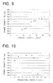
- FIG. 9 shows a graph prepared from the results of table 2.
- Table 2 and FIG. 9 reveal that the power density reduces markedly when the length L of contact between each slit piece 53 of the collecting plate 5 and the edge 48 of the current collector foil is smaller than 0.5 times (14 mm) the radius (28 mm) of the disklike body 51. This appears attributable to a reduced area of contact between the slit piece 53 and the edge of the current collector foil, markedly decreasing the effect to lower the resistance to current collection. Accordingly, it is desired that the slit pieces 53 of the collecting plate 5 have a contact length L at least 0.5 times the radius of the disklike body 51.
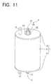
- FIG. 10 shows a graph prepared from the results of Table 3.
- Table 3 and FIG. 10 reveal that the power density decreases markedly if the projection length Y of each slit pieces 53 of the collecting plate 5 is greater than 1.5 times (2.1 mm) the projection length X (1.4 mm) of the circular-arc protrusion 52, because the excessively large projection length of the slit piece 53 prevents the circular-arc protrusion 52 from coming into full contact with the edge of the current collector foil to result in unsatisfactory laser welding joint and increased contact resistance.
- the power density decreases markedly if the projection length Y of each slit pieces 53 of the collecting plate 5 is smaller than 1.0 times (1.4 mm) the projection length X (1.4 mm) of the circular-arc protrusion 52.
- the reason is that the slit piece 53 fails to bite deep into the edge of the current collector foil because of too small a projection length, failing to ensure a fully improved state of contact between the collecting plate 5 and the edge 48 of the current collector foil. Accordingly it is desirable that the projection length Y of the slit pieces 53 of the collecting plate 5 be at least 1.0 times to not greater than 1.5 times the projection length X of the circular-arc protrusion 52.
- the cylindrical lithium secondary cell of the invention comprises a cylindrical can 1 having a cylinder 11 and lids 12, 12 welded to the respective ends thereof, and a rolled-up electrode unit 4 encased in the can 1.
- a pair of positive and negative electrode terminal assemblies 9, 9 are attached to the lids 12, 12, respectively.
- the terminal assembly 9 has the same construction as in the prior art.
- Each lid 12 is provided with a gas vent valve 13.
- a current collecting plate 6 is provided at each end of the electrode unit 4 and joined to a cylindrical projection 40 by laser welding.
- a lead member 63 has a base end joined to the upper surface of the collecting plate 6 by spot welding, and an outer end joined by spot welding to the rear face of a flange 92 of an electrode terminal 91 constituting the electrode terminal assembly 9.
- the rolled-up electrode unit 4 comprises a positive electrode 41 and a negative electrode 43 which are each in the form of a strip and which are rolled up into a spiral form with a striplike separator 42 interposed between the electrodes.
- the positive electrode 41 comprises a striplike current collector foil 45 in the form of aluminum foil and coated over opposite surfaces thereof with a positive electrode active substance 44 comprising a lithium containing composite oxides.
- the negative electrode 43 comprises a striplike current collector foil 47 in the form of copper foil and coated over opposite surfaces thereof with a negative electrode active substance 46 containing a carbon material.
- the separator 42 is impregnated with a nonaqueous electrolyte.
- the positive electrode 41 has a portion A coated with the positive electrode active substance 44 and a portion B not coated with the substance and extending along an edge 48 of a current collector foil.
- the negative electrode 43 has a portion A coated with the negative electrode active substance 46 and a portion B not coated with the substance and extending along an edge 48 of a current collector foil.
- the positive electrode 41 and the negative electrode 43 are superposed on respective separators 42, as displaced from the separators widthwise thereof, and the uncoated portions of the positive electrode 41 and the negative electrode 43 are caused to project outward beyond the opposite edges of the separator 42.
- the assembly is then rolled up into a spiral form, whereby the electrode unit 4 is fabricated.
- the edge 48 of the current collector foil of the uncoated portion of the positive electrode 41 extends outward beyond one edge of the separator 42 at one of the axially opposite ends of the electrode unit 4, providing the cylindrical projection 40 at the positive electrode side.
- the edge 48 of the current collector foil of the uncoated portion of the negative electrode 43 extends outward beyond the other edge of the separator 42 at the other end of the unit 4, providing the cylindrical projection 40 at the negative electrode side.
- the current collecting plate 6 comprises a disklike top plate 61 and a cylindrical skirt portion 62.
- the inner surface of the top plate 61 is in intimate contact with the outer end face of the cylindrical projection 40 and is joined thereto by laser welding, and the inner peripheral surface of the skirt portion 62 is in intimate contact with the outer peripheral surface of the projection 40 and is joined thereto by laser welding.
- the outer surface of the collecting plate 6 is connected by the lead member 63 to the flange 92 of the electrode terminal assembly 92.
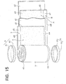
- a separator 42, negative electrode 43, separator 42 and positive electrode 41 are placed over one another in superposed layers first, and wound up into a spiral form to obtain the rolled-up electrode unit 4 as shown in FIG. 15.
- a current collecting plate 6 for the positive electrode is prepared from aluminum, while a negative electrode current collecting plate 6 is made from nickel.
- the cylindrical projections 40, 40 of the rolled-up electrode unit 4 are joined to the respective collecting plates 6 by laser welding.
- laser welding a laser beam is projected along radial paths on the surface of the top plate 61 of each collecting plate 6 as fitted over the projection 40 of the electrode unit 4, and on the outer peripheral surface of the skirt portion 62 of the plate 6 while making one turn around the periphery.
- a lead member 63 is joined at its base end to the surface of each collecting plate 6 by spot welding.
- the rolled-up electrode unit 4 is thereafter placed into the cylinder 11 of a cell can 1, and the outer end of the lead member 63 extending from each collecting plate 6 is spot-welded to the rear face of a flange 92 of an electrode terminal 91.
- An electrode terminal assembly 9 is attached to each of lids 12, and the first nut 95 is tightened up to give satisfactory liquid-tightness to the insulating packing 93.
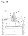
- Each lid 12 is then joined to the opening f the cylinder 11 by laser welding, an electrolyte is poured into the can 1, and a gas vent valve 13 is thereafter screwed into each lid 12 as shown in FIG. 14 for fixing, whereby a cylindrical lithium secondary cell of the invention is completed.
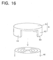
- a plurality of circular-arc pieces 64 may be provided on a disklike top plate 61 to form a skirt portion 62 as shown in FIG. 16 to obtain a current collecting plate 6.
- a positive electrode composition was prepared by mixing together a powder of LiCoO 2 serving as a positive electrode active substance and having a mean particle size of 5 ⁇ m and artificial graphite serving as an electrically conductive agent in a ratio by weight of 9:1. Next, polyvinylidene fluoride serving as a binder was dissolved in N-methyl-2-pyrrolidone (NMP) to prepare an NMP solution.
- NMP N-methyl-2-pyrrolidone
- compositions and the NMP solution were then mixed together so that the ratio of the composition to the polyvinylidene fluoride would be 95:5 by weight to prepare a slurry, which was then applied to opposite surfaces of aluminum foil serving as a positive electrode current collector foil and having a thickness of 20 ⁇ m with a doctor blade method, followed by drying in a vacuum at 150° C for 2 hours to prepare a positive electrode 41 shown in FIG. 15.
- Polyvinylidene fluoride serving as a binder was dissolved in NMP to prepare an NMP solution.
- the carbon powder and the NMP solution were then kneaded so that the ratio of the powder to the polyvinylidene fluoride would be 85:15 by weight to prepare a slurry, which was then applied to opposite surfaces of copper foil serving as a negative electrode current collector foil and having a thickness of 20 ⁇ m with a doctor blade method, followed by drying in a vacuum at 150° C for 2 hours to prepare a negative electrode 43 shown in FIG. 15.
- An electrolyte was prepared by dissolving LiPF 6 in an amount of 1 mol/L in a solvent obtained by mixing together ethylene carbonate and diethyl carbonate in a ratio by volume of 1:1.
- An ion-permeable finely porous membrane of polypropylene serving as a separator was wound around a spool with a diameter of 10 mm several turns, four sheets, i.e., a sheet of the separator, the positive electrode, a sheet of the separator and the negative electrode, as place one over another in superposed layers were wound up many turns into a spiral form so as to interpose the separator between the positive and negative electrodes, and the spool was finally remove to prepare a rolled-up electrode unit 4 shown in FIG. 15.
- a cylindrical lithium secondary cell of the invention was assembled using the electrode unit 4. The cell was 57 mm in outside diameter and 220 mm in length.
- Two kinds of current collecting plates 6 were prepared for use over the cylindrical projections 40 of the electrode unit 4: i.e., collecting plates 6 having a skirt portion 62 comprising two separate circular-arc pieces 64, 64 as shown in FIG. 16, and collecting plates 6 having a cylindrical skirt portion 62 as shown in FIG. 15.
- fabricated in the manner described above were invention cell 1 having the collecting plates 6 of FIG. 16, and invention cell 2 having the collecting plates 6 of FIG. 15.
- the skirt portion 62 of the plate 6 covered 30% of the entire area of the outer peripheral surface of the cylindrical projection 40.
- the skirt portion 62 of the collecting plate 6 covered 90% of the entire area of the outer peripheral surface of the cylindrical projection 40.
- a comparative cell was fabricated in the same manner as the invention cell described except that the disklike current collecting plates 32 shown in FIG. 13 were joined to the respective ends of the rolled-up electrode unit 4.
- Table 4 indicates that invention cells 1 and 2 are higher than the comparative cell in power density presumably because the current collecting plates 6 of the invention cells have the skirt portion 62 and are therefore improved in current collecting performance and reduced in internal resistance.
- invention cell 1 A comparison between invention cell 1 and invention cell 2 indicates that a greater power density is available when the skirt portion 62 of the current collecting plate 6 is in contact with the cylindrical projection 40 over a larger area. Thus, it is apparent that the skirt portion 62 of the collecting plate 6 contributes to an improvement in current collecting performance.
- the cylindrical lithium secondary cell of the invention is reduced in the contact resistance between each electrode of the rolled-up electrode unit 4 and the current collecting plate 6 to exhibit excellent power characteristics. Further in the laser welding step of joining the collecting plate 6 as fitted over the cylindrical projection 40 of the unit 4 in fabricating the secondary cell of the invention, the cylindrical projection 40 is almost entirely covered with the collecting plate 6, consequently eliminating the likelihood that the electrodes or separator will be exposed directly to the laser beam, whereby the damage to the electrodes or separator is avoidable.
- the positive electrode 41 and the negative electrode 43 constituting the rolled-up electrode unit 4 are each prepared in the form of a strip having a specified width, hence a simplified fabrication process.
- the cylindrical projection 40 of the electrode unit 4 can be given an accurately finished cylindrical surface by rolling up the two electrodes. This obviates the reduction of the yield or variations in the cell properties.
- Lithium secondary cells embodying the invention will further be described in detail with reference to the drawings concerned.
- the lithium secondary cell of this embodiment comprises a cylindrical can 1 having a cylinder 11 and lids 12, 12 welded to the respective ends thereof, and a rolled-up electrode unit 4 encased in the can 1.
- the lids 12, 12 have attached thereto a pair of positive and negative electrode terminal assemblies 9, 2 and gas vent valves 13, 13, respectively.
- the rolled-up electrode unit 4 has the same construction as the conventional one shown in FIG. 13, and comprises a positive electrode 41, separator 42 and negative electrode 43 each in the form of a strip.
- the positive electrode 41 and the negative electrode 43 are superposed on respective separators 42, as displaced from the separator widthwise thereof, whereby an edge 48 of the positive electrode 41 is caused to project outward beyond the corresponding edge of the separator 42 at one of the axially opposite ends of the electrode unit 4, and an edge 48 of the negative electrode 43 is caused to extend outward beyond the edge of the separator 42 at the other end of the unit 4.
- a pair of current collecting plates 105, 103 for the respective positive and negative electrodes are installed at the respective opposite ends of the electrode unit 4 and joined to the edges 48, 48 of the positive electrode 41 and the negative electrode 43.
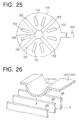
- the collecting plate 103 for the negative electrode has a central hole 134, a plurality of liquid inlets 133 and a plurality of protrusions 132 extending radially from the center of the plate and circular arc in cross section. As shown in FIG. 26, these protrusions 132 are pressed against and welded to the edge 48 of the negative electrode of the electrode unit 4.
- a threaded connector 20 is fixed to the center of the surface of the collecting plate 103.
- the threaded connector 20 comprises a cross plate 24 serving as a base plate, a disklike base 25 provided on the cross plate 24 centrally thereof, and a male screw 23 extending upright from the center of the base 25.
- a striplike lead portion 155 extends outward from the outer periphery of the collecting plate 105 for the positive electrode.
- the collecting plate 105 has a central hole 154, a plurality of liquid inlets 153 and a plurality of protrusions 152 extending radially from the center of the plate and circular arc in cross section. As shown in FIG. 26, these protrusions 152 are pressed against and welded to the edge 48 of the positive electrode of the electrode unit 4.
- the negative electrode terminal assembly 2 comprises an electrode terminal 21 in the form of a screw member and extending through and attached to the lid 12 of the cell can 1.
- the terminal 21 has a flange 21b formed at its base end.
- the electrode terminal 21 has an internally threaded portion 21a extending from the flange 21b toward the screw portion and having the male screw 23 screwed therein.
- a metal ring 22 is fitted around the base 25.
- the metal ring 22 has approximately the same outside diameter as the flange 21b of the terminal 21 and a hole 22a slightly greater than the base 25 in diameter. The metal ring 22 is held in intimate pressing contact with the flange 21b and the cross plate 24 by the male screw 23 screwed in the internally threaded portion 21a.
- the positive electrode terminal assembly 9 comprises an electrode terminal 91 in the form of a screw member and extending through and attached to the other lid 12 of the cell can 1.
- the terminal 91 has a flange 92 formed at its base end.
- a lead portion 155 joined to the collecting plate 105 for the positive electrode is folded over inwardly of the collecting plate 105 and has its outer end joined to the flange 92 of the electrode terminal 91.
- the lead portion 155 is curved like a bow and elastically deformable toward or away from the electrode terminal assembly 9.
- Insulating members 26, 93 of resin are fitted in the holes of the respective lids 12, 12 for the negative and positive electrodes for electrically insulating the electrode terminals 21, 91 from the lids 12, 12 and providing a seal therebetween.
- Each electrode terminal 21 (91) has a washer 27 (94) fitted therearound from outside the can 1, and a first nut 28 (95) and a second nut 29 (96) screwed thereon.
- the first nut 28 (95) is tightened up to clamp the insulating member 26 (93) between the flange 21b (92) of the terminal 21 (91) and the washer 27 (94) and thereby seal off the hole more effectively.
- the second nuts 29, 96 are used or connection to an external circuit.
- the male screw 23 is positioned on the negative electrode current collecting plate 103 centrally thereof as seen in FIG. 20, so that the average distance the current collected by the plate 103 flows to reach the male screw 23 is short. Further because the male screw 23 is screwed in the internally threaded portion 21a of the electrode terminal 21 for connection as shown in FIG. 19, the path of flow of the current from the collecting plate 103 to the electrode terminal 21 has a minimum length.
- cross plate 24, metal ring 22 and flange 21b are in intimate contact with one another to provide a current path of large cross sectional area as seen in FIG. 19, so that the current path has reduced electric resistance, consequently reducing the internal resistance of the cell.
- the lead portion 155 of the current collecting plate 105 for the positive electrode is elastically deformable as shown in FIG. 19 to absorb the errors involved in assembling the rolled-up electrode unit 4 or the cell can 1.
- the lithium secondary cell described is fabricated by the process to be described below.
- the current collecting plate 103 for the negative electrode shown in FIG. 20 is prepared from a nickel plate, and the collecting plate 105 for the positive electrode shown in FIG. 25 from an aluminum plate.
- the lead portion 155 is integral with the positive electrode collecting plate 105.
- the collecting plates 103, 105 are 20 mm in radius, 1.0 mm in thickness and 1.4 mm in the depth of the protrusions.
- the threaded connector 20 is made from nickel in the shape shown in FIGS. 20 and 21.
- the cross plate 24 is 1 mm in thickness
- the base 25 is 1 mm in thickness
- the male screw 23 is 6 mm in outside diameter and 9 mm in length.
- a current collector foil 45 in the form of a strip of aluminum foil is coated over the surface thereof with a positive electrode active substance 44 comprising a lithium containing composite oxides to prepare a positive electrode 41.
- a current collector foil 47 in the form of copper foil is coated over the surface thereof with a negative electrode active substance 46 containing carbon material to obtain a negative electrode 43.
- the positive electrode 41 and the negative electrode 43 are superposed on separators 42 as displaced widthwise thereof and wound up into a spiral form with the separator 42 interposed between the two electrodes to prepare a rolled-up electrode unit 4 as shown in FIG. 13.
- the protrusions 152 of the collecting plate 105 are joined to the edge 48 by laser welding, and the outer end of the lead portion 155 is joined to the flange 92 of the positive electrode terminal 91 by laser welding.
- the protrusions 132 of the collecting plate 103 are joined to the edge 48 by laser welding.
- the cross plate 24 of the threaded connector 20 is joined to the central portion of the collecting plate 103 by laser welding.
- the male screw 23 is driven into the internally threaded portion 21a, with the metal ring 22 fitted around the base 25 as seen in FIG. 19.
- the rolled-up electrode unit 4 is thereafter encased in a cylinder 11, a pair of positive and negative electrode terminals 91, 21 are inserted into lids 12, 12 with insulating members 93, 26 interposed therebetween, washers 94, 27 are fitted around the respective terminals 91, 21, and first nuts 95, 28 and second nuts 96, 29 are screwed on the respective terminals 91, 21, whereby a pair of positive and negative electrode terminal assemblies 9, 2 are mounted on the lids 12, 12.
- the lithium secondary cell of this embodiment has the same construction as the first embodiment except that the screw connector is made from copper.
- the cell is assembled in the same manner as the first embodiment.
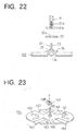
- the lithium secondary cell of this embodiment differs from the first embodiment in that a current collecting plate 106 for the negative electrode is integral with a male screw 165 as shown in FIGS. 23 and 24.
- the negative electrode current collecting plate 106 has a disklike base 166 formed on its surface centrally thereof and the male screw 165 which extends upright from the center of the base 166.
- a metal ring 167 shown in FIG. 23 is fitted around the base 166.
- the ring 167 has a hole 168 having a slightly larger diameter than the base 166, with the result that the ring 167 and the collecting plate 106 are held in intimate contact with each other.
- the lithium secondary cell of this embodiment has the same construction as the first embodiment with the exception of the above-mentioned feature, and is assembled in the same manner as the first embodiment.
- the cell of the present embodiment has no joint between the collecting plate 106 and the male screw 165, therefore has no contact resistance therebetween and is smaller in internal resistance.
- invention cell 1 of the foregoing first embodiment, invention cell of the second embodiment, and the comparative cells to be described below, i.e., comparative cells 1 and 2 were fabricated and checked for internal resistance.
- the cells were about 50 Wh in rated electric power capacity.
- Comparative cell 1 had the same construction as the first embodiment except that a current collecting plate made of nickel and shown in FIG. 25 was used for the negative electrode. The cell was assembled in the same manner as the first embodiment.
- Comparative cell 2 had the same construction as comparative cell 1 except that the current collecting plates for the positive and negative electrodes had protrusions which were V-shaped in cross section. The cell was assembled in the same manner as the first embodiment.
- the cells were checked for internal resistance by a resistance meter (a.c., 4 terminals, 1 kHz).
- Table 5 shows the internal resistance values of the cells measured.
- Cell Negative electrode Positive Electrode Internal Resistance (m ⁇ ) Invention cell 1 Male screw: Ni Collecting plate: Ni Protrusions: circular arc Collecting plate: Al Protrusions: circular arc 1.5 Invention cell 2
- the male screw is positioned at the center of the negative electrode current collecting plate, with the result that the average distance the current collected by the collecting plate flows before reaching the male screw is shorter. Further because the male screw is screwed in the internally threaded portion of the electrode terminal, the path of flow of the current from the collecting plate to the electrode terminal has a minimum length. Additionally, the metal ring having approximately the same outside diameter as the flange of the electrode terminal is in intimate contact with the flange and the cross plate to provide a current path of large cross sectional area.
- Invention cell 2 is especially small in internal resistance because the threaded connector therein is made from copper which is smaller in resistance than the nickel used for making the threaded connector of invention cell 1.
Abstract
Description
- The present invention relates to nonaqueous electrolyte secondary cells which comprise a can and a rolled-up electrode unit accommodated in the can and serving as a secondary cell element and which are adapted to deliver electric power generated by the electrode unit from a pair of electrode terminals provided on the can.
- In recent years, attention has been directed to lithium secondary cells or batteries having a high energy density for use as power sources for portable electronic devices, electric motor vehicles, etc. Cylindrical lithium secondary cells of relatively large capacity, for example, for use in electric motor vehicles comprise, as shown in FIGS. 11 and 12, a cylindrical cell can 1 having a
cylinder 11 andlids electrode unit 4 encased in thecan 1. A pair of positive and negativeelectrode terminal assemblies lids electrode unit 4 are connected to theterminal assemblies electrode unit 4 can be delivered to an external device from the pair ofterminal assemblies lid 12 is provided with agas vent valve 13. - As shown in FIG. 13, the rolled-up
electrode unit 4 comprises apositive electrode 41 and anegative electrode 43 which are each in the form of a strip and which are rolled up into a spiral form with astriplike separator 42 interposed between the electrodes. Thepositive electrode 41 comprises a striplikecurrent collector foil 45 in the form of aluminum foil and coated over opposite surfaces thereof with a positive electrodeactive substance 44 comprising a lithium containing composite oxide. Thenegative electrode 43 comprises a striplikecurrent collector foil 47 in the form of copper foil and coated over opposite surfaces thereof with a negative electrodeactive substance 46 containing a carbon material. Theseparator 42 is impregnated with a nonaqueous electrolyte. - The
positive electrode 41 and thenegative electrode 43 are each superposed on therespective separators 42, as displaced from the separator widthwise thereof, and the assembly is rolled up into a spiral form, whereby theedge 48 of thecurrent collector foil 45 of thepositive electrode 41 is positioned as projected outward beyond the edge of theseparator 42 at one of the axially opposite ends of theelectrode unit 4, and theedge 48 of thecurrent collector foil 47 of thenegative electrode 43 is positioned as projected outward beyond the edge of theseparator 42 at the other end of theunit 4. Acurrent collecting plate 32 in the form of a disk is joined to each of the opposite ends of theelectrode unit 4 by resistance welding and connected by alead member 33 to the base end of theelectrode terminal assembly 9 shown in FIG. 12. - The
electrode terminal assembly 9 comprises anelectrode terminal 91 extending through a hole in thelid 12 of thecan 1 and mounted on thelid 12. Theelectrode terminal 91 has aflange 92 at its base end. Aninsulating packing 93 is fitted in the hole of thelid 12 for electrically insulating theelectrode terminal 91 from thelid 12 and providing a seal therebetween. Theelectrode terminal 91 has awasher 94 fitted therearound from outside thelid 12, and afirst nut 95 and asecond nut 96 screwed thereon. Thefirst nut 95 is tightened up to clamp theinsulating packing 93 between theflange 92 of theterminal 91 and thewasher 94 and thereby seal off the hole more effectively. The outer end of thelead member 33 is fixedly joined to theflange 92 of theterminal 91 by spot welding or ultrasonic welding. - The lithium secondary cell having the current collecting structure shown in FIG. 12 nevertheless has the problem that the
edges current collector foils positive electrode 41 and thenegative electrode 43 of the rolled-upelectrode unit 4 have a small area, which results in a small area of contact between each edge of the current collector foil and the correspondingcurrent collecting plate 32, consequently increasing the internal resistance of the cell. Further when the outermost peripheral portion of thecurrent collecting plate 32 is joined to the electrode edge positioned radially most outwardly of theelectrode unit 4 by laser welding, the laser beam is likely to leak out from thecollecting plate 32 to irradiate the electrode or separator, causing damage to the electrode or separator. - A cylindrical secondary cell of improved power characteristics has been proposed which, as seen in FIG. 17, comprises a
positive electrode 81 having an uncoated portion which extends upward beyond a portion thereof coated with anactive substance 84 and varies in width longitudinally of the electrode, and anegative electrode 82 having an uncoated portion which extends downward beyond a portion thereof coated with anactive substance 85 and varies in width longitudinally of the electrode. The positive andnegative electrodes separator 83 interposed between the electrodes to obtain a rolled-up electrode unit 8 havingconical projections 86 as seen in FIG. 18. Theelectrode unit 8 is encased in a cell can 1. Each of theelectrode projections 86 is connected to anelectrode terminal 90 by a current collecting lead 80 (JP-A No. 329398/1998). - Although improved to some extent in power characteristics, the secondary cell described requires the step of obliquely cutting an edge of each of the positive and
negative electrodes projection 86 of the rolled-upelectrode unit 8 as shown in FIG. 18 by rolling up the assembly of the two electrodes, consequently entailing the problem of an impaired yield and variations in the properties of cells. Especially in the case of lithium secondary cells for use as power sources in electric motor vehicles, there is a need to reduce the internal resistance to the greatest possible extent so as to obtain a high capacity and a high power. Furthermore, a manufacturing cost reduction requires a current collecting structure of high productivity. - Accordingly, a nonaqueous electrolyte secondary cell having low resistance and excellent in productivity is proposed which has a
current collecting plate 7 of the shape shown in FIG. 27 (JP-B No. 4102/1990). Thecollecting plate 7 has acentral hole 74 and alead portion 75 extending from the outer periphery thereof. Thecollecting plate 7 further has a plurality of ridges 72 V-shaped in cross section and extending radially from its center. As shown in FIG. 28, theseridges 72 are pressed against and weld toedge portions 48 of electrode of a rolled-upelectrode unit 4. - With this cell, the
ridges 72 of thecollecting plate 7 bite in theedge portions 48 of electrode of theelectrode unit 4. The collecting plate is therefore in contact with theedge 48 of the electrode over a greater area than the conventional collecting plate which is in the form of a flat plate. This results in an increase in the quantity of current collected to afford an increased cell power. - However, since the ridges of the collecting plate have a V-shaped cross section with an acute angle, the area of contact of the ridges with the edge of the current collector foil is not sufficiently great. Accordingly, the collecting plate not only has great contact resistance at the weld but is also poor in the state of contact at the portions other than the weld. Thus, the structure described has the problem of low current collecting performance. Moreover, the junction between the V-shaped ridge and the edge of the current collector foil to be irradiated with a laser beam makes an acute angle with the direction of projection of the beam, so that the laser beam fails to act effectively on the junction for welding and is likely to produce a faulty weld joint.
- Further for the nonaqueous electrolyte secondary cell to give an improved power, it is effective to reduce the electric resistance of the path through which the electric power produced by the rolled-up
electrode unit 4 is delivered to the outside, i.e., the internal resistance, whereas thecurrent collecting plate 7 shown in FIG. 27 is greater in the average distance over which the current collected by theplate 7 flows before flowing into thelead portion 75 because thelead portion 75 extends from the outer periphery of theplate 7. For this reason, the secondary cell incorporating thecollecting plate 7 still has great internal resistance. - A first object of the present invention is to provide a nonaqueous electrolyte secondary cell having a current collecting structure wherein even when the current collectors forming the electrode unit are very thin, the current collector edge is held in satisfactory contact with a current collecting plate to ensure high current collecting performance and which is excellent also in productivity.
- A second object of the present invention is to provide a cylindrical secondary cell of the tabless type wherein a current collecting plate can be welded to the end of a rolled-up electrode unit without the likelihood of causing damage to the electrode or the separator and which can be fabricated by a simple process, the cell further exhibiting excellent power characteristics.
- A third object of the present invention is to provide a nonaqueous electrolyte secondary cell which has a current collecting structure comprising a current collecting plate and which is smaller than conventionally in internal resistance.
- The present invention provides a nonaqueous electrolyte secondary cell wherein a current collector forming a
positive electrode 41 or anegative electrode 43 has anedge 48 projecting from at least one of opposite ends of a rolled-upelectrode unit 4, thecurrent collector edge 48 being covered with acurrent collecting plate 5. - The
current collecting plate 5 has a plurality of circular-arc protrusions 52 projecting in a circular-arc cross section toward thecurrent collector edge 48 and a plurality of slit pieces cut to a raised form toward thecurrent collector edge 48, the circular-arc protrusions 52 being welded to thecurrent collector edge 48 while biting into thecurrent collector edge 48 along with theslit pieces 53. Thecurrent collecting plate 5 is connected to one of a pair of electrode terminal portions. - With the nonaqueous electrolyte secondary cell of the present invention, the
current collecting plate 5 is pressed against thecurrent collector edge 48 of the rolled-upelectrode unit 4, whereby each circular-arc protrusion 52 is caused to bite into thecurrent collector edge 48, forming on the current collector edge 48 a cylindrical junction shaped in conformity with the shape of surface of theprotrusion 52. The junction has a large area than when the protrusion is V-shaped in cross section. Theslit pieces 53 also bite deep into thecurrent collector edge 48, resulting in a satisfactory state of contact between thecollecting plate 5 and thecurrent collector edge 48 at regions other than the welds. - Accordingly, the
collecting plate 5 can be joined to thecurrent collector edge 48 over increased areas of contact by irradiating the junctions of the circular-arc protrusions 52 and thecurrent collector edge 48 with a laser beam or electron beam and thereby welding thecollecting plate 5 to thecurrent collector edge 48. This results in reduced contact resistance and high current collecting performance. - The junction of each
protrusion 52 of thecurrent collecting plate 5 and thecurrent collector edge 48 has its central portion positioned at an angle of 90 degrees or an angle approximate thereto with the direction of projection of the beam. This permits the laser beam or electron beam to act effectively on the junction for welding, whereby a high weld strength is available due to an increased joint area. - Stated more specifically, the
current collecting plate 5 comprises adisklike body 51 having the circular-arc protrusions 52 and theslit pieces 53 formed radially and opposed to thecurrent collector edge 48, and astriplike lead portion 55 extending from an edge portion of thedisklike body 51 and joined at an outer end thereof to the electrode terminal portion. In this specific construction, the current produced by the rolled-upelectrode unit 4 is collected by thecollecting plate 5 and flows to the electrode terminal portion via thelead portion 55. - Stated more specifically, each of the
slit pieces 53 is in contact with thecurrent collector edge 48 over a length at least 0.5 times the radius of thecurrent collecting plate 5. This provides a sufficiently wide area of contact between thecurrent collecting plate 5 and thecurrent collector edge 48 for high current collecting performance. - Each of the
slit pieces 53 projects toward thecurrent collector edge 48 over a length at least 1.0 times to not greater than 1.5 times the length of projection of the circular-arc protrusion 52. This enables theprotrusion 52 to come into contact with thecurrent collector edge 48 over a wide area, while theslit piece 53 bites into thecurrent collector edge 48 to a sufficient depth. - The
current collecting plate 5 can be made from Cu, Al, Ni, SUS, Ti or an alloy of such metals. The cell thus provided is excellent in corrosion resistance to the nonaqueous electrolyte and in electric conductivity. - Even when the rolled-up electrode unit of the cell of the invention comprises a very thin current collector, the current collector edge can be held in contact with the collecting plate over increased areas, while the cell can be provided with high productivity.
- The present invention provides a cylindrical secondary cell comprising a
positive electrode 41 and anegative electrode 43 each in the form of a strip and rolled up into a spiral form with aseparator 42 interposed between the electrodes and impregnated with a nonaqueous electrolyte to obtain a rolled-upelectrode unit 4, and a cylindrical cell can 1 having the rolled-upelectrode unit 4 accommodated therein, the cell being adapted to deliver electric power generated by the rolled-upelectrode unit 4 to the outside via a pair of electrode terminal portions. - The
positive electrode 41 and thenegative electrode 43 each comprise a striplike current collector and an active substance coating the current collector, each of the electrodes having a portion coated with the active substance and extending longitudinally of the current collector, and an uncoated portion not coated with the active substance and formed along an edge of the current collector. - The uncoated portion projects from at least one of axially opposite ends of the rolled-up
electrode unit 4 to provide acylindrical projection 40, which is covered with acurrent collecting plate 6 made of a metal. Thecurrent collecting plate 6 comprises atop plate 61 in contact with an end face of thecylindrical projection 40 and askirt portion 62 in contact with at least a portion of an outer peripheral surface of thecylindrical projection 40. Thecurrent collecting plate 6 is connected to one of the electrode terminal portions by alead member 63. - With the cylindrical secondary cell of the invention described, the end face of the
cylindrical projection 40 of the rolled-upelectrode unit 4 and the inner surface of thetop plate 61 of thecurrent collecting plate 6 are in contact with each other, and the outer peripheral surface of thecylindrical projection 40 and the inner peripheral surface of theskirt portion 62 of the collectingplate 6 are also in contact with each other, with the result that the contact resistance between the electrode of theunit 4 and the collectingplate 6 is low, consequently giving reduced internal resistance to the cell and permitting the cell to exhibit high power characteristics. - In joining the outermost peripheral portion of
top plate 61 of the collectingplate 6 to the portion of electrode edge positioned at the outermost peripheral portion of theelectrode unit 4 in the step of laser welding of the collectingplate 6 as fitted over thecylindrical projection 40 of theelectrode unit 4, the outer peripheral surface of thecylindrical projection 40 is covered with theskirt portion 62 of the collectingplate 6. The skirt portion therefore obviates the likelihood that the electrode or separator will be exposed directly to the laser beam, preventing damage to the electrode or separator. - Furthermore, the
positive electrode 41 and thenegative electrode 43 forming theelectrode unit 4 need only to be made each in the form of a strip having a specified width. This simplifies the fabrication process, further making it possible to give thecylindrical projection 40 of theunit 4 with an accurately finished cylindrical surface and consequently eliminating a reduction in the yield and variations in the cell performance. - Stated specifically, the
top plate 61 and theskirt portion 62 of thecurrent collecting plate 6 are joined respectively to the end face and the outer peripheral surface of thecylindrical projection 40 of the rolled-upelectrode unit 4 by laser welding. This fully reduces the contact resistance between theelectrode unit 4 and the collectingplate 6. - Thus, the current collecting plate can be welded to the rolled-up electrode unit without the likelihood of causing damage to the electrode or separator, so that the cylindrical secondary cell of the invention is easy to fabricate. Moreover, the reduced internal resistance of the cell assures outstanding power characteristics.
- The present invention further provides a nonaqueous electrolyte secondary cell comprising an electrode unit encased in a cell can, the electrode unit comprising as superposed in layers a pair of positive and negative electrodes and a separator interposed between the electrodes and impregnated with a nonaqueous electrolyte, the cell being adapted to deliver electric power generated by the electrode unit to the outside via a pair of electrode terminal portions provided respectively at opposite ends of the cell can, the nonaqueous electrolyte secondary cell being characterized in that an edge of a current collector forming the electrode projects from at least one of opposite ends of the electrode unit, a current collecting plate being joined to the edge and having a male screw projecting from a surface of the plate toward the electrode terminal portion, the male screw being in screwthread engagement with an internally threaded portion formed in the electrode terminal portion.
- With the nonaqueous electrolyte secondary cell of the invention described, the male screw provided on the surface of the current collecting plate is driven directly in the electrode terminal portion, forming the shortest current path between the current collecting plate and the terminal portion and consequently reducing the internal resistance of the cell.
- Stated more specifically, the male screw is integral with the current collecting plate. This structure has no joint between the collecting plate and the male screw and no contact resistance, consequently reducing the internal resistance of the cell.
- Alternatively, a base plate is provided on the surface of the current collecting plate centrally thereof, and the male screw is provided on a surface of the base plate. With this structure, the base plate provided with the male screw is a member separate from the collecting plate, and can therefore be made from a material of low resistance different from the material of the collecting plate. With the male screw positioned centrally of the collecting plate, the average distance the current collected by the collecting plate flows before reaching the male screw is short, consequently reducing the internal resistance of the cell.
- Further alternatively, the opposite ends of the electrode unit have edges of current collectors forming the respective electrodes projecting therefrom, and the current collector edges have respective current collecting plates joined thereto, the male screw projecting from one of the current collecting plates, the other current collecting plate being provided with a connecting member projecting therefrom and having elasticity so as to move toward or away from the electrode terminal portion. With this specific construction, the connecting member having elasticity is provided between the electrode terminal portion and the current collecting plate at one end of the electrode unit, so that the errors involved in assembling the electrode unit or the cell can is absorbable by the elastic deformation of the connecting member. This eliminates the need for strict dimensional management, leading to an improved cell production efficiency.
- Thus, the nonaqueous electrolyte secondary cell provided by the invention has lower internal resistance than conventionally.
-
- FIG. 1 is a fragmentary front view partly broken away and showing a cylindrical lithium secondary cell embodying the invention;
- FIG. 2 is an exploded perspective view of a rolled-up electrode unit and current collecting plates;
- FIG. 3 is a plan view of the current collecting plate;
- FIG. 4(a) is an enlarged view in section taken along the line A-A in FIG. 3;
- FIG. 4(b) is an enlarged view in section taken along the line B-B in FIG. 3;
- FIG. 5 is a perspective view showing the step of pressing a circular-arc protrusion of the collecting plate against the rolled-up electrode unit;
- FIG. 6 is a sectional view showing the circular-arc protrusion of the collecting plate biting into an edge of a current collector foil:
- FIG. 7 is a perspective view showing the step of pressing a slit piece of the collecting plate against the rolled-up electrode unit;
- FIG. 8 is a sectional view showing the slit piece of the collecting plate biting into an edge of a current collector foil:
- FIG. 9 is a graph showing the relationship between the contact length of slit piece of the collecting plate with the power density;
- FIG. 10 is a graph showing the relationship between the length of projection of the slit piece of the collecting plate with the power density;
- FIG. 11 is a perspective view showing the appearance of a cylindrical lithium secondary cell;
- FIG. 12 is a fragmentary front view partly broken away and showing a conventional lithium secondary cell;
- FIG. 13 is a perspective view partly in development of a rolled-up electrode unit for use in the cell;
- FIG. 14 is a front view partly broken away of a cylindrical lithium secondary cell embodying the invention;
- FIG. 15 is an exploded perspective view of a rolled-up electrode unit and current collecting plates incorporated into the cell;
- FIG. 16 is a perspective view of another example of current collecting plate;
- FIG. 17 is a development showing the positive electrode, separator and negative electrode of another conventional secondary cell;
- FIG. 18 is a fragmentary front view partly broken away and showing the secondary cell;
- FIG. 19 is a front view partly broken away and showing a nonaqueous electrolyte secondary cell of the invention;
- FIG. 20 is a perspective view of a current collecting plate used in the cell;
- FIG. 21 is a plan view of the collecting plate;
- FIG. 22 is an exploded view in section showing a structure for connecting the collecting plate to an electrode terminal assembly;
- FIG. 23 is a perspective view of a current collecting plate for use in another embodiment;
- FIG. 24 is a plan view of the collecting plate;
- FIG. 25 is a plan view of a positive electrode current collecting plate;
- FIG. 26 is a view showing the step of joining the protrusion of the collecting plate to an edge of electrode of the rolled-up electrode unit;
- FIG. 27 is a plan view of a conventional current collecting plate; and
- FIG. 28 is a view showing the step of joining a ridge of the conventional collecting plate to an edge of electrode of the rolled-up electrode unit.
-
- A lithium secondary cell embodying the invention will be described below in detail with reference to the drawings concerned.
- With reference to FIGS. 11 and 1, the lithium secondary cell of the invention comprises a cylindrical cell can 1 having a
cylinder 11 andlids electrode unit 4 encased in thecan 1. A pair of positive and negativeelectrode terminal assemblies lids terminal assembly 9 has the same construction as in the prior art. Eachlid 12 is provided with agas vent valve 13. - A
current collecting plate 5 is provided at each end of theelectrode unit 4 and joined to theedge 48 of a current collector foil by laser welding. Alead portion 55 projecting from an end portion of the collectingplate 5 is welded at its outer end to aflange 92 of anelectrode terminal 91 constituting theelectrode terminal assembly 9 by spot welding, ultrasonic welding or laser welding. - As shown in FIG. 2, the rolled-up
electrode unit 4 comprises apositive electrode 41 and anegative electrode 43 which are each in the form of a strip and which are rolled up into a spiral form with astriplike separator 42 interposed between the electrodes. Thepositive electrode 41 comprises a striplikecurrent collector foil 45 in the form of aluminum foil and coated over opposite surfaces thereof with a positive electrodeactive substance 44 comprising a lithium containing composite oxide. Thenegative electrode 43 comprises a striplikecurrent collector foil 47 in the form of copper foil and coated over opposite surfaces thereof with a negative electrodeactive substance 46 containing a carbon material. Theseparator 42 is impregnated with a nonaqueous electrolyte. - The
positive electrode 41 has a portion coated with the positive electrodeactive substance 44 and a portion not coated with the substance. Thenegative electrode 43 has a portion coated with the negative electrodeactive substance 46 and a portion not coated with the substance. - The
positive electrode 41 and thenegative electrode 43 are superposed onrespective separators 42, as displaced from the separator widthwise thereof, and the uncoated portions of thepositive electrode 41 and thenegative electrode 43 are caused to project outward beyond the opposite edges of theseparator 42. The assembly is then rolled up into a spiral form, whereby theelectrode unit 4 is fabricated. Anedge 48 of a current collector foil of the uncoated portion of thepositive electrode 41 extends outward beyond one edge of theseparator 42 at one of the axially opposite ends of theelectrode unit 4, while anedge 48 of a current collector foil of the uncoated portion of thenegative electrode 43 extends outward beyond the other edge of theseparator 42 at the other end of theunit 4. - With reference to FIGS. 2 to 4(b), the
current collecting plate 5 comprises adisklike body 51 having acentral hole 54. Thebody 51 is integrally provided with a plurality of (four, according to the embodiment) circular-arc protrusions 52 extending radially, arranged about thecentral hole 54 and projecting toward the rolled-upelectrode unit 4. A plurality of (two, according to the embodiment) slitpieces 53 are formed on thebody 51 between each pair of circular-arc protrusions electrode unit 4. Alead portion 55 in the form of a strip is integral with an end portion of thebody 51. As seen in FIG. 4(a), theprotrusion 52 of the collectingplate 5 is circular-arc, i.e., semicircular, in cross section orthogonal to a radial line of thebody 51. - Prepared first are a cell can 1 and
electrode terminal assemblies 9 which are shown in FIG. 1, a rolled-upelectrode unit 4 shown in FIG. 2, andcurrent collecting plates 5 which are shown in FIG. 3. The collectingplates 5 are then pressed against theedges 48 of the current collector foil at the respective ends of theelectrode unit 4 as shown in FIGS. 5 and 7. This forces each circular-arc protrusion 52 of the collectingplate 5 into theedge 48 of the current collector foil of theelectrode unit 4 as shown in FIG. 6, forming a cylindrical junction between theprotrusion 52 and theedge 48 of the current collector foil. - Further each
slit piece 53 of the collectingplate 5 bites deep into theedge 48 of the current collector foil of theunit 4 in pressing contact therewith as shown in FIG. 8. In this state, a laser beam is projected onto the inner surface of theprotrusion 52 of the collectingplate 5 for laser welding as indicated by arrows in FIG. 6. Consequently, theprotrusion 52 of the collectingplate 5 and theedge 48 of the current collector foil of theelectrode unit 4 are joined to each other over a large area of contact, with eachslit piece 53 held in pressing contact with theedge 48 of the current collector foil as seen in FIG. 8. - With the cylindrical lithium secondary cell described, the
current collecting plate 5 is joined to theedge 48 of the current collector foil over a large area of contact by the weld of each circular-arc protrusion 52 and theedge 48 of the current collector foil, with eachslit piece 53 biting into theedge 48 of the current collector foil in a region other than the weld to ensure satisfactory contact. This reduces the resistance of contact between the collectingplate 5 and the rolled-upelectrode unit 4. Moreover, the plurality ofslit pieces 53 formed in the collectingplate 5 collect current over the entire area of theedge 48 of the current collector foil to achieve high current collection performance. - The junction of the
protrusion 52 of the collectingplate 5 and the edge of the current collector foil has its central portion positioned at an angle of 90 degrees or an angle approximate thereto with the direction of projection of the laser beam, thereby permitting the laser beam to act effectively on the junction for welding and consequently giving a high weld strength due to an increased joint area. - Cells A to P of the invention and comparative cell Q were prepared in the following manner.
- For invention cell A, a rolled-up
electrode unit 4 was prepared by arranging in superposed layers apositive electrode 41 obtained by coating an aluminumcurrent collector foil 45 having a thickness of 20 µm with a positive electrodeactive substance 44 comprising LiCoO2, anegative electrode 43 obtained by coating a coppercurrent collector foil 47 having a thickness of 20 µm with a negative electrodeactive substance 46 comprising graphite andseparators 42 in the form of an ion-permeable finely porous membrane of polypropylene, and rolling up these components into a spiral form as shown in FIG. 2. Thepositive electrode 41 and thenegative electrode 43 each had an uncoated portion of predetermined width at a widthwise end thereof. - A
current collecting plate 5 of aluminum was prepared which comprised adisklike body 51 having a radius of 28 mm, a thickness of 1 mm, a plurality of circular-arc protrusions 52 formed radially therein, and a plurality ofslit pieces 53 formed radially thereon. The collectingplate 5 was fitted over theedge 48 of the positive electrode current collector foil of theelectrode unit 4 and pressed thereagainst with a jig from above. The circular-arc protrusions 52 of the collectingplate 5 shown in FIGS. 3 and 4(a) were 1 mm in wall thickness T and 1.4 mm in inside radius R (i.e., the length X of projection from the disklike body rear surface). Further theslit pieces 53 shown in FIGS. 3 and 4(b) were 14 mm in the length L of contact thereof with theedge 48 of the current collector foil and 2.1 mm in the length Y of projection from the disklike body rear surface. - In this state, a laser beam was projected onto the inner surface of each
protrusion 52 of theplate 5 as shown in FIG. 6 to weld the outer peripheral surface of theprotrusion 52 to theedge 48 of the current collector foil. A current collecting structure for the positive electrode was then made by joining the outer end of an aluminum lead to the rear face of an aluminum electrode terminal by laser welding. A negative electrode current collecting structure was prepared in the same manner as above except that the electrode terminal, current collecting plate and lead piece used were made from nickel. - The rolled-up
electrode unit 4 was thereafter encased in acylinder 11, and alid 12 having anelectrode terminal assembly 9 mounted thereon is fixedly welded to each open end of thecylinder 11. An ester-type organic electrolyte was subsequently placed into the cylinder, i.e., can 1, to fabricate invention cell A having a rated electric power capacity of 180 Wh. - Cells B to J of the invention were prepared in the same manner as invention cell A except that the
slit pieces 53 of thecurrent collecting plate 5 had a length (contact length L) of 9 mm, 11 mm, 12 mm, 14 mm, 16 mm, 18 mm, 19 mm, 22 mm or 24 mm. Incidentally, invention cell E had the same construction as invention cell A. - Invention cells K-P were prepared in the same manner as invention cell A except that the
slit pieces 53 of thecurrent collecting plate 5 were 1.2 mm, 1.4 mm, 1.8 mm, 2.1 mm, 2.2 mm or 2.4 mm in length Y of projection. Incidentally, invention cell N had the same construction as invention cell A. - Comparative cell Q was prepared in the same manner as invention cell A except that the
current collecting plate 5 had circular-arc protrusions 52 only, with noslit pieces 53 formed. - Invention cells A to P and comparative cell Q were tested for power characteristics as will be described below for the comparison of power characteristics.
- For an power characteristics test, invention cell A and comparative cell Q were charged at 0.125 C to 4.1 V, then discharged at 0.5 C to a depth of discharge of 40% and thereafter checked for power characteristics at a current value of 4 C for a discharge period of 10 seconds. Table 1 shows the result. The power density was determined by calculating the power value based on the voltage-current characteristics under the above conditions and dividing the result by the weight of the cell.
Power density [W/kg] Cell A (invention) 620 Cell Q (comparative) 594 - Table 1 reveals that invention cell A is higher than comparative cell Q in power characteristics. This is thought attributable to the
slit pieces 53 provided on eachcurrent collecting plate 5 of invention cell A and serving to improve the state of contact between the collectingplate 5 and theedge 48 of the current collector foil of the rolled-upelectrode unit 4 and result in a reduction in contact resistance. - Next, power characteristics of invention cells B to J were compared. Table 2 shows the results. FIG. 9 shows a graph prepared from the results of table 2.
Cell Length of contact [mm] Power density [W/kg] B 9 608 C 11 610 D 12 611 E(A) 14 620 F 16 624 G 18 626 H 19 627 I 22 631 J 24 631 - Table 2 and FIG. 9 reveal that the power density reduces markedly when the length L of contact between each
slit piece 53 of the collectingplate 5 and theedge 48 of the current collector foil is smaller than 0.5 times (14 mm) the radius (28 mm) of thedisklike body 51. This appears attributable to a reduced area of contact between theslit piece 53 and the edge of the current collector foil, markedly decreasing the effect to lower the resistance to current collection. Accordingly, it is desired that theslit pieces 53 of the collectingplate 5 have a contact length L at least 0.5 times the radius of thedisklike body 51. - The power characteristics of invention cells K to P were further compared. Table 3 shows the results. FIG. 10 shows a graph prepared from the results of Table 3.
Cell Projection length [mm] Power density [W/kg] K 1.2 616 L 1.4 619 M 1.8 620 N(A) 2.1 620 O 2.2 618 P 2.4 605 - Table 3 and FIG. 10 reveal that the power density decreases markedly if the projection length Y of each slit
pieces 53 of the collectingplate 5 is greater than 1.5 times (2.1 mm) the projection length X (1.4 mm) of the circular-arc protrusion 52, because the excessively large projection length of theslit piece 53 prevents the circular-arc protrusion 52 from coming into full contact with the edge of the current collector foil to result in unsatisfactory laser welding joint and increased contact resistance. - Further the power density decreases markedly if the projection length Y of each slit
pieces 53 of the collectingplate 5 is smaller than 1.0 times (1.4 mm) the projection length X (1.4 mm) of the circular-arc protrusion 52. The reason is that theslit piece 53 fails to bite deep into the edge of the current collector foil because of too small a projection length, failing to ensure a fully improved state of contact between the collectingplate 5 and theedge 48 of the current collector foil. Accordingly it is desirable that the projection length Y of theslit pieces 53 of the collectingplate 5 be at least 1.0 times to not greater than 1.5 times the projection length X of the circular-arc protrusion 52. - Incidentally, not only the
lead portion 55 shown in FIG. 1, but various other known structures are usable for connecting thecurrent collecting plate 5 to theelectrode terminal assembly 9. Although the laser beam is used for welding the collecting plate in the foregoing embodiment, the use of the beam is not limitative but an electron beam is also usable for welding. - A cylindrical lithium secondary cell embodying the invention will be described below in detail with reference to the drawings concerned.
- With reference to FIGS. 14, the cylindrical lithium secondary cell of the invention comprises a
cylindrical can 1 having acylinder 11 andlids electrode unit 4 encased in thecan 1. A pair of positive and negativeelectrode terminal assemblies lids terminal assembly 9 has the same construction as in the prior art. Eachlid 12 is provided with agas vent valve 13. - A
current collecting plate 6 is provided at each end of theelectrode unit 4 and joined to acylindrical projection 40 by laser welding. Alead member 63 has a base end joined to the upper surface of the collectingplate 6 by spot welding, and an outer end joined by spot welding to the rear face of aflange 92 of anelectrode terminal 91 constituting theelectrode terminal assembly 9. - As shown in FIG. 15, the rolled-up
electrode unit 4 comprises apositive electrode 41 and anegative electrode 43 which are each in the form of a strip and which are rolled up into a spiral form with astriplike separator 42 interposed between the electrodes. Thepositive electrode 41 comprises a striplikecurrent collector foil 45 in the form of aluminum foil and coated over opposite surfaces thereof with a positive electrodeactive substance 44 comprising a lithium containing composite oxides. Thenegative electrode 43 comprises a striplikecurrent collector foil 47 in the form of copper foil and coated over opposite surfaces thereof with a negative electrodeactive substance 46 containing a carbon material. Theseparator 42 is impregnated with a nonaqueous electrolyte. - The
positive electrode 41 has a portion A coated with the positive electrodeactive substance 44 and a portion B not coated with the substance and extending along anedge 48 of a current collector foil. Thenegative electrode 43 has a portion A coated with the negative electrodeactive substance 46 and a portion B not coated with the substance and extending along anedge 48 of a current collector foil. - The
positive electrode 41 and thenegative electrode 43 are superposed onrespective separators 42, as displaced from the separators widthwise thereof, and the uncoated portions of thepositive electrode 41 and thenegative electrode 43 are caused to project outward beyond the opposite edges of theseparator 42. The assembly is then rolled up into a spiral form, whereby theelectrode unit 4 is fabricated. Theedge 48 of the current collector foil of the uncoated portion of thepositive electrode 41 extends outward beyond one edge of theseparator 42 at one of the axially opposite ends of theelectrode unit 4, providing thecylindrical projection 40 at the positive electrode side. Theedge 48 of the current collector foil of the uncoated portion of thenegative electrode 43 extends outward beyond the other edge of theseparator 42 at the other end of theunit 4, providing thecylindrical projection 40 at the negative electrode side. - As shown in FIGS. 14 and 15, the
current collecting plate 6 comprises a diskliketop plate 61 and acylindrical skirt portion 62. The inner surface of thetop plate 61 is in intimate contact with the outer end face of thecylindrical projection 40 and is joined thereto by laser welding, and the inner peripheral surface of theskirt portion 62 is in intimate contact with the outer peripheral surface of theprojection 40 and is joined thereto by laser welding. The outer surface of the collectingplate 6 is connected by thelead member 63 to theflange 92 of theelectrode terminal assembly 92. - In fabricating the cylindrical lithium secondary cell of the present invention, a
separator 42,negative electrode 43,separator 42 andpositive electrode 41 are placed over one another in superposed layers first, and wound up into a spiral form to obtain the rolled-upelectrode unit 4 as shown in FIG. 15. Acurrent collecting plate 6 for the positive electrode is prepared from aluminum, while a negative electrodecurrent collecting plate 6 is made from nickel. - Next, the
cylindrical projections electrode unit 4 are joined to therespective collecting plates 6 by laser welding. For laser welding, a laser beam is projected along radial paths on the surface of thetop plate 61 of each collectingplate 6 as fitted over theprojection 40 of theelectrode unit 4, and on the outer peripheral surface of theskirt portion 62 of theplate 6 while making one turn around the periphery. Alead member 63 is joined at its base end to the surface of each collectingplate 6 by spot welding. - The rolled-up
electrode unit 4 is thereafter placed into thecylinder 11 of a cell can 1, and the outer end of thelead member 63 extending from each collectingplate 6 is spot-welded to the rear face of aflange 92 of anelectrode terminal 91. Anelectrode terminal assembly 9 is attached to each oflids 12, and thefirst nut 95 is tightened up to give satisfactory liquid-tightness to the insulatingpacking 93. - Each
lid 12 is then joined to the opening f thecylinder 11 by laser welding, an electrolyte is poured into thecan 1, and agas vent valve 13 is thereafter screwed into eachlid 12 as shown in FIG. 14 for fixing, whereby a cylindrical lithium secondary cell of the invention is completed. Alternatively, a plurality of circular-arc pieces 64 may be provided on a diskliketop plate 61 to form askirt portion 62 as shown in FIG. 16 to obtain acurrent collecting plate 6. - A positive electrode composition was prepared by mixing together a powder of LiCoO2 serving as a positive electrode active substance and having a mean particle size of 5 µm and artificial graphite serving as an electrically conductive agent in a ratio by weight of 9:1. Next, polyvinylidene fluoride serving as a binder was dissolved in N-methyl-2-pyrrolidone (NMP) to prepare an NMP solution. The composition and the NMP solution were then mixed together so that the ratio of the composition to the polyvinylidene fluoride would be 95:5 by weight to prepare a slurry, which was then applied to opposite surfaces of aluminum foil serving as a positive electrode current collector foil and having a thickness of 20 µm with a doctor blade method, followed by drying in a vacuum at 150° C for 2 hours to prepare a
positive electrode 41 shown in FIG. 15. - Carbon lumps (d002=3.356A; Lc>1000) were pulverized by forcing an air stream thereagainst to obtain a carbon powder. Polyvinylidene fluoride serving as a binder was dissolved in NMP to prepare an NMP solution. The carbon powder and the NMP solution were then kneaded so that the ratio of the powder to the polyvinylidene fluoride would be 85:15 by weight to prepare a slurry, which was then applied to opposite surfaces of copper foil serving as a negative electrode current collector foil and having a thickness of 20 µm with a doctor blade method, followed by drying in a vacuum at 150° C for 2 hours to prepare a
negative electrode 43 shown in FIG. 15. - An electrolyte was prepared by dissolving LiPF6 in an amount of 1 mol/L in a solvent obtained by mixing together ethylene carbonate and diethyl carbonate in a ratio by volume of 1:1.
- An ion-permeable finely porous membrane of polypropylene serving as a separator was wound around a spool with a diameter of 10 mm several turns, four sheets, i.e., a sheet of the separator, the positive electrode, a sheet of the separator and the negative electrode, as place one over another in superposed layers were wound up many turns into a spiral form so as to interpose the separator between the positive and negative electrodes, and the spool was finally remove to prepare a rolled-up
electrode unit 4 shown in FIG. 15. A cylindrical lithium secondary cell of the invention was assembled using theelectrode unit 4. The cell was 57 mm in outside diameter and 220 mm in length. - Two kinds of
current collecting plates 6 were prepared for use over thecylindrical projections 40 of the electrode unit 4: i.e., collectingplates 6 having askirt portion 62 comprising two separate circular-arc pieces plates 6 having acylindrical skirt portion 62 as shown in FIG. 15. Fabricated in the manner described above wereinvention cell 1 having the collectingplates 6 of FIG. 16, andinvention cell 2 having the collectingplates 6 of FIG. 15. Ininvention cell 1, theskirt portion 62 of theplate 6 covered 30% of the entire area of the outer peripheral surface of thecylindrical projection 40. Ininvention cell 2, theskirt portion 62 of the collectingplate 6 covered 90% of the entire area of the outer peripheral surface of thecylindrical projection 40. - A comparative cell was fabricated in the same manner as the invention cell described except that the disklike
current collecting plates 32 shown in FIG. 13 were joined to the respective ends of the rolled-upelectrode unit 4. -
Invention cells Cell Power density [W/kg] Invention cell 1645 Invention cell 2665 Comparative cell 590 - Table 4 indicates that
invention cells current collecting plates 6 of the invention cells have theskirt portion 62 and are therefore improved in current collecting performance and reduced in internal resistance. - A comparison between
invention cell 1 andinvention cell 2 indicates that a greater power density is available when theskirt portion 62 of thecurrent collecting plate 6 is in contact with thecylindrical projection 40 over a larger area. Thus, it is apparent that theskirt portion 62 of the collectingplate 6 contributes to an improvement in current collecting performance. - The cylindrical lithium secondary cell of the invention is reduced in the contact resistance between each electrode of the rolled-up
electrode unit 4 and thecurrent collecting plate 6 to exhibit excellent power characteristics. Further in the laser welding step of joining the collectingplate 6 as fitted over thecylindrical projection 40 of theunit 4 in fabricating the secondary cell of the invention, thecylindrical projection 40 is almost entirely covered with the collectingplate 6, consequently eliminating the likelihood that the electrodes or separator will be exposed directly to the laser beam, whereby the damage to the electrodes or separator is avoidable. - The
positive electrode 41 and thenegative electrode 43 constituting the rolled-upelectrode unit 4 are each prepared in the form of a strip having a specified width, hence a simplified fabrication process. Thecylindrical projection 40 of theelectrode unit 4 can be given an accurately finished cylindrical surface by rolling up the two electrodes. This obviates the reduction of the yield or variations in the cell properties. - Lithium secondary cells embodying the invention will further be described in detail with reference to the drawings concerned.
- With reference to FIG. 19, the lithium secondary cell of this embodiment comprises a
cylindrical can 1 having acylinder 11 andlids electrode unit 4 encased in thecan 1. Thelids electrode terminal assemblies gas vent valves - The rolled-up
electrode unit 4 has the same construction as the conventional one shown in FIG. 13, and comprises apositive electrode 41,separator 42 andnegative electrode 43 each in the form of a strip. Thepositive electrode 41 and thenegative electrode 43 are superposed onrespective separators 42, as displaced from the separator widthwise thereof, whereby anedge 48 of thepositive electrode 41 is caused to project outward beyond the corresponding edge of theseparator 42 at one of the axially opposite ends of theelectrode unit 4, and anedge 48 of thenegative electrode 43 is caused to extend outward beyond the edge of theseparator 42 at the other end of theunit 4. As shown in FIG. 19, a pair ofcurrent collecting plates electrode unit 4 and joined to theedges positive electrode 41 and thenegative electrode 43. - With reference to FIGS. 20 and 21, the collecting
plate 103 for the negative electrode has acentral hole 134, a plurality ofliquid inlets 133 and a plurality ofprotrusions 132 extending radially from the center of the plate and circular arc in cross section. As shown in FIG. 26, theseprotrusions 132 are pressed against and welded to theedge 48 of the negative electrode of theelectrode unit 4. - With reference to FIG. 20, a threaded
connector 20 is fixed to the center of the surface of the collectingplate 103. The threadedconnector 20 comprises across plate 24 serving as a base plate, adisklike base 25 provided on thecross plate 24 centrally thereof, and amale screw 23 extending upright from the center of thebase 25. - Referring to FIG. 25, a striplike
lead portion 155 extends outward from the outer periphery of the collectingplate 105 for the positive electrode. The collectingplate 105 has acentral hole 154, a plurality ofliquid inlets 153 and a plurality ofprotrusions 152 extending radially from the center of the plate and circular arc in cross section. As shown in FIG. 26, theseprotrusions 152 are pressed against and welded to theedge 48 of the positive electrode of theelectrode unit 4. - As shown in FIG. 19, the negative
electrode terminal assembly 2 comprises anelectrode terminal 21 in the form of a screw member and extending through and attached to thelid 12 of the cell can 1. The terminal 21 has aflange 21b formed at its base end. Theelectrode terminal 21 has an internally threadedportion 21a extending from theflange 21b toward the screw portion and having themale screw 23 screwed therein. Ametal ring 22 is fitted around thebase 25. As shown in FIG. 22, themetal ring 22 has approximately the same outside diameter as theflange 21b of the terminal 21 and ahole 22a slightly greater than the base 25 in diameter. Themetal ring 22 is held in intimate pressing contact with theflange 21b and thecross plate 24 by themale screw 23 screwed in the internally threadedportion 21a. - The positive
electrode terminal assembly 9 comprises anelectrode terminal 91 in the form of a screw member and extending through and attached to theother lid 12 of the cell can 1. The terminal 91 has aflange 92 formed at its base end. Alead portion 155 joined to the collectingplate 105 for the positive electrode is folded over inwardly of the collectingplate 105 and has its outer end joined to theflange 92 of theelectrode terminal 91. Thelead portion 155 is curved like a bow and elastically deformable toward or away from theelectrode terminal assembly 9. - Insulating
members respective lids electrode terminals lids can 1, and a first nut 28 (95) and a second nut 29 (96) screwed thereon. The first nut 28 (95) is tightened up to clamp the insulating member 26 (93) between theflange 21b (92) of the terminal 21 (91) and the washer 27 (94) and thereby seal off the hole more effectively. The second nuts 29, 96 are used or connection to an external circuit. Thus, the electric power generated by the rolled-upelectrode unit 4 can be delivered from the pair of positive and negativeelectrode terminal assemblies - With the nonaqueous electrolyte secondary cell of the present embodiment, the
male screw 23 is positioned on the negative electrodecurrent collecting plate 103 centrally thereof as seen in FIG. 20, so that the average distance the current collected by theplate 103 flows to reach themale screw 23 is short. Further because themale screw 23 is screwed in the internally threadedportion 21a of theelectrode terminal 21 for connection as shown in FIG. 19, the path of flow of the current from the collectingplate 103 to theelectrode terminal 21 has a minimum length. - Furthermore, the
cross plate 24,metal ring 22 andflange 21b are in intimate contact with one another to provide a current path of large cross sectional area as seen in FIG. 19, so that the current path has reduced electric resistance, consequently reducing the internal resistance of the cell. - Further the
lead portion 155 of thecurrent collecting plate 105 for the positive electrode is elastically deformable as shown in FIG. 19 to absorb the errors involved in assembling the rolled-upelectrode unit 4 or the cell can 1. - The lithium secondary cell described is fabricated by the process to be described below. First, the
current collecting plate 103 for the negative electrode shown in FIG. 20 is prepared from a nickel plate, and the collectingplate 105 for the positive electrode shown in FIG. 25 from an aluminum plate. Thelead portion 155 is integral with the positiveelectrode collecting plate 105. The collectingplates - The threaded
connector 20 is made from nickel in the shape shown in FIGS. 20 and 21. Thecross plate 24 is 1 mm in thickness, thebase 25 is 1 mm in thickness, and themale screw 23 is 6 mm in outside diameter and 9 mm in length. - Next, a
current collector foil 45 in the form of a strip of aluminum foil is coated over the surface thereof with a positive electrodeactive substance 44 comprising a lithium containing composite oxides to prepare apositive electrode 41. Acurrent collector foil 47 in the form of copper foil is coated over the surface thereof with a negative electrodeactive substance 46 containing carbon material to obtain anegative electrode 43. Thepositive electrode 41 and thenegative electrode 43 are superposed onseparators 42 as displaced widthwise thereof and wound up into a spiral form with theseparator 42 interposed between the two electrodes to prepare a rolled-upelectrode unit 4 as shown in FIG. 13. - Subsequently, with the collecting
plate 105 pressed against theedge 48 of the positive electrode of theelectrode unit 4 as shown in FIG. 26, theprotrusions 152 of the collectingplate 105 are joined to theedge 48 by laser welding, and the outer end of thelead portion 155 is joined to theflange 92 of thepositive electrode terminal 91 by laser welding. - Similarly, with the collecting
plate 103 pressed against theedge 48 of the negative electrode of theelectrode unit 4, theprotrusions 132 of the collectingplate 103 are joined to theedge 48 by laser welding. Further as seen in FIGS. 20 and 21, thecross plate 24 of the threadedconnector 20 is joined to the central portion of the collectingplate 103 by laser welding. Themale screw 23 is driven into the internally threadedportion 21a, with themetal ring 22 fitted around thebase 25 as seen in FIG. 19. - The rolled-up
electrode unit 4 is thereafter encased in acylinder 11, a pair of positive andnegative electrode terminals lids members washers respective terminals first nuts second nuts respective terminals electrode terminal assemblies lids - Finally the
lids cylinder 11, an electrolyte is placed into the cell can 1 through a mount hole for onegas vent valve 13, and thereafter thevalve 13 is screwed into the mount hole. In this way, a lithium secondary cell is completed according to the present embodiment. - The lithium secondary cell of this embodiment has the same construction as the first embodiment except that the screw connector is made from copper. The cell is assembled in the same manner as the first embodiment.
- The lithium secondary cell of this embodiment differs from the first embodiment in that a
current collecting plate 106 for the negative electrode is integral with amale screw 165 as shown in FIGS. 23 and 24. - The negative electrode
current collecting plate 106 has adisklike base 166 formed on its surface centrally thereof and themale screw 165 which extends upright from the center of thebase 166. Ametal ring 167 shown in FIG. 23 is fitted around thebase 166. Thering 167 has ahole 168 having a slightly larger diameter than the base 166, with the result that thering 167 and the collectingplate 106 are held in intimate contact with each other. The lithium secondary cell of this embodiment has the same construction as the first embodiment with the exception of the above-mentioned feature, and is assembled in the same manner as the first embodiment. - The cell of the present embodiment has no joint between the collecting
plate 106 and themale screw 165, therefore has no contact resistance therebetween and is smaller in internal resistance. -
Invention cell 1 of the foregoing first embodiment, invention cell of the second embodiment, and the comparative cells to be described below, i.e.,comparative cells -
Comparative cell 1 had the same construction as the first embodiment except that a current collecting plate made of nickel and shown in FIG. 25 was used for the negative electrode. The cell was assembled in the same manner as the first embodiment. -
Comparative cell 2 had the same construction ascomparative cell 1 except that the current collecting plates for the positive and negative electrodes had protrusions which were V-shaped in cross section. The cell was assembled in the same manner as the first embodiment. - The cells were checked for internal resistance by a resistance meter (a.c., 4 terminals, 1 kHz).
- Table 5 shows the internal resistance values of the cells measured.
Cell Negative electrode Positive Electrode Internal Resistance (mΩ) Invention cell 1Male screw: Ni Collecting plate: Ni Protrusions: circular arc Collecting plate: Al Protrusions: circular arc 1.5 Invention cell 2Male screw: Cu Collecting plate: Ni Protrusions: circular arc Collecting plate: Al Protrusions: circular arc 1.1 Comp. cell 1Collecting plate: Ni Protrusions: circular arc Collecting plate: Al Protrusions: circular arc 2.0 Comp. cell 2Collecting plate: Ni Protrusions; V-shaped Collecting plate: Al Protrusions: V-shaped 2.7 - The results given in Table 5 reveal that
invention cells - The reason is that with
invention cells -
Invention cell 2 is especially small in internal resistance because the threaded connector therein is made from copper which is smaller in resistance than the nickel used for making the threaded connector ofinvention cell 1. - The cells of the present invention are not limited to the foregoing embodiments in construction but can be modified variously by one skilled in the art without departing from the spirit of the invention as set forth in the appended claims.
Claims (4)
- A nonaqueous electrolyte secondary cell comprising an electrode unit encased in a cell can, the electrode unit comprising as superposed in layers a pair of positive and negative electrodes and a separator interposed between the electrodes and impregnated with a nonaqueous electrolyte, the cell being adapted to deliver electric power generated by the electrode unit to the outside via a pair of electrode terminal portions provided respectively at opposite ends of the cell can, the nonaqueous electrolyte secondary cell being characterized in that an edge of a current collector forming the electrode projects from at least one of opposite ends of the electrode unit, a current collecting plate being joined to the edge and having a male screw projecting from a surface of the plate toward the electrode terminal portion, the male screw being in screwthread engagement with an internally threaded portion formed in the electrode terminal portion.
- A nonaqueous electrolyte secondary cell according to claim 1, wherein the male screw is integral with the current collecting plate.
- A nonaqueous electrolyte secondary cell according to claim 1, wherein a base plate is provided on the surface of the current collecting plate centrally thereof, and the male screw is provided on a surface of the base plate.
- A nonaqueous electrolyte secondary cell according to claim 1, wherein the opposite ends of the electrode unit have edges of current collectors forming the respective electrodes projecting therefrom, and the current collector edges have respective current collecting plates joined thereto, the male screw projecting from one of the current collecting plates, the other current collecting plate being provided with a connecting member projecting therefrom and having elasticity so as to move toward or away from the electrode terminal portion, the connecting member being joined at an outer end thereof to the electrode terminal portion.
Applications Claiming Priority (7)
| Application Number | Priority Date | Filing Date | Title |
|---|---|---|---|
| JP2000070927A JP3738166B2 (en) | 2000-03-14 | 2000-03-14 | Non-aqueous electrolyte secondary battery |
| JP2000070927 | 2000-03-14 | ||
| JP2000292306 | 2000-09-26 | ||
| JP2000292306A JP3831595B2 (en) | 2000-09-26 | 2000-09-26 | Cylindrical secondary battery |
| JP2000362515 | 2000-11-29 | ||
| JP2000362515A JP3802338B2 (en) | 2000-11-29 | 2000-11-29 | Non-aqueous electrolyte secondary battery |
| EP01302226A EP1134819B1 (en) | 2000-03-14 | 2001-03-12 | Nonaqueous electrolyte secondary cells |
Related Parent Applications (1)
| Application Number | Title | Priority Date | Filing Date |
|---|---|---|---|
| EP01302226A Division EP1134819B1 (en) | 2000-03-14 | 2001-03-12 | Nonaqueous electrolyte secondary cells |
Publications (3)
| Publication Number | Publication Date |
|---|---|
| EP1596450A2 true EP1596450A2 (en) | 2005-11-16 |
| EP1596450A3 EP1596450A3 (en) | 2007-07-18 |
| EP1596450B1 EP1596450B1 (en) | 2009-04-29 |
Family
ID=27342664
Family Applications (3)
| Application Number | Title | Priority Date | Filing Date |
|---|---|---|---|
| EP05076328A Expired - Lifetime EP1610401B9 (en) | 2000-03-14 | 2001-03-12 | Nonaqueous electrolyte secondary cells |
| EP05076329A Expired - Lifetime EP1596450B1 (en) | 2000-03-14 | 2001-03-12 | Welded current collector plates in non-aqueous electrolyte secondary cells |
| EP01302226A Expired - Lifetime EP1134819B1 (en) | 2000-03-14 | 2001-03-12 | Nonaqueous electrolyte secondary cells |
Family Applications Before (1)
| Application Number | Title | Priority Date | Filing Date |
|---|---|---|---|
| EP05076328A Expired - Lifetime EP1610401B9 (en) | 2000-03-14 | 2001-03-12 | Nonaqueous electrolyte secondary cells |
Family Applications After (1)
| Application Number | Title | Priority Date | Filing Date |
|---|---|---|---|
| EP01302226A Expired - Lifetime EP1134819B1 (en) | 2000-03-14 | 2001-03-12 | Nonaqueous electrolyte secondary cells |
Country Status (7)
| Country | Link |
|---|---|
| US (1) | US6653017B2 (en) |
| EP (3) | EP1610401B9 (en) |
| KR (2) | KR100742496B1 (en) |
| CN (1) | CN1193451C (en) |
| AT (1) | ATE360893T1 (en) |
| CA (1) | CA2340482C (en) |
| DE (3) | DE60138577D1 (en) |
Cited By (1)
| Publication number | Priority date | Publication date | Assignee | Title |
|---|---|---|---|---|
| CN111788715A (en) * | 2018-01-09 | 2020-10-16 | 三星Sdi株式会社 | Secondary battery and method for manufacturing same |
Families Citing this family (57)
| Publication number | Priority date | Publication date | Assignee | Title |
|---|---|---|---|---|
| CN1172400C (en) * | 1999-08-10 | 2004-10-20 | 三洋电机株式会社 | Non-water electrolyte secondary battery and its mfg. method |
| US20040191926A1 (en) * | 2001-09-26 | 2004-09-30 | Zhong-Yin Zhang | Ptp1b inhibitors and ligands |
| US7070881B2 (en) * | 2001-10-18 | 2006-07-04 | Quallion Llc | Electrical battery assembly and method of manufacture |
| DE10159231A1 (en) | 2001-12-03 | 2003-06-18 | Nbt Gmbh | Galvanic element with winding electrode set |
| JP3935749B2 (en) * | 2002-03-13 | 2007-06-27 | 三洋電機株式会社 | Secondary battery |
| US20080163478A1 (en) * | 2003-08-18 | 2008-07-10 | Powergenix Systems, Inc. | Method for manufacturing nickel zinc batteries |
| EP1661195B1 (en) * | 2003-08-18 | 2016-01-13 | PowerGenix Systems, Inc. | Method of manufacturing nickel zinc batteries |
| US20060207084A1 (en) * | 2004-08-17 | 2006-09-21 | Powergenix, Inc. | Method of manufacturing nickel zinc batteries |
| JPWO2005052967A1 (en) * | 2003-11-25 | 2007-06-21 | 旭硝子株式会社 | Capacitor |
| KR100599598B1 (en) * | 2004-05-04 | 2006-07-13 | 삼성에스디아이 주식회사 | Secondary battery, electrodes assembly and plate using the same |
| KR100599752B1 (en) * | 2004-06-23 | 2006-07-12 | 삼성에스디아이 주식회사 | Secondary battery and electrodes assembly using the same |
| KR100863167B1 (en) * | 2004-07-20 | 2008-10-13 | 미쓰비시 가가꾸 가부시키가이샤 | Negative electrode material for lithium secondary battery, method for producing same, negative electrode for lithium secondary battery using same and lithium secondary battery |
| JP4606079B2 (en) * | 2004-07-21 | 2011-01-05 | 三洋電機株式会社 | battery |
| CN101010818B (en) * | 2004-07-28 | 2011-06-08 | 株式会社杰士汤浅 | Closed battery, its manufacturing method, battery pack composed of closed batteries, and its manufacturing method |
| KR100599802B1 (en) * | 2004-09-21 | 2006-07-12 | 삼성에스디아이 주식회사 | Secondary battery, electrodes assembly and plate using the same |
| KR100627360B1 (en) * | 2004-09-24 | 2006-09-21 | 삼성에스디아이 주식회사 | Plate used to collect current, secondary battery and module thereof |
| US20060073379A1 (en) * | 2004-10-05 | 2006-04-06 | Kim Sung-Min | Electric energy storage device and method of manufacturing the same |
| US8703330B2 (en) * | 2005-04-26 | 2014-04-22 | Powergenix Systems, Inc. | Nickel zinc battery design |
| KR20090012262A (en) * | 2006-05-09 | 2009-02-02 | 발렌스 테크놀로지, 인코포레이티드 | Secondary electrochemical cell with increased current collecting efficiency |
| US20090280406A1 (en) * | 2006-06-02 | 2009-11-12 | Kiyomi Kozuki | Secondary battery |
| KR100922352B1 (en) | 2007-10-02 | 2009-10-21 | 삼성에스디아이 주식회사 | Rechargeable battery |
| KR100882912B1 (en) * | 2007-10-15 | 2009-02-10 | 삼성에스디아이 주식회사 | Cap assembly, secondary battery therewith, manufacturing method of the cap assembly and manufacturing method of the secondary battery |
| JP2009110751A (en) * | 2007-10-29 | 2009-05-21 | Panasonic Corp | Secondary battery |
| JP5137530B2 (en) * | 2007-11-05 | 2013-02-06 | パナソニック株式会社 | Secondary battery and manufacturing method thereof |
| JP5132269B2 (en) * | 2007-11-13 | 2013-01-30 | 日立ビークルエナジー株式会社 | Lithium ion secondary battery |
| KR100923861B1 (en) * | 2008-02-11 | 2009-10-28 | 엘에스엠트론 주식회사 | Energy storing device |
| WO2009110250A1 (en) * | 2008-03-07 | 2009-09-11 | パナソニック株式会社 | Lithium-ion secondary battery and manufacturing method thereof |
| WO2009123888A1 (en) * | 2008-04-02 | 2009-10-08 | Powergenix Systems, Inc. | Cylindrical nickel-zinc cell with negative can |
| KR101023865B1 (en) * | 2009-02-25 | 2011-03-22 | 에스비리모티브 주식회사 | Rechargeable battery |
| KR101072956B1 (en) * | 2009-03-30 | 2011-10-12 | 에스비리모티브 주식회사 | Rechargeable battery |
| EP3499609B1 (en) | 2009-05-20 | 2023-11-22 | Clarios Advanced Solutions LLC | Lithium ion battery module |
| US20120270100A1 (en) * | 2009-07-29 | 2012-10-25 | Mike Yang | Secondary battery structure |
| JP5470142B2 (en) * | 2010-04-01 | 2014-04-16 | 日立ビークルエナジー株式会社 | Secondary battery and manufacturing method thereof |
| JP5862563B2 (en) | 2010-07-03 | 2016-02-16 | 株式会社Gsユアサ | Battery and battery manufacturing method |
| DE102010026093A1 (en) | 2010-07-05 | 2012-01-05 | Li-Tec Battery Gmbh | Galvanic cell |
| WO2012048652A1 (en) * | 2010-10-16 | 2012-04-19 | Byd Company Limited | Lithium-ion battery |
| KR101370858B1 (en) | 2011-04-26 | 2014-03-07 | 주식회사 엘지화학 | Bus Bar Having Projection and Battery Module Employed with the Same |
| DE102012213420A1 (en) * | 2012-07-31 | 2014-02-27 | Robert Bosch Gmbh | Method for producing a connection contact for an electrode of an electrochemical store, method for producing an electrochemical store and electrochemical store |
| US10790489B2 (en) | 2012-10-11 | 2020-09-29 | Cadenza Innovation, Inc. | Lithium ion battery |
| US10637022B2 (en) | 2012-10-11 | 2020-04-28 | Cadenza Innovation, Inc. | Lithium ion battery |
| KR102206784B1 (en) | 2012-10-11 | 2021-01-22 | 카덴차 이노베이션, 인크 | Lithium ion battery |
| US9056166B2 (en) * | 2013-01-21 | 2015-06-16 | Baxter International Inc. | Infusion pump and method to enhance long term medication delivery accuracy |
| FR3011128B1 (en) * | 2013-09-25 | 2015-10-30 | Commissariat Energie Atomique | METHOD FOR PRODUCING AN ELECTROCHEMICAL BEAM OF A LITHIUM ACCUMULATOR |
| US10396416B2 (en) | 2014-05-21 | 2019-08-27 | Thermal Ceramics, Inc. | Passive insulation materials |
| CN104393347A (en) * | 2014-10-27 | 2015-03-04 | 江苏津谊新能源科技有限公司 | Manufacturing method of novel lithium ion battery |
| FR3037725B1 (en) * | 2015-06-22 | 2021-12-31 | Commissariat Energie Atomique | PROCESS FOR MAKING AN ELECTROCHEMICAL LITHIUM ACCUMULATOR BEAM WITH METALLIC FOAM AT THE END OF STRIPS |
| US10446817B2 (en) | 2015-10-02 | 2019-10-15 | Arconic Inc. | Energy storage device and related methods |
| DE102017203119A1 (en) | 2017-02-27 | 2018-08-30 | Bayerische Motoren Werke Aktiengesellschaft | Electric storage cell with a flat lid |
| JP6872143B2 (en) * | 2017-04-28 | 2021-05-19 | トヨタ自動車株式会社 | Rechargeable battery and current collector terminal |
| WO2020028168A1 (en) | 2018-07-30 | 2020-02-06 | Cadenza Innovation, Inc. | Housing for rechargeable batteries |
| CN109273288A (en) * | 2018-09-12 | 2019-01-25 | 张拉社 | A kind of collector plate of supercapacitor and power battery |
| JP7240612B2 (en) * | 2019-12-11 | 2023-03-16 | トヨタ自動車株式会社 | Method for manufacturing secondary battery |
| CN113488728B (en) * | 2021-07-02 | 2022-06-28 | 横店集团东磁股份有限公司 | Cylindrical battery |
| CN114068864B (en) * | 2021-11-15 | 2023-04-11 | 宁德新能源科技有限公司 | Negative pole piece and electrochemical device and electronic equipment comprising same |
| CN114899415B (en) * | 2022-07-13 | 2023-03-21 | 楚能新能源股份有限公司 | Collector plate assembly, cylindrical lithium ion battery and assembly process |
| CN115241608B (en) * | 2022-08-20 | 2024-03-22 | 深圳市赛尔摩星科技有限公司 | Current collecting plate and cylindrical lithium battery |
| CN115781074A (en) * | 2022-12-29 | 2023-03-14 | 楚能新能源股份有限公司 | Current collecting plate welding fixture and current collecting plate welding equipment |
Citations (4)
| Publication number | Priority date | Publication date | Assignee | Title |
|---|---|---|---|---|
| GB1429646A (en) * | 1972-06-10 | 1976-03-24 | Lowndes R B W | Attachment means for an electrical storage battery for prventing accidental relative movement between a terminal of the battery and an end portion of a conductor electricylly connected thereto |
| JPH09213303A (en) * | 1996-02-07 | 1997-08-15 | Toyota Autom Loom Works Ltd | Storage battery having damage preventing constitution |
| JPH10261399A (en) * | 1997-03-19 | 1998-09-29 | Sanyo Electric Co Ltd | Lithium secondary battery |
| JP2001256950A (en) * | 2000-03-10 | 2001-09-21 | Sanyo Electric Co Ltd | Nonaqueous electrolyte secondary battery |
Family Cites Families (13)
| Publication number | Priority date | Publication date | Assignee | Title |
|---|---|---|---|---|
| DE1248770B (en) * | 1964-05-16 | 1967-08-31 | VARTA AKTIENGESELL SCHAFT, Frankfurt/M | Mi + high current resilient electrical accumulator with wound electrodes |
| JPS6065452A (en) * | 1983-09-20 | 1985-04-15 | Sanyo Electric Co Ltd | Alkaline storage battery |
| JPS6072160A (en) * | 1983-09-29 | 1985-04-24 | Shin Kobe Electric Mach Co Ltd | Current collecting terminal of ni-cd battery |
| JPH0729564A (en) * | 1993-07-08 | 1995-01-31 | Yuasa Corp | Manufacture of current collection terminal and storage battery using the same |
| US5532081A (en) * | 1994-08-24 | 1996-07-02 | Duracell Inc. | Upward deflecting support disk for electrochemical cell seal |
| JPH10294102A (en) * | 1997-04-21 | 1998-11-04 | Honda Motor Co Ltd | Battery element |
| KR200173952Y1 (en) * | 1997-12-20 | 2000-03-02 | 손욱 | Anode current collector of cylindrical secondary battery |
| US6287719B1 (en) * | 1998-06-15 | 2001-09-11 | Eveready Battery Company, Inc. | Battery including a non-aqueous multi-cell spiral-wound electrode assembly |
| US6235426B1 (en) * | 1998-09-21 | 2001-05-22 | Sanyo Electric Co., Ltd. | Nonaqueous electrolyte secondary cell wit PTC current collector tabs |
| JP3588264B2 (en) * | 1999-02-22 | 2004-11-10 | 三洋電機株式会社 | Rechargeable battery |
| JP2001035499A (en) * | 1999-05-19 | 2001-02-09 | Toshiba Battery Co Ltd | Electricity collecting base board for electrode of alkaline secondary battery, electrode using same, and alkaline secondary battery incorporating the electrode |
| FR2806532B1 (en) * | 2000-03-16 | 2002-05-31 | Cit Alcatel | METHOD FOR CONNECTING THE SLIDES OF AN ELECTRODE TO A TERMINAL OF AN ELECTROCHEMICAL GENERATOR AND GENERATOR THEREFROM |
| KR100630547B1 (en) * | 2004-12-22 | 2006-09-29 | 동부일렉트로닉스 주식회사 | Wafer alignment method |
-
2001
- 2001-03-12 EP EP05076328A patent/EP1610401B9/en not_active Expired - Lifetime
- 2001-03-12 DE DE60138577T patent/DE60138577D1/en not_active Expired - Lifetime
- 2001-03-12 DE DE60128020T patent/DE60128020T2/en not_active Expired - Lifetime
- 2001-03-12 DE DE60138659T patent/DE60138659D1/en not_active Expired - Lifetime
- 2001-03-12 EP EP05076329A patent/EP1596450B1/en not_active Expired - Lifetime
- 2001-03-12 AT AT01302226T patent/ATE360893T1/en not_active IP Right Cessation
- 2001-03-12 EP EP01302226A patent/EP1134819B1/en not_active Expired - Lifetime
- 2001-03-13 KR KR1020010012793A patent/KR100742496B1/en not_active IP Right Cessation
- 2001-03-13 CA CA002340482A patent/CA2340482C/en not_active Expired - Fee Related
- 2001-03-13 US US09/804,473 patent/US6653017B2/en not_active Expired - Lifetime
- 2001-03-14 CN CNB011114770A patent/CN1193451C/en not_active Expired - Lifetime
-
2007
- 2007-05-30 KR KR1020070052410A patent/KR100745955B1/en not_active IP Right Cessation
Patent Citations (4)
| Publication number | Priority date | Publication date | Assignee | Title |
|---|---|---|---|---|
| GB1429646A (en) * | 1972-06-10 | 1976-03-24 | Lowndes R B W | Attachment means for an electrical storage battery for prventing accidental relative movement between a terminal of the battery and an end portion of a conductor electricylly connected thereto |
| JPH09213303A (en) * | 1996-02-07 | 1997-08-15 | Toyota Autom Loom Works Ltd | Storage battery having damage preventing constitution |
| JPH10261399A (en) * | 1997-03-19 | 1998-09-29 | Sanyo Electric Co Ltd | Lithium secondary battery |
| JP2001256950A (en) * | 2000-03-10 | 2001-09-21 | Sanyo Electric Co Ltd | Nonaqueous electrolyte secondary battery |
Non-Patent Citations (1)
| Title |
|---|
| PATENT ABSTRACTS OF JAPAN vol. 2000, no. 26, 1 July 2002 (2002-07-01) & JP 2001 256950 A (SANYO ELECTRIC CO LTD), 21 September 2001 (2001-09-21) * |
Cited By (1)
| Publication number | Priority date | Publication date | Assignee | Title |
|---|---|---|---|---|
| CN111788715A (en) * | 2018-01-09 | 2020-10-16 | 三星Sdi株式会社 | Secondary battery and method for manufacturing same |
Also Published As
| Publication number | Publication date |
|---|---|
| CN1313649A (en) | 2001-09-19 |
| EP1610401B9 (en) | 2009-08-26 |
| KR20010092272A (en) | 2001-10-24 |
| EP1610401B1 (en) | 2009-05-06 |
| EP1134819A2 (en) | 2001-09-19 |
| CA2340482A1 (en) | 2001-09-14 |
| KR100742496B1 (en) | 2007-07-24 |
| EP1596450A3 (en) | 2007-07-18 |
| DE60128020D1 (en) | 2007-06-06 |
| KR100745955B1 (en) | 2007-08-02 |
| EP1134819A3 (en) | 2003-05-07 |
| CA2340482C (en) | 2009-12-15 |
| CN1193451C (en) | 2005-03-16 |
| US20020004162A1 (en) | 2002-01-10 |
| DE60138577D1 (en) | 2009-06-10 |
| EP1134819B1 (en) | 2007-04-25 |
| US6653017B2 (en) | 2003-11-25 |
| DE60138659D1 (en) | 2009-06-18 |
| EP1596450B1 (en) | 2009-04-29 |
| DE60128020T2 (en) | 2007-12-27 |
| EP1610401A2 (en) | 2005-12-28 |
| ATE360893T1 (en) | 2007-05-15 |
| EP1610401A3 (en) | 2007-07-18 |
| KR20070074511A (en) | 2007-07-12 |
Similar Documents
| Publication | Publication Date | Title |
|---|---|---|
| US6653017B2 (en) | Nonaqueous electrolyte secondary cells | |
| US6692863B1 (en) | Nonaqueous electrolyte secondary cells and process for fabricating same | |
| KR100973173B1 (en) | Assembled battery | |
| US7976979B2 (en) | Secondary battery and method for manufacturing secondary battery | |
| JP2009110751A (en) | Secondary battery | |
| JPH10106536A (en) | Non-aqueous electrolyte secondary battery | |
| JP3831595B2 (en) | Cylindrical secondary battery | |
| JP2005353520A (en) | Electrochemical element | |
| JP3631132B2 (en) | Cylindrical non-aqueous electrolyte secondary battery | |
| JP3777496B2 (en) | Non-aqueous electrolyte secondary battery | |
| JP3738166B2 (en) | Non-aqueous electrolyte secondary battery | |
| JP4679046B2 (en) | Battery and battery unit using the same | |
| JP3588264B2 (en) | Rechargeable battery | |
| JP3909996B2 (en) | Non-aqueous electrolyte secondary battery | |
| JPH11329398A (en) | Wound-electrode battery | |
| CN111971820A (en) | Electrode plate for nonaqueous electrolyte secondary battery and nonaqueous electrolyte secondary battery | |
| US20220255121A1 (en) | Battery | |
| JP2003077449A (en) | Secondary battery | |
| JP3802338B2 (en) | Non-aqueous electrolyte secondary battery | |
| JP2004273288A (en) | Cylindrical secondary battery | |
| JP3874586B2 (en) | Non-aqueous electrolyte secondary battery | |
| JPH09306470A (en) | Nonaqueous electrolyte secondary battery | |
| JP2010165689A (en) | Cylindrical battery and method for manufacturing the same |
Legal Events
| Date | Code | Title | Description |
|---|---|---|---|
| PUAI | Public reference made under article 153(3) epc to a published international application that has entered the european phase |
Free format text: ORIGINAL CODE: 0009012 |
|
| AC | Divisional application: reference to earlier application |
Ref document number: 1134819 Country of ref document: EP Kind code of ref document: P |
|
| AK | Designated contracting states |
Kind code of ref document: A2 Designated state(s): AT BE CH CY DE DK ES FI FR GB GR IE IT LI LU MC NL PT SE TR |
|
| PUAL | Search report despatched |
Free format text: ORIGINAL CODE: 0009013 |
|
| AK | Designated contracting states |
Kind code of ref document: A3 Designated state(s): AT BE CH CY DE DK ES FI FR GB GR IE IT LI LU MC NL PT SE TR |
|
| RIC1 | Information provided on ipc code assigned before grant |
Ipc: H01M 2/20 20060101ALI20070614BHEP Ipc: H01M 2/26 20060101AFI20050812BHEP |
|
| 17P | Request for examination filed |
Effective date: 20070927 |
|
| AKX | Designation fees paid |
Designated state(s): DE FR GB |
|
| 17Q | First examination report despatched |
Effective date: 20080411 |
|
| GRAP | Despatch of communication of intention to grant a patent |
Free format text: ORIGINAL CODE: EPIDOSNIGR1 |
|
| GRAS | Grant fee paid |
Free format text: ORIGINAL CODE: EPIDOSNIGR3 |
|
| GRAA | (expected) grant |
Free format text: ORIGINAL CODE: 0009210 |
|
| AC | Divisional application: reference to earlier application |
Ref document number: 1134819 Country of ref document: EP Kind code of ref document: P |
|
| AK | Designated contracting states |
Kind code of ref document: B1 Designated state(s): DE FR GB |
|
| REG | Reference to a national code |
Ref country code: GB Ref legal event code: FG4D |
|
| REF | Corresponds to: |
Ref document number: 60138577 Country of ref document: DE Date of ref document: 20090610 Kind code of ref document: P |
|
| PLBE | No opposition filed within time limit |
Free format text: ORIGINAL CODE: 0009261 |
|
| STAA | Information on the status of an ep patent application or granted ep patent |
Free format text: STATUS: NO OPPOSITION FILED WITHIN TIME LIMIT |
|
| 26N | No opposition filed |
Effective date: 20100201 |
|
| PGFP | Annual fee paid to national office [announced via postgrant information from national office to epo] |
Ref country code: FR Payment date: 20120319 Year of fee payment: 12 |
|
| PGFP | Annual fee paid to national office [announced via postgrant information from national office to epo] |
Ref country code: GB Payment date: 20120307 Year of fee payment: 12 |
|
| PGFP | Annual fee paid to national office [announced via postgrant information from national office to epo] |
Ref country code: DE Payment date: 20120411 Year of fee payment: 12 |
|
| GBPC | Gb: european patent ceased through non-payment of renewal fee |
Effective date: 20130312 |
|
| REG | Reference to a national code |
Ref country code: FR Ref legal event code: ST Effective date: 20131129 |
|
| REG | Reference to a national code |
Ref country code: DE Ref legal event code: R119 Ref document number: 60138577 Country of ref document: DE Effective date: 20131001 |
|
| PG25 | Lapsed in a contracting state [announced via postgrant information from national office to epo] |
Ref country code: GB Free format text: LAPSE BECAUSE OF NON-PAYMENT OF DUE FEES Effective date: 20130312 Ref country code: DE Free format text: LAPSE BECAUSE OF NON-PAYMENT OF DUE FEES Effective date: 20131001 Ref country code: FR Free format text: LAPSE BECAUSE OF NON-PAYMENT OF DUE FEES Effective date: 20130402 |