EP1596398A2 - Magnetic recording media, method of manufacturing the same and magnetic recording apparatus - Google Patents
Magnetic recording media, method of manufacturing the same and magnetic recording apparatus Download PDFInfo
- Publication number
- EP1596398A2 EP1596398A2 EP05251760A EP05251760A EP1596398A2 EP 1596398 A2 EP1596398 A2 EP 1596398A2 EP 05251760 A EP05251760 A EP 05251760A EP 05251760 A EP05251760 A EP 05251760A EP 1596398 A2 EP1596398 A2 EP 1596398A2
- Authority
- EP
- European Patent Office
- Prior art keywords
- marks
- magnetic
- region
- signal section
- magnetic film
- Prior art date
- Legal status (The legal status is an assumption and is not a legal conclusion. Google has not performed a legal analysis and makes no representation as to the accuracy of the status listed.)
- Withdrawn
Links
Images





Classifications
-
- G—PHYSICS
- G11—INFORMATION STORAGE
- G11B—INFORMATION STORAGE BASED ON RELATIVE MOVEMENT BETWEEN RECORD CARRIER AND TRANSDUCER
- G11B5/00—Recording by magnetisation or demagnetisation of a record carrier; Reproducing by magnetic means; Record carriers therefor
- G11B5/48—Disposition or mounting of heads or head supports relative to record carriers ; arrangements of heads, e.g. for scanning the record carrier to increase the relative speed
- G11B5/58—Disposition or mounting of heads or head supports relative to record carriers ; arrangements of heads, e.g. for scanning the record carrier to increase the relative speed with provision for moving the head for the purpose of maintaining alignment of the head relative to the record carrier during transducing operation, e.g. to compensate for surface irregularities of the latter or for track following
- G11B5/596—Disposition or mounting of heads or head supports relative to record carriers ; arrangements of heads, e.g. for scanning the record carrier to increase the relative speed with provision for moving the head for the purpose of maintaining alignment of the head relative to the record carrier during transducing operation, e.g. to compensate for surface irregularities of the latter or for track following for track following on disks
- G11B5/59633—Servo formatting
-
- G—PHYSICS
- G11—INFORMATION STORAGE
- G11B—INFORMATION STORAGE BASED ON RELATIVE MOVEMENT BETWEEN RECORD CARRIER AND TRANSDUCER
- G11B5/00—Recording by magnetisation or demagnetisation of a record carrier; Reproducing by magnetic means; Record carriers therefor
- G11B5/84—Processes or apparatus specially adapted for manufacturing record carriers
- G11B5/855—Coating only part of a support with a magnetic layer
-
- G—PHYSICS
- G11—INFORMATION STORAGE
- G11B—INFORMATION STORAGE BASED ON RELATIVE MOVEMENT BETWEEN RECORD CARRIER AND TRANSDUCER
- G11B5/00—Recording by magnetisation or demagnetisation of a record carrier; Reproducing by magnetic means; Record carriers therefor
- G11B5/86—Re-recording, i.e. transcribing information from one magnetisable record carrier on to one or more similar or dissimilar record carriers
- G11B5/865—Re-recording, i.e. transcribing information from one magnetisable record carrier on to one or more similar or dissimilar record carriers by contact "printing"
Definitions
- the present invention relates to a magnetic recording media, a method of manufacturing the recording media using imprint lithography, and a magnetic recording apparatus that uses the magnetic recording media.
- Magnetic recording media with a high recording density have such a problem that, when data are recorded on a track with a magnetic head, data recorded on the adjacent tracks may be adversely affected with a high possibility.
- a magnetic recording media referred to as a discrete track media, in which tracks are formed of magnetic film that are physically discrete from each other in the track width direction. See, for example, Jpn. Pat. Appln. KOKAI Publication No. 62-256225.
- the magnetic head positions itself with reading servo data from servo regions of the magnetic recording media.
- the servo regions are magnetically recorded on the magnetic film using a servo track writer.
- the discrete track media it is preferable for the discrete track media that the magnetic film is processed to form servo marks in the servo regions as well as to form a pattern of the discrete tracks.
- Such a magnetic recording media which is a type of a patterned media, should preferably be manufactured by using an imprint lithography method. Incidentally, when a size of the magnetic marks is reduced to about 500 nm or less, it is difficult to process the magnetic film into such a microstructure by photolithography.
- Electron-beam lithography enables to form the microstructure with a size of 500 nm or less.
- the electron beam lithography results in a low throughput because of slow drawing speed.
- the imprint lithography method is advantageous, because the method permits to manufacture the patterned media at a high throughput.
- a method of manufacturing a magnetic recording media, i.e., a patterned media, using imprint lithography will now be described.
- an imprint stamper with a pattern of projections and recesses substantially reverse to that to be formed in the magnetic film on the magnetic recording media is prepared through, for example, the processes described below.
- An electron beam resist is applied to a master plate, and then a predetermined pattern is drawn to the resist by electron beam direct write. Development is performed to form a pattern of projections and recesses in the electron beam resist.
- the master plate on which the pattern of projections and recesses is formed in the electron beam resist is subjected to electroforming, and then the metal disk formed by electroforming is peeled off to prepare an imprint stamper.
- a magnetic recording media is prepared by using the imprint lithography method through, for example, the processes described below. That is, a magnetic film is formed on a substrate, and a resist is applied to the magnetic film. The imprint stamper is pressed against the resist to transfer the pattern of the projections and recesses on the surface thereof to the surface of the resist. After removing the imprint stamper, the magnetic film is processed using the resist to which the pattern has been transferred as a mask. Thus, a magnetic recording media, i.e., a patterned media, having a desired pattern of the magnetic film can be manufactured.
- the imprint stamper prepared by using electron beam lithography can be used for the imprint steps over a number of times. Further, the imprint process brings about a higher throughput. Therefore, the cost for manufacturing the media can be reduced. Moreover, since the magnetic marks in the servo regions and the discrete tracks in the data regions can be formed at the same time, it is expected that accuracy in positions of the servo regions and the discrete tracks can be improved. Incidentally, in order to improve the recording density, it is advantageous that the imprint lithograph method should be applied to the manufacture of a perpendicular magnetic recording media.
- the thickness of the magnetic film may be made unevenly, depending on the pattern in the servo regions. As a result of this, it has become a problem that read and write of the magnetic data may be made unstable.
- a magnetic recording media comprises: a servo region including a preamble region and a burst region, and having marks of a magnetic film; and a data region having discrete tracks of the magnetic film; the burst region including a signal section and a non-signal section, the signal section including first marks of the magnetic film formed in a periodic pattern in a track direction, and the non-signal section including second marks of the magnetic film having a pattern different from the pattern of the first marks in the signal section.
- a method of manufacturing a magnetic recording media comprises: depositing a magnetic film on a substrate, and applying a resist to the magnetic film; pressing an imprint stamper on the resist to imprint a pattern of projections and recesses corresponding to a pattern of the marks in the servo region and the data region of the magnetic recording media described above; and processing the magnetic film using the imprinted resist as a mask.
- a magnetic recording apparatus according to still another aspect of the present invention comprises:
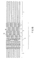
- FIGS. 1A and 1B show plan views of magnetic recording media (discrete track media) that are supposed to be manufactured using the imprint lithography method.
- these magnetic recording media include a servo region 1 in which marks of a magnetic film are formed and a data region 2 in which discrete tracks of the magnetic film are formed.
- the servo region 1 includes a preamble region 11, an address region 12 and a burst region (a positioning burst region) 13.
- the burst region 13 may include rectangular magnetic marks or may include rectangular hole marks formed in a magnetic film.
- the signal pattern of the burst region either in the media of FIG. 1A or in the media of FIG. 1B has a same function for a magnetic recording apparatus.
- the burst pattern shown in FIG. 1A is referred to as a "mark-type", and the burst pattern shown in FIG. 1B is referred to as a "hole-type" herein.
- recesses between the magnetic marks may be filled with a non-magnetic film or may be left unfilled. The following will be described for the embodiments that the recesses between the magnetic marks are filled with a non-magnetic film.
- the magnetic marks are magnetized in the perpendicular direction in advance.
- the preamble region 11 is read out by the magnetic head 50 prior to the address region 12 and the burst region 13, and the data read out from this region are used to adjust the amplification factor of the signal amplifier to maintain a given amplitude.
- the preamble region 11 has such a pattern that a plurality of linear marks of the magnetic film extend in the track width direction (that is, the radial direction of the disk). This pattern makes it possible to generate similar signals regardless of the positions of the magnetic head 50.
- the address region 12 has track data and sector data.
- the track data are written in gray code so that they can be read with the magnetic head 50 in seeking.
- the burst region 13 is provided for positioning the magnetic head 50 to the center of a predetermined track.
- the burst region 13 includes signal sections 13a and non-signal sections 13b.
- Each signal section 13a in FIG. 1A includes rectangular marks of the magnetic film and spaces filled with the non-magnetic film between the marks which are formed with the same intervals in the track direction, i.e., the circumferential direction of the disk.
- Each non-signal section 13b in FIG. 1A has no magnetic mark and includes the non-magnetic film alone.
- Each signal section 13a in FIG. 1B also includes rectangular marks and spaces similar to those in FIG. 1A.
- each non-signal section 13b in FIG. 1B includes the magnetic film alone.
- the signal section 13a includes burst A to burst D that are located at positions relatively different from each other with respect to the center of the track.
- the intensity of the readout signals varies in accordance with the displacement of the magnetic head 50 from the center of the track. More specifically, when the center of the magnetic head 50 coincides with the center of the track, the intensities of the signals obtained from the burst A and burst B are equal to each other.
- the position of the head with respect to the center of the track can be calculated based on the readout signals from the burst region, and the magnetic head 50 can be positioned to the center of the track by feedback control.
- the burst region 13 in FIG. 1A includes the signal section 13a, in which rectangular magnetic marks and spaces filled with the non-magnetic film between the marks are formed with the same intervals in the track direction, and the non-signal section having no magnetic mark and including the non-magnetic film alone.
- the area ratio of the magnetic marks in the burst region 13 is about 25%.
- the burst region 13 in FIG. 1B includes the signal section 13a similar to that in FIG. 1A and the non-signal section including the magnetic film alone. With this arrangement, the area ratio of the magnetic marks in the burst region 13 is about 75%.
- the area ratio of the magnetic discrete track in the data region 2 is set to about 67%.
- the area ratios of the magnetic marks in respective regions of the magnetic recording media shown in FIG. 1A (or FIG. 1B) are: about 50% for the preamble region 11, about 25% for the mark-type burst region 13 (or about 75% for the hole-type burst region 13), and about 67% for the data region.
- an imprint stamper having recesses corresponding to the magnetic marks and projections corresponding to the non-magnetic spaces is used.
- the imprint stamper used for the manufacture of the above magnetic recording media has area ratios of the projections substantially reverse to those of the magnetic marks in the media, that is, about 50% for the preamble portion, about 75% (or about 25%) for the burst portion, and about 33% for the data region.
- the imprint stamper is manufactured by, for example, processes including the electron beam lithography as described above, and therefore the height of the projections is at constant in any region.
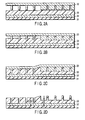
- FIGS. 2A to 2D a problem which may possibly arise when the magnetic recording media having the structure shown in FIG. 1 is manufactured using the imprint stamper, will be described.
- two adjacent regions of the imprint stamper 20, having area ratios of the projections significantly different from each other, are shown in FIGS. 2A to 2D.
- FIG. 2A shows a state in which the resist 33 is applied to the magnetic film 32 formed on the substrate 31, and the imprint stamper 20 is placed to face the resist 33.
- the area ratio of the projections is relatively lower in the region on the left, whereas the area ratio of the projections is relatively higher in the region on the right.
- FIG. 2B shows an initial stage of the imprint process in which the imprint stamper 20 is pressed against the resist 33 by applying a pressure.
- the projections of the imprint stamper 20 are pushed into the resist 33, and a part of the resist which is pushed aside by the projections enters the recesses of the imprint stamper 20.
- the recesses of the imprint stamper 20 are filled with a part of the resist pushed aside by the projections at this stage.
- the resist has high viscosity and therefore it cannot move for a long distance during the imprinting process.
- FIG. 2C shows a final stage of the imprint process.
- the state of the right region is not different from that of FIG. 2B.
- the projections are pushed further into the resist from the state shown in FIG. 2B, increasing the imprint depth.
- distortion is produced in the intermediate region between the right and the left regions of the imprint stamper 20.
- the recesses of the imprint stamper 20 are completely filled with a part of the resist pushed aside. Therefore, if a further pressure is applied to the imprint stamper 20, the projections can no longer be pushed into the resist in any of the regions. Thus, at the point where the imprint depth can no longer be increased, the imprint process is finished.
- FIG. 2D shows a state of the resist after the imprint stamper 20 has been removed. Because imprint depths have been different in the right and the left regions of the imprint stamper 20 as described above, it is natural that the thicknesses of the resist residue remaining on the magnetic film 32 are different between the right region and the left region.
- the thicknesses of the magnetic film 32 thus processed become uneven due to the difference in the thicknesses of the resist residue. More specifically, in the left region shown in FIG. 2D, the thickness t1 of the resist residue is small, and therefore the etching depth of the magnetic film 32 becomes relatively deep. By contrast, in the right region shown in FIG. 2D, the thickness t2 of the resist residue is large, and therefore the etching depth of the magnetic film 32 becomes relatively shallow.
- the design of the imprint stamper 20 used in the case where a magnetic recording media having the mark-type burst structure shown in FIG. 1A is manufactured using the imprint lithography method as described above will be specifically described.
- the imprint stamper 20 to be used in this case has the following area ratios of the projections: that is, about 50% for the preamble portion 20a, about 75% for the burst portion 20b, and about 33% for the data portion 20c, as indicated in FIG. 3A.
- the pattern of the projections is not illustrated in the imprint stamper 20 shown in the figure.
- the imprint depth in the address region becomes a level close to the imprint depth in the preamble region or the burst region. Therefore, the address region is not illustrated in this figure.
- FIG. 3B shows the imprint depths to the resist 33 by the projections of the imprint stamper 20 in the preamble portion 20a, burst portion 20b and data portion 20c.
- the imprint depth is largest in the data portion 20c, it is smallest in the burst portion 20b, and it is at an intermediate level between them in the preamble portion 20b.
- the thickness of the resist residue is smallest in the data region, it is largest in the burst region, and it is at an intermediate level between them in the preamble portion.
- the etching depth in the magnetic film 32 is largest in the data region, it is smallest in the burst region, and it is at an intermediate level between them in the preamble portion. Therefore, after the etching, the thickness of the magnetic film 32 is smallest in the data region, it is largest in the burst region, and it is at an intermediate level between them in the preamble portion.
- the signal intensity and recording characteristics vary in accordance with the thickness of the magnetic film 32. Thus, it is difficult to perform stable read and write. The same problem also arises in the magnetic recording media having the hole-type burst structure.
- marks of the magnetic film are formed in the non-signal section of the burst region.
- the difference in the area ratios of the magnetic marks is preferably made as small as possible between the servo region (including the preamble region and burst region) and the data region.
- the area ratio of the magnetic marks in the burst region should be set to an intermediate level between that in the preamble region and that in the data region.
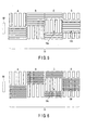
- FIG. 4 is a plan view of the magnetic recording media according to this embodiment.
- the magnetic recording media includes the servo region 1 in which marks of a magnetic film are formed, and the data region 2 in which discrete tracks of the magnetic film are formed.
- the servo region 1 includes the preamble region 11, the address region 12 and the burst region 13.
- the area ratio of the magnetic marks in the preamble region 11 is about 50%.
- the pattern of the magnetic marks varies depending on the value of the address. Accordingly, the area ratio of the magnetic marks varies depending on the address.
- the area ratio of the magnetic discrete track in the data region 2 is set to about 67%.
- the burst region 13 shown in FIG. 4 includes a signal section 13a and a non-signal section 13c, and the lengths of the signal section 13a and non-signal section 13c are the same in the track direction.
- each signal section 13a four rectangular marks (four first marks) of the magnetic film and spaces filled with the non-magnetic film between the marks are formed with the same intervals in the track direction.
- the signal section 13a includes burst A to burst D that are located at positions relative different from each other with respect to the center of the track.
- the signal section 13a has the same structure as the signal section shown in FIG. 1.
- the non-signal section 13c eleven rectangular marks (eleven second marks) of the magnetic film, in-plane geometry of which is a rectangle, and spaces filled with the non-magnetic film between the marks are formed periodically with the same intervals in the track direction.
- the pitch of the rectangular magnetic marks in the non-signal section 13c is different from the pitch of the rectangular magnetic marks in the signal section 13a.
- the rectangular magnetic marks and the non-magnetic spaces between them are formed with the same intervals in the track direction, respectively. Therefore, with this arrangement, the area ratio of the magnetic marks is about 50% in the burst region.
- the area ratios of the magnetic marks are: about 50% for the preamble region 11, about 50% for the burst region 13, and about 67% for the data region 2.
- the difference in the area ratios is relatively small.
- the area ratios of the projections are: about 50% for the preamble portion, about 50% for the burst portion, and about 33% for the data portion. Since the difference in the area ratios of the projections between respective portions is relatively small in this imprint stamper, it is possible to reduce the difference in thicknesses of the resist residue after imprinting. Therefore, magnetic marks almost uniform in thickness can be formed by etching the magnetic film using this resist as a mask. Since the burst region in this embodiment includes periodically formed magnetic marks either in the signal section 13a or in the non-signal section 13b, there is no distinction between the mark-type and the hole-type.
- burst signals obtained from the magnetic recording media shown in FIG. 4 will be described.
- four rectangular magnetic marks are arranged in the signal section 13a of the burst region 13 and eleven rectangular magnetic marks are arranged in the non-signal section 13c, and thus the pitches of the rectangular marks in these two regions are different from each other.
- the frequency of signals obtained from the signal section 13a is 4x (where x is a constant) Hz
- the frequency of signals obtained from the non-signal section 13c is 11x Hz. Therefore, only the signals having a frequency component from the signal section 13a can be detected by cutting off the signals having a frequency component from the non-signal section 13c.
- the magnetic recording media according to the embodiment of the present invention comprises magnetic marks almost uniform in thickness as described above, stable read and write can be realized.
- FIG. 5 is a plan view of a burst region of the magnetic recording media in this embodiment.
- the non-signal section 13c in the burst region 13 shown in FIG. 5 includes a plurality of linear marks of the magnetic film, in-plane geometry of which is a stripe parallel to the track direction. The rest of the structure is similar to that shown in FIG. 4.
- the pitch in the track width direction of the linear marks (second marks) formed in the non-signal section 13c shown in FIG. 5 is not particularly limited.
- the width of each linear magnetic mark and the width of each non-magnetic space between the linear marks are set to a ratio of 3 to 1.
- the area ratio of the magnetic marks in the non-signal section 13c is about 75%. Consequently, the area ratio of the magnetic marks in the burst region 13 becomes about 63%.
- the area ratios of the magnetic marks are: about 50% for the preamble region 11, about 63% for the burst region 13, and about 67% for the data region 2.
- the difference in the area ratios is relatively small. Consequently, this embodiment also produces advantages similar to those in the first embodiment.
- FIG. 6 is a plan view of a burst region of the magnetic recording media in this embodiment.
- the non-signal section 13c in the burst region 13 shown in FIG. 6 includes a plurality of dot marks of the magnetic film, in-plane geometry of which is a dot, formed in a periodic pattern.
- the pitch of the dot magnetic marks (second marks) in the non-signal section 13c is different from the pitch of the rectangular magnetic marks (first marks) in the signal section 13a.
- the rest of the structure is similar to that shown in FIG. 4. It should be noted that the pitch in the track width direction of the dot marks formed in the non-signal section 13c shown in FIG. 6 is not particularly limited.
- the width of each dot magnetic mark and the width of each non-magnetic space between the dot marks are set to a ratio of 3 to 1 in the track direction and a ratio of 3 to 1 in the track width direction.
- the area ratio of the magnetic marks in the non-signal section 13c is about 56%. Consequently, the area ratio of the magnetic marks in the burst region 13 becomes about 54%.
- the area ratios of the magnetic marks are: about 50% for the preamble region 11, about 54% for the burst region 13, and about 67% for the data region 2.
- the difference in the area ratios is relatively small.
- the pitch of the dot magnetic marks in the non-signal section 13c is different from the pitch of the rectangular magnetic marks in the signal section 13a. Therefore, only the signals having a frequency component from the signal section 13a can be detected by cutting off the signals having a frequency component from the non-signal section 13c. Consequently, this embodiment also produces advantages similar to those in the first embodiment.
- the area ratio of the magnetic marks in the entire burst region 13 can be adjusted by appropriately setting the width of each magnetic mark and the width of each non-magnetic space between the marks in the non-signal section 13c of the burst region 13.
- the structure of the non-signal section 13c in the burst region 13 is not limited to those shown in FIGS. 4 to 6.
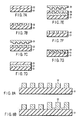
- FIGS. 7A to 7G Next, a method of manufacturing a magnetic recording media according to an embodiment of the present invention will be described with reference to FIGS. 7A to 7G.
- an imprint stamper is manufactured as described below.
- the electron beam resist 22 is applied to the master plate 21. It is preferable that the master plate 21 be made of silicon or glass.
- the electron beam resist 22 is subjected to electron beam direct write, and then is developed to form a pattern of projections and recesses therein.
- the master plate 21 having the electron beam resist 22 on which the pattern of the projections and recesses is formed is subjected to electroforming, and then the metal disk formed by electroforming is peeled off.
- the imprint stamper 20 is manufactured.
- the material for the stamper Ni is preferable, although it is not particularly limited.
- Projections having a reverse pattern to the pattern of the magnetic marks in the magnetic recording media shown in FIG. 4, for example, are formed in the surface of the imprint stamper 20.
- the area ratios of the projections on the imprint stamper 20 are: about 50% for the preamble portion, about 50% for the burst portion, and about 33% for the data portion.
- the imprint stamper can be manufactured by etching the master plate 21 after the step shown in FIG. 7B using the resist pattern as a mask, thereby transferring the pattern of the projections and recesses in the resist to the master plate 21.
- a magnetic recording media is manufactured by using the imprint lithography method as described below.
- the magnetic film 32 suitable for perpendicular recording is formed on the substrate 31.
- a soft magnetic underlayer and a ferromagnetic recording layer be formed as the magnetic film 32 to form a perpendicular two-layered media.
- the resist 33 for imprinting is applied to the magnetic film 32.
- the stamper 20 is placed to face the resist 33 on the substrate 31, and the stamper 20 is pressed against the resist 33 by applying a pressure to transfer the pattern of the projections on the surface of the stamper 20 onto the surface of the resist 33. After that, the stamper 20 is removed. As shown in FIG.
- etching of the magnetic film 32 is performed to process the magnetic film 32 using the resist 33, on which the pattern of the projections and recesses is formed, as a mask. As a result, a pattern of the magnetic marks as shown in FIG. 4 is formed.
- the area ratios of the magnetic marks are: about 50% for the preamble region, about 50% for the burst region, and about 67% for the data region.
- the carbon protective film 34 is formed on the magnetic film 32, and further a lubricant is applied thereon, and thus the magnetic recording media is manufactured.
- the imprint stamper 20 in which the difference in the area ratios of the projections between the respective portions is small, the difference in the thicknesses of the resist residue after imprinting can be reduced to a low level. Therefore, using such a resist as a mask in the etching of the magnetic film, magnetic marks almost uniform in thickness can be formed.
- FIG. 8A shows a cross-sectional view of the magnetic film having a pattern of the magnetic marks shown in FIG. 4, and FIG. 8B shows a cross-sectional view of the magnetic film having a pattern of the magnetic marks shown in FIG. 1A.
- the thicknesses of the magnetic marks 32 after processing are substantially uniform. This is because the difference in the area ratios of the projections between the respective portions in the imprint stamper is small and the thicknesses of the resist residue after imprinting is substantially uniform in any portion on the media.
- the thicknesses of the magnetic marks 32 after processing are uneven.
- the substrate-patterned discrete track media also provides the same effect as that of the magnetic film-patterned discrete track media that has been described with referring to FIGS. 7A to 7G.
- a magnetic film on a projection and a magnetic film in a recess correspond to a magnetic mark and a non-magnetic film, respectively.
- a method of manufacturing a substrate-patterned discrete track media will be described with reference to FIGS. 9A to 9G.
- FIGS. 9A to 9C Processed for manufacturing an imprint stamper shown in FIGS. 9A to 9C are similar to those in FIGS. 7A to 7C.
- a substrate having projections and recesses processed on the surface thereof is manufactured by using the imprint lithography method as described below.
- the resist 42 for imprinting is applied to the substrate 41.
- the stamper 20 is placed to face the resist 42 on the substrate 41, and the stamper 20 is pressed against the resist 42 by applying a pressure to transfer the pattern of the projections on the surface of the stamper 20 onto the surface of the resist 42. After that, the stamper 20 is removed.
- etching of the substrate 41 is performed using the resist 42, on which the pattern of the projections and recesses is formed, as a mask.
- the magnetic film 43 suitable for perpendicular recording on the projections and in the recesses of the substrate 41.
- a soft magnetic underlayer and a ferromagnetic recording layer be formed as the magnetic film 43 to form a perpendicular two-layered media.
- the carbon protective film 44 is formed on the magnetic film 43, and further a lubricant is applied thereon, and thus the magnetic recording media is manufactured.
- the imprint stamper 20 in which the difference in the area ratios of the projections between the respective portions is small, the difference in the thicknesses of the resist residue after imprinting can be reduced to a low level. Therefore, using such a resist as a mask in the etching of the substrate, projections almost uniform in height can be formed.
- FIG. 10A shows a cross-sectional view of the substrate-patterned discrete track media corresponding to FIG. 4, and FIG. 10B shows a cross-sectional view of the substrate-patterned discrete track media corresponding to FIG. 1A.
- the heights of the projections of substrate 41 after processing are substantially uniform. This is because the difference in the area ratios of the projections between the respective portions in the imprint stamper is small and the thicknesses of the resist residue after imprinting is substantially uniform in any portion on the substrate.
- FIG. 10B (a comparative example) the heights of the projections of the substrate 41 after processing are uneven.
- the magnetic recording apparatus 150 is of a type that uses a rotary actuator.
- the magnetic disk 30 having such a pattern of magnetic marks as shown in any one of FIGS. 4 to 6, is mounted to the spindle 152, and it is rotated in the direction indicated by arrow A by a motor (not shown) which operates in reply to control signals output from a driver controller (not shown).
- the magnetic recording apparatus 150 may have a plurality of magnetic disks 30.
- the head slider 153 used to write to and read from data stored in the magnetic disk 30 is mounted on a tip end of the suspension 154.
- the suspension 154 is connected to an end of the actuator arm 155.
- the voice coil motor 156 a type of a linear motor, is provided at the other end of the actuator arm 155.
- the voice coil motor 156 comprises a driving coil (not shown) wound around a bobbin portion and a magnetic circuit made of a permanent magnet and a counter-yoke arranged with sandwiching the coil therebetween.
- the actuator arm 155 is supported by ball bearings (not shown) provided at upper and lower portions of the pivot 157, and thus the arm 155 is set rotatable by the voice coil motor 156.
- the surface (ABS) of the head slider 153 that faces the media is held to have a certain flying height from the surface of the magnetic disk 30.
- the slider may be of a so-called “in-contact type", which is brought into contact with the magnetic disk 30.
- the magnetic recording apparatus can perform stable read and write.
Landscapes
- Magnetic Record Carriers (AREA)
- Manufacturing Of Magnetic Record Carriers (AREA)
- Recording Or Reproducing By Magnetic Means (AREA)
- Moving Of The Head To Find And Align With The Track (AREA)
Abstract
Description
Claims (19)
- A magnetic recording media comprising: a servo region (1) including a preamble region (11) and a burst region (13), and having marks of a magnetic film; and a data region (2) having discrete tracks of the magnetic film, characterized in that the burst region (13) including a signal section (13a) and a non-signal section (13c), the signal section (13a) including first marks of the magnetic film formed in a periodic pattern in a track direction, and the non-signal section (13c) including second marks of the magnetic film having a pattern different from the pattern of the first marks in the signal section (13a).
- The magnetic recording media according to claim 1, characterized in that the first marks of the magnetic film included in the signal section (13a) are rectangular marks, in-plane geometry of which is a rectangle, formed in a periodic pattern in a track direction.
- The magnetic recording media according to claim 2, characterized in that the non-signal section (13c) includes the second marks of the magnetic film, in-plane geometry of which is a rectangle, formed in a periodic pattern in a track direction, and in that a pitch of the second marks of the magnetic film in the non-signal section (13c) is different from a pitch of the first marks of the magnetic film in the signal section (13a).
- The magnetic recording media according to claim 2, characterized in that the non-signal section (13c) includes second marks of the magnetic film, in-plane geometry of which is a stripe parallel with the track direction.
- The magnetic recording media according to claim 2, characterized in that the non-signal section (13c) includes the second marks of the magnetic film, in-plane geometry of which is a dot, formed in a periodic pattern, and in that a pitch of the second marks of the magnetic film in the non-signal section (13c) is different from a pitch of the first marks of the magnetic film in the signal section (13a).
- The magnetic recording media according to claim 1, characterized in that an area ratio of magnetic marks in the burst region (13) is set at an intermediate value between an area ratio of the magnetic marks in the preamble region (11) and the area ratio of the discrete tracks in the data region (2).
- The magnetic recording media according to claim 1, characterized in that the media comprises an address region (12) between the preamble region (11) and the burst region (13).
- A method of manufacturing a magnetic recording media, characterized by comprising:depositing a magnetic film (32) on a substrate (31), and applying a resist (33) to the magnetic film (32);pressing an imprint stamper (20) on the resist (33) to imprint a pattern of projections and recesses corresponding to a pattern of the marks in the servo region (1) and the data region (2) of the magnetic recording media according to claim 1; andprocessing the magnetic film (32) using the imprinted resist (33) as a mask.
- The method according to claim 8, characterized in that the imprint stamper (20) is formed by electroforming.
- A method of manufacturing a magnetic recording media, characterized by comprising:applying a resist (42) to a substrate (41);pressing an imprint stamper (20) on the resist (42) to imprint a pattern of projections and recesses corresponding to a pattern of the marks in the servo region (1) and the data region (2) of the magnetic recording media according to claim 1; andprocessing the substrate (41) using the imprinted resist (42) as a mask, followed by depositing a magnetic film (43).
- The method according to claim 10, wherein the imprint stamper (20) is formed by electroforming.
- A magnetic recording apparatus comprising:a magnetic recording media (30); and a magnetic head (153) configured to write to and read from the magnetic recording media (30), the magnetic recording media (30) comprising a servo region (1) including a preamble region (11) and a burst region (13), and having marks of a magnetic film and a data region (1) having discrete tracks of the magnetic film, characterized in that the burst region (13) including a signal section (13a) and a non-signal section (13c), the signal section (13a) including first marks of the magnetic film formed in a periodic pattern in a track direction, and the non-signal section (13c) including second marks of the magnetic film having a pattern different from the pattern of the first marks in the signal section (13a).
- The magnetic recording apparatus according to claim 12, characterized in that the first marks of the magnetic film included in the signal section (13a) are rectangular marks, in-plane geometry of which is a rectangle, formed in a periodic pattern in a track direction.
- The magnetic recording apparatus according to claim 13, characterized in that the non-signal section (13c) includes the second marks of the magnetic film, in-plane geometry of which is a rectangle, formed in a periodic pattern in a track direction, and in that a pitch of the second marks of the magnetic film in the non-signal section (13c) is different from a pitch of the first marks of the magnetic film in the signal section (13a).
- The magnetic recording apparatus according to claim 13, characterized in that the non-signal section (13c) includes the second marks of the magnetic film, in-plane geometry of which is a stripe parallel with the track direction.
- The magnetic recording apparatus according to claim 13, characterized in that the non-signal section (13c) includes the second marks of the magnetic film, in-plane geometry of which is a dot, formed in a periodic pattern, and in that a pitch of the second marks of the magnetic film in the non-signal section (13c) is different from a pitch of the first marks of the magnetic film in the signal section (13a).
- The magnetic recording apparatus according to claim 12, characterized in that an area ratio of magnetic marks in the burst region (13) is set at an intermediate value between an area ratio of the magnetic marks in the preamble region (11) and the area ratio of the discrete tracks in the data region (2).
- The magnetic recording apparatus according to claim 12, characterized in that the media comprises an address region (12) between the preamble region (11) and the burst region (13).
- The magnetic recording apparatus according to claim 12, characterized in that signals from the marks in the non-signal section (13c) is cut-off from signals from the marks in the signal section (13a) based on frequency.
Applications Claiming Priority (2)
| Application Number | Priority Date | Filing Date | Title |
|---|---|---|---|
| JP2004108107A JP4074262B2 (en) | 2004-03-31 | 2004-03-31 | Magnetic recording medium, manufacturing method thereof, and magnetic recording / reproducing apparatus |
| JP2004108107 | 2004-03-31 |
Publications (2)
| Publication Number | Publication Date |
|---|---|
| EP1596398A2 true EP1596398A2 (en) | 2005-11-16 |
| EP1596398A3 EP1596398A3 (en) | 2006-11-22 |
Family
ID=34940619
Family Applications (1)
| Application Number | Title | Priority Date | Filing Date |
|---|---|---|---|
| EP05251760A Withdrawn EP1596398A3 (en) | 2004-03-31 | 2005-03-22 | Magnetic recording media, method of manufacturing the same and magnetic recording apparatus |
Country Status (4)
| Country | Link |
|---|---|
| US (1) | US7388725B2 (en) |
| EP (1) | EP1596398A3 (en) |
| JP (1) | JP4074262B2 (en) |
| CN (1) | CN100377210C (en) |
Cited By (2)
| Publication number | Priority date | Publication date | Assignee | Title |
|---|---|---|---|---|
| EP1909279A1 (en) * | 2006-09-26 | 2008-04-09 | Fujitsu Limited | Clock extraction method for patterned medium and circuit thereof |
| EP2012308A1 (en) * | 2007-07-04 | 2009-01-07 | Samsung Electronics Co., Ltd. | Magnetic recording medium, hard disk drive employing the same, and method of measuring write read offset of the hard disk drive |
Families Citing this family (39)
| Publication number | Priority date | Publication date | Assignee | Title |
|---|---|---|---|---|
| JP4358067B2 (en) * | 2004-08-06 | 2009-11-04 | 株式会社東芝 | Magnetic recording medium and magnetic recording apparatus |
| JP4077437B2 (en) * | 2004-09-16 | 2008-04-16 | Tdk株式会社 | Information recording medium and recording / reproducing apparatus |
| JP2006216171A (en) * | 2005-02-04 | 2006-08-17 | Tdk Corp | Magnetic recording medium, recording or reproducing apparatus, and stamper |
| CN100416653C (en) * | 2005-02-16 | 2008-09-03 | Tdk股份有限公司 | Magnetic recording medium, recording and reproducing device, and stamper |
| CN100429697C (en) * | 2005-02-16 | 2008-10-29 | Tdk股份有限公司 | Magnetic recording medium, recording/reproducing apparatus, and stamper |
| JP2006228347A (en) * | 2005-02-18 | 2006-08-31 | Sony Corp | Magnetic disk manufacturing method |
| JP4218896B2 (en) | 2005-03-02 | 2009-02-04 | Tdk株式会社 | Magnetic recording medium, recording / reproducing apparatus, and stamper |
| JP2006260713A (en) | 2005-03-18 | 2006-09-28 | Toshiba Corp | Recording medium, recording / reproducing apparatus, and recording / reproducing method |
| JP4649262B2 (en) * | 2005-04-19 | 2011-03-09 | 株式会社東芝 | Method for manufacturing magnetic recording medium |
| JP4542953B2 (en) | 2005-06-10 | 2010-09-15 | 株式会社東芝 | Magnetic disk medium and magnetic recording / reproducing apparatus |
| JP4581963B2 (en) * | 2005-10-27 | 2010-11-17 | Tdk株式会社 | Stamper, uneven pattern forming method, and information recording medium manufacturing method |
| JP4675758B2 (en) | 2005-11-16 | 2011-04-27 | 昭和電工株式会社 | Magnetic recording medium |
| JP2007164958A (en) * | 2005-11-21 | 2007-06-28 | Tdk Corp | Recording/reproducing apparatus and method of measuring parameter |
| KR100738101B1 (en) * | 2006-01-26 | 2007-07-12 | 삼성전자주식회사 | Patterned Media and Manufacturing Method Thereof |
| JP4533854B2 (en) | 2006-03-06 | 2010-09-01 | 株式会社東芝 | Magnetic recording / reproducing apparatus, magnetic recording method, and magnetic recording / reproducing method |
| JP4585476B2 (en) * | 2006-03-16 | 2010-11-24 | 株式会社東芝 | Patterned medium and magnetic recording apparatus |
| JP2007287300A (en) | 2006-03-24 | 2007-11-01 | Fujitsu Ltd | Magnetic recording medium manufacturing method and magnetic recording medium |
| JP4551880B2 (en) * | 2006-03-30 | 2010-09-29 | 株式会社東芝 | Method for manufacturing magnetic recording medium |
| JP4675812B2 (en) * | 2006-03-30 | 2011-04-27 | 株式会社東芝 | Magnetic recording medium, magnetic recording apparatus, and method of manufacturing magnetic recording medium |
| JP2007273042A (en) * | 2006-03-31 | 2007-10-18 | Toshiba Corp | Magnetic recording medium and magnetic recording / reproducing apparatus |
| JP4543004B2 (en) * | 2006-05-11 | 2010-09-15 | 株式会社東芝 | Pattern forming method, imprint mold, and magnetic recording medium manufacturing method |
| JP4728892B2 (en) | 2006-06-30 | 2011-07-20 | 株式会社東芝 | Magnetic recording medium and method for manufacturing the same |
| JP2008016084A (en) * | 2006-07-03 | 2008-01-24 | Toshiba Corp | Method for manufacturing magnetic recording medium |
| WO2008053547A1 (en) * | 2006-11-01 | 2008-05-08 | Fujitsu Limited | Pattern transferring stamper, method for manufacturing magnetic recording medium using the pattern transferring stamper, and the magnetic recording medium |
| US20080190483A1 (en) * | 2007-02-13 | 2008-08-14 | Carpenter R Douglas | Composition and method of preparing nanoscale thin film photovoltaic materials |
| JP2008226395A (en) * | 2007-03-15 | 2008-09-25 | Fujitsu Ltd | Magnetic disk, stamper used for manufacturing the magnetic disk, and method for manufacturing the magnetic disk |
| JP2008243266A (en) * | 2007-03-26 | 2008-10-09 | Hitachi Global Storage Technologies Netherlands Bv | Magnetic recording medium, servo recording method on magnetic recording medium, and magnetic recording apparatus |
| JP2008282512A (en) * | 2007-05-14 | 2008-11-20 | Toshiba Corp | Magnetic recording medium and magnetic recording / reproducing apparatus |
| JP2009006619A (en) * | 2007-06-29 | 2009-01-15 | Hitachi Ltd | Nanoimprint mold and recording medium |
| JP2007287322A (en) * | 2007-07-09 | 2007-11-01 | Tdk Corp | Information recording medium and recording/reproducing device |
| KR100924698B1 (en) * | 2007-07-24 | 2009-11-03 | 삼성전자주식회사 | Magnetic recording device |
| JP4908339B2 (en) * | 2007-07-30 | 2012-04-04 | 株式会社東芝 | Disk storage device and disk medium |
| JP5004225B2 (en) | 2007-09-19 | 2012-08-22 | 独立行政法人産業技術総合研究所 | Mold manufacturing method for imprint lithography |
| JP4382843B2 (en) * | 2007-09-26 | 2009-12-16 | 株式会社東芝 | Magnetic recording medium and method for manufacturing the same |
| KR20090059848A (en) * | 2007-12-07 | 2009-06-11 | 삼성전자주식회사 | Method for recording track information on a pattern magnetic recording medium and a pattern magnetic recording medium |
| JP2010009729A (en) * | 2008-06-30 | 2010-01-14 | Toshiba Corp | Imprint stamper, method of manufacturing imprint stamper, magnetic recording medium, method of manufacturing magnetic recording medium and magnetic disk apparatus |
| JP2008310957A (en) * | 2008-09-29 | 2008-12-25 | Tdk Corp | Magnetic recording medium, recording and reproducing device, and stamper |
| JP5050105B2 (en) * | 2011-01-12 | 2012-10-17 | 株式会社東芝 | Magnetic recording device |
| US20220253619A1 (en) * | 2021-02-08 | 2022-08-11 | Mark Eklund | Micro-track device (M-TDnm) |
Family Cites Families (10)
| Publication number | Priority date | Publication date | Assignee | Title |
|---|---|---|---|---|
| JPS62256225A (en) * | 1986-04-30 | 1987-11-07 | Hitachi Ltd | magnetic disk |
| JPH02301018A (en) * | 1989-05-16 | 1990-12-13 | Sony Corp | Magnetic recording medium |
| JP2946636B2 (en) * | 1990-05-21 | 1999-09-06 | ソニー株式会社 | Track address pattern of magnetic disk drive |
| JPH0765363A (en) * | 1993-08-26 | 1995-03-10 | Hitachi Ltd | Magnetic recording medium, magnetic recording apparatus, and manufacturing method thereof |
| JP2000067538A (en) * | 1998-08-24 | 2000-03-03 | Alps Electric Co Ltd | Disk on which servo pattern is recorded and method of processing servo pattern read from disk |
| JP4185230B2 (en) * | 1999-02-19 | 2008-11-26 | Tdk株式会社 | Magnetic recording medium |
| US6643082B1 (en) * | 1999-06-08 | 2003-11-04 | Seagate Technology Llc | Servo sector format for a patterned media |
| JP3757098B2 (en) * | 2000-06-01 | 2006-03-22 | 富士通株式会社 | Disk device and disk medium |
| AU2001290870A1 (en) * | 2000-09-12 | 2002-03-26 | Seagate Technology Llc | Method and apparatus for minimizing slider fly heights over patterned media |
| JP4209231B2 (en) * | 2003-03-26 | 2009-01-14 | Tdk株式会社 | Magnetic recording medium and method for manufacturing magnetic recording medium |
-
2004
- 2004-03-31 JP JP2004108107A patent/JP4074262B2/en not_active Expired - Fee Related
-
2005
- 2005-03-22 EP EP05251760A patent/EP1596398A3/en not_active Withdrawn
- 2005-03-24 US US11/087,595 patent/US7388725B2/en not_active Expired - Fee Related
- 2005-03-31 CN CNB2005100600872A patent/CN100377210C/en not_active Expired - Fee Related
Cited By (2)
| Publication number | Priority date | Publication date | Assignee | Title |
|---|---|---|---|---|
| EP1909279A1 (en) * | 2006-09-26 | 2008-04-09 | Fujitsu Limited | Clock extraction method for patterned medium and circuit thereof |
| EP2012308A1 (en) * | 2007-07-04 | 2009-01-07 | Samsung Electronics Co., Ltd. | Magnetic recording medium, hard disk drive employing the same, and method of measuring write read offset of the hard disk drive |
Also Published As
| Publication number | Publication date |
|---|---|
| CN100377210C (en) | 2008-03-26 |
| CN1677494A (en) | 2005-10-05 |
| JP2005293730A (en) | 2005-10-20 |
| JP4074262B2 (en) | 2008-04-09 |
| US7388725B2 (en) | 2008-06-17 |
| EP1596398A3 (en) | 2006-11-22 |
| US20050219730A1 (en) | 2005-10-06 |
Similar Documents
| Publication | Publication Date | Title |
|---|---|---|
| US7388725B2 (en) | Magnetic recording media, method of manufacturing the same and magnetic recording apparatus | |
| US6139936A (en) | Discrete track media produced by underlayer laser ablation | |
| US8289645B2 (en) | Magnetic disk apparatus | |
| US8003236B2 (en) | Method for making a master mold with high bit-aspect-ratio for nanoimprinting patterned magnetic recording disks, master mold made by the method, and disk imprinted by the master mold | |
| US7149042B2 (en) | Master carrier for magnetic transfer | |
| JP2006277869A (en) | Magnetic recording medium, reticle for electron beam reduced projection drawing, and method for manufacturing magnetic recording medium | |
| US6898031B1 (en) | Method for replicating magnetic patterns on hard disk media | |
| US6980380B2 (en) | Master information carrier and method for manufacturing magnetic disk | |
| US7505220B2 (en) | Magnetic recording medium, recording/reproducing apparatus, and stamper | |
| US7105280B1 (en) | Utilizing permanent master for making stampers/imprinters for patterning of recording media | |
| US20060269791A1 (en) | Magnetic recording medium, magnetic recording and reproducing apparatus, stamper, method of manufacturing stamper, and method of manufacturing magnetic recording medium | |
| JP2006099932A (en) | Magnetic recording medium, magnetic recording/reproducing apparatus, and stamper for manufacturing magnetic recording medium | |
| US7754354B2 (en) | Patterned medium and method of manufacturing the same | |
| US20090244785A1 (en) | Magnetic recording medium, magnetic recording/reproduction device, and method of manufacturing magnetic recording medium | |
| CN100433135C (en) | Magnetic recording medium, substrate for magnetic recording medium, and magnetic recording device | |
| JP4110204B2 (en) | Magnetic recording medium, manufacturing method thereof, and magnetic recording / reproducing apparatus | |
| US7362524B2 (en) | Magnetic pattern transfer method | |
| EP1511013B1 (en) | Process for producing master carrier for magnetic transfer | |
| US7522362B2 (en) | Amplitude servo pattern, magnetic recording medium and the manufacturing method, patterned magnetic transfer master substrate used in the manufacturing method, and magnetic recording/reproducing apparatus | |
| US7170699B2 (en) | Master disk having grooves of different depths for magnetic printing and manufacturing method therefor | |
| JP2003141715A (en) | Master carrier for magnetic transfer | |
| JP2007273042A (en) | Magnetic recording medium and magnetic recording / reproducing apparatus | |
| US20110181975A1 (en) | Method of manufacturing a master disk for magnetic transfer | |
| US8031562B2 (en) | Master disk for magnetic transfer, a method of drawing a magnetic transfer pattern, and a magnetic recording medium having a transferred magnetic transfer pattern | |
| JP4035043B2 (en) | Master information carrier and magnetic disk manufacturing method |
Legal Events
| Date | Code | Title | Description |
|---|---|---|---|
| PUAI | Public reference made under article 153(3) epc to a published international application that has entered the european phase |
Free format text: ORIGINAL CODE: 0009012 |
|
| 17P | Request for examination filed |
Effective date: 20050408 |
|
| AK | Designated contracting states |
Kind code of ref document: A2 Designated state(s): AT BE BG CH CY CZ DE DK EE ES FI FR GB GR HU IE IS IT LI LT LU MC NL PL PT RO SE SI SK TR |
|
| AX | Request for extension of the european patent |
Extension state: AL BA HR LV MK YU |
|
| PUAL | Search report despatched |
Free format text: ORIGINAL CODE: 0009013 |
|
| AK | Designated contracting states |
Kind code of ref document: A3 Designated state(s): AT BE BG CH CY CZ DE DK EE ES FI FR GB GR HU IE IS IT LI LT LU MC NL PL PT RO SE SI SK TR |
|
| AX | Request for extension of the european patent |
Extension state: AL BA HR LV MK YU |
|
| 17Q | First examination report despatched |
Effective date: 20070625 |
|
| AKX | Designation fees paid |
Designated state(s): DE FR GB |
|
| STAA | Information on the status of an ep patent application or granted ep patent |
Free format text: STATUS: THE APPLICATION IS DEEMED TO BE WITHDRAWN |
|
| 18D | Application deemed to be withdrawn |
Effective date: 20071106 |