EP1596371A1 - Magnetic head slider - Google Patents
Magnetic head slider Download PDFInfo
- Publication number
- EP1596371A1 EP1596371A1 EP03815969A EP03815969A EP1596371A1 EP 1596371 A1 EP1596371 A1 EP 1596371A1 EP 03815969 A EP03815969 A EP 03815969A EP 03815969 A EP03815969 A EP 03815969A EP 1596371 A1 EP1596371 A1 EP 1596371A1
- Authority
- EP
- European Patent Office
- Prior art keywords
- slider
- magnetic head
- magnetic
- protection
- head slider
- Prior art date
- Legal status (The legal status is an assumption and is not a legal conclusion. Google has not performed a legal analysis and makes no representation as to the accuracy of the status listed.)
- Withdrawn
Links
Images


Classifications
-
- G—PHYSICS
- G11—INFORMATION STORAGE
- G11B—INFORMATION STORAGE BASED ON RELATIVE MOVEMENT BETWEEN RECORD CARRIER AND TRANSDUCER
- G11B5/00—Recording by magnetisation or demagnetisation of a record carrier; Reproducing by magnetic means; Record carriers therefor
- G11B5/48—Disposition or mounting of heads or head supports relative to record carriers ; arrangements of heads, e.g. for scanning the record carrier to increase the relative speed
- G11B5/58—Disposition or mounting of heads or head supports relative to record carriers ; arrangements of heads, e.g. for scanning the record carrier to increase the relative speed with provision for moving the head for the purpose of maintaining alignment of the head relative to the record carrier during transducing operation, e.g. to compensate for surface irregularities of the latter or for track following
- G11B5/60—Fluid-dynamic spacing of heads from record-carriers
- G11B5/6005—Specially adapted for spacing from a rotating disc using a fluid cushion
-
- G—PHYSICS
- G11—INFORMATION STORAGE
- G11B—INFORMATION STORAGE BASED ON RELATIVE MOVEMENT BETWEEN RECORD CARRIER AND TRANSDUCER
- G11B21/00—Head arrangements not specific to the method of recording or reproducing
- G11B21/16—Supporting the heads; Supporting the sockets for plug-in heads
- G11B21/20—Supporting the heads; Supporting the sockets for plug-in heads while the head is in operative position but stationary or permitting minor movements to follow irregularities in surface of record carrier
- G11B21/21—Supporting the heads; Supporting the sockets for plug-in heads while the head is in operative position but stationary or permitting minor movements to follow irregularities in surface of record carrier with provision for maintaining desired spacing of head from record carrier, e.g. fluid-dynamic spacing, slider
-
- G—PHYSICS
- G11—INFORMATION STORAGE
- G11B—INFORMATION STORAGE BASED ON RELATIVE MOVEMENT BETWEEN RECORD CARRIER AND TRANSDUCER
- G11B5/00—Recording by magnetisation or demagnetisation of a record carrier; Reproducing by magnetic means; Record carriers therefor
- G11B5/48—Disposition or mounting of heads or head supports relative to record carriers ; arrangements of heads, e.g. for scanning the record carrier to increase the relative speed
- G11B5/58—Disposition or mounting of heads or head supports relative to record carriers ; arrangements of heads, e.g. for scanning the record carrier to increase the relative speed with provision for moving the head for the purpose of maintaining alignment of the head relative to the record carrier during transducing operation, e.g. to compensate for surface irregularities of the latter or for track following
- G11B5/60—Fluid-dynamic spacing of heads from record-carriers
- G11B5/6005—Specially adapted for spacing from a rotating disc using a fluid cushion
- G11B5/6082—Design of the air bearing surface
Definitions
- the present invention relates to a magnetic head slider used in a magnetic disk device and, particularly, to a magnetic head slider used for a hard disk in a computer.
- a magnetic disk device comprises a disk and a magnetic head slider supported by a suspension for writing information into the disk and for reading out information from the disk.
- the magnetic head slider has magnetic converter elements and slider-flying rails, and the air flow acting on the slider-flying rails causes the magnetic head slider to fly above the disk.
- a modern magnetic head slider comprises a base portion and an element-forming portion which is joined to the base portion and has the magnetic converter elements formed thereon.
- the base portion is made of an altic (AlTiC) material and the element-forming portion is made of alumina.
- JP-A-5-28429 discloses a magnetic head slider in which the surface of the element-forming portion is set behind the surface of the base portion so that the gap at the end of the magnetic converter element on the surface of the element-forming portion will not easily come into contact with the disk during use of the slider.
- JP-A-7-182628 discloses a magnetic head slider in which a base portion is made of a glass or the like, and the base portion and an element-forming portion are covered with a carbon film.
- JP-A-7-230615 discloses a magnetic head slider in which a protection film is formed on only an element-forming portion at a step formed between the base portion and the element-forming portion.
- JP-A-2000-173217 discloses a negative pressure type magnetic head slider.
- a slider-flying rail of the negative pressure type magnetic head slider comprises a first rail portion having a transversal component extending in the transverse direction of the slider body and lengthwise components extending in the lengthwise direction of the slider body from both ends of the transversal component, and two second rail portions arranged at the back of the first rail portion maintaining a gap in the transverse direction of the slider body.
- pneumatic bearings are formed on the surfaces of the first and second rail portions.
- a force produced on the surfaces of the pneumatic bearings of the slider-flying rails maintains a balance with a negative pressure produced on the back side of the first floating rail portion in a manner to maintain the flying height which is as small as possible relative to the disk of the magnetic head slider.
- a protection film such as a carbon film is formed on the surfaces of the first and second rail portions and on the surfaces of the pneumatic bearings protruding therefrom. However, no protection film has been formed on the surfaces where the slider-flying rail of the slider body protrudes.
- the magnetic head slider is brought close to the disk accompanying a decrease in the flying height of the magnetic head slider.
- a lubricant has been applied onto the surface of the disk and if the magnetic head slider is brought close to the disk, the lubricant on the disk can migrate onto the magnetic head slider as a lublicant vapor or in another form.
- the lubricant migrated onto the magnetic head slider from the disk is washed and removed from the magnetic head slider.
- the lubricant deposits on the magnetic head slider, there arises a problem that the magnetic head slider loses balance to adversely affect the magnetic converter elements.
- the lubricant can easily deposit on the stepped portion.
- a surface of the magnetic head slider is flattened by machining such as lapping.
- a very small step can be formed between the element-forming portion and the base portion.
- the lubricant adheres near the magnetic converter elements, it can adversely affect the magnetic converter elements, or can cause stiction of the flying slider during the "seeking" operation of the disk, thereby, deteriorating the flying profile of the head and impairing the stability in the characteristics.
- the magnetic head slider comprises a slider body comprising a base portion and an element-forming portion joined to the base portion and having magnetic conversion elements formed thereon; a first surface of the slider body that faces a magnetic medium during use of the slider; slider-flying rails protruding beyond the first surface of the slider body and having second surfaces; a first protection film or layer formed on the first surface of the slider body and covering a boundary between the element-forming portion and the base portion; and second protection films or layers formed on the second surfaces of the slider-flying rails to protect the magnetic conversion elements.
- the first protection film is formed on a portion inclusive of a boundary between the element-forming portion and the base portion on the first surface of the slider body.
- the first protection film covers the boundary between the element-forming portion and the base portion, decreases a level of the step even if the step may be produced on the boundary between the element-forming portion and the base portion, and thus prevents the deposition of the lubricant that has migrated onto the magnetic head slider. As a result, it becomes possible to decrease the adverse effect upon the magnetic converter elements due to deposition of the lubricant.
- the second protection films can protect the magnetic conversion elements.
- the thickness of the first protection film is different from the thickness of the second protection films. More preferably, the thickness of the first protection film is greater than the thickness of the second protection film. As a result, it becomes possible to prevent the deposition of the lubricant on the magnetic head slider without causing an increase in the thickness of the portions where there are positioned magnetic poles of the magnetic converter elements of the magnetic head slider.
- the first protection film and the second protection films each comprises a carbon film or carbonaceous layer containing fluorine, the content of fluorine in the first protection film being greater than the content of fluorine in the second protection films.
- fluorine-containing carbon films as the first and second protection films, the deposition of the lubricant can be suppressed.
- the water-repelling property and oil-repelling property can be improved with an increase in the content of fluorine in the protection films, however, the durability may be lowered.
- the content of fluorine in the first protection film is selected to be greater than the content of fluorine in the second protection films to thereby improve the action of the first protection film for preventing the deposition of lubricant without deteriorating the properties of the second protection films of the slider-flying rails.
- the magnetic head slider comprises a slider body comprising a base portion and an element-forming portion joined to the base portion and having magnetic conversion elements formed thereon; a first surface of the slider body that faces a magnetic medium during use of the slider; slider-flying rails protruding beyond the first surface of the slider body and having second surfaces; pneumatic bearing portions protruding beyond the second surfaces of the slider-flying rails and having third surfaces; a first protection film formed on the first surface of the slider body and covering a boundary between the element-forming portion and the base portion; second protection films formed on the second surfaces of the slider-flying rails; and third protection films formed on the third surfaces of the pneumatic bearings to protect the magnetic conversion elements.
- the first protection film is formed on a portion inclusive of a boundary between the element-forming portion and the base portion on the first surface of the slider body.
- the first protection film covers the boundary between the element-forming portion and the base portion, decreases a level of the step even if the step may be produced on the boundary between the element-forming portion and the base portion, and thus prevents the deposition of the lubricant that has migrated onto the magnetic head slider. As a result, it becomes possible to decrease the adverse effect upon the magnetic converter elements due to deposition of the lubricant.
- the second and third protection films can protect the magnetic conversion elements.
- the slider-flying rails comprise a first rail portion having a transversal component extending in the transverse direction of the slider body and lengthwise components extending in the lengthwise direction of the slider body from both ends of the transversal component, and two second rail portions arranged at the back of the first rail portion maintaining a distance in the transverse direction of the slider body.
- the slider-flying rails are effective to provide a negative pressure-type magnetic head.
- Fig. 1 is a plan view illustrating a disk device according to one embodiment of the present invention.
- a disk device (HDD) 10 has a housing 11 which has disposed therein a magnetic disk 13 mounted on a spindle motor 12, and a magnetic head slider 14 facing the magnetic disk 13.
- the magnetic head slider 14 is secured to an end of a carriage arm 16 that can swing about a shaft 15.
- the carriage arm 16 is driven by an actuator 17 to swing.
- the magnetic head slider 14 is positioned on a desired recording track of the magnetic disk 13. As a result, the magnetic head slider 14 can write information into the magnetic disk 13 and read out information from the magnetic disk 13.
- Fig. 2 is a perspective view illustrating the magnetic head slider 14 according to one embodiment of the invention.
- Fig. 3 is a perspective view illustrating the magnetic head slider of Fig. 2 from which the protection films were omitted.
- the magnetic head slider 14 comprises a slider body 20.
- the slider body 20 comprises a base portion 21 and an element-forming portion 22 joined to the base portion 20.
- the element-forming portion 22 has magnetic converter elements 23 fabricated through a thin film formation process, and the magnetic converter elements 23 has a magnetic pole 24.
- the base portion 21 is made of an altic material (Al 2 O 3 TiC) and the element-forming portion 22 is made of alumina (Al 2 O 3 ).
- Reference numeral 25 denotes a boundary between the element-forming portion 22 and the base portion 21.
- An arrow A in Fig. 2 represents a direction in which the air flows relative to the magnetic head slider 14 when the disk device 10 is operated.
- the magnetic head slider 14 has a surface (first surface) 26 that faces the magnetic disk 13 during operation of the slider 14.
- the first surface 26 of the magnetic head slider 14 includes the boundary 25 between the element-forming portion 22 and the base portion 21.
- a pair of parallel slider-flying rails 27 are provided protruding beyond the first surface 26 of the slider body.
- the slider-flying rails 27 have second surfaces 28.
- the magnetic poles 24 appear on the second surfaces 28 of the slider-flying rails 27.
- a first protection film 29 is formed on the first surface 26 of the slider body 20 in such a manner that the boundary 25 between the element-forming portion 22 and the base portion 21 is covered with the protection film 29.
- Second protection films 30 are formed on the second surfaces 28 of the slider-flying rails 27 to protect the magnetic poles 24 of the magnetic converter elements 23.
- the second protection films 30 are also intended to prevent the magnetic poles 24 of the magnetic converter elements 23 from being corroded and damaged.
- the first surface 26 and the second surfaces 28 can be seen since the first protection film 29 and the second protection films 30 have been omitted from the drawing. Referring to Fig. 2, the first protection film 29 and the second protection films 30 have been formed on the first surface 26 and on the second surfaces 28, respectively.
- Fig. 4 is a sectional view schematically illustrating a portion inclusive of the boundary 25 between the element-forming portion 22 and the base portion 21 of the magnetic head slider 14 of Fig. 3.
- the first surface 26 is flattened by machining such as lapping.
- the element-forming portion 22 is made of alumina
- the base portion 21 is made of the altic material, and the hardness is different between the alumina and the altic material, a very small step 31 can be formed in the boundary 25 between the element-forming portion 22 and the base portion 21 on the first surface 26. That is, a portion of the first surface 26 of the element-forming portion 22 becomes lower than a portion of the first surface 26 of the base portion 21.
- the lubricant can migrate onto the magnetic head slider 14 and thus can easily deposit on the bottom of the step 31 as a result of its flowing along the first surface 26.
- Fig. 5 is a sectional view schematically illustrating a portion inclusive of the boundary 25 between the element-forming portion 22 and the base portion 21 of the magnetic head slider 14 of Fig. 2.
- the first protection film 29 is formed on the first surface 26 of the slider body 20 covering the boundary 25 between the element-forming portion 22 and the base portion 21, i.e., the protection film 29 is formed spanning across the element-forming portion 22 and the base portion 21.
- the surface of the first protection film 29 at the step 31 shows a gentle slope in comparison with that of when the step 31 is exposed.
- the lubricant migrated onto the magnetic head slider 14 from the magnetic disk 13 can easily flow along the first surface 26 of the slider body 20 to thereby prevent the lubricant from depositing.
- the adverse effect upon the magnetic converter elements 23 caused by the deposition of the lubricant can be inhibited.
- the flying operation of the magnetic head slider 14 is not hindered by the deposited lubricant.
- the first protection film 29 and the second protection films 30 are formed from carbon films (e.g., DLC).
- the thickness of the first protection film 29 is preferably different from the thickness of the second protection films 30.
- the thickness of the first protection film 29 is greater than the thickness of the second protection films 30.
- the thickness of the first protection film 29 is 10 nm and the thickness of the second protection film 30 is 3 to 5 nm.
- first protection film 29 and the second protection films 30 are formed from carbon films containing fluorine.
- fluorine-containing carbon films it is preferred that the fluorine content in the first protection film 29 is greater than the fluorine content in the second protection film 30.
- Fig. 6 is a graph illustrating a relationship between the fluorine content in DLC constituting the protection film and the hardness of the protection film.
- the hardness of the protection film decreases with an increase in the fluorine content. Therefore, it is desired that the content of fluorine is lowered to improve the mechanical strength of the protection film.
- Fig. 7 is a graph illustrating a relationship between the fluorine content in DLC constituting the protection film and the contact angle of the protection film with water.
- the contact angle of the protection film with water increases with an increase in the fluorine content.
- the lubricant is a foreign matter, its adhesion on the protection film can be inhibited with increase of the contact angle of the protection film with water.
- Fig. 8 is a plan view illustrating the magnetic head slider according to another embodiment of the present invention.
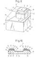
- Fig. 9 is a perspective view illustrating, on an enlarged scale, a portion of the magnetic head slider of Fig. 8.
- Fig. 10 is a sectional view taken along the line X-X of the magnetic head slider of Fig. 8. Note that the magnetic head slider shown in Figs. 8 to 10 is a head slider of the negative pressure type.
- the magnetic head slider 14 comprises the slider body 20 which comprises the base portion 21 and the element-forming portion 22 joined to the base portion 21.
- the base portion 21 is made of an altic material (Al 2 O 3 TiC) and the element-forming portion 22 is made of alumina (Al 2 O 3 ).
- Magnetic converter elements 23 (see Figs. 2 and 3) are fabricated on the element-forming portion 22 through the thin film formation process.
- the magnetic converter elements 23 have magnetic poles 24.
- the arrow A represents an air flow direction relative to the magnetic head slider 14 during operation of the disk device 10.
- the magnetic head slider 14 has a surface (first surface) 26 that faces the magnetic disk 13 during operation.
- the first surface 26 of the magnetic head slider 14 includes a boundary 25 between the element-forming portion 22 and the base portion 21.
- the slider-flying rails 27 are protruding beyond the first surface 26 of the slider body.
- the rails 27 have second surfaces 28.
- the shape of the rails 27 is different from the shape of the rails 27 described referring to Figs. 2 and 3.
- pneumatic bearings 33 are provided protruding beyond the second surfaces 28 of the rails 27.
- the pneumatic bearings 33 have third surfaces 34.
- the magnetic poles 24 appear on the third surfaces 34 of the pneumatic bearings 33.
- a first protection film 29 is formed on the first surface 26 of the slider body 20 covering the boundary 25 between the element-forming portion 22 and the base portion 21.
- Second protection films 30 are formed on the second surfaces 28 of the slider-flying rails 27.
- Third protection films 35 are formed on the third surfaces 34 of the pneumatic bearings 33 to protect the magnetic poles 24 of the magnetic conversion elements 23. Note that, in Fig. 8, the first protection film 29, second protection films 30 and the third protection films 35 are not illustrated.
- the action of the first protection film 29 is the same as the action of the first protection film 29 of the above embodiment, and the action of the second protection films 30 and of the third protection films 35 is the same as the action of the second protection films 30 of the above embodiment. Further, it is preferred that the first protection film 29, second protection films 30 and third protection films 35 are formed from carbon films (e.g., DLC). It is preferred that the thickness of the first protection film 29 is different from the thicknesses of the second protection films 30 and of the third protection films 35. In this case, it is preferred that the thickness of the first protection film 29 is greater than the thickness of the second protection films 30 and the thickness of the third protection films 35.
- the first protection film 29 having a smoother surface on the very small step 31 (see Figs. 4 and 5) produced on the boundary 25 between the element-forming portion 22 and the base portion 21 of the first surface 26 to thereby prevent the deposition of the lubricant on the first surface 26 of the magnetic head slider 14 without increasing the thickness of the magnetic head slider 14 and, hence, realizing the miniatured magnetic head slider 14.
- the first protection film 29, the second protection films 30 and the third protection films 35 are formed from carbon films containing fluorine. In this case, it is preferred that the fluorine content in the first protection film 29 is greater than the fluorine content in the second protection films 30 and in the third protection films 35.
- the slider-flying rails 27 comprise a first rail portion 36 positioned on the upstream side as viewed in the air flows direction A, and two second floating rail portions 37 arranged at the back of the first rail portion 36 maintaining a distance in the transverse direction of the slider body 20.
- the pneumatic bearings 33 are provided on the first rail portion 36 and on the second rail portions 37.
- the first rail portion 36 comprises a transversal component 36A extending in the transverse direction of the slider body 20, and lengthwise components 36B extending in the lengthwise direction of the slider body 20 from both ends of the transversal component 36A.
- a space surrounded by the transversal component 36A and by the lengthwise components 36B have an increased volume.
- a gap extended in the lengthwise direction is produced between the lengthwise components 36B and the second rail portions 37.
- the air can partially pass over the transversal component 36A of the first rail portion 36, flow into the space on the back side and then flow toward the downstream side. Another part of the air can flow along the second rail portions 37 detouring the transversal component 36A and the lengthwise components 36B of the first rail portion 36. A further part of the air can flow into the space between the pair of second rail portions 37 passing through gaps between the lengthwise components 36B and the second rail portions 37, and flows toward the downstream side.
- the pneumatic bearings 33 is subjected to a flying force as a result of generation of the air flow.
- the flying force can act in a direction in which the magnetic head slider 14 separates away from the magnetic disk 13.
- the air passing over the transversal component 36A of the first rail portion 36 and flowing into the space at the back side thereof can produces a negative pressure due to an increased volume of the space.
- the negative pressure can act in a direction in which the magnetic head slider 14 is pulled toward the magnetic disk 13.
- the second surfaces 28 constitute the surfaces of the magnetic head slider 14 (block constituting the magnetic head slider 14).
- first carbon layers (DLC layers) that serve as second protection films 30 are formed on the surfaces (second surfaces 28) of the magnetic head slider 14 via the first adhesion layer.
- second carbon layers (DLC layers) that serve as third protection films 35 are formed on the surfaces of the first carbon layers (DLC layers) via the second adhesion layer.
- the second adhesion layer and the second carbon layers (DLC layers) are etched in the presence of a mask to form the pneumatic bearings 33 and the third protection films 35. The remaining portions of the second adhesion layer can act as the pneumatic bearings 33.
- the first adhesion layer and the second carbon layers (DLC layers) are then etched in the presence of a mask to form the slider-flying rails 27 and the second protection films 30. Etching is carried out to expose the altic layer constituting the base portion 21 and the alumina layer constituting the element-forming portion 22 upon grinding. As a result, the bottom surface of the ground layer becomes lower than the second surfaces 28 to form the first surface 26 of the magnetic head slider 14. Accordingly, the slider-flying rails 27 protrude beyond the first surface 26. Thereafter, the first protection film 29 is formed on the first surface 26 of the magnetic head slider 14. This feature is illustrated in Fig. 10. Therefore, if becomes possible to vary the thicknesses and compositions of the first protection film 29, second protection films 30 and third protection films 35.
- the ends of the slider-flying rails 27 where the magnetic converter elements 23 are positioned are also ground and removed by etching.
- the magnetic poles 24 of the magnetic converter elements 23 can be brought closer to the magnetic disk 13.
- the first protection film 29 is formed up to the rear side of the ends 38 of the rails 27 where the magnetic converter elements 23 are positioned on the first surface 26. Therefore, the lubricant can be prevented from depositing near the positions where the magnetic converter elements 23 are formed.
Landscapes
- Adjustment Of The Magnetic Head Position Track Following On Tapes (AREA)
Abstract
Description
Therefore, the content of fluorine in the first protection film is selected to be greater than the content of fluorine in the second protection films to thereby improve the action of the first protection film for preventing the deposition of lubricant without deteriorating the properties of the second protection films of the slider-flying rails.
Claims (9)
- A magnetic head slider comprising:a slider body comprising a base portion and an element-forming portion joined to said base portion and having formed thereon magnetic conversion elements;a first surface of said slider body that faces a magnetic medium during use of said slider;slider-flying rails protruding beyond the first surface of said slider body and having second surfaces;a first protection film formed on the first surface of the slider body and covering a boundary between said element-forming portion and said base portion; andsecond protection films formed on the second surfaces of said slider-flying rails to protect said magnetic conversion elements.
- A magnetic head slider according to claim 1, wherein the thickness of said first protection film is different from the thickness of said second protection films.
- A magnetic head slider according to claim 2, wherein the thickness of said first protection film is greater than the thickness of said second protection films.
- A magnetic head slider according to claim 1, wherein said first protection film and said second protection film each comprise a carbon film containing fluorine, the content of fluorine in said first protection film being greater than the content of fluorine in said second protection films.
- A magnetic head slider comprising:a slider body comprising a base portion and an element-forming portion joined to said base portion and having formed thereon magnetic conversion elements;a first surface of said slider body that faces a magnetic medium during use of said slider;slider-flying rails protruding beyond the first surface of said slider body and having second surfaces;pneumatic bearing portions protruding beyond the second surfaces of said slider-flying rails and having third surfaces;a first protection film formed on the first surface of the slider body and covering a boundary between said element-forming portion and said base portion;second protection films formed on the second surfaces of said slider-flying rails; andthird protection films formed on the third surfaces of said pneumatic bearings to protect said magnetic conversion elements.
- A magnetic head slider according to claim 5, wherein said slider-flying rails comprise a first rail portion, having a transversal component extending in the transverse direction of said slider body and lengthwise components extending in the lengthwise direction of said slider body from both ends of said transversal component, and two second rail portions arranged at the back of said first rail portion with a distance in the transverse direction of said slider body.
- A magnetic head slider according to claim 6, wherein the thickness of said first protection film is different from the thickness of each of said second and third protection films.
- A magnetic head slider according to claim 7, wherein the thickness of said first protection film is greater than the thickness of each of said second and third protection films.
- A magnetic head slider according to claim 6, wherein said first protection film, said second protection films and said third protection films each comprises a carbon film containing fluorine, the content of fluorine in said first protection film being greater than the content of fluorine in said second and third protection films.
Applications Claiming Priority (1)
| Application Number | Priority Date | Filing Date | Title |
|---|---|---|---|
| PCT/JP2003/001811 WO2004075177A1 (en) | 2003-02-19 | 2003-02-19 | Magnetic head slider |
Publications (2)
| Publication Number | Publication Date |
|---|---|
| EP1596371A1 true EP1596371A1 (en) | 2005-11-16 |
| EP1596371A4 EP1596371A4 (en) | 2008-06-04 |
Family
ID=32894232
Family Applications (1)
| Application Number | Title | Priority Date | Filing Date |
|---|---|---|---|
| EP03815969A Withdrawn EP1596371A4 (en) | 2003-02-19 | 2003-02-19 | MAGNETIC HEAD SLIDER |
Country Status (5)
| Country | Link |
|---|---|
| US (2) | US7154710B2 (en) |
| EP (1) | EP1596371A4 (en) |
| JP (1) | JP4169743B2 (en) |
| AU (1) | AU2003211237A1 (en) |
| WO (1) | WO2004075177A1 (en) |
Cited By (1)
| Publication number | Priority date | Publication date | Assignee | Title |
|---|---|---|---|---|
| US9449623B2 (en) | 2014-06-03 | 2016-09-20 | HGST Netherlands B.V. | Reducing ion migration in a hard disk drive microactuator flexure assembly |
Families Citing this family (9)
| Publication number | Priority date | Publication date | Assignee | Title |
|---|---|---|---|---|
| AU2003211237A1 (en) * | 2003-02-19 | 2004-09-09 | Fujitsu Limited | Magnetic head slider |
| JP4131720B2 (en) * | 2004-08-31 | 2008-08-13 | 富士通株式会社 | Magnetic recording medium, head slider and manufacturing method thereof |
| JP2006107607A (en) * | 2004-10-05 | 2006-04-20 | Hitachi Global Storage Technologies Netherlands Bv | Magnetic head and manufacturing method thereof |
| JP2006107673A (en) * | 2004-10-08 | 2006-04-20 | Shinka Jitsugyo Kk | Magnetic head, manufacturing method thereof, and head suspension assembly |
| US7495865B2 (en) * | 2006-04-10 | 2009-02-24 | Seagate Technology Llc | Adhesion layer for protective overcoat |
| US7948712B2 (en) * | 2006-05-18 | 2011-05-24 | Seagate Technology Llc | Dual thickness carbon overcoat |
| JP2008102989A (en) * | 2006-10-17 | 2008-05-01 | Fujitsu Ltd | Head slider and manufacturing method thereof |
| CN104008756A (en) * | 2013-02-22 | 2014-08-27 | 新科实业有限公司 | Write part, thermally assisted magnetic head slider, magnetic head flap assembly and manufacturing method |
| US11094339B1 (en) * | 2020-04-13 | 2021-08-17 | Seagate Technology Llc | Methods of manufacturing one or more sliders that includes a second lapping process after patterning, and related sliders |
Family Cites Families (18)
| Publication number | Priority date | Publication date | Assignee | Title |
|---|---|---|---|---|
| US5037470A (en) | 1985-12-17 | 1991-08-06 | Isover Saint-Gobain | Nutritive glasses for agriculture |
| JPH0528429A (en) | 1991-07-22 | 1993-02-05 | Fujitsu Ltd | Thin film magnetic head |
| US5433766A (en) | 1992-10-16 | 1995-07-18 | The United States Of America As Represented By The Administrator Of The National Aeronautics And Space Administration | Slow-release fertilizer |
| US5654850A (en) * | 1993-05-18 | 1997-08-05 | Applied Magnetics Corp. | Carbon overcoat with electrically conductive adhesive layer for magnetic head sliders |
| JPH07182628A (en) | 1993-12-21 | 1995-07-21 | Hitachi Ltd | Magnetic head, magnetic storage device, and magnetic disk storage device |
| JPH07230615A (en) | 1994-02-18 | 1995-08-29 | Hitachi Ltd | Thin film magnetic head |
| JPH07312051A (en) | 1994-05-13 | 1995-11-28 | Hitachi Ltd | Method of manufacturing magnetic head slider and magnetic head slider |
| JPH09161223A (en) * | 1995-12-12 | 1997-06-20 | Hitachi Ltd | Thin film magnetic head and magnetic disk recording / reproducing apparatus |
| US5777825A (en) * | 1996-09-04 | 1998-07-07 | International Business Machines Corporation | Negative pressure step pad air bearing design and method for making the same |
| AUPO267896A0 (en) | 1996-09-30 | 1996-10-24 | Hi-Fert Pty. Ltd. | Foliar fertilisers |
| JP2853689B2 (en) | 1996-12-26 | 1999-02-03 | 日本電気株式会社 | Magnetic head |
| JPH11110729A (en) | 1997-10-01 | 1999-04-23 | Alps Electric Co Ltd | Magnetic head and manufacture of the same |
| JP3674347B2 (en) | 1998-09-28 | 2005-07-20 | 富士通株式会社 | Negative pressure head slider |
| US6132485A (en) | 1998-09-28 | 2000-10-17 | Sanders; John Larry | Soil nutrient compositions and methods of using same |
| US6254656B1 (en) | 1999-04-06 | 2001-07-03 | Fuji Silysia Chemical Ltd. | Silica based fertilizer and method for using the same |
| JP2001210037A (en) * | 2000-01-21 | 2001-08-03 | Alps Electric Co Ltd | Magnetic head slider |
| US6939387B2 (en) | 2002-08-19 | 2005-09-06 | Calcuim Silicate Corporation, Inc. | Soil enhancers |
| AU2003211237A1 (en) * | 2003-02-19 | 2004-09-09 | Fujitsu Limited | Magnetic head slider |
-
2003
- 2003-02-19 AU AU2003211237A patent/AU2003211237A1/en not_active Abandoned
- 2003-02-19 WO PCT/JP2003/001811 patent/WO2004075177A1/en not_active Ceased
- 2003-02-19 EP EP03815969A patent/EP1596371A4/en not_active Withdrawn
- 2003-02-19 JP JP2004568475A patent/JP4169743B2/en not_active Expired - Fee Related
-
2005
- 2005-05-12 US US11/127,081 patent/US7154710B2/en not_active Expired - Fee Related
-
2006
- 2006-11-13 US US11/595,955 patent/US20070058297A1/en not_active Abandoned
Cited By (1)
| Publication number | Priority date | Publication date | Assignee | Title |
|---|---|---|---|---|
| US9449623B2 (en) | 2014-06-03 | 2016-09-20 | HGST Netherlands B.V. | Reducing ion migration in a hard disk drive microactuator flexure assembly |
Also Published As
| Publication number | Publication date |
|---|---|
| WO2004075177A1 (en) | 2004-09-02 |
| JP4169743B2 (en) | 2008-10-22 |
| AU2003211237A1 (en) | 2004-09-09 |
| EP1596371A4 (en) | 2008-06-04 |
| US20050201012A1 (en) | 2005-09-15 |
| JPWO2004075177A1 (en) | 2006-06-01 |
| US20070058297A1 (en) | 2007-03-15 |
| US7154710B2 (en) | 2006-12-26 |
Similar Documents
| Publication | Publication Date | Title |
|---|---|---|
| US5617273A (en) | Thin film slider with protruding R/W element formed by chemical-mechanical polishing | |
| US5896243A (en) | Magneto-resistive effect type head with step or protrusion for reducing thermal asperity | |
| US8051552B2 (en) | Stitched wrap around shield fabrication for perpendicular magnetic recording write heads | |
| JP2009048745A (en) | Linear recording type magnetic head assembly and magnetic tape device using the same | |
| US7154710B2 (en) | Magnetic head slider | |
| JP3597664B2 (en) | Method of manufacturing magnetic head | |
| JP2000339619A (en) | Wear resistance magnetic writing head | |
| JPH11306708A (en) | Flying head slider and recording disk device | |
| US7738215B2 (en) | Magnetic head slider having spherical of ellipsoidal projection formed thereon | |
| EP1677291A2 (en) | Disk drive with negative-pitch slider for contact recording | |
| JP2004118995A (en) | Slider base coat for thermal ptr reduction | |
| US7619857B2 (en) | Silicon-made magnetic head slider and method of producing the same | |
| JP2853689B2 (en) | Magnetic head | |
| JP2550516B2 (en) | Levitation type magnetic head | |
| KR100750229B1 (en) | Magnetic head slider | |
| US6754043B2 (en) | Head slider | |
| JP2943696B2 (en) | Thin film magnetic head | |
| JPH0618054B2 (en) | Magnetic head | |
| JP3517673B2 (en) | Slider and rotary disk recorder | |
| CN100354934C (en) | Magnetic head slider | |
| US20050007699A1 (en) | Flying head slider and manufacturing method of the head slider | |
| JPH1049850A (en) | Magnetic disk recording device | |
| JP2762947B2 (en) | Magnetic head and method of manufacturing the same | |
| JP2001236619A (en) | Method for manufacturing slider for thin film magnetic head | |
| WO1998000841A1 (en) | Virtual contact hard disk drive with planar transducer |
Legal Events
| Date | Code | Title | Description |
|---|---|---|---|
| PUAI | Public reference made under article 153(3) epc to a published international application that has entered the european phase |
Free format text: ORIGINAL CODE: 0009012 |
|
| 17P | Request for examination filed |
Effective date: 20050609 |
|
| AK | Designated contracting states |
Kind code of ref document: A1 Designated state(s): AT BE BG CH CY CZ DE DK EE ES FI FR GB GR HU IE IT LI LU MC NL PT SE SI SK TR |
|
| AX | Request for extension of the european patent |
Extension state: AL LT LV MK RO |
|
| DAX | Request for extension of the european patent (deleted) | ||
| RBV | Designated contracting states (corrected) |
Designated state(s): DE FR GB |
|
| A4 | Supplementary search report drawn up and despatched |
Effective date: 20080507 |
|
| 17Q | First examination report despatched |
Effective date: 20080724 |
|
| RAP1 | Party data changed (applicant data changed or rights of an application transferred) |
Owner name: TOSHIBA STORAGE DEVICE CORPORATION |
|
| GRAP | Despatch of communication of intention to grant a patent |
Free format text: ORIGINAL CODE: EPIDOSNIGR1 |
|
| STAA | Information on the status of an ep patent application or granted ep patent |
Free format text: STATUS: THE APPLICATION IS DEEMED TO BE WITHDRAWN |
|
| 18D | Application deemed to be withdrawn |
Effective date: 20100707 |