EP1596197B1 - Method and device for determining the mechanical properties of metals - Google Patents
Method and device for determining the mechanical properties of metals Download PDFInfo
- Publication number
- EP1596197B1 EP1596197B1 EP05102547A EP05102547A EP1596197B1 EP 1596197 B1 EP1596197 B1 EP 1596197B1 EP 05102547 A EP05102547 A EP 05102547A EP 05102547 A EP05102547 A EP 05102547A EP 1596197 B1 EP1596197 B1 EP 1596197B1
- Authority
- EP
- European Patent Office
- Prior art keywords
- sample carrier
- melt
- layer
- adhering
- carrier
- Prior art date
- Legal status (The legal status is an assumption and is not a legal conclusion. Google has not performed a legal analysis and makes no representation as to the accuracy of the status listed.)
- Not-in-force
Links
Images
Classifications
-
- B—PERFORMING OPERATIONS; TRANSPORTING
- B22—CASTING; POWDER METALLURGY
- B22D—CASTING OF METALS; CASTING OF OTHER SUBSTANCES BY THE SAME PROCESSES OR DEVICES
- B22D2/00—Arrangement of indicating or measuring devices, e.g. for temperature or viscosity of the fused mass
-
- G—PHYSICS
- G01—MEASURING; TESTING
- G01N—INVESTIGATING OR ANALYSING MATERIALS BY DETERMINING THEIR CHEMICAL OR PHYSICAL PROPERTIES
- G01N33/00—Investigating or analysing materials by specific methods not covered by groups G01N1/00 - G01N31/00
- G01N33/20—Metals
- G01N33/205—Metals in liquid state, e.g. molten metals
-
- G—PHYSICS
- G01—MEASURING; TESTING
- G01N—INVESTIGATING OR ANALYSING MATERIALS BY DETERMINING THEIR CHEMICAL OR PHYSICAL PROPERTIES
- G01N1/00—Sampling; Preparing specimens for investigation
- G01N1/02—Devices for withdrawing samples
- G01N1/10—Devices for withdrawing samples in the liquid or fluent state
- G01N1/12—Dippers; Dredgers
- G01N1/125—Dippers; Dredgers adapted for sampling molten metals
Definitions
- the invention relates to a method for the determination of mechanical properties, in particular high-temperature properties of materials, preferably of metals, in particular of iron-containing metals, with cast structure, as described e.g. occurs during continuous casting, wherein a sample carrier is immersed in a melt of the material and the solidified on the sample carrier layer of melt on properties, and an apparatus for performing the method.
- High temperature mechanical material properties play a role in the description of all processes that provide stress to the material at high temperatures. These include steel casting, continuous casting, rolling and welding.
- Yamanaka and co-authors performed tensile tests on a solidifying cylindrical block 155 mm in diameter ( Yamanaka, A., K. Nakajima, K. Yasumoto, H. Kawashima, and K. Nakai: excessive evaluation de la contrainte critique de formation des criques internes en coulee continue, La Revue de Metallurgie - CIT, 89 (1992), 627- 633 ).
- the shell thickness at the start of the experiment is about 40 mm and is measured by thermocouples, which are located inside the block.
- the solidifying shell becomes stretching exposed to up to 4%, the elongation is determined optically. After the experiment, internal cracks are detected by sulfur prints.
- Von Wünnenberg and Flender (Wünnenberg, K. and R. Flender: Investigation of Internal-Crack Formation in Continuous Casting, Using a Hot Model, Ironmaking and Steelmaking 12-1 (1985), 22-29) was a block with a height of 715 mm, a width of 500 mm and a thickness of 200 mm, wherein one side of the block is bounded by a water-cooled copper plate, which is removed after about 3 minutes of solidification time. Thereafter, a hydraulically operated punch presses the solidified shell inwards and generates at the phase boundary solid / liquid a defined elongation. Wintz and co-authors ( Wintz, M., M.
- the basic principle of these tests is that a two-part steel test piece is immersed in a molten steel in an induction furnace.
- the test piece may be coated with ceramic materials.
- the heat dissipation is controlled by the type and thickness of the coating.
- a steel shell solidifies on the surface.
- the main crystallization direction is opposite to the direction of heat dissipation, ie normal to the specimen surface.
- the lower test piece part is lowered hydraulically in the induction furnace and the steel shell is subjected to tension.
- force and path are recorded.
- the heating of the specimen is recorded with thermocouples inside. From the measured temperatures, the heat flux density at the specimen surface can be calculated ( Hiebler, H. and C. Bernhard: Mechanical Properties and Crack Susceptibility of Steel during Solidification, steel research 69-9 (1999), 349-355 ). From the measured temperatures, the heat transfer between shell and test specimen is calculated and from this the shell growth and the temperature distribution in the strand shell.
- the disadvantage here is a change in the shell thickness during the experiment, if this exceeds a certain period of time.
- the experimental time is in principle limited to the top, so that here too only examinations in the first toughness minimum close to the solidus temperature of the investigated material can be performed.
- a device for taking a sample of a slag from a liquid molten steel comprising a crucible for receiving a melt and a submerged in the crucible by means of a dipping device and removable sample carrier.
- the invention aims to avoid these disadvantages and difficulties and has as its object to provide a method of the type described in the introduction and an apparatus for carrying out the method, which make it possible to investigate a material with structural and structural properties, the state after the Casting the metal correspond.
- crystalline materials e.g. Of metals, depending on the cooling conditions dependent crystal structure or a conversion of the crystal structure into account.
- sample carrier removed after adhesion of a layer of melt from the melt and adhering to the sample carrier solidified layer of melt is examined in terms of their properties in adhering to the sample carrier state, preferably after cooling to a predetermined temperature.
- the through-solidified layer adhering to the sample carrier is subjected to melt-to-draft, whereby its ductility and / or creep behavior and / or elongation at break and / or toughness and / or tensile strength are determined.
- the process of the invention for a molten steel determines properties in a temperature range of austenite-ferrite transformation.
- a device for carrying out the method with a melting crucible for receiving a melt of a material, a two-part sample carrier which can be immersed in the crucible by means of a dipping device and whose two parts can be moved by means of a force device, and with a carrier receiving the sample carrier and its actuating devices, is characterized in that the carrier and the crucible are separable from each other, in particular by performing a lateral relative movement are moved apart.
- the device according to the invention is expediently characterized by an inert gas protective hood into which the sample carrier can be introduced after being coated with solidified melt or which can be slipped over the sample carrier.
- the device is characterized in that the two parts of the sample carrier during or before immersion in the melt are slightly separated from each other, u.zw. while avoiding the ingress of melt between the two parts of the sample carrier, preferably using a lip seal and / or an asbestos seal.
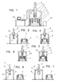
- Fig. 1 shows an apparatus according to the invention in an overall view; the Fig. 2 to 8 illustrate in each case too Fig. 1 analog representation of the procedure.
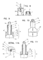
- Fig. 9 shows a sample carrier in section and Fig. 10 the same after carrying out an examination.
- Fig. 11 and detail 11A show a modified embodiment of the sample carrier for determining the shrinkage behavior of materials.
- steel turns out to be critical in terms of its surface crack sensitivity when cast on conventional continuous casters.
- a temperature range between 800 and 1000 ° C even slight strains, such as occur when straightening a curved strand in a circular arc caster, for the formation of surface cracks
- a quantification of the influence of the analysis on the ductility properties is not possible.
- the effects of the underlying experimental conditions in the known investigations, such as load type and temperature control are controversial.
- the device shown has a crucible on an induction furnace 1, in which a molten metal 2, such as molten steel, is located.
- a molten metal 2 such as molten steel
- On a support 3 is a two-part sample carrier 4, as he eg in the FIGS. 9 and 11 is shown attached.
- This sample carrier 4 can be raised and lowered by means of a lifting and lowering device 5, for example designed as a hydraulic pressure medium cylinder, wherein the pressure medium cylinder 5 is mounted on the support 3 and is mounted with this on a movable from the field of induction furnace 1 trolley 6.
- the trolley 6 can also be replaced by another device, such as a crane or the like. It is essential that the sample carrier 4 can not only be moved out of the induction furnace 1, but also can be brought to the side of him for the actual determination of the mechanical properties of the metal in position.
- the sample carrier 4 itself consists of two parts, u.zw. a piston-like lower part 4 'and a piston-like upper part 4 ", wherein the upper part 4" relative to the lower part 4' or vice versa, the lower part 4 'with respect to the upper part 4 "is relatively movable, u.zw. to each other and movable from each other, for example, betechnikstelligbar in that both parts have longitudinal extensions 7, 8, wherein the longitudinal extension 7 of the lower part 4 'passes through the longitudinal extension 8 of the upper part 4 "and is connected to a pressure medium cylinder 9 causing the relative movement between lower and upper part, for example with a threaded end part 10 with the pressure medium cylinder 9 is bolted.
- the longitudinal extension 8 of the upper part 4 likewise has a threaded end part 11 with which it is likewise screwed to the pressure medium cylinder 9.
- Both the pressure medium cylinder 5 for moving the sample carrier 4 up and down and the pressure medium cylinder 9 for applying a force between the upper and lower part of the sample carrier 4 can be replaced by rack, Gewindeantrieb-, adjusting spindles, etc.
- thermocouples 13 are located about the longitudinal axis 14 of the sample carrier 4 opposite each other about 2 mm below the surface 15 They are used to detect the local temperature history when carrying out a test, for example Ni-Cr-Ni thermocouples can be used as thermocouples 13.
- Both the upper part 4 "and the lower part 4 ' have the same outer cross section and are coated on their peripheral surface with a ceramic layer 16. This serves to regulate the heat dissipation between the sample carrier 4 and the metal to be examined
- the ceramic layer 16 is selected according to the application and depending on the metal to be tested. Likewise, the dimensions of the sample carrier 4 are adapted to the type of test (tensile, creep, relaxation or shrinkage test).
- the sample carrier 4 may be e.g. be made of Ni-alloyed or heat-resistant steel.
- a measuring device 17 with a computer 18 is illustrated. Further shows Fig. 1 an inert gas protective hood 19 which can be connected to an inert gas supply line and into which the sample carrier 4 can be inserted or which can be pushed over the sample carrier 4.
- a melt 2 is prepared in the induction furnace 1 ( Fig. 2 ), whereupon the sample carrier 4 is mounted and the test parameters are set.
- the trolley 6 is still the side of the induction furnace 1.
- the trolley 6 is placed over the induction furnace 1 in position ( Fig. 3 ) and the sample carrier 4 immersed in the melt 2 ( Fig. 4 ).
- a test specimen 20, formed by a solidified on the sample carrier 4 layer the melt 2 whereupon the sample carrier 4 with the test piece 20 is lifted out of the induction furnace 1 ( Fig. 5 ) and the side of the induction furnace 1 by means of the trolley 6 is spent ( Fig. 6 ).
- the inert gas protective hood 19 is slipped over the test body 20, and the experiment, for example a tensile test, can be carried out ( Fig. 7 ). After the end of the tensile test and sufficient cooling of the test specimen 20, the inert gas protective cover 19 is removed ( Fig. 8 ), and it may optionally after dismantling of the sample carrier 4, the fracture surfaces or any surface cracks, - the structure, etc. are examined in more detail.
- FIG. 11 shows an embodiment of the sample carrier 4 for the performance of a shrinkage test.
- the lower part 4 'against the upper part 4 "displaced, by the shrinkage behavior of adhering to the sample carrier 4 layer of melt 2.
- the lower part 4 In order to ensure proper functioning of the Gegenpulverschiebens of the two parts 4' and 4" is between the upper part. 4 "and the lower part 4 'a sealing cord 21 made of asbestos inserted, which is housed in a recess 22 of the upper part 4".
- the upper part 4 overlaps the sealing cord 21 peripherally with a type of sealing lip 23.
- the device With the device according to the invention, one can carry out a large number of tests immediately under successive identical conditions, wherein the chemical composition of the melt 2 can be changed by alloying between the individual experiments.
- the device can be used for a variety of materials, e.g. also for aluminum casting, magnesium casting, special alloys etc. find use.
- test parameters of a specific experiment are listed below by way of example.
- the experiments can be carried out in various ways.
- the selection of the test parameters is adapted to the material data to be examined.
- the reproduced parameters represent only one of the many possibilities.
Landscapes
- Chemical & Material Sciences (AREA)
- Engineering & Computer Science (AREA)
- Health & Medical Sciences (AREA)
- Life Sciences & Earth Sciences (AREA)
- Analytical Chemistry (AREA)
- Food Science & Technology (AREA)
- Medicinal Chemistry (AREA)
- Physics & Mathematics (AREA)
- Mechanical Engineering (AREA)
- Biochemistry (AREA)
- General Health & Medical Sciences (AREA)
- General Physics & Mathematics (AREA)
- Immunology (AREA)
- Pathology (AREA)
- Investigating And Analyzing Materials By Characteristic Methods (AREA)
- Sampling And Sample Adjustment (AREA)
Description
Die Erfindung betrifft ein Verfahren zur Ermittlung von mechanischen Eigenschaften, insbesondere Hochtemperatureigenschaften von Werkstoffen, vorzugsweise von Metallen, insbesondere von eisenhältigen Metallen, mit Gußstruktur, wie sie z.B. beim Stranggießen auftritt, wobei ein Probenträger in eine Schmelze des Werkstoffes getaucht und die am Probenträger erstarrte Schicht aus Schmelze auf Eigenschaften untersucht wird, sowie eine Vorrichtung zur Durchführung des Verfahrens.The invention relates to a method for the determination of mechanical properties, in particular high-temperature properties of materials, preferably of metals, in particular of iron-containing metals, with cast structure, as described e.g. occurs during continuous casting, wherein a sample carrier is immersed in a melt of the material and the solidified on the sample carrier layer of melt on properties, and an apparatus for performing the method.
Mechanische Hochtemperaturwerkstoffeigenschaften spielen bei der Beschreibung aller Prozesse eine Rolle, die eine Belastung bzw. Verformung des Werkstoffs bei hohen Temperaturen vorsehen. Dazu zählen bei der Stahlherstellung das Stranggießen, das Walzen und das Schweißen.High temperature mechanical material properties play a role in the description of all processes that provide stress to the material at high temperatures. These include steel casting, continuous casting, rolling and welding.
In Bezug auf das Stranggießen ist besonders die Duktilität des Werkstoffs und deren Abhängigkeit von Stahlzusammensetzung und Temperatur von Interesse, da man sich Aufschlüsse über die Bildung von Rissen erhofft. Die Festigkeit des Stahls bei hohen Temperaturen ist für die Auslegung von Stranggießmaschinen maßgeblich, die Bestimmung von Kriechgesetzen erlangt mit der Entwicklung der numerischen Simulation zunehmende Bedeutung.With regard to continuous casting, the ductility of the material and its dependence on the steel composition and temperature are of particular interest, since information about the formation of cracks is expected. The strength of the steel at high temperatures is crucial for the design of continuous casting machines, the determination of creep laws is becoming increasingly important with the development of numerical simulation.
Der überwiegende Teil der Laboruntersuchungen wird mit konventionellen Heißzugapparaturen durchgeführt, die eine induktive Erwärmung oder eine Widerstandserwärmung der Probe vorsehen. Von Schwerdtfeger stammt eine Zusammenfassung dieser Arbeiten (Schwerdtfeger, K.: Rißanfälligkeit von Stählen beim Stranggießen und Warmumformen, Verlag Stahleisen, Düsseldorf 1994), die unter anderem die mangelnde Umsetzbarkeit der Ergebnisse in die Praxis bemängelt. Unterschiedliche Versuchsbedingungen, wie Temperaturführung, Dehnrate und Probengeometrie, führen zu einer breiten Streuung der Ergebnisse. Besonders klar konnte dies für unterschiedliche Temperaturzyklen gezeigt werden: Bereits in den 1970er Jahren führten Wilber et al. (Wilber, G.A. et al.: The Effect of Thermal History and Composition on the Hot Ductility of Low Carbon Steel, Met. Trans. A, 6a (1975), 1727 - 1735) und Palmaers (Palmaers, A. : High Temperature Mechanical Properties of Steel as a Means for Controlling Continuous Casting, CRM, No. 53, November 1978, 23 - 31) vergleichende Untersuchungen an Proben durch, die vor dem Zugversuch auf Raumtemperatur abgekühlt und in verschiedenen Zyklen wiedererwärmt wurden, oder andererseits aus dem flüssigen Zustand "in-situ" abgekühlt und getestet wurden. Es zeigten sich deutliche Unterschiede in der jeweils ermittelten Brucheinschnürung, die durch die mehrmalige Umkristallisation und die daraus folgenden Unterschiede im Gefüge begründet wurden. Die Probleme in Hinblick auf die Verwendung der Ergebnisse für die Beschreibung des Stranggießprozesses wurden ausführlich von Lankford diskutiert (
Aus diesem Grund wurden Versuche mit Stranggießrelevanz zunehmend "in-situ", also nach Aufschmelzen und Erstarren der Probe in einem Quarzglasröhrchen, durchgeführt. Durch radiales Anblasen der Oberfläche mit Stickstoff konnte auch eine normal auf die Hauptspannungsrichtung orientierte Kristallisationsrichtung erreicht werden (Hertel, J., H. Litterscheidt, U. Lotter und H. Pircher: Laboratory Simulation of Strand Shell Stresses and Strains during Continuous Casting, Thyssen Technische Berichte, Heft 1/91, 31-42). Die Wärmeabfuhr kann jedoch durch das Quarzglasröhrchen nicht beliebig erhöht werden.For this reason, tests with continuous casting relevance were increasingly carried out "in situ", ie after melting and solidification of the sample in a quartz glass tube. By radially blowing the surface with nitrogen, it was also possible to achieve a direction of crystallization oriented normal to the principal direction of stress (Hertel, J., H. Litterscheidt, U. Lotter and H. Pircher: Laboratory Simulation of Strand Shell Stresses and Strains during Continuous Casting, Thyssen Technical Reports,
Zu den Nachteilen der konventionellen Heißzugeinrichtungen ist zu zählen, dass die Bestimmung der Brucheinschnürung lediglich eine qualitative Aussage über Bereiche mit verminderter Zähigkeit gibt und keine Aussage liefert, bei welcher Belastung es bereits zu partieller Rissbildung kommt.One of the disadvantages of conventional hot tipping equipment is that the determination of the fracture waist only gives a qualitative statement about areas with reduced toughness and does not provide any information on which load already partial cracking occurs.
Dazu kommt, dass die produzierte Struktur nur eingeschränkt jener einer Stranggießschale entspricht. Qualitative Vergleiche zwischen Strukturparametern von Versuchsproben und stranggegossenem Material sind bisher nicht bekannt.In addition, the structure produced only to a limited extent corresponds to that of a continuous casting dish. Qualitative comparisons between structural parameters of experimental samples and continuously cast material are not yet known.
Für den Stranggießprozess sind jedoch besonders kritische Dehnungswerte von Interesse, weshalb andere Versuchsanordnungen entwickelt wurden, die sich in Zug- und Biegeversuche einteilen lassen (
Yamanaka und Mitautoren führten Zugversuche an einem erstarrenden zylindrischen Block mit einem Durchmesser 155 mm durch (
Von Wünnenberg und Flender (Wünnenberg, K. und R. Flender: Investigation of Internal-Crack Formation in Continuous Casting, Using a Hot Model, Ironmaking and Steelmaking 12-1 (1985), 22-29) wurde ein Block mit einer Höhe von 715 mm, einer Breite von 500 mm und einer Dicke von 200 mm vergossen, wobei eine Seite des Blocks von einer wassergekühlten Kupferplatte begrenzt wird, die nach etwa 3 min Erstarrungszeit entfernt wird. Danach drückt ein hydraulisch betriebener Stempel die erstarrte Schale nach innen und erzeugt an der Phasengrenze fest/flüssig eine definierte Dehnung. Wintz und Mitautoren (
Ein Nachteil der Biegeversuche ist, dass die auftretenden Dehnungen nur berechnet werden können, da sie für eine Messung nicht zugänglich sind. Die Qualität der Ergebnisse ist deshalb auch mit der Qualität der rechnerischen Beschreibung des Versuchs verbundenA disadvantage of the bending tests is that the strains that occur can only be calculated because they are not accessible for a measurement. The quality of the results is therefore also connected with the quality of the computational description of the experiment
Eine weiterer Versuchsaufbau zur Untersuchung von mechanischen Hochtemperatureigenschaften und der Rissanfälligkeit von Metallen stammt von Kurz und Mitautoren(
Grundprinzip dieser Versuche ist, dass ein zweigeteilter Prüfkörper aus Stahl in eine in einem Induktionsofen befindliche Stahlschmelze eintaucht. Der Prüfkörper kann mit keramischen Materialien beschichtet sein. Die Wärmeabfuhr wird über Art und Dicke der Beschichtung kontrolliert.The basic principle of these tests is that a two-part steel test piece is immersed in a molten steel in an induction furnace. The test piece may be coated with ceramic materials. The heat dissipation is controlled by the type and thickness of the coating.
Während einer Haltezeit erstarrt an der Oberfläche eine Stahlschale. Die Hauptkristallisationsrichtung liegt entgegengesetzt der Richtung der Wärmeabfuhr, d.h. normal auf die Prüfkörperoberfläche. Nach Ende der Haltezeit wird im Induktionsofen der untere Prüfkörperteil hydraulisch abgesenkt und die Stahlschale auf Zug beansprucht. Während des Zugversuchs werden Kraft und verfahrener Weg aufgezeichnet. Die Erwärmung des Prüfkörpers wird mit Thermoelementen im Inneren aufgezeichnet. Aus den gemessenen Temperaturen lässt sich die Wärmestromdichte an der Prüfkörperoberfläche berechnen (
Die metallografische Untersuchung der Probe nach dem Versuch gestattet eine Aussage über das Auftreten von Rissen und das Ausmaß der Rissbildung (
- Struktur und Gefüge entsprechen jener einer stranggegossenen Schale;
- die Belastung erfolgt normal auf die Hauptkristallisationsrichtung, also unter stranggießähnlichen Bedingungen;
- Wärmeabfuhr ist innerhalb des Bereichs konventioneller und endabmessungsnaher Gießverfahren veränderbar;
- Rissbildung kann quantifiziert und den Versuchsbedingungen oder der Stahlzusammensetzung zugeordnet werden;
- der Aufwand zur Durchführung von Versuchen ist vergleichsweise gering.
- Structure and structure correspond to those of a continuously cast shell;
- the load is normal to the main crystallization direction, ie under continuous casting conditions;
- Heat dissipation is changeable within the range of conventional and close-to-final casting methods;
- Cracking can be quantified and assigned to the experimental conditions or the steel composition;
- the effort to carry out experiments is relatively low.
Nachteilig hierbei ist eine Änderung der Schalendicke während des Versuches, wenn dieser eine bestimmte Zeitspanne überschreitet. Die Versuchszeit ist prinzipiell nach oben begrenzt, sodass auch hierbei ausschließlich Untersuchungen im ersten Zähigkeitsminimum nahe der Solidustemperatur des untersuchten Werkstoffes durchgeführt werden können.The disadvantage here is a change in the shell thickness during the experiment, if this exceeds a certain period of time. The experimental time is in principle limited to the top, so that here too only examinations in the first toughness minimum close to the solidus temperature of the investigated material can be performed.
Aus der Schrift
Zusammenfassend kann gesagt werden, dass während der letzten Jahrzehnte zahlreiche Anstrengungen unternommen wurden, einen prozessnahen Laborversuch zur Simulation der Belastung einer erstarrenden Strangschale beim Stranggießen zu entwickeln. Konventionelle Heißzugversuche weisen das Manko der mangelnden Übereinstimmung der Mikrostruktur der Probe mit jener eines Gussprodukts auf. Die Belastung der Probe bis zum vollständigen Zerreißen liefert mit der Brucheinschnürung zwar einen qualitativen Hinweis auf die Rissempfindlichkeit, die Ableitung eines Verformungslimits ist jedoch schwierig.In summary, numerous efforts have been made in recent decades to develop a near-to-process laboratory test to simulate the stress of a solidifying strand shell during continuous casting. Conventional hot tensile tests have the drawback of the mismatch of microstructure of the sample with that of a cast product. Although the load on the sample until complete rupture provides a qualitative indication of the crack sensitivity with the fracture constriction, the derivation of a deformation limit is difficult.
Prozessnähere Zug- und Biegeversuche sind vergleichsweise aufwendig und auf den Bereich des ersten Zähigkeitsminimums beschränkt.Process-related tensile and bending tests are comparatively complicated and limited to the range of the first toughness minimum.
Die Erfindung bezweckt die Vermeidung dieser Nachteile und Schwierigkeiten und stellt sich die Aufgabe, ein Verfahren der einleitend beschriebenen Art sowie eine Vorrichtung zur Durchführung des Verfahrens zu schaffen, welche es ermöglichen, einen Werkstoff mit Gefüge- und Struktureigenschaften zu untersuchen, die dem Zustand nach dem Vergießen des Metalles entsprechen. Insbesondere soll eine beim Erstarren von kristallinen Werkstoffen, wie z.B. von Metallen, von den Abkühlbedingungen abhängige Kristallstruktur bzw. eine Umwandlung der Kristallstruktur Berücksichtigung finden.The invention aims to avoid these disadvantages and difficulties and has as its object to provide a method of the type described in the introduction and an apparatus for carrying out the method, which make it possible to investigate a material with structural and structural properties, the state after the Casting the metal correspond. In particular, when solidifying crystalline materials, e.g. Of metals, depending on the cooling conditions dependent crystal structure or a conversion of the crystal structure into account.
Diese Aufgabe wird erfindungsgemäß dadurch gelöst, dass der Probenträger nach Anhaften einer Schicht von Schmelze aus der Schmelze entnommen und die am Probenträger haftende durcherstarrte Schicht von Schmelze hinsichtlich ihrer Eigenschaften im am Probenträger haftenden Zustand untersucht wird, vorzugsweise nach Abkühlung auf eine vorbestimmte Temperatur.This object is achieved in that the sample carrier removed after adhesion of a layer of melt from the melt and adhering to the sample carrier solidified layer of melt is examined in terms of their properties in adhering to the sample carrier state, preferably after cooling to a predetermined temperature.
Wesentlich ist hierbei, daß die am Probenträger haftende Schicht von Schmelze während der Prüfung durcherstarrt ist und nicht mit noch flüssiger Schmelze in Kontakt steht. Hierdurch ist es möglich, die Untersuchung der mechanischen Eigenschaften dann durchzuführen, wenn die durcherstarrte Schicht von Schmelze den für die Untersuchung relevanten Temperaturbereich erreicht hat.It is essential here that the adhering to the sample carrier layer of melt is solidified during the test and is not in contact with still liquid melt. This makes it possible to carry out the investigation of the mechanical properties when the solidified layer of melt has reached the relevant temperature range for the investigation.
Vorzugsweise wird die am Probenträger haftende durcherstarrte Schicht von Schmelze auf Zug beansprucht, wobei deren Duktilität und/oder Kriechverhalten und/oder Bruchdehnung und/oder Zähigkeit und/oder Zugfestigkeit ermittelt wird.Preferably, the through-solidified layer adhering to the sample carrier is subjected to melt-to-draft, whereby its ductility and / or creep behavior and / or elongation at break and / or toughness and / or tensile strength are determined.
Mit Hilfe des erfindungsgemäßen Verfahrens ist es auch möglich, an der am Probenträger anhaftenden Schicht das Schrumpfverhalten derselben zu ermitteln.With the aid of the method according to the invention, it is also possible to determine the shrinkage behavior of the layer adhering to the sample carrier.
Um eine nähere Untersuchung von auftretenden Rissen bzw. Bruchstellen ohne Verzunderungen etc. zu ermöglichen, wird zweckmäßig nach dem Entnehmen des Probenträgers aus der Schmelze der Probenträger mit der daran erstarrten Schmelze vor Ermittlung deren Eigenschaften mit Inertgas umgeben.In order to allow a closer examination of occurring cracks or breakages without scaling, etc., it is expedient after removal of the sample carrier from the melt of the sample carrier with the melt solidified before determining their properties surrounded with inert gas.
Vorzugsweise werden mit dem erfindungsgemäßen Verfahren für eine Stahlschmelze Eigenschaften in einem Temperaturbereich der Austenit-Ferrit-Umwandlung bestimmt.Preferably, the process of the invention for a molten steel determines properties in a temperature range of austenite-ferrite transformation.
Eine Vorrichtung zur Durchführung des Verfahren mit einem Schmelztiegel zur Aufnahme einer Schmelze eines Werkstoffes, einem in den Schmelztiegel mittels einer Tauchvorrichtung eintauchbaren sowie heraushebbaren zweiteiligen Probenträger, dessen beide Teile mittels einer Krafteinrichtung voneinander bewegbar sind, sowie mit einem den Probenträger sowie dessen Betätigungseinrichtungen aufnehmenden Träger, ist dadurch gekennzeichnet, dass der Träger und der Schmelztiegel voneinander trennbar, insbesondere unter Durchführung einer seitlichen Relativbewegung auseinanderbewegbar sind.A device for carrying out the method with a melting crucible for receiving a melt of a material, a two-part sample carrier which can be immersed in the crucible by means of a dipping device and whose two parts can be moved by means of a force device, and with a carrier receiving the sample carrier and its actuating devices, is characterized in that the carrier and the crucible are separable from each other, in particular by performing a lateral relative movement are moved apart.
Um Veränderungen an der am Probenträger anhaftenden Schicht von Schmelze während und/oder nach dem Prüfverfahren zu vermeiden, ist die erfindungsgemäße Vorrichtung zweckmäßig gekennzeichnet durch eine Inertgasschutzhaube, in die der Probenträger nach dem Überziehen mit erstarrter Schmelze einbringbar bzw. die über den Probenträger stülpbar ist.In order to avoid changes to the layer of melt adhering to the sample carrier during and / or after the test method, the device according to the invention is expediently characterized by an inert gas protective hood into which the sample carrier can be introduced after being coated with solidified melt or which can be slipped over the sample carrier.
Zur Ermittlung des Schrumpfverhaltens ist die Vorrichtung dadurch gekennzeichnet, dass die zwei Teile des Probenträgers beim oder vor dem Eintauchen in die Schmelze voneinander geringfügig trennbar sind, u.zw. unter Vermeidung des Eindringens von Schmelze zwischen die beiden Teile des Probenträgers, vorzugsweise unter Anwendung einer Lippendichtung und/oder einer Asbestdichtung.To determine the shrinkage behavior, the device is characterized in that the two parts of the sample carrier during or before immersion in the melt are slightly separated from each other, u.zw. while avoiding the ingress of melt between the two parts of the sample carrier, preferably using a lip seal and / or an asbestos seal.
Die Erfindung ist nachfolgend anhand eines Ausführungsbeispieles näher erläutert, das in der Zeichnung schematisch dargestellt ist.
Beim Erstarren von kristallinen Werkstoffen, wie zum Beispiel von Metallen, stellt sich eine von den Abkühlbedingungen abhängige Kristallstruktur ein. Für einen Großteil der industrierelevanten Gießprozesse gilt, dass die thermische Energie über die Bauteiloberflächen abgeführt wird. Unter Vernachlässigung von Strömungseinflüssen ergibt sich auf Grund der gerichteten Wärmeabfuhr ein Kristallwachstum, das der Wärmeabfuhrrichtung entgegengesetzt ist. Die dabei entstehende Struktur wird kolumnare Gussstruktur genannt. Dies trifft auch für die Gussstruktur eines beim Brammenstrangguss erstarrten Stahls zu.When solidifying crystalline materials, such as metals, a dependent on the cooling conditions crystal structure sets. For a large part of the industry-relevant casting processes, the thermal energy is dissipated via the component surfaces. Neglecting flow influences, due to the directed heat dissipation, a crystal growth results, which is opposite to the heat dissipation direction. The resulting structure is called a columnar cast structure. This also applies to the cast structure of a steel solidified in continuous slab casting.
Auf Grund dieser Ausrichtung des Kristallwachstums ergeben sich anisotrope mechanische Werkstoffeigenschaften, insbesondere der Werkstofffestigkeit und damit für das Werkstoffversagen, solange die Kristalle in ihrer Gussstruktur vorliegen. Erfolgt bei weiterer Abkühlung des Gussteils eine Phasenumwandlung, wie z.B. bei Stahl die Austenit-Ferrit-Umwandlung, so werden die Materialeigenschaften von der neu entstandenen Kristallstruktur und deren Phasen dominiert.Due to this orientation of the crystal growth, anisotropic mechanical material properties result, in particular the material strength and thus the material failure, as long as the crystals are present in their casting structure. If, on further cooling of the casting, a phase transformation occurs, e.g. For steel, the austenite-ferrite transformation, the material properties are dominated by the newly formed crystal structure and its phases.
So z.B. erweist sich Stahl beim Vergießen auf konventionellen Stranggießanlagen als kritisch bezüglich seiner Oberflächenrissempfindlichkeit. In einem Temperaturbereich zwischen 800 und 1000°C führen schon geringe Dehnungen, wie sie z.B. beim Richten eines gekrümmten Strangs in einer Kreisbogenstranggießanlage auftreten, zur Bildung von Oberflächenrissen Aus der bestehenden Literatur sind qualitative Aussagen über die Auswirkung verschiedener Legierungs- und Begleitelemente auf die Duktilitätseigenschaften von Stahl bekannt. Eine Quantifizierung des Analyseneinflusses auf die Duktilitätseigenschaften ist jedoch nicht möglich. Weiters sind die Auswirkungen der bei den bekannten Untersuchungen zugrundeliegenden Versuchsbedingungen, wie z.B. Belastungsart und Temperaturführung, umstritten.For example, steel turns out to be critical in terms of its surface crack sensitivity when cast on conventional continuous casters. In a temperature range between 800 and 1000 ° C even slight strains, such as occur when straightening a curved strand in a circular arc caster, for the formation of surface cracks From the existing literature are qualitative statements about the effect of various alloying and accompanying elements on the ductility properties of Steel known. However, a quantification of the influence of the analysis on the ductility properties is not possible. Furthermore, the effects of the underlying experimental conditions in the known investigations, such as load type and temperature control, are controversial.
Im Rahmen der Erfindung ist es u.a. möglich, ausgewählte Stahlsorten mit Hilfe der in
Die in
Der Probenträger 4 selbst besteht aus zwei Teilen, u.zw. einem kolbenartigen Unterteil 4' und einem kolbenartigen Oberteil 4", wobei der Oberteil 4" gegenüber dem Unterteil 4' oder umgekehrt der Unterteil 4' gegenüber dem Oberteil 4" relativbeweglich ist, u.zw. zueinander und voneinander bewegbar. Das ist beispielsweise dadurch bewerkstelligbar, dass beide Teile Längsfortsätze 7, 8 aufweisen, wobei der Längsfortsatz 7 des Unterteiles 4' den Längsfortsatz 8 des Oberteiles 4" durchsetzt und mit einem die Relativbewegung zwischen Unter- und Oberteil verursachenden Druckmittelzylinder 9 verbunden ist, beispielsweise mit einem Gewindeendteil 10 mit dem Druckmittelzylinder 9 verschraubt ist.The
Der Längsfortsatz 8 des Oberteiles 4" weist ebenfalls einen Gewindeendteil 11 auf, mit dem er ebenfalls mit dem Druckmittelzylinder 9 verschraubt ist. Durch Betätigen des Druckmittelzylinders 9 läßt sich somit die Relativbewegung zwischen Ober- 4" und Unterteil 4' durchführen.The
Zur exakten Bestimmung der bei der Versuchsdurchführung auftretenden bzw. auf den Probenträger aufgebrachten bzw. auf ihn von Seiten des zu prüfenden Metalles einwirkenden Kräfte ist zweckmäßig eine Kraftmeßdose 12 vorgesehen.For the exact determination of the forces occurring in the course of the experiment or applied to the sample carrier or acting on it from the side of the metal to be tested, it is expedient to provide a
Sowohl der Druckmittelzylinder 5 zum Auf- und Abbewegen des Probenträgers 4 als auch der Druckmittelzylinder 9 zur Aufbringung einer Kraft zwischen Ober- und Unterteil des Probenträgers 4 können durch Zahnstangen-, Gewindeantrieb-, Stellspindeln etc. ersetzt sein.Both the
Die Querschnitte sowohl des Unterteiles 4' als auch des Oberteiles 4" des Probenträgers 4 sind vorzugsweise kreisförmig. Im Unterteil 4' sind Thermoelemente 13 untergebracht. Die Thermoelemente 13 befinden sich um die Längsachse 14 des Probenträgers 4 einander gegenüberliegend etwa 2 mm unter der Oberfläche 15 des Unterteiles 4'. Sie dienen dazu, die lokale Temperaturgeschichte bei Durchführung einer Prüfung zu erfassen. Als Thermoelemente 13 können z.B. Ni-Cr-Ni-Thermoelemente verwendet werden.The cross-sections of both the lower part 4 'and the
Sowohl der Oberteil 4" als auch der Unterteil 4' weisen ein- und denselben Außenquerschnitt auf und sie sind an ihrer Umfangsfläche mit einer Keramikschicht 16 beschichtet. Diese dient dazu, die Wärmeabfuhr zwischen dem Probenträger 4 und dem zu untersuchenden Metall zu regeln. Die Dicke der Keramikschicht 16 wird je nach Anwendungsfall und je nach zu prüfendem Metall gewählt. Ebenso sind die Abmessungen des Probenträgers 4 an die Versuchsart (Zug-, Kriech-, Relaxations- oder Schrumpfversuch) angepaßt.Both the
Abhängig von den thermischen und mechanischen Prüfanforderungen kann der Probenträger 4 z.B. aus Ni-legiertem oder warmfestem Stahl hergestellt sein.Depending on the thermal and mechanical testing requirements, the
In
Anhand der
Zunächst wird in dem Induktionsofen 1 eine Schmelze 2 vorbereitet (
Anschließend wird über den Prüfkörper 20 die Inertgas-Schutzhaube 19 gestülpt, und es kann der Versuch, beispielsweise ein Zugversuch, durchgeführt werden (
Mit der erfindungsgemäßen Vorrichtung kann man eine Vielzahl von Versuchen unter stets gleichen Bedingungen unmittelbar nacheinander durchführen, wobei die chemische Zusammensetzung der Schmelze 2 zwischen den einzelnen Versuchen durch Legieren verändert werden kann. Die Vorrichtung kann für verschiedenartige Materialien, wie z.B. auch für Aluminiumguss, Magnesiumguss, Sonderlegierungen etc. Verwendung finden.With the device according to the invention, one can carry out a large number of tests immediately under successive identical conditions, wherein the chemical composition of the
Zur Veranschaulichung des Versuchsablaufes sind nachfolgend beispielhaft die Versuchsparameter eines konkret durchgeführten Versuches aufgelistet. Die Versuche lassen sich in verschiedenster Art und Weise durchführen. Die Auswahl der Versuchsparameter wird an die zu untersuchenden Werkstoffdaten angepasst. Die wiedergegebenen Parameter stellen nur eine der vielen Möglichkeiten dar.To illustrate the experimental procedure, the experimental parameters of a specific experiment are listed below by way of example. The experiments can be carried out in various ways. The selection of the test parameters is adapted to the material data to be examined. The reproduced parameters represent only one of the many possibilities.
• Chemische Analyse der Schmelze 2: (Angaben in Massenprozent)
• Schmelztemperatur: 1550 °C
• Liquidustemperatur: 1515 °C
• Stahlschmelze im Induktionsofen 1:
- Durchmesser: 130 mm
- Badtiefe: 300 mm
•
•
• Eintauchzeit des Probenträgers 4: 2 sek
• Eintauchtiefe des Probenträgers 4: 95 mm
• Haltezeit im Induktionsofen 1: 1 sek
• Austauchzeit: 2 sek
• Inertgasspülung: Ar
• Inertgasmenge: 50l/min
• mittlere anerstarrte Schalenstärke des Prüfkörpers 20: 4,2 mm
• Haltezeit bis zum Beginn des Zugversuches: 20 sek.
• Versuchstemperatur:
- Außen:
- Zugversuchstarttemperatur: 789 °C
- Zugversuchendtemperatur: 687 °C
- Innen:
- Zugversuchstarttemperatur: 560 °C
- Zugversuchendtemperatur: 580 °C
• Zugversuch:
- Dauer: 16 sek
- Dehnrate: 0,3 mm/sek
- Gesamtdehnungsweg: 4,8 mm
- Maximalkraft: 26,35 kN
• Rissbildung: Die anerstarrte Stahlschale ist bei diesem Versuch vollständig durchgerissen. Der Riss verlief entlang der Teilungsebene des Probenträgers 4 normal zur Zugrichtung.
• Chemical analysis of the melt 2: (in percentage by mass)
• Melting temperature: 1550 ° C
• Liquidus temperature: 1515 ° C
• molten steel in the induction furnace 1:
- Diameter: 130 mm
- Bath depth: 300 mm
•
•
• Dipping time of the sample holder 4: 2 sec
• Immersion depth of the sample holder 4: 95 mm
• Holding time in the induction furnace 1: 1 sec
• Replacement time: 2 sec
Inert gas purge: Ar
Inert gas quantity: 50l / min
• Average solidified shell thickness of specimen 20: 4.2 mm
• Holding time until the start of the tensile test: 20 sec.
• test temperature:
- Outside:
- Tensile test starting temperature: 789 ° C
- Tensile test temperature: 687 ° C
- Inside:
- Tensile test starting temperature: 560 ° C
- Tensile test temperature: 580 ° C
Tensile test:
- Duration: 16 sec
- Strain rate: 0.3 mm / sec
- Total expansion travel: 4.8 mm
- Maximum force: 26.35 kN
• Cracking: The solidified steel shell is completely torn in this experiment. The crack ran along the dividing plane of the
Claims (9)
- Method for determining mechanical properties of metals having a cast structure, wherein a sample carrier (4) is dipped into a melt (2) of the metal, the sample carrier (4) is removed from the melt (2) after a layer of melt (2) has adhered to it, and the properties of the layer of melt (2) solidified on the sample carrier (4) are investigated, characterized in that, after the sample carrier (4) has been removed, the fully solidified layer of melt (2) adhering to the sample carrier (4) is investigated with regard to its mechanical properties in the state adhering to the sample carrier (4).
- Method according to Claim 1, characterized in that, after it has been cooled to a predetermined temperature, the fully solidified layer of melt (2) adhering to the sample carrier (4) is investigated with regard to its mechanical properties in the state adhering to the sample carrier (4).
- Method according to either of Claims 1 and 2, characterized in that a tensile load is applied to the fully solidified layer of melt (2) adhering to the sample carrier (4), the ductility and/or creep behaviour and/or elongation at break and/or toughness and/or tensile strength of said layer being determined.
- Method according to one of Claims 1 to 3, characterized in that the shrinkage behaviour is determined on the layer of melt (2) adhering to the sample carrier (4).
- Method according to one or more of Claims 1 to 4, characterized in that, after the sample carrier (4) has been removed from the melt (2), the sample carrier (4) with the melt solidified thereon is surrounded with inert gas before the properties thereof are determined.
- Method according to one or more of Claims 1 to 5, characterized in that properties of a steel melt (2) are determined in a temperature range of austenite-ferrite conversion.
- Apparatus for carrying out the method according to one or more of Claims 1 to 6, having a melting crucible (1) for holding a melt (2) of a material, a two-part sample carrier (4) which can be dipped into and lifted out from the melting crucible (1) by means of a dipping apparatus (5), characterized in that the two parts (4', 4") of said sample carrier can be moved apart by means of a force device (9), and having a carrier (3) which holds the sample carrier (4) and the actuating devices (5, 9) thereof, wherein the carrier (3) and the melting crucible (1) can be separated from each other, in particular can be moved apart by carrying out a lateral relative movement.
- Apparatus according to Claim 7, characterized in that the apparatus for preventing the penetration of melt (2) between the two parts (4', 4") of the sample carrier (4) has a lip seal (23) and/or an asbestos seal (21).
- Apparatus according to Claim 7 or 8, characterized by an inert gas protective hood (19), into which the sample carrier (4) can be introduced after it has been coated with solidified melt or which can be placed over the sample carrier (4).
Applications Claiming Priority (2)
| Application Number | Priority Date | Filing Date | Title |
|---|---|---|---|
| AT0085204A AT413243B (en) | 2004-05-14 | 2004-05-14 | METHOD FOR DETERMINING MECHANICAL PROPERTIES OF MATERIALS AND DEVICE THEREFOR |
| AT8522004 | 2004-05-14 |
Publications (2)
| Publication Number | Publication Date |
|---|---|
| EP1596197A1 EP1596197A1 (en) | 2005-11-16 |
| EP1596197B1 true EP1596197B1 (en) | 2010-07-21 |
Family
ID=34558059
Family Applications (1)
| Application Number | Title | Priority Date | Filing Date |
|---|---|---|---|
| EP05102547A Not-in-force EP1596197B1 (en) | 2004-05-14 | 2005-03-31 | Method and device for determining the mechanical properties of metals |
Country Status (3)
| Country | Link |
|---|---|
| EP (1) | EP1596197B1 (en) |
| AT (2) | AT413243B (en) |
| DE (1) | DE502005009933D1 (en) |
Families Citing this family (2)
| Publication number | Priority date | Publication date | Assignee | Title |
|---|---|---|---|---|
| EP2694235B1 (en) | 2011-04-08 | 2015-10-14 | Tata Steel Nederland Technology B.V. | Mould simulator |
| DE102011121183B4 (en) * | 2011-05-18 | 2014-02-27 | Heraeus Electro-Nite International N.V. | Sampler for sampling from melts with a melting point greater than 600 ° C and method for sampling |
Family Cites Families (3)
| Publication number | Priority date | Publication date | Assignee | Title |
|---|---|---|---|---|
| DE3037400A1 (en) * | 1980-10-03 | 1982-05-13 | Dango & Dienenthal Maschinenbau GmbH, 5900 Siegen | METHOD AND DEVICE FOR TAKING MOELLER SAMPLES |
| FR2617598B1 (en) * | 1987-06-30 | 1989-12-15 | Siderurgie Fse Inst Rech | DEVICE FOR TAKING MATERIAL FROM A BLAST FURNACE |
| US5131633A (en) | 1990-08-23 | 1992-07-21 | Bethlehem Steel Corporation | Apparatus for retrieving a slag sample during a steelmaking operation |
-
2004
- 2004-05-14 AT AT0085204A patent/AT413243B/en not_active IP Right Cessation
-
2005
- 2005-03-31 DE DE502005009933T patent/DE502005009933D1/en active Active
- 2005-03-31 AT AT05102547T patent/ATE475089T1/en active
- 2005-03-31 EP EP05102547A patent/EP1596197B1/en not_active Not-in-force
Also Published As
| Publication number | Publication date |
|---|---|
| ATA8522004A (en) | 2005-05-15 |
| DE502005009933D1 (en) | 2010-09-02 |
| ATE475089T1 (en) | 2010-08-15 |
| EP1596197A1 (en) | 2005-11-16 |
| AT413243B (en) | 2005-12-15 |
Similar Documents
| Publication | Publication Date | Title |
|---|---|---|
| Cui et al. | Austenite-preferential corrosion attack in 316 austenitic stainless steel weld metals | |
| EP2753439B1 (en) | Casting method, more particularly continuous casting method | |
| EP1289691B1 (en) | Method for continuously casting a metal strand | |
| Li et al. | Investigation of reduction pretreatment process for continuous casting | |
| Hunkel | Segregations in steels during heat treatment–A consideration along the process chain | |
| DE2425032B2 (en) | Process and device for the production of ingots from high-melting iron and metal alloys with good deformability according to the electroslag remelting process | |
| EP1596197B1 (en) | Method and device for determining the mechanical properties of metals | |
| Daamen et al. | Microstructure analysis of high-manganese TWIP steels produced via strip casting | |
| WO2005120747A1 (en) | Computer-controlled method for the continuous casting of a metal bar | |
| Sahoo et al. | Effect of strain rate, soaking time and alloying elements on hot ductility and hot shortness of low alloy steels | |
| Gigacher et al. | Metallurgical aspects of casting high‐manganese steel grades | |
| Zavalishchin et al. | Influence of “soft” reduction on the structure of continuous cast ingot and the properties of rolled products of microalloyed steels | |
| Liang et al. | Investigation on microstructural delamination and compositional segregation in flange steel with a high stretch ratio | |
| Khallaf et al. | On crack susceptibility in the submerged arc welding of medium-carbon steel plates | |
| DE2727868A1 (en) | PROCESS FOR CONTINUOUS CASTING OF HOLLOW BEAMS AND DEVICE FOR IMPLEMENTING THEM | |
| Chown | The influence of continuous casting parameters on hot tensile behaviour in low carbon, niobium and boron steels | |
| EP2187196A2 (en) | Device for determining the hot crack sensitivity of metallic melts | |
| Bernhard et al. | Some Considerations on Austenite Grain Growth Kinetics from High‐Temperature Laser Scanning Confocal Microscopy Observations | |
| DE2728048B1 (en) | Process for the production of a molded part | |
| Zhang et al. | The effect of cooling intensity on the solidification structure and ferrite phase fraction of a duplex stainless steel | |
| Tubikanec et al. | The newly developed In-situ Material Characterization (IMC-) test: installation, start-up and first results | |
| Ávila Braz | Shrinkage Calculation in the Continuous Casting of Duplex Stainless Steel | |
| Slater et al. | Using confocal scanning laser microscopy to characterise as-cast microstructures using cooling rates representative of thin slab direct cast steels | |
| Wang et al. | Study on Secondary Phase Precipitation Behavior of Ship Plate Steel Slab Under Different Cooling Rates in Continuous Casting Process | |
| Legerer | The influence of manganese on the initial solidification of near-peritectic steel |
Legal Events
| Date | Code | Title | Description |
|---|---|---|---|
| PUAI | Public reference made under article 153(3) epc to a published international application that has entered the european phase |
Free format text: ORIGINAL CODE: 0009012 |
|
| AK | Designated contracting states |
Kind code of ref document: A1 Designated state(s): AT BE BG CH CY CZ DE DK EE ES FI FR GB GR HU IE IS IT LI LT LU MC NL PL PT RO SE SI SK TR |
|
| AX | Request for extension of the european patent |
Extension state: AL BA HR LV MK YU |
|
| 17P | Request for examination filed |
Effective date: 20060321 |
|
| AKX | Designation fees paid |
Designated state(s): AT BE BG CH CY CZ DE DK EE ES FI FR GB GR HU IE IS IT LI LT LU MC NL PL PT RO SE SI SK TR |
|
| RAP1 | Party data changed (applicant data changed or rights of an application transferred) |
Owner name: SIEMENS VAI METALS TECHNOLOGIES GMBH & CO |
|
| 17Q | First examination report despatched |
Effective date: 20081023 |
|
| GRAP | Despatch of communication of intention to grant a patent |
Free format text: ORIGINAL CODE: EPIDOSNIGR1 |
|
| RTI1 | Title (correction) |
Free format text: METHOD AND DEVICE FOR DETERMINING THE MECHANICAL PROPERTIES OF METALS |
|
| GRAS | Grant fee paid |
Free format text: ORIGINAL CODE: EPIDOSNIGR3 |
|
| GRAA | (expected) grant |
Free format text: ORIGINAL CODE: 0009210 |
|
| AK | Designated contracting states |
Kind code of ref document: B1 Designated state(s): AT BE BG CH CY CZ DE DK EE ES FI FR GB GR HU IE IS IT LI LT LU MC NL PL PT RO SE SI SK TR |
|
| REG | Reference to a national code |
Ref country code: GB Ref legal event code: FG4D Free format text: NOT ENGLISH |
|
| REG | Reference to a national code |
Ref country code: CH Ref legal event code: EP |
|
| REG | Reference to a national code |
Ref country code: IE Ref legal event code: FG4D |
|
| REF | Corresponds to: |
Ref document number: 502005009933 Country of ref document: DE Date of ref document: 20100902 Kind code of ref document: P |
|
| REG | Reference to a national code |
Ref country code: NL Ref legal event code: VDEP Effective date: 20100721 |
|
| LTIE | Lt: invalidation of european patent or patent extension |
Effective date: 20100721 |
|
| PG25 | Lapsed in a contracting state [announced via postgrant information from national office to epo] |
Ref country code: FI Free format text: LAPSE BECAUSE OF FAILURE TO SUBMIT A TRANSLATION OF THE DESCRIPTION OR TO PAY THE FEE WITHIN THE PRESCRIBED TIME-LIMIT Effective date: 20100721 Ref country code: LT Free format text: LAPSE BECAUSE OF FAILURE TO SUBMIT A TRANSLATION OF THE DESCRIPTION OR TO PAY THE FEE WITHIN THE PRESCRIBED TIME-LIMIT Effective date: 20100721 Ref country code: NL Free format text: LAPSE BECAUSE OF FAILURE TO SUBMIT A TRANSLATION OF THE DESCRIPTION OR TO PAY THE FEE WITHIN THE PRESCRIBED TIME-LIMIT Effective date: 20100721 |
|
| REG | Reference to a national code |
Ref country code: IE Ref legal event code: FD4D |
|
| PG25 | Lapsed in a contracting state [announced via postgrant information from national office to epo] |
Ref country code: PT Free format text: LAPSE BECAUSE OF FAILURE TO SUBMIT A TRANSLATION OF THE DESCRIPTION OR TO PAY THE FEE WITHIN THE PRESCRIBED TIME-LIMIT Effective date: 20101122 Ref country code: IS Free format text: LAPSE BECAUSE OF FAILURE TO SUBMIT A TRANSLATION OF THE DESCRIPTION OR TO PAY THE FEE WITHIN THE PRESCRIBED TIME-LIMIT Effective date: 20101121 Ref country code: PL Free format text: LAPSE BECAUSE OF FAILURE TO SUBMIT A TRANSLATION OF THE DESCRIPTION OR TO PAY THE FEE WITHIN THE PRESCRIBED TIME-LIMIT Effective date: 20100721 Ref country code: CY Free format text: LAPSE BECAUSE OF FAILURE TO SUBMIT A TRANSLATION OF THE DESCRIPTION OR TO PAY THE FEE WITHIN THE PRESCRIBED TIME-LIMIT Effective date: 20100721 Ref country code: SI Free format text: LAPSE BECAUSE OF FAILURE TO SUBMIT A TRANSLATION OF THE DESCRIPTION OR TO PAY THE FEE WITHIN THE PRESCRIBED TIME-LIMIT Effective date: 20100721 Ref country code: BG Free format text: LAPSE BECAUSE OF FAILURE TO SUBMIT A TRANSLATION OF THE DESCRIPTION OR TO PAY THE FEE WITHIN THE PRESCRIBED TIME-LIMIT Effective date: 20101021 |
|
| PG25 | Lapsed in a contracting state [announced via postgrant information from national office to epo] |
Ref country code: SE Free format text: LAPSE BECAUSE OF FAILURE TO SUBMIT A TRANSLATION OF THE DESCRIPTION OR TO PAY THE FEE WITHIN THE PRESCRIBED TIME-LIMIT Effective date: 20100721 Ref country code: GR Free format text: LAPSE BECAUSE OF FAILURE TO SUBMIT A TRANSLATION OF THE DESCRIPTION OR TO PAY THE FEE WITHIN THE PRESCRIBED TIME-LIMIT Effective date: 20101022 |
|
| PG25 | Lapsed in a contracting state [announced via postgrant information from national office to epo] |
Ref country code: IE Free format text: LAPSE BECAUSE OF FAILURE TO SUBMIT A TRANSLATION OF THE DESCRIPTION OR TO PAY THE FEE WITHIN THE PRESCRIBED TIME-LIMIT Effective date: 20100721 Ref country code: DK Free format text: LAPSE BECAUSE OF FAILURE TO SUBMIT A TRANSLATION OF THE DESCRIPTION OR TO PAY THE FEE WITHIN THE PRESCRIBED TIME-LIMIT Effective date: 20100721 |
|
| PLBE | No opposition filed within time limit |
Free format text: ORIGINAL CODE: 0009261 |
|
| STAA | Information on the status of an ep patent application or granted ep patent |
Free format text: STATUS: NO OPPOSITION FILED WITHIN TIME LIMIT |
|
| PG25 | Lapsed in a contracting state [announced via postgrant information from national office to epo] |
Ref country code: SK Free format text: LAPSE BECAUSE OF FAILURE TO SUBMIT A TRANSLATION OF THE DESCRIPTION OR TO PAY THE FEE WITHIN THE PRESCRIBED TIME-LIMIT Effective date: 20100721 Ref country code: CZ Free format text: LAPSE BECAUSE OF FAILURE TO SUBMIT A TRANSLATION OF THE DESCRIPTION OR TO PAY THE FEE WITHIN THE PRESCRIBED TIME-LIMIT Effective date: 20100721 Ref country code: EE Free format text: LAPSE BECAUSE OF FAILURE TO SUBMIT A TRANSLATION OF THE DESCRIPTION OR TO PAY THE FEE WITHIN THE PRESCRIBED TIME-LIMIT Effective date: 20100721 Ref country code: RO Free format text: LAPSE BECAUSE OF FAILURE TO SUBMIT A TRANSLATION OF THE DESCRIPTION OR TO PAY THE FEE WITHIN THE PRESCRIBED TIME-LIMIT Effective date: 20100721 Ref country code: IT Free format text: LAPSE BECAUSE OF FAILURE TO SUBMIT A TRANSLATION OF THE DESCRIPTION OR TO PAY THE FEE WITHIN THE PRESCRIBED TIME-LIMIT Effective date: 20100721 |
|
| 26N | No opposition filed |
Effective date: 20110426 |
|
| PG25 | Lapsed in a contracting state [announced via postgrant information from national office to epo] |
Ref country code: ES Free format text: LAPSE BECAUSE OF FAILURE TO SUBMIT A TRANSLATION OF THE DESCRIPTION OR TO PAY THE FEE WITHIN THE PRESCRIBED TIME-LIMIT Effective date: 20101101 |
|
| REG | Reference to a national code |
Ref country code: DE Ref legal event code: R097 Ref document number: 502005009933 Country of ref document: DE Effective date: 20110426 |
|
| BERE | Be: lapsed |
Owner name: SIEMENS VAI METALS TECHNOLOGIES GMBH & CO Effective date: 20110331 |
|
| PG25 | Lapsed in a contracting state [announced via postgrant information from national office to epo] |
Ref country code: MC Free format text: LAPSE BECAUSE OF NON-PAYMENT OF DUE FEES Effective date: 20110331 |
|
| REG | Reference to a national code |
Ref country code: CH Ref legal event code: PL |
|
| GBPC | Gb: european patent ceased through non-payment of renewal fee |
Effective date: 20110331 |
|
| REG | Reference to a national code |
Ref country code: FR Ref legal event code: ST Effective date: 20111130 |
|
| PG25 | Lapsed in a contracting state [announced via postgrant information from national office to epo] |
Ref country code: BE Free format text: LAPSE BECAUSE OF NON-PAYMENT OF DUE FEES Effective date: 20110331 |
|
| PG25 | Lapsed in a contracting state [announced via postgrant information from national office to epo] |
Ref country code: DE Free format text: LAPSE BECAUSE OF NON-PAYMENT OF DUE FEES Effective date: 20111001 Ref country code: FR Free format text: LAPSE BECAUSE OF NON-PAYMENT OF DUE FEES Effective date: 20110331 Ref country code: LI Free format text: LAPSE BECAUSE OF NON-PAYMENT OF DUE FEES Effective date: 20110331 Ref country code: CH Free format text: LAPSE BECAUSE OF NON-PAYMENT OF DUE FEES Effective date: 20110331 |
|
| PG25 | Lapsed in a contracting state [announced via postgrant information from national office to epo] |
Ref country code: GB Free format text: LAPSE BECAUSE OF NON-PAYMENT OF DUE FEES Effective date: 20110331 |
|
| PGFP | Annual fee paid to national office [announced via postgrant information from national office to epo] |
Ref country code: DE Payment date: 20120518 Year of fee payment: 8 |
|
| PGFP | Annual fee paid to national office [announced via postgrant information from national office to epo] |
Ref country code: AT Payment date: 20120207 Year of fee payment: 8 |
|
| PG25 | Lapsed in a contracting state [announced via postgrant information from national office to epo] |
Ref country code: LU Free format text: LAPSE BECAUSE OF NON-PAYMENT OF DUE FEES Effective date: 20110331 |
|
| PG25 | Lapsed in a contracting state [announced via postgrant information from national office to epo] |
Ref country code: TR Free format text: LAPSE BECAUSE OF FAILURE TO SUBMIT A TRANSLATION OF THE DESCRIPTION OR TO PAY THE FEE WITHIN THE PRESCRIBED TIME-LIMIT Effective date: 20100721 |
|
| PG25 | Lapsed in a contracting state [announced via postgrant information from national office to epo] |
Ref country code: HU Free format text: LAPSE BECAUSE OF FAILURE TO SUBMIT A TRANSLATION OF THE DESCRIPTION OR TO PAY THE FEE WITHIN THE PRESCRIBED TIME-LIMIT Effective date: 20100721 |
|
| REG | Reference to a national code |
Ref country code: AT Ref legal event code: MM01 Ref document number: 475089 Country of ref document: AT Kind code of ref document: T Effective date: 20130331 |
|
| REG | Reference to a national code |
Ref country code: DE Ref legal event code: R119 Ref document number: 502005009933 Country of ref document: DE Effective date: 20131001 |
|
| PG25 | Lapsed in a contracting state [announced via postgrant information from national office to epo] |
Ref country code: AT Free format text: LAPSE BECAUSE OF NON-PAYMENT OF DUE FEES Effective date: 20130331 |
|
| PG25 | Lapsed in a contracting state [announced via postgrant information from national office to epo] |
Ref country code: DE Free format text: LAPSE BECAUSE OF NON-PAYMENT OF DUE FEES Effective date: 20131001 |