EP2753439B1 - Casting method, more particularly continuous casting method - Google Patents
Casting method, more particularly continuous casting method Download PDFInfo
- Publication number
- EP2753439B1 EP2753439B1 EP12759035.4A EP12759035A EP2753439B1 EP 2753439 B1 EP2753439 B1 EP 2753439B1 EP 12759035 A EP12759035 A EP 12759035A EP 2753439 B1 EP2753439 B1 EP 2753439B1
- Authority
- EP
- European Patent Office
- Prior art keywords
- temperature
- casting method
- phase
- calculation model
- energy
- Prior art date
- Legal status (The legal status is an assumption and is not a legal conclusion. Google has not performed a legal analysis and makes no representation as to the accuracy of the status listed.)
- Revoked
Links
Images


Classifications
-
- B—PERFORMING OPERATIONS; TRANSPORTING
- B22—CASTING; POWDER METALLURGY
- B22D—CASTING OF METALS; CASTING OF OTHER SUBSTANCES BY THE SAME PROCESSES OR DEVICES
- B22D11/00—Continuous casting of metals, i.e. casting in indefinite lengths
- B22D11/16—Controlling or regulating processes or operations
- B22D11/22—Controlling or regulating processes or operations for cooling cast stock or mould
- B22D11/225—Controlling or regulating processes or operations for cooling cast stock or mould for secondary cooling
-
- B—PERFORMING OPERATIONS; TRANSPORTING
- B22—CASTING; POWDER METALLURGY
- B22D—CASTING OF METALS; CASTING OF OTHER SUBSTANCES BY THE SAME PROCESSES OR DEVICES
- B22D11/00—Continuous casting of metals, i.e. casting in indefinite lengths
- B22D11/12—Accessories for subsequent treating or working cast stock in situ
- B22D11/1206—Accessories for subsequent treating or working cast stock in situ for plastic shaping of strands
-
- G—PHYSICS
- G01—MEASURING; TESTING
- G01K—MEASURING TEMPERATURE; MEASURING QUANTITY OF HEAT; THERMALLY-SENSITIVE ELEMENTS NOT OTHERWISE PROVIDED FOR
- G01K7/00—Measuring temperature based on the use of electric or magnetic elements directly sensitive to heat ; Power supply therefor, e.g. using thermoelectric elements
- G01K7/42—Circuits effecting compensation of thermal inertia; Circuits for predicting the stationary value of a temperature
- G01K7/427—Temperature calculation based on spatial modeling, e.g. spatial inter- or extrapolation
-
- G—PHYSICS
- G01—MEASURING; TESTING
- G01K—MEASURING TEMPERATURE; MEASURING QUANTITY OF HEAT; THERMALLY-SENSITIVE ELEMENTS NOT OTHERWISE PROVIDED FOR
- G01K2213/00—Temperature mapping
Definitions
- the invention is directed to a casting method for producing a liquid metal cast material block or material section, wherein the temperature distribution prevailing inside the material block or material section is calculated by means of a temperature calculation model based on a dynamic temperature control (Dynamic Solidification Control) Calculating step, the total enthalpy of the system formed by the material block or material portion is determined and processed as an input in the temperature calculation model and one or more output (s) of the temperature calculation model is used in the control and / or control process of the casting process.
- a dynamic temperature control Dynamic Solidification Control
- the invention is directed to the use of such a casting method.
- the maximum possible casting speed at a continuous casting plant is limited by the solidification length, since this must be smaller than the machine length, ie the continuous casting plant length.
- very low casting speeds lead to lower temperatures of the metal strand or the slab at the end of the actual continuous casting area. Since here, however, often directly furnaces for treating the resulting slab are followed, which are passed through in a continuous casting process of the slabs, for example in so-called CSP (Compact Strip Production) systems, the casting speeds must not be too low, otherwise the Furnace inlet temperatures are too low and falls below the kiln inlet temperature possibly desired microstructures conversions are not performed in the desired quality or correspondingly increased energy must be provided for reheating the slabs in Ofenberreich.
- the temperature distribution and the solidification length of the metal strand or a slab are therefore very important (measurement) variables or parameters, in particular for the control of the casting process or casting process, but which are not determined or determined directly at each point of a continuous casting plant can.
- Pyrometers for example, are usually available at a continuous casting plant only behind the so-called secondary cooling zone and before a scissors usually present.
- the temperatures and thus the temperature distribution in a slab or in the cast metal strand can be measured on the surface.
- the temperatures can hardly be measured by means of a pyrometer.
- the temperatures inside a metal strand or a slab can generally not be measured with a pyrometer, so that a temperature distribution in the interior of a material block or a metal strand can only be determined by means of a temperature calculation model.
- the position of the sump tip within the metal strand formed during continuous casting can only be determined by means of a temperature calculation model. Due to the liquid core in the strand center in the area of the sump tip, it is not possible to determine its position by means of a direct measuring method.
- Such a temperature calculation model represents the so-called dynamic temperature control model or DSC (Dynamic Solidification Control) model / program.
- DSC Dynamic Solidification Control
- the model or program can be used for control purposes in the secondary cooling water zone of a continuous casting plant.
- control variables the surface temperature of the metal strand or the solidification length (position of the sump tip) can be used in the metal strand.
- the model / program calculates the amounts of water needed to achieve these values / parameters in the secondary cooling zone. The results will be immediately visualized and updated with each new cyclic calculation. In this sense, there is an online calculation and control.
- the strand temperature and the solidification length are calculated on this DSC model / program based on the Fourier heat equation.
- a necessary input into this heat equation is the total enthalpy of the system.
- the enthalpy can not be measured and for certain metal compositions, in particular iron or steel alloys, only vaguely described by means of approximate equations.
- the numerical solution of the Fourier thermal equation produces inaccurate temperature results that can be improved, at least with regard to their accuracy, and thus a correspondingly inaccurate determination of the position of the sump tip (solidification length) which can be improved in terms of its accuracy.
- the disadvantage of this prior art is therefore that the solution of the Fourier heat equation is performed by numerical methods which, depending on the quality of the input data, provide a temperature result, that is to say a temperature distribution in the metal strand, so that the result obtained is faulty or Inaccurate enthalpy input data to deviations between the calculated temperature distribution or temperature and the actual existing, possibly occupied by measurements, temperature distribution leads.
- a generic method is from the DE 102 51 716 B3 which discloses a method of modeling a metal in which the Gibbs free-energy enthalpies of the phases are calculated as part of the conversion equation.
- the free enthalpy calculated for one phase fraction is then used to calculate the conversion rate of the respective phase and the respective expected phase fractions are calculated, which are included in the total enthalpy.
- the DE 10 2005 036 068 A1 discloses a modeling method for the time course of the state of steel volume comprising the solution of heat equation and phase transformation equations.
- the Gibbs free energy enthalpies of the phases are included in the phase transformation equations and consider the total enthalpy as the sum of the free Gibbs energies of all existing phases or phase components in the development of the temperature distribution and the temperature control.
- this object is achieved according to the invention by calculating the total enthalpy from the sum of the free molar enthalpies (Gibbs energies) of all phases and / or phase portions currently present in the material block or material section.
- this object is achieved by the use of such a casting process in the continuous casting of metallic material in a continuous casting plant for the prediction and control of the temperature distribution and for determining the position of the sump tip or the solidification length in a cast casting strand.
- the invention is based on the recognition that the temperature distribution and thus also the position of the sump tip in the solidifying metal strand or in the solidifying material block in a casting process, in particular continuous casting, can be improved by the total enthalpy from the sum of the free molar enthalpies (Gibbs' energies) of all in the material block or material section or sub-strand currently existing phases and / or phase components is calculated.
- the total enthalpy necessary for the calculation of further variables in the temperature calculation model can be calculated more accurately than in the temperature calculation model known from practice, so that the solidus and liquidus temperature and consequently the calculation of the temperature distribution and the determination or calculation of the solidification length with higher and greater accuracy.
- this can be used to calculate the temperature distribution in the solidifying metal strand of a continuous casting plant, so that a desired / predetermined, material-dependent, optimum temperature curve can be set and controlled in the solidifying metal strand by means of the temperature calculation model used. Since the total enthalpy can be determined or calculated as the input quantity for the temperature calculation for almost all materials produced worldwide today with the aid of Gibbs energies (free molar energy), the temperature calculation is carried out with the greatest possible reliability of the input data.
- Another advantage of the invention is also in the now in terms of accuracy improved calculation of the solidification length and thus improved compliance with the reality of the position of the sump tip in the solidifying metal strand of a continuous casting.
- the liquidus and solidus temperatures can be calculated more accurately than with the previously used empirical formulas.
- the solidification length is determined with improved accuracy in this way.
- the determined by the temperature calculation model outputs can be used to use the hydraulic adjustment of Anstellsegmente, for example, to perform a so-called soft reduction, due to the now more accurate solidification length employment of roller segments can be made more accurate and optimal, resulting in a Quality improvement of the produced slabs leads.
- the Dynamic Solidification Control (DSC) temperature calculation model is used in particular in continuous casting and here in the so-called CSP (Compact Strip Production) process and is part of the automation. With the "dynamic solidification control" the slabs are specifically cooled down in order to obtain certain metallurgical properties of the materials.
- predefined cooling models are stored in the automation computer or the computer or computing device in accordance with the steel grades and the slab dimensions with which the cooling devices, in particular the secondary cooling zone of a strand or a CSP plant, are controlled.
- continuous segmental casting is used for hydraulic segment adjustment, which is controlled by a dynamic soft reduction technology.
- the straightening and driving rollers exert a targeted pressure on the slabs in the area of the final solidification by means of their hydraulics in the segments. This minimizes core segregations inside the slab and suppresses core porosity. In this way, high-quality steels can be produced and the casting plant receives a high variability with regard to the steel grade spectrum.
- H the molar enthalpy of the system
- G the Gibbs energy of the system
- T the absolute temperature in Kelvin
- p the pressure of the system.
- Q the energy released during the phase transformation
- ⁇ the density
- L the latent heat of fusion
- t the time
- f s the phase transformation degree of the system, which the invention also provides.
- G the Gibbs energy of the system
- f i the Gibbs energy portion of the respective phase or of the respective phase portion of the overall system
- G i the Gibbs energy of the respective pure phase or the respective phase portion of the system.
- G ⁇ the Gibbs energy of a respective phase ⁇
- x i ⁇ the mole fraction of the ith component of the respective phase ⁇
- G i ⁇ the Gibbs energy of the ith component of the respective phase ⁇
- R the general gas constant
- T the absolute temperature in Kelvin
- E G ⁇ the Gibbs energy for a non-ideal mixture
- magn G ⁇ the magenta energy of the system.
- E G ⁇ the Gibbs energy for a non-ideal mixture
- x i the mole fraction of the i-th component
- x j the mole fraction of the j-th component
- x k the mole fraction of the k-th component
- a a correction term
- a L ⁇ i, j interaction parameters of different order
- the method according to the invention is advantageously used in continuous casting, so that the invention is further characterized in that a continuous casting is cast, wherein by means of the temperature calculation model as output variable (s) the position of the sump tip and / or the temperature distribution in the material block forming the continuous casting strand or material section is determined.
- the invention therefore provides in a further development that it is as part of a control and / or regulation method in the continuous casting of metal, in particular iron-containing metal, preferably steel, executed.
- the invention therefore further provides that, based on the position of the sump tip, the solidification length of a continuous casting strand is determined and the solidification length is supplied as an input variable to the control and / or regulation of the hydraulic adjustment of the segments of the continuous casting plant along the continuous casting strand.
- the invention can also control the secondary cooling of a continuous casting plant, so that the method according to the invention is further distinguished by the fact that the secondary cooling of a continuous casting plant is controlled by means of the temperature calculation model designed as a metallurgical process model.
- the temperature profile in the material block can be determined depending on the material.
- the invention therefore further provides that the temperature profile in the material block or material section is determined and set as a function of the material by means of the temperature calculation model.
- the method according to the invention allows the temperature distribution in a material block or section, in particular the solidifying metal strand forming during continuous casting, to be calculated very quickly and promptly, the method or the method of calculation is particularly suitable for performing this online and for controlling the Continuous casting process or method to use.
- the use records Therefore, in an embodiment, it continues to be characterized by the fact that the casting method and thus the temperature calculation model on which it is based are used for online determination of the temperature distribution and the position of the sump tip and for controlling the continuous casting process.
- the use of the casting method is also advantageous when carrying out a soft reduction process during continuous casting, which the invention also provides.
- the roll segments of the continuous casting machine are hydraulically turned against the forming metal strand to avoid formation of defects in the interior of the metal strand during solidification, especially in the area of the sump tip.
- the invention is characterized by the fact that the use of the casting process for increasing the process stability and product improvement during continuous casting takes place.
- the core of the temperature calculation model used in the casting method according to the invention, the DSC program / model, is the calculation of the strand temperature and the solidification length (position of the sump tip).
- the calculation is made using a finite difference method.
- the material block or material section that is to say in the case of continuous casting of the resulting metal strand, is subdivided into small elements, so that the geometry of the mold, the strand guide and the dimensions of the slab are taken into account.
- the boundary conditions can be formulated with the dimensions of the cooling zones, the quantities of water and the temperature of the cooling water and the ambient temperature.
- the process variables such as casting speed and casting temperature are taken into account and immediately and immediately enter the recalculation in case of a change.
- the result is a temperature distribution in the strand, a correlated corresponding shell thickness of the strand and a solidification length in the strand.
- Equation 1 The basis of the temperature calculation is Fourier's equation (1), where c p represents the specific heat capacity of the system, ⁇ the thermal conductivity, p the density and s the location coordinate. T indicates the calculated temperature.
- Q on the right takes into account released energies during the phase transformation (Equation 2). In the transition from liquid to solid, this term denotes the heat of fusion, f s indicates the phase transformation degree.
- the heat conduction and the total enthalpy are particularly important, since these variables significantly influence the temperature result.
- the thermal conductivity is a function of temperature, chemical composition and phase content and can be determined experimentally.
- G ⁇ e ⁇ x i ⁇ x j L i . j ⁇ ⁇ x i - x j a a + ⁇ x i ⁇ x j ⁇ x k ⁇ L i . j . k ⁇
- G ⁇ magn RT In ⁇ 1 + ⁇ ⁇ f ⁇
- FIG. 1 shows the representation of Gibbs energy for pure iron. It can be seen that the individual phases of ferrite, austenite and the liquid phase occupy a minimum for a certain characteristic temperature range at which these phases are stable.
- phase boundaries of an Fe-C alloy are shown as 0.02% Si, 0.310% Mn, 0.018% P, 0.007% S, 0.02% Cr, 0.02% Ni, 0.027% Al, and variable C content.
- Gibbs energy it is possible to enter to construct such phase diagram with any chemical composition and to represent the stable phase components.
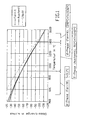
- Fig. 3 compares the calculated liquidus temperatures (black rectangles) according to Schwerdtfeger with the experimentally determined temperatures (line). At very high temperatures, the agreement is good, at low temperatures, the agreement decreases significantly. The calculated temperatures are above the experimental temperatures. Analog shows Fig. 4 the comparison of the calculated (black rectangles) with the experimental (line) determined liquidus temperatures according to Gibbs.
- the table lists the scopes of the Gibbs and Schwerdtfeger models. It becomes clear that the scope of the Gibbs model has a much wider range of analysis than the Schwerdtfeger model.
- the limits listed in the Thermocalc / Matcalc databases almost completely cover today's carbon and stainless steels produced worldwide. With these input data, the liquidus and solidus temperatures and the total enthalpy of a tested material can be determined with the greatest possible accuracy.
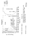
- FIG. 5 shows Gibbs' total enthalpy for a low carbon steel as a function of temperature. In addition, the figure shows the solidus and liquidus temperatures.
- the temperature distribution which is mediated with the Gibbs energies, is in FIG. 7 represented over the strand length.
- the temperatures in the center of the strand can be seen on the surface and in the core.
- the average temperature is shown from various thicknesses.
- the solidus and liquidus lines indicate where the strand is solidified. It can be seen that for this casting speed the strand center is solidified after about 23.6 m, which corresponds to the solidification length (position of the sump tip).
- FIG. 8 shows the temperature distribution of the isotherms in the strand.
- the bright color indicates the liquid core.
- the core is liquid up to the segments 8 - 10, after which the proportion of the solid phase increases.
- the solidification length is 23.6 m. The representation allows a quick overview of the liquid and solid phase in the cast strand.
- this value can then be used for the control and regulation of the hydraulic adjustment of the roller segments of a continuous casting plant for the implementation of a so-called "soft reduction".
- the casting method according to the invention characterized by the temperature calculation model, an optimal setting of the (roll) segments can be achieved and the internal quality improved. Investigations have shown that the internal quality of metal strands or slabs produced in this way in the most varied qualities of material is improved by the use of the method according to the invention.
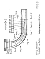
- FIG. 9 shows a schematic representation of a set up for the application of the casting method according to the invention and equipped with a computing device 1 or computing device, generally designated 2 continuous casting, wherein the computing device 1 is equipped with a formed as a metallurgical process model temperature calculation model that a DTR or DSC (Dynamic Temperature Control / Dynamic Solidification Control) regulation or based on it.
- the temperature calculation model can be used to calculate the temperature distribution prevailing inside a solidified material block or material section cast from liquid metal.
- the material block or material section is the cast strand 3 or metal strand consisting of metal.
- the cast strand 3 has a liquid sump 4, whose sump tip 5 defining the solidification length of the casting strand 3 is formed approximately in the considered in the casting direction end portion of the secondary cooling 6.
- the casting strand 3 six roller segments 7 or generally segments are formed to its deformation and support, which are provided with support rollers or strand guide rollers 8 and formed hydraulically adjustable.
- the strand guide rollers 8 run partly empty or are adjustable and formed rotationally driven.
- the continuous casting plant 2 has a distributor vessel 9 and a continuous casting mold 10 connected thereto. Molten steel flows from a ladle 11 into the distribution vessel 9 and from there into the mold 10. Below the mold 10 strand guide rollers 8 are formed for supporting the cast strand 3, which only has a very thin strand shell in this area.
- the cast strand 3 passes through a circular arc-shaped region and then runs out in a straightening zone and can then, for example, go through an immediately downstream roll stand 12.
- it is cooled in the region of the secondary cooling 6, for example by sprayed-on water or by a strand guide provided with an internal cooling.
- the supply of the cast strand with the desired amount of coolant, but also the setting of the casting speed is carried out via a closed or open loop 13 using the computer or computing device 1.
- the temperature distribution in the casting strand 3 and in particular the current position of the sump tip 5 is calculated in the manner explained above, namely online.
- the output variables obtained with this calculation process can also be processed in the arithmetic unit 1 and are then used in the context of the open or closed control and / or control circuit 13, the desired casting parameters, such as coolant inlet, casting speed, employment of the roll segments 7 or more set and situation-dependent to change.
- the desired casting parameters such as coolant inlet, casting speed, employment of the roll segments 7 or more set and situation-dependent to change.
- the metallurgical temperature calculation model imaging computer device 1 the occurrence of phases as described above in the way of detecting the respective Gibbs'schen energy is taken into account.
Description
Die Erfindung richtet sich auf ein Gießverfahren zur Herstellung eines aus flüssigem Metall gegossenen Materialblocks oder Materialabschnitts, bei welchem die im Innern des Materialblocks oder Materialabschnitts herrschende Temperaturverteilung mittels eines auf einer dynamischen Temperatur-Regelung (Dynamic Solidification Control) beruhenden Temperaturberechnungsmodells berechnet wird, wobei in einem Berechnungsschritt die Gesamtenthalpie des durch den Materialblock oder Materialabschnitt gebildeten Systems ermittelt sowie als eine Eingangsgröße in dem Temperaturberechnungsmodell verarbeitet wird und eine oder mehrere Ausgangsgröße(n) des Temperaturberechnungsmodells im Regelungs- und/oder Steuerungsprozess des Gießprozesses verwendet wird/werden.The invention is directed to a casting method for producing a liquid metal cast material block or material section, wherein the temperature distribution prevailing inside the material block or material section is calculated by means of a temperature calculation model based on a dynamic temperature control (Dynamic Solidification Control) Calculating step, the total enthalpy of the system formed by the material block or material portion is determined and processed as an input in the temperature calculation model and one or more output (s) of the temperature calculation model is used in the control and / or control process of the casting process.
Weiterhin richtet sich die Erfindung auf die Verwendung eines solchen Gießverfahrens.Furthermore, the invention is directed to the use of such a casting method.
Bei der Durchführung von Gießverfahren zur Herstellung von aus einem flüssigen Metall, insbesondere einem eisenhaltigen Material, gegossenen Materialblöcken oder Materialabschnitten kann es wichtig sein, die innere Temperaturverteilung und insbesondere den Bereich noch flüssigen Metalls und den Bereich schon erstarrten Metalls erkennen und lokalisieren zu können, insbesondere, um das Gießverfahren derart regeln und steuern zu können, dass ein optimales Erstarrungsprodukt erhalten wird. Insbesondere ist dies bei der Durchführung des Stranggießens von flüssigem Metall wichtig. So ist die Kenntnis der Temperaturverteilung für die ordnungsgemäße Durchführung des Stranggießverfahrens im Rahmen des Betriebes einer Stranggießanlage zum Erhalt eines qualitativ hochwertigen Produktes, wie einer Dünn- oder Dickbramme sowie von Knüppel- oder Langprodukten aus Stahl- und Eisenlegierungen von fundamentaler Bedeutung. Sollten im sich während des Stranggießens als Materialblock oder Materialabschnitt ausbildenden Metallstrang zu hohe Temperaturen eingestellt sein, führt dies während des Stranggießens des Materialstrangs zum Ausbauchen (bulging) des Strangs zwischen den Rollen. Stellen sich während des Stranggießens in dem Metallstrang zu niedrige Temperaturen ein, kann es während des Biegens und Richtens zu Fehlererscheinungen auf der Oberfläche von aus dem Metallstrang hergestellten Brammen kommen, die zu Rissen in der Bramme führen können. Die Temperaturverteilung bei einem Gießprozess, insbesondere Stranggießprozess, wird z. B. durch hohe Gießtemperaturen und hohe Gießgeschwindigkeiten beeinflusst. Werden diese Parameter größer, so nimmt auch die Erstarrungslänge zu, d. h. die Lage der Sumpfspitze im Metallstrang verschiebt sich in Gießrichtung mehr zum Ende des Metallstranges hin. Hierbei wird die maximal an einer Stranggießanlage mögliche Gießgeschwindigkeit durch die Erstarrungslänge begrenzt, da diese kleiner als die Maschinenlänge, d. h. die Stranggießanlagenlänge, sein muss. Sehr geringe Gießgeschwindigkeiten führen demgegenüber zu geringeren Temperaturen des Metallstranges bzw. der Bramme am Ende des eigentlichen Stranggießbereiches. Da hier aber häufig unmittelbar Öfen zur Behandlung der erhaltenen Bramme nachgeschaltet sind, die im Rahmen eines kontinuierlichen Stranggießprozesses von den Brammen durchlaufen werden, zum Beispiel bei sogenannten CSP (Compact Strip Production)-Anlagen, dürfen die Gießgeschwindigkeiten nicht zu gering sein, da anderenfalls die Ofeneinlauftemperaturen zu niedrig sind und bei Unterschreiten der Ofeneinlauftemperatur ggf. gewünschte Gefügeumwandlungen nicht in der gewünschten Qualität durchgeführt werden oder aber entsprechend erhöhte Energie zur Wiederaufheizung der Brammen im Ofenberreich bereitgestellt werden muss.When carrying out casting processes for producing material blocks or material sections cast from a liquid metal, in particular a ferrous material, it may be important to be able to recognize and localize the internal temperature distribution and in particular the area of still liquid metal and the area of already solidified metal, in particular in order to be able to control and control the casting process in such a way that an optimum solidification product is obtained. In particular, this is important in carrying out the continuous casting of liquid metal. Thus, knowledge of the temperature distribution is essential for the proper implementation of the continuous casting process in the operation of a continuous casting plant to obtain a high quality product such as a thin or thick slab, billet or long products of steel and iron alloys. Should be during the continuous casting as Set material block or material portion forming metal strand to high temperatures, this leads during the continuous casting of the material strand bulging of the strand between the rollers. If temperatures are too low during continuous casting in the metal strand, faults on the surface of slabs produced from the metal strand may occur during bending and straightening, which may lead to cracks in the slab. The temperature distribution in a casting process, in particular continuous casting process is z. B. influenced by high casting temperatures and high casting speeds. If these parameters increase, so does the solidification length, ie the position of the sump tip in the metal strand shifts more towards the end of the metal strand in the casting direction. In this case, the maximum possible casting speed at a continuous casting plant is limited by the solidification length, since this must be smaller than the machine length, ie the continuous casting plant length. In contrast, very low casting speeds lead to lower temperatures of the metal strand or the slab at the end of the actual continuous casting area. Since here, however, often directly furnaces for treating the resulting slab are followed, which are passed through in a continuous casting process of the slabs, for example in so-called CSP (Compact Strip Production) systems, the casting speeds must not be too low, otherwise the Furnace inlet temperatures are too low and falls below the kiln inlet temperature possibly desired microstructures conversions are not performed in the desired quality or correspondingly increased energy must be provided for reheating the slabs in Ofenberreich.
Die Temperaturverteilung und die Erstarrungslänge des Metallstranges oder einer Bramme sind daher insbesondere für die Steuerung des Gießverfahrens oder Gießprozesses sehr wichtige (Mess-)Größen oder Parameter, die aber nicht unmittelbar an jeder Stelle einer Stranggießanlage bestimmt oder ermittelt werden können. Pyrometer stehen zum Beispiel an einer Stranggießanlage in der Regel lediglich hinter der sogenannten Sekundärkühlzone und vor einer üblicherweise vorhandenen Schere zur Verfügung. Damit können die Temperaturen und damit auch die Temperaturverteilung in einer Bramme oder in dem gegossenen Metallstrang an der Oberfläche gemessen werden. Wichtig für die Steuerung insbesondere eines Stranggießverfahrens ist aber die Kenntnis der Temperaturverteilung in der Sekundärkühlzone. Hier können aufgrund des durch Besprühen der Oberfläche des Metallstranges mit Wasser auftretenden Spritzwassers die Temperaturen mittels eines Pyrometers kaum gemessen werden. Die Temperaturen im Inneren eines Metallstranges oder einer Bramme können ferner mit einem Pyrometer grundsätzlich nicht gemessen werden, so dass eine Temperaturverteilung im Inneren eines Materialblocks oder eines Metallstranges nur mittels eines Temperaturberechnungsmodells ermittelt werden kann. Ebenso ist die Lage der Sumpfspitze innerhalb des beim Stranggießen entstehenden Metallstranges nur mittels eines Temperaturberechnungsmodelles ermittelbar. Aufgrund des flüssigen Kerns in der Strangmitte im Bereich der Sumpfspitze ist die Ermittlung deren Lage mittels eines direkten Messverfahrens nicht möglich.The temperature distribution and the solidification length of the metal strand or a slab are therefore very important (measurement) variables or parameters, in particular for the control of the casting process or casting process, but which are not determined or determined directly at each point of a continuous casting plant can. Pyrometers, for example, are usually available at a continuous casting plant only behind the so-called secondary cooling zone and before a scissors usually present. Thus, the temperatures and thus the temperature distribution in a slab or in the cast metal strand can be measured on the surface. Important for the control, in particular a continuous casting but is the knowledge of the temperature distribution in the secondary cooling zone. Here, due to the spray water occurring by spraying the surface of the metal strand, the temperatures can hardly be measured by means of a pyrometer. Furthermore, the temperatures inside a metal strand or a slab can generally not be measured with a pyrometer, so that a temperature distribution in the interior of a material block or a metal strand can only be determined by means of a temperature calculation model. Likewise, the position of the sump tip within the metal strand formed during continuous casting can only be determined by means of a temperature calculation model. Due to the liquid core in the strand center in the area of the sump tip, it is not possible to determine its position by means of a direct measuring method.
Ein solches Temperaturberechnungsmodell stellt das sogenannte dynamische Temperatur-Regelungs-Modell oder DSC(Dynamic Solidification Control)-Modell/Programm dar. Mittels dieses Modells lassen sich die Temperaturverteilung, die Schalendicke und die Erstarrungslänge (Lage der Sumpfspitze) abhängig von den Prozessbedingungen in der jeweiligen Stranggießanlage bestimmen. Zusätzlich ist dieses Modell oder Programm für Regelungszwecke in der Sekundärkühlwasserzone einer Stranggießanlage einsetzbar. Als Regelungsgrößen können die Oberflächentemperatur des Metallstranges oder die Erstarrungslänge (Lage der Sumpfspitze) im Metallstrang Verwendung finden. Bei Vorgabe dieser Größen als Setzwerte berechnet das Modell/Programm die zur Erreichung dieser Werte/Parameter in der Sekundärkühlzone benötigten Wassermengen. Die Ergebnisse werden unmittelbar visualisiert und bei jeder neuen zyklischen Berechnung aktualisiert. In diesem Sinne liegt eine online-Berechnung und -Steuerung vor.Such a temperature calculation model represents the so-called dynamic temperature control model or DSC (Dynamic Solidification Control) model / program. By means of this model, the temperature distribution, the shell thickness and the solidification length (position of the sump tip) depending on the process conditions in the respective Determine continuous casting plant. In addition, this model or program can be used for control purposes in the secondary cooling water zone of a continuous casting plant. As control variables, the surface temperature of the metal strand or the solidification length (position of the sump tip) can be used in the metal strand. Given these values as set values, the model / program calculates the amounts of water needed to achieve these values / parameters in the secondary cooling zone. The results will be immediately visualized and updated with each new cyclic calculation. In this sense, there is an online calculation and control.
Die Strangtemperatur und die Erstarrungslänge werden bei diesem DSC-Modell/Programm auf Basis der Fourier'schen Wärmegleichung berechnet. Eine notwendige Eingangsgröße in diese Wärmegleichung ist die Gesamtenthalpie des Systems. Die Enthalpie ist jedoch nicht messbar und für bestimmte Metallzusammensetzungen, insbesondere Eisen- oder Stahllegierungen, nur ungenau mittels Näherungsgleichungen zu beschreiben.The strand temperature and the solidification length are calculated on this DSC model / program based on the Fourier heat equation. A necessary input into this heat equation is the total enthalpy of the system. However, the enthalpy can not be measured and for certain metal compositions, in particular iron or steel alloys, only vaguely described by means of approximate equations.
Zum Beispiel gibt Schwerdtfeger als Herausgeber in seinem Buch "Metallurgie des Stranggießens", Verlag Stahleisen mbH, 1992 empirische Regressionsgleichungen für die Enthalpie von unlegierten Kohlenstoffstählen an, die innerhalb bestimmter, enger Analysegrenzen mit brauchbarer Genauigkeit verwendet werden können. Diese Regressionsgleichungen sind allerdings Näherungsgleichungen und haben keine physikalische Grundlage. Richter in "Die wichtigsten physikalischen Eigenschaften von 52 Eisenwerkstoffen", Verlag Stahleisen Düsseldorf, 1973 gibt für Reineisen eine genaue thermodynamische Beziehung für die Enthalpie der einzelnen Phasen an. Reineisen hat jedoch keine technische Bedeutung. Für Stahlwerkstoffe liegt für die Gesamtenthalpie eines Systems keine exakte thermodynamische Angabe vor.For example, Schwerdtfeger as publisher in his book "Metallurgie des Stranggießens", Verlag Stahleisen mbH, 1992 gives empirical regression equations for the enthalpy of carbon steels, which can be used within certain narrow analysis limits with reasonable accuracy. However, these regression equations are approximate equations and have no physical basis. Richter in "The Most Important Physical Properties of 52 Ferrous Materials", Verlag Stahleisen Düsseldorf, 1973 gives a precise thermodynamic relationship for pure iron for the enthalpy of the individual phases. However, pure iron has no technical significance. For steel materials there is no exact thermodynamic data for the total enthalpy of a system.
Dies führt dazu, dass die numerische Lösung der Fourier'schen Wärmegleichung ungenaue, zumindest hinsichtlich ihrer Genauigkeit verbesserungsfähige Temperaturergebnisse und damit eine entsprechend ungenaue bzw. hinsichtlich ihrer Genauigkeit verbesserungsfähige Bestimmung der Lage der Sumpfspitze (Erstarrungslänge) hervorbringt. Der Nachteil dieses Standes der Technik besteht also darin, dass die Lösung der Fourier'schen Wärmegleichung mit numerischen Verfahren durchgeführt wird, die in Abhängigkeit von der Qualität der Eingangsdaten ein Temperaturergebnis, das heißt eine Temperaturverteilung im Metallstrang liefern, so dass das erhaltene Ergebnis bei fehlerhaften oder ungenauen Enthalpie-Eingangsdaten zu Abweichungen zwischen der berechneten Temperaturverteilung oder Temperatur und der jeweils real existierenden, ggf. durch Messungen belegten, Temperaturverteilung führt. Zudem wird bei der Eingabe ungenauer Enthalpiewerte die Lage der Liquidus- und Solidus-Temperaturen nicht zutreffend ermittelt, so dass auch die Erstarrungslänge bzw. die Lage der Sumpfspitze nicht der Realität entsprechend berechnet wird. Hierdurch kann es insbesondere dann, wenn bei einem Stranggießverfahren eine sogenannte soft reduction, also eine Verformung des Metallstranges durch Anstellung von Rollensegmenten, vorgenommen wird, zu unzutreffenden Anstellungen der Rollensegmente kommen, so dass in Folge davon die durch die Softreduktion erwünschte Qualitätsverbesserung des Brammenmaterials nicht erreicht wird.The result of this is that the numerical solution of the Fourier thermal equation produces inaccurate temperature results that can be improved, at least with regard to their accuracy, and thus a correspondingly inaccurate determination of the position of the sump tip (solidification length) which can be improved in terms of its accuracy. The disadvantage of this prior art is therefore that the solution of the Fourier heat equation is performed by numerical methods which, depending on the quality of the input data, provide a temperature result, that is to say a temperature distribution in the metal strand, so that the result obtained is faulty or Inaccurate enthalpy input data to deviations between the calculated temperature distribution or temperature and the actual existing, possibly occupied by measurements, temperature distribution leads. In addition, the position of the liquidus and solidus temperatures is not correctly determined when entering inaccurate enthalpy values, so that the solidification length or the position of the sump tip is not calculated in accordance with reality. As a result, in particular when a so-called soft reduction, that is to say a deformation of the metal strand by setting roll segments, is carried out, incorrect positioning of the roll segments may occur, so that as a result the quality improvement of the slab material desired by the soft reduction does not reach becomes.
Ein gattungsgemäßes Verfahren ist aus der
Die
Die Berücksichtigung einer Summenformel der Gesamtenthalpie ist ferner aus der
Der Erfindung liegt daher die Aufgabe zugrunde, eine Lösung zu schaffen, die eine verbesserte Berechnung und Vorhersage der Temperaturverteilung in einem aus flüssigem Metall gegossenen Materialabschnitt oder Materialblock während des Erstarrungsvorganges ermöglicht und insbesondere bei einem Stranggießverfahren oder -prozess eine verbesserte Berechnung oder Vorhersage der Erstarrungslänge (Lage der Sumpfspitze) in dem erstarrenden Metallstrang ermöglicht.It is therefore an object of the invention to provide a solution which enables an improved calculation and prediction of the temperature distribution in a liquid metal cast piece or block of material during the solidification process, and in particular in a continuous casting process or process, an improved calculation or prediction of the solidification length (FIG. Position of the sump tip) in the solidifying metal strand allows.
Bei einem Gießverfahren der eingangs näher bezeichneten Art wird diese Aufgabe erfindungsgemäß dadurch gelöst, dass die Gesamtenthalpie aus der Summe der freien molaren Enthalpien (Gibbs'schen Energien) aller im Materialblock oder Materialabschnitt aktuell vorhandenen Phasen und/oder Phasenanteile berechnet wird.In a casting method of the kind described in more detail, this object is achieved according to the invention by calculating the total enthalpy from the sum of the free molar enthalpies (Gibbs energies) of all phases and / or phase portions currently present in the material block or material section.
Ebenso wird diese Aufgabe gelöst durch die Verwendung eines solchen Gießverfahrens beim Stranggießen von metallischem Werkstoff in einer Stranggießanlage zur Vorhersage und Kontrolle der Temperaturverteilung sowie zur Ermittlung der Lage der Sumpfspitze oder der Erstarrungslänge in einem gegossenen Gießstrang.Likewise, this object is achieved by the use of such a casting process in the continuous casting of metallic material in a continuous casting plant for the prediction and control of the temperature distribution and for determining the position of the sump tip or the solidification length in a cast casting strand.
Zweckmäßige Ausgestaltungen und vorteilhafte Weiterbildungen sind Gegenstand der jeweils abhängigen Unteransprüche.Advantageous embodiments and advantageous developments are the subject of the respective dependent claims.
Die Erfindung geht von der Erkenntnis aus, dass sich die Temperaturverteilung und damit auch die Lage der Sumpfspitze im erstarrenden Metallstrang oder im erstarrenden Materialblock bei einem Gießverfahren, insbesondere Stranggießverfahren, dadurch verbessern lässt, dass die Gesamtenthalpie aus der Summe der freien molaren Enthalpien (Gibbs'schen Energien) aller im Materialblock oder Materialabschnitt oder Teilstrang aktuell vorhandenen Phasen und/oder Phasenanteile berechnet wird. Hierdurch lässt sich die für die Berechnung weiterer Größen in dem Temperaturberechnungsmodell notwendige Gesamtenthalpie genauer als bei dem aus der Praxis bekannten Temperaturberechnungsmodell berechnen, so dass die Solidus- und LiquidusTemperatur und folglich insgesamt die Berechnung der Temperaturverteilung und die Ermittlung bzw. Berechnung der Erstarrungslänge mit höherer und größerer Genauigkeit erfolgt. Daraus ergibt sich eine besser mit der Realität übereinstimmende Berechnung der Temperaturverteilung in der Sekundärkühlzone einer Stranggießanlage sowie der Position der Lage der Sumpfspitze (Erstarrungslänge). Insbesondere lässt sich damit die Temperaturverteilung im erstarrenden Metallstrang einer Stranggießanlage berechnen, so dass sich mittels des genutzten Temperaturberechnungsmodells eine gewünschte/vorgegebene, werkstoffabhängige, optimale Temperaturkurve im erstarrenden Metallstrang eingestellt und kontrolliert werden kann. Da die Gesamtenthalpie als Eingangsgröße für die Temperaturberechnung für nahezu alle heute weltweit hergestellten Werkstoffe mit Hilfe der Gibbs-Energien (freie molare Energie) bestimmt oder berechnet werden kann, wird die Temperaturberechnung mit größtmöglicher Sicherheit der Eingangsdaten durchgeführt. Ein weiterer Vorteil der Erfindung besteht auch in der nun hinsichtlich der Genauigkeit verbesserten Berechnung der Erstarrungslänge und damit verbesserten Übereinstimmung mit der Realität der Lage der Sumpfspitze im erstarrenden Metallstrang einer Stranggießanlage. Mittels der Gibbs-Energien können die Liquidus- und Solidus-Temperaturen genauer als mit den bisher verwendeten empirischen Formeln berechnet werden. Zusammen mit der Temperaturberechnung wird auf diesem Wege die Erstarrungslänge mit verbesserter Genauigkeit ermittelt. Damit lässt sich beim Betrieb einer Stranggießanlage sicherstellen, dass die Erstarrungslänge immer kleiner als die Anlagenlänge ist. Weiterhin können die durch das Temperaturberechnungsmodell ermittelten Ausgangsgrößen dazu benutzt werden, die hydraulische Anstellung der Anstellsegmente, zum Beispiel zur Durchführung einer sogenannten soft reduction, zu verwenden, wobei aufgrund der nun genauer bekannten Erstarrungslänge die Anstellung von Rollensegmenten genauer und optimaler erfolgen kann, was zu einer Qualitätsverbesserung der hergestellten Brammen führt. Das Dynamic Solidification Control (DSC)-Temperaturberechnungsmodell kommt insbesondere beim Stranggießen und hier beim sogenannten CSP (Compact Strip Production)-Prozess zum Einsatz und ist Teil der Automation. Mit der "dynamischen Erstarrungsregelung" werden die Brammen gezielt heruntergekühlt, um bestimmte metallurgische Eigenschaften der Werkstoffe zu erhalten. Dazu sind in dem Automationsrechner bzw. der Rechner- oder Recheneinrichtung entsprechend den Stahlgüten und den Brammenabmessungen vordefinierte Kühlmodelle hinterlegt, mit denen die Kühleinrichtungen insbesondere der Sekundärkühlzone einer Strang- oder eine CSP-Anlage gesteuert werden. Im Rahmen einer sogenannten soft reduction kommt dabei beim Stranggießen eine hydraulische Segmentanstellung zum Einsatz, welche durch eine dynamic soft reduction-Technologie gesteuert wird. Hierbei üben die Richt- und Treibrollen mittels ihrer Hydraulik in den Segmenten einen gezielten Druck auf die Brammen im Bereich der Enderstarrung aus. Dadurch werden Kernseigerungen im Inneren der Bramme minimiert bzw. Kernporositäten unterdrückt. Auf diese Weise lassen sich hochqualitative Stähle produzieren und die Gießanlage erhält eine hohe Variabilität hinsichtlich des Stahlgütenspektrums. Konkret dargestellt ist der Berechnungsschritt zur Ermittlung der Gesamtenthalpie in Ausgestaltung der Erfindung dadurch, dass im Rahmen des Temperaturberechnungsmodells die Gesamtenthalpie als freie molare Gesamtenthalpie (H) des Systems mittels der Gibbs-Energie (G) bei konstantem Druck (p) nach der Gleichung ![]()
ermittelt wird, wobei H = die molare Enthalpie des Systems, G = die Gibbs-Energie des Systems, T = die absolute Temperatur in Kelvin und p = den Druck des Systems bedeuten.The invention is based on the recognition that the temperature distribution and thus also the position of the sump tip in the solidifying metal strand or in the solidifying material block in a casting process, in particular continuous casting, can be improved by the total enthalpy from the sum of the free molar enthalpies (Gibbs' energies) of all in the material block or material section or sub-strand currently existing phases and / or phase components is calculated. As a result, the total enthalpy necessary for the calculation of further variables in the temperature calculation model can be calculated more accurately than in the temperature calculation model known from practice, so that the solidus and liquidus temperature and consequently the calculation of the temperature distribution and the determination or calculation of the solidification length with higher and greater accuracy. This results in a better coinciding with the reality calculation of the temperature distribution in the secondary cooling zone of a continuous casting plant and the position of the position of the sump tip (solidification length). In particular, this can be used to calculate the temperature distribution in the solidifying metal strand of a continuous casting plant, so that a desired / predetermined, material-dependent, optimum temperature curve can be set and controlled in the solidifying metal strand by means of the temperature calculation model used. Since the total enthalpy can be determined or calculated as the input quantity for the temperature calculation for almost all materials produced worldwide today with the aid of Gibbs energies (free molar energy), the temperature calculation is carried out with the greatest possible reliability of the input data. Another advantage of the invention is also in the now in terms of accuracy improved calculation of the solidification length and thus improved compliance with the reality of the position of the sump tip in the solidifying metal strand of a continuous casting. Using the Gibbs energies, the liquidus and solidus temperatures can be calculated more accurately than with the previously used empirical formulas. Together with the temperature calculation, the solidification length is determined with improved accuracy in this way. Thus, when operating a continuous casting plant, it can be ensured that the solidification length is always smaller than the plant length. Furthermore, the determined by the temperature calculation model outputs can be used to use the hydraulic adjustment of Anstellsegmente, for example, to perform a so-called soft reduction, due to the now more accurate solidification length employment of roller segments can be made more accurate and optimal, resulting in a Quality improvement of the produced slabs leads. The Dynamic Solidification Control (DSC) temperature calculation model is used in particular in continuous casting and here in the so-called CSP (Compact Strip Production) process and is part of the automation. With the "dynamic solidification control" the slabs are specifically cooled down in order to obtain certain metallurgical properties of the materials. For this purpose, predefined cooling models are stored in the automation computer or the computer or computing device in accordance with the steel grades and the slab dimensions with which the cooling devices, in particular the secondary cooling zone of a strand or a CSP plant, are controlled. Within the framework of a so-called soft reduction, continuous segmental casting is used for hydraulic segment adjustment, which is controlled by a dynamic soft reduction technology. Here, the straightening and driving rollers exert a targeted pressure on the slabs in the area of the final solidification by means of their hydraulics in the segments. This minimizes core segregations inside the slab and suppresses core porosity. In this way, high-quality steels can be produced and the casting plant receives a high variability with regard to the steel grade spectrum. Specifically, the calculation step for determining the total enthalpy in embodiment of the invention is characterized in that in the temperature calculation model, the total enthalpy as the total free enthalpy (H) of the system by means of the Gibbs energy (G) at constant pressure (p) according to the equation ![]()
where H = the molar enthalpy of the system, G = the Gibbs energy of the system, T = the absolute temperature in Kelvin and p = the pressure of the system.
Bestandteil der Ausgestaltung des erfindungsgemäßen Gießverfahrens ist weiterhin, dass im Rahmen des Temperaturberechnungsmodells die Temperaturverteilung mittels der Fourier'schen Wärmegleichung ![]()
ermittelt wird, wobei ρ = die Dichte, cp = die spezifische Wärmekapazität bei konstantem Druck, T = die berechnete absolute Temperatur in Kelvin, λ = die Wärmeleitfähigkeit, s = die zugehörige Ortskoordinate, t = die Zeit und Q = die während der Phasenumwandlung flüssig - fest frei werdende Energie des Systems bedeuten.Part of the embodiment of the casting method according to the invention is further that, in the context of the temperature calculation model, the temperature distribution by means of the Fourier heat equation ![]()
where ρ = the density, c p = the specific heat capacity at constant pressure, T = the calculated absolute temperature in Kelvin, λ = the thermal conductivity, s = the associated spatial coordinate, t = the time and Q = the during the phase transformation liquid - mean fixed energy of the system.
In dem Temperaturberechnungsmodell wird weiterhin die während der Phasenumwandlung von flüssig nach fest frei werdende Energie mittels der Gleichung ![]()
ermittelt, wobei Q = die frei werdende Energie während der Phasenumwandlung, ρ = die Dichte, L = die latente Schmelzwärme, t = die Zeit und fs = den Phasenumwandlungsgrad des Systems bedeuten, was die Erfindung ebenfalls vorsieht.In the temperature calculation model, furthermore, the energy released during the phase transformation from liquid to solid is determined by means of the equation ![]()
where Q = the energy released during the phase transformation, ρ = the density, L = the latent heat of fusion, t = the time and f s = the phase transformation degree of the system, which the invention also provides.
Ferner ist in Ausgestaltung der Erfindung vorgesehen, dass im Rahmen des Temperaturberechnungsmodells für eine Phasenmischung die Gibbs-Energie (G) des Gesamtsystems als Summe der die Gibbs-Energien der Reinphasen sowie deren Phasenanteilen nach der Gleichung ![]()
ermittelt wird, wobei G = die Gibbs-Energie des Systems, fi = der Gibbs-Energieanteil der jeweiligen Phase oder des jeweiligen Phasenanteils am Gesamtsystem und Gi = die Gibbs-Energie der jeweiligen Reinphase oder des jeweiligen Phasenanteils des Systems bedeuten.Furthermore, it is provided in an embodiment of the invention that, as part of the temperature calculation model for a phase mixture, the Gibbs energy (G) of the total system as the sum of the Gibbs energies of the pure phases and their phase components according to the equation ![]()
where G = the Gibbs energy of the system, f i = the Gibbs energy portion of the respective phase or of the respective phase portion of the overall system, and G i = the Gibbs energy of the respective pure phase or the respective phase portion of the system.
Die Gibbs-Energien lassen sich in vorteilhafter Weise gemäß Weiterbildung der Erfindung dadurch ermitteln, dass das im Rahmen des Temperaturberechnungsmodells für ein System mit Anteilen an Austenit-, Ferrit- und Flüssigphase die Gibbs-Energie nach folgender Gleichung 
ermittelt wird, wobei GΦ = die Gibbs-Energie einer jeweiligen Phase Φ, xi Φ = der Molenbruch der i-ten Komponente der jeweiligen Phase Φ, Gi Φ = die Gibbs-Energie der i-ten Komponente der jeweiligen Phase Φ, R = die allgemeine Gaskonstante, T = die absolute Temperatur in Kelvin, EGΦ = die Gibbs-Energie für eine nicht ideale Mischung und magnGΦ = die magentische Energie des Systems bedeuten.The Gibbs energies can be determined in an advantageous manner according to a further development of the invention, that in the context of the temperature calculation model for a system with portions of austenite, ferrite and liquid phase, the Gibbs energy according to the following equation
where G Φ = the Gibbs energy of a respective phase Φ, x i Φ = the mole fraction of the ith component of the respective phase Φ, G i Φ = the Gibbs energy of the ith component of the respective phase Φ, R = the general gas constant, T = the absolute temperature in Kelvin, E G Φ = the Gibbs energy for a non-ideal mixture and magn G Φ = the magenta energy of the system.
Weiterhin wird in Ausgestaltung der Erfindung zweckmäßigerweise berücksichtigt, dass im Rahmen des Temperaturberechnungsmodells die Gibbs-Energie für eine nicht ideale Mischung (EGΦ) nach der Gleichung ![]()
ermittelt wird, wobei EGΦ = die Gibbs-Energie für eine nicht ideale Mischung, xi = den Molenbruch der i-ten Komponente, xj = den Molenbruch der j-ten Komponente, xk = den Molenbruch der k-ten Komponente, a = einen Korrekturterm, aLΦ i,j = Wechselwirkungsparameter verschiedener Ordnung und aLΦ i,j,k = aLΦ i,j = Wechselwirkungsparameter verschiedener Ordnung des Gesamtsystems bedeuten.Furthermore, in an embodiment of the invention, it is expediently taken into consideration that in the context of the temperature calculation model the Gibbs energy for a non-ideal mixture ( E G Φ ) is calculated according to the equation ![]()
where E G Φ = the Gibbs energy for a non-ideal mixture, x i = the mole fraction of the i-th component, x j = the mole fraction of the j-th component, x k = the mole fraction of the k-th component , a = a correction term, a L Φ i, j = interaction parameters of different order and a L Φ i, j, k = a L Φ i, j = mean interaction parameters of different order of the total system.
Ebenso wird in dem Temperaturberechnungsmodell beim Gießverfahren in Ausgestaltung der Erfindung zweckmäßigerweise berücksichtigt, dass im Rahmen des Temperaturberechnungsmodells, der Anteil der magnetischen Energie (magnGΦ) nach der Gleichung ![]()
ermittelt wird, wobei magnGΦ = die magnetische Energie, R = die allgemeine Gaskonstante, T = die absolute Temperatur in Kelvin, β = das magnetische Moment und f(τ) = den Anteil am Gesamtsystem in Abhängigkeit von der normierten Curietemperatur (τ) des Gesamtsystems bedeuten.Likewise, it is expediently taken into account in the temperature calculation model in the casting method in an embodiment of the invention that in the context of the temperature calculation model , the proportion of the magnetic energy ( magn G Φ ) according to the equation ![]()
where magn G Φ = the magnetic energy, R = the general gas constant, T = the absolute temperature in Kelvin, β = the magnetic moment and f (τ) = the proportion of the total system as a function of the normalized Curie temperature (τ) mean the entire system.
Insbesondere ist das erfindungsgemäße Verfahren beim Stranggießen mit Vorteil anzuwenden, so dass die Erfindung sich weiterhin dadurch auszeichnet, dass ein Stranggussstrang gegossen wird, wobei mittels des Temperaturberechnungsmodells als Ausgangsgröße (n) die Lage der Sumpfspitze und/oder die Temperaturverteilung in dem den Stranggussstrang ausbildenden Materialblock oder Materialabschnitt ermittelt wird.In particular, the method according to the invention is advantageously used in continuous casting, so that the invention is further characterized in that a continuous casting is cast, wherein by means of the temperature calculation model as output variable (s) the position of the sump tip and / or the temperature distribution in the material block forming the continuous casting strand or material section is determined.
Ebenso sieht die Erfindung daher in Weiterbildung vor, dass es als Bestandteil eines Steuerungs- und/oder Regelungsverfahrens beim Stranggießen von Metall, insbesondere eisenhaltigem Metall, vorzugsweise Stahl, ausgeführt wird.Likewise, the invention therefore provides in a further development that it is as part of a control and / or regulation method in the continuous casting of metal, in particular iron-containing metal, preferably steel, executed.
Mit dem erfindungsgemäßen Verfahren lässt sich in vorteilhafter Weise auch eine sogenannte soft reduction durchführen. Die Erfindung sieht daher weiterhin vor, dass anhand der Lage der Sumpfspitze die Erstarrungslänge eines Stranggussstranges ermittelt und die Erstarrungslänge als eine Eingangsgröße der Steuerung und/oder Regelung der hydraulischen Anstellung der Segmente der Stranggussanlage längs des Stranggussstranges zugeführt wird.With the method according to the invention can be carried out in an advantageous manner, a so-called soft reduction. The invention therefore further provides that, based on the position of the sump tip, the solidification length of a continuous casting strand is determined and the solidification length is supplied as an input variable to the control and / or regulation of the hydraulic adjustment of the segments of the continuous casting plant along the continuous casting strand.
Zudem lässt sich mit der Erfindung auch die Sekundärkühlung einer Stranggießanlage steuern, so dass sich das erfindungsgemäße Verfahren weiterhin dadurch auszeichnet, dass mittels des als metallurgisches Prozessmodell ausgebildeten Temperaturberechnungsmodell die Sekundärkühlung einer Stranggießanlage gesteuert wird.In addition, the invention can also control the secondary cooling of a continuous casting plant, so that the method according to the invention is further distinguished by the fact that the secondary cooling of a continuous casting plant is controlled by means of the temperature calculation model designed as a metallurgical process model.
Da die Gibbs-Energien für nahezu alle heute weltweit hergestellten Werkstoffe bereit stehen, kann der Temperaturverlauf im Materialblock werkstoffabhängig ermittelt werden. Die Erfindung sieht daher weiterhin vor, dass mittels des Temperaturberechnungsmodells der Temperaturverlauf im Materialblock oder Materialabschnitt werkstoffabhängig ermittelt und eingestellt wird.Since the Gibbs energies are available for almost all materials produced worldwide today, the temperature profile in the material block can be determined depending on the material. The invention therefore further provides that the temperature profile in the material block or material section is determined and set as a function of the material by means of the temperature calculation model.
Da sich mit dem erfindungsgemäßen Verfahren sehr schnell und zeitnah die Temperaturverteilung in einem Materialblock oder -abschnitt, insbesondere dem sich beim Stranggießen ausbildenden erstarrenden Metallstrang berechnen lässt, eignet sich die Verwendung des Verfahrens bzw. der Berechnungsmethode insbesondere dazu, diese Online durchzuführen und zur Steuerung des Stranggießprozesses oder -verfahrens zu benutzen. Die Verwendung zeichnet sich in Ausgestaltung daher weiterhin dadurch aus, dass das Gießverfahren und damit das diesem zugrunde liegende Temperaturberechnungsmodell zur Online-Ermittlung der Temperaturverteilung und der Lage der Sumpfspitze sowie zur Steuerung des Stranggießprozesses verwendet wird.Since the method according to the invention allows the temperature distribution in a material block or section, in particular the solidifying metal strand forming during continuous casting, to be calculated very quickly and promptly, the method or the method of calculation is particularly suitable for performing this online and for controlling the Continuous casting process or method to use. The use records Therefore, in an embodiment, it continues to be characterized by the fact that the casting method and thus the temperature calculation model on which it is based are used for online determination of the temperature distribution and the position of the sump tip and for controlling the continuous casting process.
Von Vorteil ist die Verwendung des Gießverfahrens auch bei der Durchführung eines Soft Reduction-Prozesses beim Stranggießen, was die Erfindung ebenfalls vorsieht. Bei der Durchführung eines Soft Reduction-Prozesses werden die Rollensegmente der Stranggießanlage hydraulisch gegen den sich bildenden Metallstrang angestellt, um Fehlerbildungen im Inneren des Metallstranges beim Erstarren insbesondere im Bereich der Sumpfspitze zu vermeiden.The use of the casting method is also advantageous when carrying out a soft reduction process during continuous casting, which the invention also provides. When performing a soft reduction process, the roll segments of the continuous casting machine are hydraulically turned against the forming metal strand to avoid formation of defects in the interior of the metal strand during solidification, especially in the area of the sump tip.
Schließlich zeichnet sich die Erfindung dadurch aus, dass die Verwendung des Gießverfahrens zur Erhöhung der Prozessstabilität und Produktverbesserung beim Stranggießen erfolgt.Finally, the invention is characterized by the fact that the use of the casting process for increasing the process stability and product improvement during continuous casting takes place.
Die Erfindung ist nachstehend näher erläutert, wobei verschiedene Figuren zur Verständniserleichterung beigefügt sind. Von diesen zeigen
Figur 1- eine Darstellung der Gibbs-Energie für Reineisen,
Figur 2- ein (konstruiertes) Phasendiagramm mit Gibbs-Energien,
Figur 3- einen Vergleich berechneter und experimenteller LiquidusTemperaturen nach Schwerdtfeger,
Figur 4- einen Vergleich berechneter und experimenteller LiquidusTemperaturen nach Gibbs,
Figur 5- den Verlauf der Gesamtenthalpie nach Gibbs für einen kohlenstoffarmen Stahl,
Figur 6- den Verlauf der Phasenanteile nach Gibbs für einen kohlenstoffarmen Stahl,
Figur 7- die Temperaturverteilung über der Stranglänge errechnet auf Basis des erfindungsgemäßen Temperaturberechnungsmodells,
Figur 8- eine isothermische Darstellung der Temperaturverteilung berechnet nach dem erfindungsgemäßen Temperaturberechnungsmodell und in
Figur 9- in schematischer Darstellung eine zur Durchführung des erfindungsgemäßen Gießverfahrens eingerichtete Stranggießanlage
- FIG. 1
- a representation of Gibbs energy for pure iron,
- FIG. 2
- a (constructed) phase diagram with Gibbs energies,
- FIG. 3
- a comparison of calculated and experimental liquidus temperatures according to Schwerdtfeger,
- FIG. 4
- a comparison of calculated and experimental liquidus temperatures according to Gibbs,
- FIG. 5
- Gibbs' total enthalpy for a low-carbon steel,
- FIG. 6
- the course of Gibbs' phase shares for a low-carbon steel,
- FIG. 7
- the temperature distribution over the strand length is calculated on the basis of the temperature calculation model according to the invention,
- FIG. 8
- an isothermal representation of the temperature distribution calculated according to the temperature calculation model according to the invention and in
- FIG. 9
- in a schematic representation of an established for carrying out the casting method according to the invention continuous casting
Kern des beim erfindungsgemäßen Gießverfahrens zur Anwendung kommenden Temperaturberechnungsmodelles, dem DSC-Programm/Modell, ist die Berechnung der Strangtemperatur und der Erstarrungslänge (Lage der Sumpfspitze). Die Berechnung erfolgt über ein Finite-Differenzen-Verfahren. Der Materialblock oder Materialabschnitt, das heißt beim Stranggießen der entstehende Metallstrang, wird dabei in kleine Elemente unterteilt, so dass die Geometrie der Kokille, der Strangführung und die Abmessungen der Bramme berücksichtigt werden. Die Randbedingungen können mit den Abmessungen der Kühlzonen, der Wassermengen und der Temperatur des Kühlwassers und der Umgebungstemperatur formuliert werden. Während der Berechnung werden die Prozessgrößen wie Gießgeschwindigkeit und Gießtemperatur berücksichtigt und gehen bei einer Änderung sofort und unmittelbar in die Neuberechnung ein. Als Ergebnis ergeben sich eine Temperaturverteilung im Strang, eine dazu korrelierende entsprechende Schalendicke des Stranges und eine Erstarrungslänge im Strang.The core of the temperature calculation model used in the casting method according to the invention, the DSC program / model, is the calculation of the strand temperature and the solidification length (position of the sump tip). The calculation is made using a finite difference method. The material block or material section, that is to say in the case of continuous casting of the resulting metal strand, is subdivided into small elements, so that the geometry of the mold, the strand guide and the dimensions of the slab are taken into account. The boundary conditions can be formulated with the dimensions of the cooling zones, the quantities of water and the temperature of the cooling water and the ambient temperature. During the calculation, the process variables such as casting speed and casting temperature are taken into account and immediately and immediately enter the recalculation in case of a change. The result is a temperature distribution in the strand, a correlated corresponding shell thickness of the strand and a solidification length in the strand.
Basis der Temperaturberechnung ist die Fourier'sche Wärmegleichung (1), in der cp die spezifische Wärmekapazität des Systems, λ die Wärmeleitfähigkeit, p die Dichte und s die Ortskoordinate darstellen. T gibt die berechnete Temperatur an. Der Term Q auf der rechten Seite berücksichtigt freiwerdende Energien während der Phasenumwandlung (Gleichung 2). Beim Übergang von flüssig nach fest kennzeichnet dieser Term die Schmelzwärme, fs gibt den Phasenumwandlungsgrad an. 
![]()
![]()
Als notwendige Eingangsgrößen der Gleichung sind die Wärmeleitung und die Gesamtenthalpie besonders wichtig, da diese Größen das Temperaturergebnis maßgeblich beeinflussen. Die Wärmeleitfähigkeit ist eine Funktion der Temperatur, der chemischen Zusammensetzung und des Phasenanteils und kann experimentell genau ermittelt werden.As necessary input variables of the equation, the heat conduction and the total enthalpy are particularly important, since these variables significantly influence the temperature result. The thermal conductivity is a function of temperature, chemical composition and phase content and can be determined experimentally.
Der Gesamtenthalpie H oder die molare Enthalpie des durch einen beim Gießen erstarrenden Materialbereich oder Materialabschnitt oder Metallstrang gebildeten Systems kann über die Gibbs-Energie wie folgt (3) berechnet werden: 
mit der molaren Gibbs Energie G des Systems. Für eine Phasenmischung kann die Gibbs-Energie des Gesamtsystems über die Gibbs Energien der Reinphasen sowie deren Phasenanteilen berechnet werden ![]()
mit den Phasenanteilen f ϕ der Phase ϕ und G ϕ der molaren Gibbs Energie dieser Phase. Für die Austenit-, Ferrit- und Flüssigphase (ϕ) ergibt sich die Gibbs Energie zu 
![]()
![]()
with the molar Gibbs energy G of the system. For a phase mixture, the Gibbs energy of the total system can be calculated by the Gibbs energies of the pure phases and their phase proportions ![]()
with the phase fractions f φ of the phase φ and G φ of the molar Gibbs energy of this phase. For the austenite, ferrite and liquid phases (φ) the Gibbs energy is produced ![]()
![]()
In Gleichung (4) entsprechen die Terme jeweils einer Einzelelement-Energie, einem Beitrag für die ideale Mischung sowie einem Beitrag für die nicht ideale Mischung und der magnetischen Energie (Gleichung 7). Bei bekannter Gibbs-Energie des Systems kann daraus die molare spezifische Wärmekapazität berechnet werden: 
Die Parameter der Terme der Gleichungen (5) - (7) sind in einer Thermocalc- und Matcalc-Datenbank aufgeführt und können zur Ermittlung der Gibbs-Energien einer Stahlzusammensetzung verwendet werden. Mit Hilfe einer mathematischen Ableitung ergibt sich daraus die Gesamtenthalpie dieser Stahlzusammensetzung.The parameters of the terms of equations (5) - (7) are listed in a Thermocalc and Matcalc database and can be used to determine the Gibbs energies of a steel composition. With the help of a mathematical derivation, this results in the total enthalpy of this steel composition.
In
Für die Temperaturberechnung nach den Gleichungen (1)-(3) ist es zunächst notwendig, die Liquidus- und Solidus-Temperaturen zu ermitteln, die den Übergang der Schmelze zur festen Phase angeben.
Die Gültigkeitsbereiche des Gibbs- und des Schwerdtfeger-Modells in Bezug auf die Zusammensetzung einer Metalllegierung zeigt die nachstehende Tabelle:
- Schwerdtfeger: Grenzen gültig mit einer angegebenen Genauigkeit DT = 2°C
- Gibbs: Gültigkeitsbereich nach Thermocalc/Matcalc- Datenbanken
- Schwerdtfeger: limits valid with a specified accuracy DT = 2 ° C
- Gibbs: Scope for Thermocalc / Matcalc databases
In der Tabelle sind die Gültigkeitsbereiche des Gibbs- und des Schwerdtfeger-Modells aufgeführt. Es wird deutlich, dass der Gültigkeitsbereich des Gibbs-Modells einen sehr viel größeren Analysebereich aufweist als das Schwerdtfeger-Modell. Die in den Thermocalc/Matcalc-Datenbanken aufgeführten Grenzen decken die heute weltweit hergestellten Karbon- und Edelstähle nahezu vollständig ab. Mit diesen Eingangsdaten lassen sich die Liquidus- und Solidustemperatur und die Gesamtenthalpie eines untersuchten Werkstoffes mit größtmöglicher Genauigkeit ermitteln.The table lists the scopes of the Gibbs and Schwerdtfeger models. It becomes clear that the scope of the Gibbs model has a much wider range of analysis than the Schwerdtfeger model. The limits listed in the Thermocalc / Matcalc databases almost completely cover today's carbon and stainless steels produced worldwide. With these input data, the liquidus and solidus temperatures and the total enthalpy of a tested material can be determined with the greatest possible accuracy.
In
Die Temperaturverteilung, die mit den Gibbs-Energien vermittelt wird, ist in
Anhand der Temperatur-Isothermen kann man die Erstarrung des Stranges verfolgen.
In Kenntnis des Wertes für die exakte Erstarrungslänge lässt sich dieser Wert dann für die Steuerung und Regelung der hydraulischen Anstellung der RollenSegmente einer Stranggießanlage für die Durchführung einer sogenannten "Soft Reduction" verwenden. Durch Anwendung des durch das Temperaturberechnungsmodell gekennzeichneten erfindungsgemäßen Gießverfahrens lässt sich eine optimale Anstellung der (Rollen-)Segmente erreichen und die Innenqualität verbessern. Untersuchungen haben gezeigt, dass die Innenqualität von derartig hergestellten Metallsträngen oder Brammen bei den verschiedensten Werkstoffqualitäten durch den Einsatz des erfindungsgemäßen Verfahrens verbessert wird.With knowledge of the value for the exact solidification length, this value can then be used for the control and regulation of the hydraulic adjustment of the roller segments of a continuous casting plant for the implementation of a so-called "soft reduction". By applying the casting method according to the invention characterized by the temperature calculation model, an optimal setting of the (roll) segments can be achieved and the internal quality improved. Investigations have shown that the internal quality of metal strands or slabs produced in this way in the most varied qualities of material is improved by the use of the method according to the invention.
Die
Claims (17)
- Casting method for producing a material block or material section cast from liquid metal, in which the temperature distribution prevailing in the interior of the material block or material section is calculated by means of a temperature calculation model based on dynamic temperature regulation (Dynamic Solidification Control), wherein in a calculation step the total enthalpy of the system formed by the material block or material section is determined and is processed as an input variable in the temperature calculation model and one or more output variable(s) of the temperature calculation model is/are used in the regulating process and/or control process of the casting process, characterised in that the total enthalpy is calculated from the sum of the free molar enthalpies (Gibbs energy) of all phases and/or phase fractions currently present in the material block or material section.
- Casting method according to claim 1, characterised in that within the scope of the temperature calculation model the total enthalpy is calculated as a free molar total enthalpy (H) of the system by means of the Gibbs energy (G) at constant pressure (p) by the equation

whereinH = the molar enthalpy of the system,G = the Gibbs energy of the system,T = the absolute temperature in Kelvin andp = the pressureof the system. - Casting method according to claim 1 or 2, characterised in that within the scope of the temperature calculation model the temperature distribution is determined by means of the Fourier thermal equation

whereinρ = the density,cp = the specific thermal capacity at constant pressure,T = the calculated absolute temperature in Kelvin,λ = the thermal conductivity,s = the associated positional co-ordinate,t = the time andQ = the energy liberated during phase conversion from liquid to solidof the system. - Casting method according to any one of the preceding claims, characterised in that within the scope of the temperature calculation model the energy (Q) liberated during the phase conversion from liquid to solid is determined by means of the equation
 Q = the energy liberated during the phase conversion,ρ = the density,L = the latent melt heat,t = the time andfs = the degree of phase conversionof the system.
 - Casting method according to any one of the preceding claims, characterised in that within the scope of the temperature calculation model for a phase mixture the Gibbs energy (G) of the overall system is determined as a sum of the Gibbs energies of the pure phases as well as the phase fractions thereof by the equation

whereinG = the Gibbs energy of the system,fi = the Gibbs energy fraction of the respective phase or of the respective phase fraction at the entire system andG' = the Gibbs energy of the respective pure phase or of the respective phase fractionof the system. - Casting method according to any one of the preceding claims, characterised in that within the scope of the temperature calculation model for a system with fractions of austenite, ferrite and liquid phase the Gibbs energy is determined by the following equation

whereinG Φ = the Gibbs energy of a respective phase Φ,xi Φ = the mol fraction of the ith component of the respective phase Φ,Gi Φ = the Gibbs energy of the ith component of the respective phase Φ,R = the general gas constant,T = the absolute temperature in Kelvin,EG Φ = the Gibbs energy for a non-ideal mixture andmagnG Φ = the magnetic energyof the system. - Casting method according to claim 6, characterised in that within the scope of the temperature calculation model the Gibbs energy for a non-ideal mixture ( EG Φ) is determined according to the equation

whereinEG Φ = the Gibbs energy for a non-ideal mixture,xi = the mol fraction of the ith component,xj = the mol fraction of the jth component,xk = the mol fraction of the kth component,a = a correction term,aL Φ i,j = aL Φ i,j = interaction parameter of different order andaL Φ i,j,k = aL Φ i,j = interaction parameter of different orderof the overall system. - Casting method according to claim 6, characterised in that within the scope of the temperature calculation model the fraction of the magnetic energy ( magnG Φ) is determined by the equation

whereinmagnG Φ = the magnetic energy,R = the general gas constant,T = the absolute temperature in Kelvin,β = magnetic moment andf(τ) = the fraction of the overall system in dependence on the normalised Curie temperature (τ)of the overall system. - Casting method according to any one of the preceding claims, characterised in that a continuously cast strip is cast, wherein the position of the end of the liquid phase and/or the temperature distribution in the material block or material section forming the continuously cast strip is or are, as output variable(s), determined by means of the temperature calculation model.
- Casting method according to any one of the preceding claims, characterised in that it is executed as a component of a control method and/or regulating method in the continuous casting of metal, particularly ferrous metal, preferably steel.
- Casting method according to claim 9 or 10, characterised in that the solidification length of a continuously cast strip is determined on the basis of the position of the end of the liquid phase and the solidification length is supplied as an input variable of the control and/or regulation of the hydraulic adjustment of the segments of the continuous casting plant along the continuously cast strip.
- Casting method according to any one of the preceding claims, characterised in that the secondary cooling of a continuous casting plant is controlled by means of the temperature calculation model constructed as a metallurgical process model.
- Casting method according to any one of the preceding claims, characterised in that the temperature plot in the material block or material section is determined and set in dependence on material by means of the temperature calculation model.
- Use of a continuous casting method according to any one of the preceding claims for continuous casting of metallic material in a continuous casting plant for prediction and control of the temperature distribution as well as determination of the position of the end of the liquid phase or the solidification length in a cast strip.
- Use of the casting method according to claim 14 for on-line determination of the temperature distribution and the position of the end of the liquid phase as well as for control of the continuous casting process.
- Use of the casting method according to claim 14 or 15 for carrying out a soft-reduction process in continuous casting.
- Use of the casting method according to any one of claims 14 to 16 for increasing process stability and product improvement in continuous casting.
Applications Claiming Priority (2)
| Application Number | Priority Date | Filing Date | Title |
|---|---|---|---|
| DE201110082158 DE102011082158A1 (en) | 2011-09-06 | 2011-09-06 | Casting, in particular continuous casting |
| PCT/EP2012/066592 WO2013034463A1 (en) | 2011-09-06 | 2012-08-27 | Casting method, more particularly continuous casting method |
Publications (2)
| Publication Number | Publication Date |
|---|---|
| EP2753439A1 EP2753439A1 (en) | 2014-07-16 |
| EP2753439B1 true EP2753439B1 (en) | 2015-08-12 |
Family
ID=46851407
Family Applications (1)
| Application Number | Title | Priority Date | Filing Date |
|---|---|---|---|
| EP12759035.4A Revoked EP2753439B1 (en) | 2011-09-06 | 2012-08-27 | Casting method, more particularly continuous casting method |
Country Status (5)
| Country | Link |
|---|---|
| EP (1) | EP2753439B1 (en) |
| CN (1) | CN104023875B (en) |
| DE (1) | DE102011082158A1 (en) |
| IN (1) | IN2014CN02436A (en) |
| WO (1) | WO2013034463A1 (en) |
Cited By (1)
| Publication number | Priority date | Publication date | Assignee | Title |
|---|---|---|---|---|
| EP3744440A1 (en) | 2019-05-28 | 2020-12-02 | SMS Group GmbH | Method and device for continuous casting |
Families Citing this family (7)
| Publication number | Priority date | Publication date | Assignee | Title |
|---|---|---|---|---|
| DE102012224184A1 (en) * | 2012-12-21 | 2014-06-26 | Sms Siemag Ag | Method for the prediction, control and / or regulation of steelworks processes |
| CN105817594B (en) * | 2015-01-07 | 2018-01-19 | 上海梅山钢铁股份有限公司 | Found curved segment cold control device and control method by force in micro-alloyed steel continuous casting slab corner |
| DE102015215328A1 (en) | 2015-08-11 | 2017-02-16 | Sms Group Gmbh | A method of continuously casting a metal strand and determining the shrinkage of a continuously cast metal strand |
| DE102015223496A1 (en) | 2015-11-26 | 2017-06-01 | Sms Group Gmbh | Method and apparatus for adjusting the width of a continuously cast metal strand |
| DE102016200077A1 (en) | 2015-11-30 | 2017-06-01 | Sms Group Gmbh | Method and system for controlling and / or controlling heating of a cast or rolled metal product |
| BE1023950B1 (en) * | 2016-03-15 | 2017-09-20 | Centre De Recherches Metallurgiques Asbl Centrum Voor Res In De Metallurgie Vzw | CONTINUOUS TEMPERATURE MEASUREMENT IN A LIQUID METAL |
| DE102018215583A1 (en) * | 2018-09-13 | 2020-03-19 | Sms Group Gmbh | Process for controlling or regulating the temperature of a casting strand in a continuous casting installation |
Citations (5)
| Publication number | Priority date | Publication date | Assignee | Title |
|---|---|---|---|---|
| DE4417808A1 (en) | 1993-05-24 | 1994-12-01 | Voest Alpine Ind Anlagen | Method for the continuous casting of a metal billet |
| AT409352B (en) | 2000-06-02 | 2002-07-25 | Voest Alpine Ind Anlagen | METHOD FOR CONTINUOUSLY casting a METAL STRAND |
| DE10251716B3 (en) | 2002-11-06 | 2004-08-26 | Siemens Ag | Modeling process for a metal |
| WO2009141205A1 (en) | 2008-05-21 | 2009-11-26 | Siemens Vai Metals Technologies Gmbh & Co. | Method for the continuous casting of a metal strand |
| WO2009141206A1 (en) | 2008-05-21 | 2009-11-26 | Siemens Vai Metals Technologies Gmbh & Co. | Method for the continuous casting of a metal strand |
Family Cites Families (5)
| Publication number | Priority date | Publication date | Assignee | Title |
|---|---|---|---|---|
| JPS6054258A (en) * | 1983-08-31 | 1985-03-28 | Sumitomo Heavy Ind Ltd | Method for controlling surface temperature of continuous casting billet |
| DE102005036068A1 (en) * | 2005-08-01 | 2007-02-08 | Siemens Ag | Modeling method for the time course of the state of a steel volume by a computer and corresponding objects |
| DE102004005919A1 (en) * | 2004-02-06 | 2005-09-08 | Siemens Ag | Computer-aided modeling method for the behavior of a steel volume with a volume surface |
| RU2286863C2 (en) * | 2004-12-07 | 2006-11-10 | Открытое акционерное общество "Северсталь" (ОАО "Северсталь") | Method to control secondary cooling of slab in continuous-casting machines at stationary and transient casting conditions |
| CN101844215B (en) * | 2009-03-27 | 2013-03-13 | 宝山钢铁股份有限公司 | Dynamic secondary cooling control method for slab continuous casting based on double-cooling mode |
-
2011
- 2011-09-06 DE DE201110082158 patent/DE102011082158A1/en active Pending
-
2012
- 2012-08-27 WO PCT/EP2012/066592 patent/WO2013034463A1/en active Application Filing
- 2012-08-27 EP EP12759035.4A patent/EP2753439B1/en not_active Revoked
- 2012-08-27 CN CN201280054412.2A patent/CN104023875B/en active Active
- 2012-08-27 IN IN2436CHN2014 patent/IN2014CN02436A/en unknown
Patent Citations (5)
| Publication number | Priority date | Publication date | Assignee | Title |
|---|---|---|---|---|
| DE4417808A1 (en) | 1993-05-24 | 1994-12-01 | Voest Alpine Ind Anlagen | Method for the continuous casting of a metal billet |
| AT409352B (en) | 2000-06-02 | 2002-07-25 | Voest Alpine Ind Anlagen | METHOD FOR CONTINUOUSLY casting a METAL STRAND |
| DE10251716B3 (en) | 2002-11-06 | 2004-08-26 | Siemens Ag | Modeling process for a metal |
| WO2009141205A1 (en) | 2008-05-21 | 2009-11-26 | Siemens Vai Metals Technologies Gmbh & Co. | Method for the continuous casting of a metal strand |
| WO2009141206A1 (en) | 2008-05-21 | 2009-11-26 | Siemens Vai Metals Technologies Gmbh & Co. | Method for the continuous casting of a metal strand |
Non-Patent Citations (12)
| Title |
|---|
| "Computational Thermodynamics", 2007, CAMBRIDGE UNIVERSITY PRESS, article HANS LEO LUKAS ET AL., XP055301540 |
| "From Visions to Solutions", PROCEEDINGS OF THE CONTINUOUS CASTING CONFERENCE 08, 26 May 2008 (2008-05-26), pages 1 - 11, XP055301622 |
| C. CHIMANI ET AL.: "Metallurgical strand treatment in continuous casting - From visions to solutions", PROCEEDINGS OF THE CONTINUOUS CASTING CONFERENCE 08, 26. UND 27. MAI 2008, 8 May 2008 (2008-05-08), pages 1 - 8, XP055301616 |
| CHRISTIAN FEDERSPIEL ET AL.: "Automatic control of strand taper and thickness during casting", MILLENNIUM, vol. 2001, 2001, pages 232 - 238, XP002517077 |
| DORU MICHAEL STEFANESCU: "Science and Engineering of Casting Solidifcation", 2009, pages 1 - 9, XP055301659 |
| F. RAMSTORFER ET AL.: "Dynacs 3D - The new dimension in the secondary cooling for slab casters", ECCC. EUROPEAN CONTINUOUS CASTING CONFERENCE. 7. METEC. METEC LNSTEELCON., 27 June 2011 (2011-06-27), pages 1 - 6, XP055301583 |
| JYRKI MIETTINEN ET AL.: "Calculation of Thermophysical Properties of Carbon and Low Alloyed Steels for Modelling of Solidification Processes", METALLURGICAL AND MATERIALS TRANSACTIONS B, vol. 25B, December 1994 (1994-12-01), pages 909 - 916;, XP055301560 |
| K. HAUSER ET AL.: "DYNAMIC 3D HEAT TRANSFER SIMULATION OF CONTINUOUS CASTING", ECCC, vol. 08, 2008, pages 1 - 12, XP055301572 |
| K. HAUSER ET AL.: "DYNAMIC 3D HEAT TRANSFER SIMULATION OF CONTINUOUS CASTING", THE 4TH INTERNATIONAL CONFERENCE ON CASTING OF STEEL IN DEVELOPING COUNTRIES, vol. 08, 2008, pages 575 - 579, XP055301608 |
| K. MÖRWALD: "Dynacs cooling system - features and operational results", IRONMAKING AND STEELMAKING, vol. 25, no. 4, 1998, pages 323 - 327, XP055301647 |
| MICHAEL JUNG ET AL.: "Finite-Elemente-Methode - Eine Einführung für Ingenieurstudenten", 1995, pages 1 - 188, XP055301565 |
| S. HAHN ET AL.: "MODELLING OF PHASE TRANSFORMATION AND PRECIPIDATIONS IN CONTINUOUS CASTING", AIM, vol. 3, 2008, pages 1 - 13, XP055301580 |
Cited By (1)
| Publication number | Priority date | Publication date | Assignee | Title |
|---|---|---|---|---|
| EP3744440A1 (en) | 2019-05-28 | 2020-12-02 | SMS Group GmbH | Method and device for continuous casting |
Also Published As
| Publication number | Publication date |
|---|---|
| IN2014CN02436A (en) | 2015-08-07 |
| DE102011082158A1 (en) | 2013-03-07 |
| EP2753439A1 (en) | 2014-07-16 |
| CN104023875A (en) | 2014-09-03 |
| CN104023875B (en) | 2016-01-20 |
| WO2013034463A1 (en) | 2013-03-14 |
Similar Documents
| Publication | Publication Date | Title |
|---|---|---|
| EP2753439B1 (en) | Casting method, more particularly continuous casting method | |
| EP3096896B1 (en) | Method for optimally producing metal steel and iron alloys in hot-rolled and thick plate factories using a microstructure simulator, monitor, and/or model | |
| EP3184202B1 (en) | Method for continuously casting a metal strand | |
| EP1444059B1 (en) | Control method for a production line for rolling hot-rolled metal strips disposed upstream of a cooling stretch | |
| EP1289691B1 (en) | Method for continuously casting a metal strand | |
| EP2279052B1 (en) | Method for the continuous casting of a metal strand | |
| EP2992117B1 (en) | Determining the ferrite phase fraction after heating or cooling of a steel strip | |
| EP2991783B1 (en) | Method for producing a metal strip | |
| AT408197B (en) | METHOD FOR CONTINUOUSLY casting a METAL STRAND | |
| DE102019208736A1 (en) | Method for casting a cast strand in a continuous caster | |
| EP3384260B1 (en) | Method and system for the open-loop and/or closed-loop control of a heating of a cast or rolled metal product | |
| DE102012224502A1 (en) | Rolling method for rolling metallic rolled stock in hot strip mill, involves determining dynamic course of total enthalpy, and processing as input variable in temperature computation model | |
| EP1448330B1 (en) | Method for continuous casting | |
| EP2121209B2 (en) | Method for assisting at least partially manual control of a metal processing line | |
| EP2673099B1 (en) | Method for regulating a temperature of a strand by positioning a movable cooling nozzle in a strand guide of a strand casting system | |
| EP3173166B1 (en) | Method and device for setting the width of a continuously cast metal strand | |
| WO2021001239A1 (en) | Method for controlling a cooling device in a rolling train | |
| WO2005120747A1 (en) | Computer-controlled method for the continuous casting of a metal bar | |
| DE102015215328A1 (en) | A method of continuously casting a metal strand and determining the shrinkage of a continuously cast metal strand | |
| DE2502564A1 (en) | METHOD AND DEVICE FOR CONTROLLING THE OPERATION OF A HOT ROLLING MILL | |
| EP2804708B1 (en) | Modelling of a cast rolling device | |
| EP3934822B1 (en) | Method for producing a metallic strip or plate | |
| EP3966356B1 (en) | Method for the heat treatment of a metal product | |
| Krajewski et al. | IMC-B: A New Approach to Investigate Surface Crack Formation in the Continuous Casting Process | |
| WO2023006834A1 (en) | Method for establishing a likelihood of defects in a cast product section |
Legal Events
| Date | Code | Title | Description |
|---|---|---|---|
| PUAI | Public reference made under article 153(3) epc to a published international application that has entered the european phase |
Free format text: ORIGINAL CODE: 0009012 |
|
| 17P | Request for examination filed |
Effective date: 20131202 |
|
| AK | Designated contracting states |
Kind code of ref document: A1 Designated state(s): AL AT BE BG CH CY CZ DE DK EE ES FI FR GB GR HR HU IE IS IT LI LT LU LV MC MK MT NL NO PL PT RO RS SE SI SK SM TR |
|
| DAX | Request for extension of the european patent (deleted) | ||
| GRAP | Despatch of communication of intention to grant a patent |
Free format text: ORIGINAL CODE: EPIDOSNIGR1 |
|
| RIC1 | Information provided on ipc code assigned before grant |
Ipc: B22D 11/12 20060101AFI20150218BHEP Ipc: G01K 7/42 20060101ALI20150218BHEP Ipc: B22D 11/22 20060101ALI20150218BHEP Ipc: G05B 17/02 20060101ALI20150218BHEP |
|
| INTG | Intention to grant announced |
Effective date: 20150320 |
|
| RIN1 | Information on inventor provided before grant (corrected) |
Inventor name: HEIMANN, THOMAS Inventor name: OUDEHINKEN, HEINZ-JUERGEN Inventor name: HASSEL, CHRISTOPH Inventor name: SPROCK, AUGUST |
|
| GRAS | Grant fee paid |
Free format text: ORIGINAL CODE: EPIDOSNIGR3 |
|
| GRAA | (expected) grant |
Free format text: ORIGINAL CODE: 0009210 |
|
| STAA | Information on the status of an ep patent application or granted ep patent |
Free format text: STATUS: THE PATENT HAS BEEN GRANTED |
|
| RAP1 | Party data changed (applicant data changed or rights of an application transferred) |
Owner name: SMS GROUP GMBH |
|
| AK | Designated contracting states |
Kind code of ref document: B1 Designated state(s): AL AT BE BG CH CY CZ DE DK EE ES FI FR GB GR HR HU IE IS IT LI LT LU LV MC MK MT NL NO PL PT RO RS SE SI SK SM TR |
|
| REG | Reference to a national code |
Ref country code: GB Ref legal event code: FG4D Free format text: NOT ENGLISH |
|
| REG | Reference to a national code |
Ref country code: CH Ref legal event code: EP |
|
| REG | Reference to a national code |
Ref country code: AT Ref legal event code: REF Ref document number: 741670 Country of ref document: AT Kind code of ref document: T Effective date: 20150815 |
|
| REG | Reference to a national code |
Ref country code: IE Ref legal event code: FG4D Free format text: LANGUAGE OF EP DOCUMENT: GERMAN |
|
| REG | Reference to a national code |
Ref country code: DE Ref legal event code: R096 Ref document number: 502012004165 Country of ref document: DE |
|
| REG | Reference to a national code |
Ref country code: LT Ref legal event code: MG4D |
|
| REG | Reference to a national code |
Ref country code: NL Ref legal event code: MP Effective date: 20150812 |
|
| PG25 | Lapsed in a contracting state [announced via postgrant information from national office to epo] |
Ref country code: FI Free format text: LAPSE BECAUSE OF FAILURE TO SUBMIT A TRANSLATION OF THE DESCRIPTION OR TO PAY THE FEE WITHIN THE PRESCRIBED TIME-LIMIT Effective date: 20150812 Ref country code: GR Free format text: LAPSE BECAUSE OF FAILURE TO SUBMIT A TRANSLATION OF THE DESCRIPTION OR TO PAY THE FEE WITHIN THE PRESCRIBED TIME-LIMIT Effective date: 20151113 Ref country code: LV Free format text: LAPSE BECAUSE OF FAILURE TO SUBMIT A TRANSLATION OF THE DESCRIPTION OR TO PAY THE FEE WITHIN THE PRESCRIBED TIME-LIMIT Effective date: 20150812 Ref country code: NO Free format text: LAPSE BECAUSE OF FAILURE TO SUBMIT A TRANSLATION OF THE DESCRIPTION OR TO PAY THE FEE WITHIN THE PRESCRIBED TIME-LIMIT Effective date: 20151112 Ref country code: LT Free format text: LAPSE BECAUSE OF FAILURE TO SUBMIT A TRANSLATION OF THE DESCRIPTION OR TO PAY THE FEE WITHIN THE PRESCRIBED TIME-LIMIT Effective date: 20150812 |
|
| PG25 | Lapsed in a contracting state [announced via postgrant information from national office to epo] |
Ref country code: RS Free format text: LAPSE BECAUSE OF FAILURE TO SUBMIT A TRANSLATION OF THE DESCRIPTION OR TO PAY THE FEE WITHIN THE PRESCRIBED TIME-LIMIT Effective date: 20150812 Ref country code: ES Free format text: LAPSE BECAUSE OF FAILURE TO SUBMIT A TRANSLATION OF THE DESCRIPTION OR TO PAY THE FEE WITHIN THE PRESCRIBED TIME-LIMIT Effective date: 20150812 Ref country code: HR Free format text: LAPSE BECAUSE OF FAILURE TO SUBMIT A TRANSLATION OF THE DESCRIPTION OR TO PAY THE FEE WITHIN THE PRESCRIBED TIME-LIMIT Effective date: 20150812 Ref country code: PT Free format text: LAPSE BECAUSE OF FAILURE TO SUBMIT A TRANSLATION OF THE DESCRIPTION OR TO PAY THE FEE WITHIN THE PRESCRIBED TIME-LIMIT Effective date: 20151214 Ref country code: SE Free format text: LAPSE BECAUSE OF FAILURE TO SUBMIT A TRANSLATION OF THE DESCRIPTION OR TO PAY THE FEE WITHIN THE PRESCRIBED TIME-LIMIT Effective date: 20150812 Ref country code: PL Free format text: LAPSE BECAUSE OF FAILURE TO SUBMIT A TRANSLATION OF THE DESCRIPTION OR TO PAY THE FEE WITHIN THE PRESCRIBED TIME-LIMIT Effective date: 20150812 Ref country code: IS Free format text: LAPSE BECAUSE OF FAILURE TO SUBMIT A TRANSLATION OF THE DESCRIPTION OR TO PAY THE FEE WITHIN THE PRESCRIBED TIME-LIMIT Effective date: 20151212 |
|
| PG25 | Lapsed in a contracting state [announced via postgrant information from national office to epo] |
Ref country code: NL Free format text: LAPSE BECAUSE OF FAILURE TO SUBMIT A TRANSLATION OF THE DESCRIPTION OR TO PAY THE FEE WITHIN THE PRESCRIBED TIME-LIMIT Effective date: 20150812 |
|
| REG | Reference to a national code |
Ref country code: CH Ref legal event code: PL |
|
| PG25 | Lapsed in a contracting state [announced via postgrant information from national office to epo] |
Ref country code: SK Free format text: LAPSE BECAUSE OF FAILURE TO SUBMIT A TRANSLATION OF THE DESCRIPTION OR TO PAY THE FEE WITHIN THE PRESCRIBED TIME-LIMIT Effective date: 20150812 Ref country code: CZ Free format text: LAPSE BECAUSE OF FAILURE TO SUBMIT A TRANSLATION OF THE DESCRIPTION OR TO PAY THE FEE WITHIN THE PRESCRIBED TIME-LIMIT Effective date: 20150812 Ref country code: EE Free format text: LAPSE BECAUSE OF FAILURE TO SUBMIT A TRANSLATION OF THE DESCRIPTION OR TO PAY THE FEE WITHIN THE PRESCRIBED TIME-LIMIT Effective date: 20150812 Ref country code: CH Free format text: LAPSE BECAUSE OF NON-PAYMENT OF DUE FEES Effective date: 20150831 Ref country code: DK Free format text: LAPSE BECAUSE OF FAILURE TO SUBMIT A TRANSLATION OF THE DESCRIPTION OR TO PAY THE FEE WITHIN THE PRESCRIBED TIME-LIMIT Effective date: 20150812 Ref country code: LI Free format text: LAPSE BECAUSE OF NON-PAYMENT OF DUE FEES Effective date: 20150831 |
|
| REG | Reference to a national code |
Ref country code: DE Ref legal event code: R026 Ref document number: 502012004165 Country of ref document: DE |
|
| PLBI | Opposition filed |
Free format text: ORIGINAL CODE: 0009260 |
|
| PG25 | Lapsed in a contracting state [announced via postgrant information from national office to epo] |
Ref country code: MC Free format text: LAPSE BECAUSE OF FAILURE TO SUBMIT A TRANSLATION OF THE DESCRIPTION OR TO PAY THE FEE WITHIN THE PRESCRIBED TIME-LIMIT Effective date: 20150812 Ref country code: RO Free format text: LAPSE BECAUSE OF FAILURE TO SUBMIT A TRANSLATION OF THE DESCRIPTION OR TO PAY THE FEE WITHIN THE PRESCRIBED TIME-LIMIT Effective date: 20150812 |
|
| REG | Reference to a national code |
Ref country code: IE Ref legal event code: MM4A |
|
| 26 | Opposition filed |
Opponent name: PRIMETALS TECHNOLOGIES AUSTRIA GMBH Effective date: 20160511 |
|
| PLAX | Notice of opposition and request to file observation + time limit sent |
Free format text: ORIGINAL CODE: EPIDOSNOBS2 |
|
| RIN2 | Information on inventor provided after grant (corrected) |
Inventor name: OUDEHINKEN, HEINZ-JUERGEN Inventor name: SPROCK, AUGUST Inventor name: HASSEL, CHRISTOPH Inventor name: HEIMANN, THOMAS |
|
| PG25 | Lapsed in a contracting state [announced via postgrant information from national office to epo] |
Ref country code: IE Free format text: LAPSE BECAUSE OF NON-PAYMENT OF DUE FEES Effective date: 20150827 |
|
| RIN2 | Information on inventor provided after grant (corrected) |
Inventor name: OUDEHINKEN, HEINZ-JUERGEN Inventor name: HEIMANN, THOMAS Inventor name: HASSEL, CHRISTOPH Inventor name: DIE ANDERE ERFINDER HABEN AUF IHRE NENNUNG VERZICH |
|
| PG25 | Lapsed in a contracting state [announced via postgrant information from national office to epo] |
Ref country code: SI Free format text: LAPSE BECAUSE OF FAILURE TO SUBMIT A TRANSLATION OF THE DESCRIPTION OR TO PAY THE FEE WITHIN THE PRESCRIBED TIME-LIMIT Effective date: 20150812 |
|
| REG | Reference to a national code |
Ref country code: FR Ref legal event code: ST Effective date: 20160801 |
|
| PLAF | Information modified related to communication of a notice of opposition and request to file observations + time limit |
Free format text: ORIGINAL CODE: EPIDOSCOBS2 |
|
| PG25 | Lapsed in a contracting state [announced via postgrant information from national office to epo] |
Ref country code: FR Free format text: LAPSE BECAUSE OF NON-PAYMENT OF DUE FEES Effective date: 20151012 |
|
| PLBB | Reply of patent proprietor to notice(s) of opposition received |
Free format text: ORIGINAL CODE: EPIDOSNOBS3 |
|
| PG25 | Lapsed in a contracting state [announced via postgrant information from national office to epo] |
Ref country code: MT Free format text: LAPSE BECAUSE OF FAILURE TO SUBMIT A TRANSLATION OF THE DESCRIPTION OR TO PAY THE FEE WITHIN THE PRESCRIBED TIME-LIMIT Effective date: 20150812 |
|
| PG25 | Lapsed in a contracting state [announced via postgrant information from national office to epo] |
Ref country code: HU Free format text: LAPSE BECAUSE OF FAILURE TO SUBMIT A TRANSLATION OF THE DESCRIPTION OR TO PAY THE FEE WITHIN THE PRESCRIBED TIME-LIMIT; INVALID AB INITIO Effective date: 20120827 Ref country code: BG Free format text: LAPSE BECAUSE OF FAILURE TO SUBMIT A TRANSLATION OF THE DESCRIPTION OR TO PAY THE FEE WITHIN THE PRESCRIBED TIME-LIMIT Effective date: 20150812 Ref country code: SM Free format text: LAPSE BECAUSE OF FAILURE TO SUBMIT A TRANSLATION OF THE DESCRIPTION OR TO PAY THE FEE WITHIN THE PRESCRIBED TIME-LIMIT Effective date: 20150812 |
|
| PG25 | Lapsed in a contracting state [announced via postgrant information from national office to epo] |
Ref country code: CY Free format text: LAPSE BECAUSE OF FAILURE TO SUBMIT A TRANSLATION OF THE DESCRIPTION OR TO PAY THE FEE WITHIN THE PRESCRIBED TIME-LIMIT Effective date: 20150812 |
|
| PG25 | Lapsed in a contracting state [announced via postgrant information from national office to epo] |
Ref country code: BE Free format text: LAPSE BECAUSE OF NON-PAYMENT OF DUE FEES Effective date: 20150831 |
|
| PG25 | Lapsed in a contracting state [announced via postgrant information from national office to epo] |
Ref country code: LU Free format text: LAPSE BECAUSE OF NON-PAYMENT OF DUE FEES Effective date: 20150827 |
|
| RDAF | Communication despatched that patent is revoked |
Free format text: ORIGINAL CODE: EPIDOSNREV1 |
|
| APBM | Appeal reference recorded |
Free format text: ORIGINAL CODE: EPIDOSNREFNO |
|
| APBP | Date of receipt of notice of appeal recorded |
Free format text: ORIGINAL CODE: EPIDOSNNOA2O |
|
| APAH | Appeal reference modified |
Free format text: ORIGINAL CODE: EPIDOSCREFNO |
|
| PG25 | Lapsed in a contracting state [announced via postgrant information from national office to epo] |
Ref country code: TR Free format text: LAPSE BECAUSE OF FAILURE TO SUBMIT A TRANSLATION OF THE DESCRIPTION OR TO PAY THE FEE WITHIN THE PRESCRIBED TIME-LIMIT Effective date: 20150812 Ref country code: MK Free format text: LAPSE BECAUSE OF FAILURE TO SUBMIT A TRANSLATION OF THE DESCRIPTION OR TO PAY THE FEE WITHIN THE PRESCRIBED TIME-LIMIT Effective date: 20150812 |
|
| APBQ | Date of receipt of statement of grounds of appeal recorded |
Free format text: ORIGINAL CODE: EPIDOSNNOA3O |
|
| PG25 | Lapsed in a contracting state [announced via postgrant information from national office to epo] |
Ref country code: AL Free format text: LAPSE BECAUSE OF FAILURE TO SUBMIT A TRANSLATION OF THE DESCRIPTION OR TO PAY THE FEE WITHIN THE PRESCRIBED TIME-LIMIT Effective date: 20150812 |
|
| PGFP | Annual fee paid to national office [announced via postgrant information from national office to epo] |
Ref country code: DE Payment date: 20200819 Year of fee payment: 9 Ref country code: GB Payment date: 20200826 Year of fee payment: 9 |
|
| REG | Reference to a national code |
Ref country code: DE Ref legal event code: R064 Ref document number: 502012004165 Country of ref document: DE Ref country code: DE Ref legal event code: R103 Ref document number: 502012004165 Country of ref document: DE |
|
| APBU | Appeal procedure closed |
Free format text: ORIGINAL CODE: EPIDOSNNOA9O |
|
| PGFP | Annual fee paid to national office [announced via postgrant information from national office to epo] |
Ref country code: IT Payment date: 20200826 Year of fee payment: 9 Ref country code: AT Payment date: 20200820 Year of fee payment: 9 |
|
| RDAG | Patent revoked |
Free format text: ORIGINAL CODE: 0009271 |
|
| STAA | Information on the status of an ep patent application or granted ep patent |
Free format text: STATUS: PATENT REVOKED |
|
| REG | Reference to a national code |
Ref country code: FI Ref legal event code: MGE |
|
| 27W | Patent revoked |
Effective date: 20201124 |
|
| GBPR | Gb: patent revoked under art. 102 of the ep convention designating the uk as contracting state |
Effective date: 20201124 |
|
| REG | Reference to a national code |
Ref country code: AT Ref legal event code: MA03 Ref document number: 741670 Country of ref document: AT Kind code of ref document: T Effective date: 20201124 |