EP1596141A2 - mise en oeuvre d'un appareil à sorption - Google Patents
mise en oeuvre d'un appareil à sorption Download PDFInfo
- Publication number
- EP1596141A2 EP1596141A2 EP05010312A EP05010312A EP1596141A2 EP 1596141 A2 EP1596141 A2 EP 1596141A2 EP 05010312 A EP05010312 A EP 05010312A EP 05010312 A EP05010312 A EP 05010312A EP 1596141 A2 EP1596141 A2 EP 1596141A2
- Authority
- EP
- European Patent Office
- Prior art keywords
- pressure
- solution
- circuit
- additional
- medium
- Prior art date
- Legal status (The legal status is an assumption and is not a legal conclusion. Google has not performed a legal analysis and makes no representation as to the accuracy of the status listed.)
- Granted
Links
- 238000000034 method Methods 0.000 title claims description 86
- 238000001179 sorption measurement Methods 0.000 title claims description 23
- 239000006096 absorbing agent Substances 0.000 claims abstract description 145
- 239000012530 fluid Substances 0.000 claims description 80
- 230000036961 partial effect Effects 0.000 claims description 75
- 239000000203 mixture Substances 0.000 claims description 67
- 238000010521 absorption reaction Methods 0.000 claims description 34
- 239000007788 liquid Substances 0.000 claims description 33
- 230000008569 process Effects 0.000 claims description 31
- 230000006835 compression Effects 0.000 claims description 28
- 238000007906 compression Methods 0.000 claims description 28
- 239000002594 sorbent Substances 0.000 claims description 21
- 230000005494 condensation Effects 0.000 claims description 20
- 238000009833 condensation Methods 0.000 claims description 19
- 238000012546 transfer Methods 0.000 claims description 14
- 238000001704 evaporation Methods 0.000 claims description 13
- 230000008020 evaporation Effects 0.000 claims description 12
- 238000001816 cooling Methods 0.000 claims description 11
- 239000003990 capacitor Substances 0.000 claims description 8
- 238000009835 boiling Methods 0.000 claims description 6
- 230000017525 heat dissipation Effects 0.000 claims description 6
- 239000000126 substance Substances 0.000 claims description 6
- 239000000463 material Substances 0.000 claims description 3
- 238000002156 mixing Methods 0.000 claims description 3
- 230000015572 biosynthetic process Effects 0.000 claims description 2
- 239000003517 fume Substances 0.000 claims 1
- 239000000243 solution Substances 0.000 description 295
- QGZKDVFQNNGYKY-UHFFFAOYSA-N Ammonia Chemical compound N QGZKDVFQNNGYKY-UHFFFAOYSA-N 0.000 description 12
- 238000010586 diagram Methods 0.000 description 10
- 238000011084 recovery Methods 0.000 description 9
- 230000002441 reversible effect Effects 0.000 description 8
- 230000008901 benefit Effects 0.000 description 7
- 238000004064 recycling Methods 0.000 description 7
- 238000005057 refrigeration Methods 0.000 description 7
- XLYOFNOQVPJJNP-UHFFFAOYSA-N water Substances O XLYOFNOQVPJJNP-UHFFFAOYSA-N 0.000 description 7
- 229910021529 ammonia Inorganic materials 0.000 description 6
- 230000006872 improvement Effects 0.000 description 6
- 230000000694 effects Effects 0.000 description 5
- 230000002829 reductive effect Effects 0.000 description 5
- 238000010992 reflux Methods 0.000 description 5
- 239000003795 chemical substances by application Substances 0.000 description 3
- 238000007872 degassing Methods 0.000 description 3
- 238000013461 design Methods 0.000 description 3
- 238000005516 engineering process Methods 0.000 description 3
- 238000010438 heat treatment Methods 0.000 description 3
- 230000002631 hypothermal effect Effects 0.000 description 3
- 230000003014 reinforcing effect Effects 0.000 description 3
- 239000002689 soil Substances 0.000 description 3
- 230000009286 beneficial effect Effects 0.000 description 2
- 230000008859 change Effects 0.000 description 2
- 238000010276 construction Methods 0.000 description 2
- 230000007423 decrease Effects 0.000 description 2
- 230000001419 dependent effect Effects 0.000 description 2
- 238000009826 distribution Methods 0.000 description 2
- 230000002349 favourable effect Effects 0.000 description 2
- 230000000630 rising effect Effects 0.000 description 2
- 238000004781 supercooling Methods 0.000 description 2
- 238000010792 warming Methods 0.000 description 2
- 239000002918 waste heat Substances 0.000 description 2
- VHUUQVKOLVNVRT-UHFFFAOYSA-N Ammonium hydroxide Chemical compound [NH4+].[OH-] VHUUQVKOLVNVRT-UHFFFAOYSA-N 0.000 description 1
- 239000002250 absorbent Substances 0.000 description 1
- 230000002745 absorbent Effects 0.000 description 1
- 230000002730 additional effect Effects 0.000 description 1
- 239000000654 additive Substances 0.000 description 1
- 230000000996 additive effect Effects 0.000 description 1
- 235000011114 ammonium hydroxide Nutrition 0.000 description 1
- 230000001174 ascending effect Effects 0.000 description 1
- 239000008364 bulk solution Substances 0.000 description 1
- 230000003247 decreasing effect Effects 0.000 description 1
- 238000011161 development Methods 0.000 description 1
- 230000018109 developmental process Effects 0.000 description 1
- 230000003292 diminished effect Effects 0.000 description 1
- 239000007789 gas Substances 0.000 description 1
- 230000020169 heat generation Effects 0.000 description 1
- 230000000977 initiatory effect Effects 0.000 description 1
- 230000000670 limiting effect Effects 0.000 description 1
- 238000004519 manufacturing process Methods 0.000 description 1
- 238000012545 processing Methods 0.000 description 1
- 230000009467 reduction Effects 0.000 description 1
- 230000001105 regulatory effect Effects 0.000 description 1
- 238000009420 retrofitting Methods 0.000 description 1
- 238000000926 separation method Methods 0.000 description 1
- 230000007704 transition Effects 0.000 description 1
- 230000001960 triggered effect Effects 0.000 description 1
- 239000008207 working material Substances 0.000 description 1
Images


Classifications
-
- F—MECHANICAL ENGINEERING; LIGHTING; HEATING; WEAPONS; BLASTING
- F25—REFRIGERATION OR COOLING; COMBINED HEATING AND REFRIGERATION SYSTEMS; HEAT PUMP SYSTEMS; MANUFACTURE OR STORAGE OF ICE; LIQUEFACTION SOLIDIFICATION OF GASES
- F25B—REFRIGERATION MACHINES, PLANTS OR SYSTEMS; COMBINED HEATING AND REFRIGERATION SYSTEMS; HEAT PUMP SYSTEMS
- F25B15/00—Sorption machines, plants or systems, operating continuously, e.g. absorption type
- F25B15/02—Sorption machines, plants or systems, operating continuously, e.g. absorption type without inert gas
- F25B15/04—Sorption machines, plants or systems, operating continuously, e.g. absorption type without inert gas the refrigerant being ammonia evaporated from aqueous solution
-
- F—MECHANICAL ENGINEERING; LIGHTING; HEATING; WEAPONS; BLASTING
- F25—REFRIGERATION OR COOLING; COMBINED HEATING AND REFRIGERATION SYSTEMS; HEAT PUMP SYSTEMS; MANUFACTURE OR STORAGE OF ICE; LIQUEFACTION SOLIDIFICATION OF GASES
- F25B—REFRIGERATION MACHINES, PLANTS OR SYSTEMS; COMBINED HEATING AND REFRIGERATION SYSTEMS; HEAT PUMP SYSTEMS
- F25B2333/00—Details of boilers; Analysers; Rectifiers
- F25B2333/006—Details of boilers; Analysers; Rectifiers the generator or boiler having a rectifier
-
- Y—GENERAL TAGGING OF NEW TECHNOLOGICAL DEVELOPMENTS; GENERAL TAGGING OF CROSS-SECTIONAL TECHNOLOGIES SPANNING OVER SEVERAL SECTIONS OF THE IPC; TECHNICAL SUBJECTS COVERED BY FORMER USPC CROSS-REFERENCE ART COLLECTIONS [XRACs] AND DIGESTS
- Y02—TECHNOLOGIES OR APPLICATIONS FOR MITIGATION OR ADAPTATION AGAINST CLIMATE CHANGE
- Y02A—TECHNOLOGIES FOR ADAPTATION TO CLIMATE CHANGE
- Y02A30/00—Adapting or protecting infrastructure or their operation
- Y02A30/27—Relating to heating, ventilation or air conditioning [HVAC] technologies
-
- Y—GENERAL TAGGING OF NEW TECHNOLOGICAL DEVELOPMENTS; GENERAL TAGGING OF CROSS-SECTIONAL TECHNOLOGIES SPANNING OVER SEVERAL SECTIONS OF THE IPC; TECHNICAL SUBJECTS COVERED BY FORMER USPC CROSS-REFERENCE ART COLLECTIONS [XRACs] AND DIGESTS
- Y02—TECHNOLOGIES OR APPLICATIONS FOR MITIGATION OR ADAPTATION AGAINST CLIMATE CHANGE
- Y02B—CLIMATE CHANGE MITIGATION TECHNOLOGIES RELATED TO BUILDINGS, e.g. HOUSING, HOUSE APPLIANCES OR RELATED END-USER APPLICATIONS
- Y02B30/00—Energy efficient heating, ventilation or air conditioning [HVAC]
- Y02B30/62—Absorption based systems
Definitions
- the invention relates to working method of a sorption plant for a binary mixture with main and Additional circuit.
- Sorption plants with binary mixtures have long been state of the art (Wilhelm Nibergall: Sorption chillers in: Rudolf Plank: Handbook of refrigeration Bd. VII (1959); Cube, Steinle, Lotz, Kunis: Lehrbuch der Kältetechnik (1997)).
- the sorbent has one for the process significant own vapor pressure.
- absorption fluids of the Vapor pressure of the sorbent the stronger the closer the normal boiling points of working fluid (Working fluid) and absorbents lie together. It will be the sorbent in certain Subsets along with the working fluid evaporates when liquid sorption mixture heat is supplied.
- the equipment required for this purpose usually consists of a reinforcing column (bubble-cap or sieve tray column, packed column, etc.) and a return cooler arranged above (Steam cooler, gas cooler).
- a reinforcing column bubble-cap or sieve tray column, packed column, etc.
- a return cooler arranged above (Steam cooler, gas cooler).
- This countercurrent sets a return generation by partial Condensation ahead. It may also be a partial stream of the condensate of the generated working medium vapor serve as reflux in the column head. More recently, the rectification is also in lying pressure vessels performed. The return always makes a self-contained one Circulation between expeller, boost column and reflux cooler through, and the in The proportion of working fluid contained in it is lost for the use of the cooling capacity.
- Such a binary mixture is water as a sorbent and ammonia as a working fluid.
- This Dual-substance mixture is used on a large scale for cooling and also as a heat pump.
- the poor solution As its quantity smaller is that of the rich solution, the poor solution with noticeably greater temperature difference in the Exchanger solution exchanger as enter, if the entire quantity of the rich solution on expelling temperature to be warmed up.
- the recovery of recooling heat can be maximized with this method the difference between the heat capacity of poor and rich solution in said heat exchange compensate.
- the poor solution For heat recovery, the poor solution must be returned by the expeller However, the heat output is limited by the low cooling in the expeller. at Deep-freeze plants with the agents ammonia and water, the remindkühlieri falls significantly larger as the recoverable by recycling the poor solution in the expeller heat.
- the enriched solution is in one Medium pressure standing absorber formed. It absorbs working fluid vapor, which is separated is by the working fluid is throttled to medium pressure. This working-medium-steam does not contribute to refrigeration.
- the absorbing solution is - at low pressure level - in one Reverse reverse formed by adding a partial stream of the rich solution after heating in the solution heat exchanger enriched under processing of a portion of the low pressure steam under heat becomes.
- the processed low pressure steam is in the (low pressure) evaporator with refrigeration has been formed and thereby increases the overall efficiency of the plant.
- the disadvantage is that several additional apparatuses and two additional solution pumps are required.
- Here is a reverse rectifier unusual.
- the process circuit is on the generation of cold on one aligned uniform temperature level.
- the type II circuit also produces cold at two different temperature levels, wherein the heat transfer in the solution heat exchanger is technically easier to design, while with the type I circuit, a greater emphasis on delivery of cold on the higher Temperature level can be set.
- Both circuits can be applied when in the main circuit between (medium pressure) evaporator and (low pressure) absorber a resorption subcircuit is inserted.
- This process variant brings a large increase in the heat ratio in the Comparison of a system without the additional circuit.
- this method variant is particularly useful, as far as limited under the boundary condition of one high Temperaturhubs is executable.
- the working method with the circuit of the type III can also basically or temporarily with a Working method of the type II circuit can be combined, with the operation between both Circuits - in the form of a mixing circuit - can be varied.
- the method according to this variant gives way in the additional circuit to the type II circuit follows: the liquid auxiliary circuit working medium of the main circuit and the auxiliary circuit are common fed to the low-pressure evaporator via the first throttle, where it evaporates and the low-pressure absorber for absorption.
- the working method with the type IV circuit is particularly suitable for generating cryogenic refrigeration, because compared to the prior art, the heat ratio significantly increased and the costs are lowered at the same time.
- FIG. 5 shows the energetic objective of the invention.
- the circuits are log p vs. 1 / T-diagram attached.
- the main circuit in full line width, the additional circle shown dotted.
- the rectifier is always in the form of a multi-soils equipped reinforcing column shown.
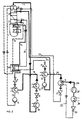
- FIG 1 is a Zweistoffsorptionsstrom according to the prior art (as already stated as Main circuit called) shown and to the additional circuit according to the invention with a circuit of type I expanded.
- Main circuit In the main circuit is in the Hochdruckaustreiber (1) by a heat transfer medium (5) supplied heat from the outside.
- the generated mixed steam of working fluid and sorbent is fed to the rectifier (2) and in several exchange stages (3) almost pure working medium vapor generated.
- This steam is partially released with heat in the return cooler (4) and in the condenser (10) of the main circuit completely liquefied.
- the amount of almost pure working fluid (9) is brought by means of a liquid throttle (11) to the low pressure level and below Heat absorption in a low-pressure evaporator (12) evaporated.
- the low pressure steam thus generated (18) is released from the poor solution (low in equipment) with heat release in the low-pressure absorber (7) (14) recorded.
- the rich solution (15) thus formed is carried out by means of a first solution pump (8) brought to the pressure level of the high pressure expeller.
- the rich solution (15) is first (16) passed through the return cooler (4) (e.g., by piping) and warmed up, then further reheated in the solution heat exchanger (19). After the solution heat exchanger (19), the rich solution (15) in the Hochdruckausustreiber (1) directed.
- heat is removed from the fluid by supplying heat (5).
- the resulting poor solution (14) is returned to the heat in the Hochdruckaustreiber (1) (13), then cooled in the solution heat exchanger (19) to the low pressure level of the main circuit lowered by means of a second throttle (6) and in the low-pressure absorber (7) with heat release enriched again.
- the working fluid formed in the return cooler (4) by partial condensation of the working medium vapor is predominantly or not supplied to the rectifier, but by means of a valve derived (25).
- the derived fontnikaillesstoffenbergkeit (26) is by means of a second auxiliary circuit (27) brought to medium pressure level and fed to the medium-pressure evaporator (28). There it is evaporated with heat absorption to medium temperature level.
- the additional circuit medium pressure steam (29) is in a pressurized medium pressure absorber (22) under Heat output from the poor auxiliary circuit solution (20) absorbed.
- the poor additional circle solution (20) becomes taken from the course of the first exchange stage of the rectifier (2). This can be done through a control valve to be controlled.
- the poor additional circuit solution (20) is by means of a first additional circuit choke (21) lowered to medium pressure level and fed to the medium-pressure absorber (22).
- the im Medium pressure absorber (22) formed rich additional circuit solution (24) by means of a first additional circuit solution pump (23) brought to the high pressure level of the rectifier (2) and in the upper cold Part initiated.
- a first additional circuit solution pump (23) brought to the high pressure level of the rectifier (2) and in the upper cold Part initiated.
- the upper (relatively cold) stage of the rectifier there is a mass and heat exchange between the (additional) rich additional circuit solution and the mixture steam supplied from below instead, which - as known - causes a portion of the mixture vapor is condensed.
- P2 medium-pressure evaporator
- T1 the temperature level in the medium-pressure evaporator
- heat pump is because of the additional circuit lower bridgeable Temperaturhubes given a limiting condition for the temperature level in the evaporator and absorber.
- the selected decoupling of the working fluid from the recooler and the poor Solution for the additional circuit is particularly suitable for retrofitting existing systems.
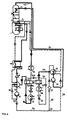
- FIG. 2 shows how the lower temperature lift of the additional circuit between the medium-pressure evaporator and capacitor (compared to the main circuit) by means of a first compression circuit is compensated.
- the medium-pressure evaporator through a cascade heat exchanger (31) replaced.
- the in this condensation process generated first compression cycle working fluid (32) is provided with a first compression circuit throttle (33) brought to low pressure and the first compression circuit evaporator (34) fed and evaporated there under heat absorption.
- the generated first compression circuit steam (36) is brought to the higher pressure with the first mechanical compressor (35) and mentioned first cascade heat exchanger (31).
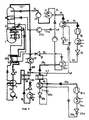
- FIG. 3 shows the temperature deviation between the low-pressure evaporator and the medium-pressure evaporator overcome in the context of a sorption process (circuit type III).
- circuit type III circuit type III
- the working medium high-pressure steam (117) of main circuit and auxiliary circuit is common condensed in a condenser (10).
- a first partial flow of additional working fluid (226) is then provided by means of valve (37). separated.
- the remaining main flow of main circuit / auxiliary circuit working fluid (209) becomes Throttled by means of a liquid throttle (11) and fed to the low-pressure evaporator (12).
- the Low-pressure evaporator (12) is both low-pressure steam (18) of the main circuit and additional circuit low-pressure steam (38) - as a second partial flow of the auxiliary circuit - taken and a Additional low-pressure absorber (44) supplied and there from the poor additional circuit solution (20) is absorbed.
- the in the additional circuit low-pressure absorber (44) dissipated Heat is transferred to the medium-pressure evaporator (28) - here by a liquid circuit with Circulation pump (40) accomplished.
- Mandatory are the temperature levels of Additional circuit low-pressure absorber (44) and medium-pressure evaporator (28) as well as the two partial flows (44) and medium-pressure evaporator (28) and the two partial streams (226, 38) of the additional circuit to each other to agree that the heat transfer is possible.
- the in the additional circle low pressure absorber (44) enriched additional circuit solution (42) is by means of a second additional circuit solution pump (43) brought to the intermediate pressure level of the additional circuit and fed to the medium-pressure absorber (22).
- the pressure-temperature diagram shows that the poor auxiliary circuit solution and the rich solution be guided in their circuits in the opposite direction. This becomes a better heat exchange the solutions used.
- the poor additional circle solution (20) is for this purpose only from the (lowest) the warmest part of the rectifier (2).
- the poor additional circle solution (20) is guided, it is cooled and heat to the rich solution (15) - in addition to the transfer of the poor solution (14) - transferred. This will heat capacity the poor solution (14) free. It is by means of the known technique of recycling (13) in Hochdruckausustreiber (1) used to reduce the amount of heat to be supplied from the outside (5).
- the rich additional circle solution (24) is first (41) above the first Exchange bottom of the rectifier led. Since the rich additional circuit solution (24) supplied undercooled is, the rising Hästoffdämpfe be rich by the heat absorption of the last Additional circuit solution (24) rectified.
- FIG. 4 shows the known method of subcooling the working fluid (9) by low pressure steam (18) in a solution subcooler (59).
- the cooling capacity increased by the hypothermia of the liquid working fluid.
- the residual solution for supercooling be used.
- the rich additional circle solution (24) initiated without previous indirect heat dissipation in the top floor of the exchange.
- the required minimum return heat (q Rth ) refers to 1 kg rectified steam of a single circuit.
- the working medium is ammonia and water is assumed as sorbent.
- the required minimum return heat depends on the desired degree of purity of the rectified steam - here is assumed 99.8%. Since the proportion of co-expelled sorbent - here water - increases with pressure, the minimum return heat increases with the pressure.
- a working line is drawn. In it AP 1 and AP 2 are two working points.
- the operating point AP 1 should show the minimum return heat of a sorption process, which consists of only one single circuit with a low concentration ⁇ 'of the working fluid in the rich solution - in the example of 13%.
- the operating point AP 2 shows the minimum return heat in the situation of the use of the invention, So a sorption process with main circuit and auxiliary circuit, but the minimum return heat based on the rectified amount of steam (1 kg) of a single circuit, its rich solution the same high proportion of working medium has as the rich additional circle solution.
- the rich solution has a concentration of the working medium of 50% - both that of the Additional circle and that of the used for comparison single circuit.
- the otherwise at each of the two operating points AP 1 and AP 2 present minimum return heat an energetic loss.
- the return heat for warming the rich solution used In this case, the rich solution before entering the solution heat exchanger warmed up with the poor solution. However, this is not just the only way Heat. With the solution recycling by the absorber, almost the same effect can be achieved become. In this respect, only an apparent recovery of the return heat is given.
- the working methods according to the invention in all four types of circuit are used to the Reduce loss size into energetic benefits.
- the advantage gained can be different Be kind.
- a benefit is always given by the fact that heat from the outside in the medium pressure evaporator is recorded. As already stated, this is the temperature to be bridged or the usable pressure gradient lower than in the main circuit. It can also heat the rich Solution be transferred. In this case falls by cooling the poor additional circle solution to be won Heat at a higher temperature level than that from the return cooler. The heat output The poor solution to the rich solution to this up to the temperature level of To raise high-pressure exhauster, correspondingly lower. Through this reduction in heat dissipation there is the opportunity to use the amount of heat saved in the expeller positive.
- the known method of solution recycling of the poor solution by the High pressure exhauster applied. However, it is necessary to have the rich solution before entering the Reheat solution heat exchanger by recycling through an absorber. This is common applied method.
- the additional circuit must be quantitative be designed so that it in the rectifier, the heat difference between AP and AP 2 can record.
- the incomplete rectification is an interpretation to a slightly larger Heat absorption as the minimum return heat makes sense.
- the rich additional circuit solution is undercooled introduced into the rectifier, the loss size can continue past the AP 2 working point be reduced, the additional circuit designed for a correspondingly greater heat absorption must become.
- This possibility is given by the rich additional circle solution (after removal from the absorber) is introduced without further heat input into the rectifier. Leaves the use case a free choice of Temperaturhubes, it is favorable, its rich additional circle solution a proportion of working fluid of approx.
- the additional circle can be designed so that in its poor additional circle solution, the proportion of the working fluid close to the proportion of the rich solution (see Figures 2-4 and 7) or with this matches (see Figure 6, 8). With low work agent content in the rich solution and one high proportion in the rich additional circle solution - as selected in the example 5 - results in Additional circle a large degassing width. This can be exploited, the enrichment in two Steps by means of two Rajnikabsorbern perform (Fig. 9).
- the poor additional circuit solution (20) is by means of a first auxiliary circuit throttle (21) lowered to the medium-pressure level and in the medium-pressure absorber (22) headed.
- this circuit is shown in FIG. 3 shown and explained comparable.
- the additional recovery of the absorber heat of the Additional circle is useful if the amount of poor additional circle solution significantly smaller is the difference between the rich and the poor.
- FIG. 7 shows the known two-time use of the heat supplied to the process, by a resorption subcircuit between the low-pressure evaporator (12) and the high-pressure absorber (7) is inserted, this being done in a circuit of the type II.
- the additional circuit consists - according to the prior art - from a resorber (45), a Resorptionsnikansskorleyer (46) and a degasser (49) and the line for the rich Resorptionsnikans (47) with Resorptionsnikdrossel (48) and the line for the poor Resorptionsnikans (50) with resorption cycle solution pump (51).
- the expelled in the degasser (49) Resorptionsnikdampf (39) is fed to the pressurized low-pressure absorber (7) and absorbed.
- the resorber (45) is from the medium pressure evaporator (22) medium pressure steam of the Main run and the auxiliary circuit (118) supplied.
- solution heat exchangers (6 1 a, 6 1 b) formed in two different temperature levels.
- the solution heat exchanger (61a) of lower temperature levels go through increased amounts of liquid, those of the upper (61b) temperature levels stay unchanged.
- a third solution pump (65) and a fourth throttle (64) are between low pressure and medium pressure and between medium pressure and high pressure also a second solution pump (62) and a third throttle (63) necessary.
- a partial stream of rich home / poor Additional circuit solution (30) is by means of valve (72) after the solution heat exchanger (61a) of the lower Temperature stage separated and in said condenser / expeller combination (57) for expulsion initiated.
- the second partial flow taken from the condenser / expeller combination (57) (70) poor solution is combined (14a) with the poor solution coming from the high pressure expeller (14) via the way solution heat exchanger (61a) of the lower temperature stage and fourth throttle (64) fed to the low-pressure absorber (7).
- FIG 9 is shown how the absorption of the additional circuit in the circuit type I in two pressure stages, first in a medium pressure absorber (22a) of lower pressure and then in the first medium pressure absorber (22).
- the first mentioned medium-pressure absorber (22a) lower pressure enriched additional circuit solution (42) is by means of the second additional circuit solution pump (43) raised to the higher medium pressure level and then by means of valve (69) in two partial streams divided.
- the first partial flow (71) enriched additional circuit solution is the medium-pressure absorber (22) supplied, the second (71 a) substream enriched additional circuit solution to the middle part of the rectifier (2), wherein this partial flow (71) previously by means of third Rajariaspumpe (23 a) raised to rectifier pressure.
- each additional circuit sub-stream (68, 68 a) is by means of a second and third auxiliary circuit throttle (27, 27a) on the respective medium-pressure absorbers (22, 22a) lowered appropriate pressure and introduced in a respective cascade heat exchanger (31, 31 a).
- each cascade heat exchanger (31 or 31 a) is by heat absorption thank Vietnamesestoffstoffdampf (29 or 29a) generated.
- the cascade heat exchangers (31, 31a) finds a heat transfer from the condensation process of the respective compression circuit to the respective evaporation process of the additional circle instead.
- the in the respective condensation process generated compression cycle working fluid (32, 32a) is supplied with a respective one Compression circuit throttle (33, 33 a) brought to low pressure and the respective compression circuit evaporator (34, 34a) of the respective compression circuit fed and there under heat absorption evaporated.
- In the associated compression circuits are further process variants conceivable (e.g., a common evaporator).
- the quantity distribution of the two partial streams can be different. It depends on the options described for Figure 5.
- a solution-side series connection of 1925absorbem is also without associated compression circuit applicable, but particularly advantageous if the temperature difference between the Additional absorbers and the low-pressure absorber of the main circuit by means of mechanical compression circuits should be bridged because of the required compression power and work reduced compared to a circuit with only one additional absorber (further).
- the additional-circuit absorber (22) is supplied with medium-pressure steam (29b) from a first separator (75).
- This first separator (75) is supplied to a first partial stream (79) poor solution, the previously after Outflow from the Hochlichausustreiber (1) from the main flow (14) poor solution by means of valve (81) regulated was separated and lowered by means of fourth throttle (82) to medium pressure.
- the first separator (75) the two-phase mixture resulting from depressurization becomes poorer in a third stream (85) Solution and medium pressure mixed steam separated.
- For rectification of the medium pressure steam is a first Partial flow (76) rich solution via a first separator (75) associated output column (80) in the first separator (75) introduced.
- the first partial stream (76) rich solution is from the main stream (15) the rich solution after the heat absorption in the medium-pressure absorber (22) by means of valve (77) separated and lowered by fifth throttle (78) to medium pressure.
- the main stream of poor solution (14) is lowered with second throttle (63) to medium pressure and with the from the first separator (75) draining third stream (85) of poor solution united by the solution heat exchanger (19a) of the lower Temperature range passed.
- the heat exchange between poor (14) and rich solution (15) is each in a solution heat exchanger of the lower temperature range (19a) and one of the upper temperature range (19b) made. Between these two solution heat exchangers by means of valve (83) controlled by the main stream of rich solution (15) a second partial stream of rich solution (84) separated and introduced into the hot part of the rectifier (2) - shown here above the bottom Soil (3).
- the improvement is due to several factors:
- the first factor is that for the Expulsion of the additional circulation high-pressure steam in the rectifier no recooling heat is needed and thus for this part the heat ratio is significantly better than the heat ratio of a single one Circuit.
- the second factor is triggered by the bypassing of the first partial flow (76). the rich solution to the solution heat exchangers (19a, 19b). This partial flow takes the remindkühluer on, which is obtained in the rectification of the separated in the first separator mixed steam.
- This bypass can heat balance in the solution heat exchanger of the lower temperature range (19a) be largely or completely offset by poor and rich solutions. This is it is possible to warm up the rich solution more strongly than in a single cycle in comparable Temperature range is possible.
- the fourth factor is the magnification of the To call degassing width in the first separator (75).
- the associated lower solution circulation is favorable in view of the heat ratio and the construction cost of the solution heat exchanger.
- this factor is less important.
- the negative influence of the rectification on the heat ratio quite significant compared to a single-loop sorption system.
Landscapes
- Engineering & Computer Science (AREA)
- Physics & Mathematics (AREA)
- Mechanical Engineering (AREA)
- Thermal Sciences (AREA)
- General Engineering & Computer Science (AREA)
- Sorption Type Refrigeration Machines (AREA)
- Medicines Containing Plant Substances (AREA)
Applications Claiming Priority (4)
| Application Number | Priority Date | Filing Date | Title |
|---|---|---|---|
| DE102004023403 | 2004-05-12 | ||
| DE102004023403 | 2004-05-12 | ||
| DE102004039997 | 2004-08-18 | ||
| DE102004039997A DE102004039997B4 (de) | 2004-05-12 | 2004-08-18 | Arbeitsverfahren einer Sorptionsanlage |
Publications (3)
| Publication Number | Publication Date |
|---|---|
| EP1596141A2 true EP1596141A2 (fr) | 2005-11-16 |
| EP1596141A3 EP1596141A3 (fr) | 2006-11-08 |
| EP1596141B1 EP1596141B1 (fr) | 2010-11-24 |
Family
ID=34936432
Family Applications (1)
| Application Number | Title | Priority Date | Filing Date |
|---|---|---|---|
| EP05010312A Expired - Lifetime EP1596141B1 (fr) | 2004-05-12 | 2005-05-12 | Mise en oeuvre d'un appareil à sorption |
Country Status (2)
| Country | Link |
|---|---|
| EP (1) | EP1596141B1 (fr) |
| DE (1) | DE102004039997B4 (fr) |
Cited By (1)
| Publication number | Priority date | Publication date | Assignee | Title |
|---|---|---|---|---|
| DE102014101648B3 (de) * | 2014-02-11 | 2015-03-26 | Technische Universität Dresden | Absorptionskältemaschine und Verfahren zur Erzeugung von Kälte |
Families Citing this family (2)
| Publication number | Priority date | Publication date | Assignee | Title |
|---|---|---|---|---|
| DE102009023929A1 (de) | 2009-06-04 | 2010-12-09 | Stürzebecher, Wolfgang, Dr. | Absorptionskälteaggregat |
| DE102016009681B3 (de) * | 2016-08-06 | 2017-10-19 | Anno von Reth | Arbeitsverfahren einer Sorptionsanlage mit Haupt- und Zusatzkreislauf zur Kälteerzeugung |
Citations (1)
| Publication number | Priority date | Publication date | Assignee | Title |
|---|---|---|---|---|
| DE10219263A1 (de) | 2002-04-30 | 2003-11-20 | Hans Foerster | Verfahren und Vorrichtung für die nichtadiabate Rektifikation ohne Rücklauferzeugung |
Family Cites Families (2)
| Publication number | Priority date | Publication date | Assignee | Title |
|---|---|---|---|---|
| DD251195A1 (de) * | 1986-07-16 | 1987-11-04 | Schwermasch Liebknecht Veb K | Verfahren zur ruecklauferzeugung bei der thermischen trennung fluessiger gemische |
| DE10151001A1 (de) * | 2001-10-16 | 2003-04-24 | Volkswagen Ag | Kühlverfahren für einen Verbrennungsmotor und Kühlmittelkreislauf |
-
2004
- 2004-08-18 DE DE102004039997A patent/DE102004039997B4/de not_active Expired - Lifetime
-
2005
- 2005-05-12 EP EP05010312A patent/EP1596141B1/fr not_active Expired - Lifetime
Patent Citations (1)
| Publication number | Priority date | Publication date | Assignee | Title |
|---|---|---|---|---|
| DE10219263A1 (de) | 2002-04-30 | 2003-11-20 | Hans Foerster | Verfahren und Vorrichtung für die nichtadiabate Rektifikation ohne Rücklauferzeugung |
Cited By (1)
| Publication number | Priority date | Publication date | Assignee | Title |
|---|---|---|---|---|
| DE102014101648B3 (de) * | 2014-02-11 | 2015-03-26 | Technische Universität Dresden | Absorptionskältemaschine und Verfahren zur Erzeugung von Kälte |
Also Published As
| Publication number | Publication date |
|---|---|
| DE102004039997B4 (de) | 2006-06-14 |
| EP1596141B1 (fr) | 2010-11-24 |
| EP1596141A3 (fr) | 2006-11-08 |
| DE102004039997A1 (de) | 2005-12-08 |
Similar Documents
| Publication | Publication Date | Title |
|---|---|---|
| DE278076C (fr) | ||
| DE2754626C2 (de) | Mit einer Energiequelle relativ niedriger Temperatur, insbesondere Solarenergie, arbeitende Kälteanlage | |
| DE602004006266T2 (de) | Verfahren und vorrichtung zur gleichzeitigen produktion eines erdgases zur verflüssigung und einer flüssigen fraktion aus erdgas | |
| DE69511962T2 (de) | System und Vorrichtung zur Umwandlung von thermischer Energie in mechanische oder elektrische Leistung | |
| DE69126140T2 (de) | Absorptionskreislauf mit Dampfaustausch und doppeltem Generator-Absorber-Wärmeaustausch | |
| DE1140957B (de) | Absorptionskuehlsystem und Verfahren fuer den Betrieb desselben | |
| CH636184A5 (de) | Verfahren zur rektivikation des kaeltemittel-dampfes in einer absorptionskaelteanlage. | |
| EP0531293B1 (fr) | Procede thermique d'evaporation, de condensation et d'absorption, avec combinaison de ces processus | |
| EP1596141B1 (fr) | Mise en oeuvre d'un appareil à sorption | |
| CH712029A1 (de) | Nieder-Temperatur-Destillationsanlage. | |
| DE69921871T2 (de) | Absorptionskälteanlage mit Kupplung von Kondensat und Lösung | |
| DE3536953C1 (en) | Resorption-type heat converter installation with two solution circuits | |
| DE3229883A1 (de) | Verfahren und einrichtung zur herstellung von gereinigtem aethylen | |
| DE102005005409B4 (de) | Arbeitsverfahren einer Sorptionsmaschine | |
| DE102016009681B3 (de) | Arbeitsverfahren einer Sorptionsanlage mit Haupt- und Zusatzkreislauf zur Kälteerzeugung | |
| EP2543830B1 (fr) | Procédé de fonctionnement d'un cycle de production d'énergie de sorption utilisant un mélange binaire à base d'ammoniaque et d'eau | |
| DE2725253A1 (de) | Verfahren zum trennen von synthesegas | |
| DE4003120C1 (en) | Liq. mixture thermal separation method - heating re-concentrating solvent stream and mixture stream before combining at end for supply | |
| EP1265042B1 (fr) | Système frigorifique utilisant un mélange de deux ou plusieurs composants avec au moins une unité de compresseur | |
| DE1501008C (de) | Absorptionskälteanlage | |
| AT90619B (de) | Verfahren zur ununterbrochenen Erzeugung von Kälte und Wärme oder auch von Arbeit mittels der Absorptionsmaschine. | |
| DE1751375C (de) | Absorptionskälteanlage | |
| AT154276B (de) | Absorptionskältemaschine. | |
| DE1601141A1 (de) | Verfahren zum Abkuehlen einer verdampfbare Anteile enthaltenden Fluessigkeit | |
| WO2005093342A2 (fr) | Installation de compression/d'absorption |
Legal Events
| Date | Code | Title | Description |
|---|---|---|---|
| PUAI | Public reference made under article 153(3) epc to a published international application that has entered the european phase |
Free format text: ORIGINAL CODE: 0009012 |
|
| AK | Designated contracting states |
Kind code of ref document: A2 Designated state(s): AT BE BG CH CY CZ DE DK EE ES FI FR GB GR HU IE IS IT LI LT LU MC NL PL PT RO SE SI SK TR |
|
| AX | Request for extension of the european patent |
Extension state: AL BA HR LV MK YU |
|
| RTI1 | Title (correction) |
Free format text: WORKING METHOD FOR A SORPTION APPARATUS |
|
| PUAL | Search report despatched |
Free format text: ORIGINAL CODE: 0009013 |
|
| AK | Designated contracting states |
Kind code of ref document: A3 Designated state(s): AT BE BG CH CY CZ DE DK EE ES FI FR GB GR HU IE IS IT LI LT LU MC NL PL PT RO SE SI SK TR |
|
| AX | Request for extension of the european patent |
Extension state: AL BA HR LV MK YU |
|
| 17P | Request for examination filed |
Effective date: 20070502 |
|
| AKX | Designation fees paid | ||
| RBV | Designated contracting states (corrected) |
Designated state(s): AT BE BG CH CY LI |
|
| RBV | Designated contracting states (corrected) |
Designated state(s): ES FR GB IT TR |
|
| REG | Reference to a national code |
Ref country code: DE Ref legal event code: 8566 |
|
| 17Q | First examination report despatched |
Effective date: 20071115 |
|
| GRAP | Despatch of communication of intention to grant a patent |
Free format text: ORIGINAL CODE: EPIDOSNIGR1 |
|
| RTI1 | Title (correction) |
Free format text: WORKING METHOD FOR A SORPTION APPARATUS |
|
| GRAS | Grant fee paid |
Free format text: ORIGINAL CODE: EPIDOSNIGR3 |
|
| GRAA | (expected) grant |
Free format text: ORIGINAL CODE: 0009210 |
|
| AK | Designated contracting states |
Kind code of ref document: B1 Designated state(s): ES FR GB IT TR |
|
| REG | Reference to a national code |
Ref country code: GB Ref legal event code: FG4D Free format text: NOT ENGLISH |
|
| PG25 | Lapsed in a contracting state [announced via postgrant information from national office to epo] |
Ref country code: ES Free format text: LAPSE BECAUSE OF FAILURE TO SUBMIT A TRANSLATION OF THE DESCRIPTION OR TO PAY THE FEE WITHIN THE PRESCRIBED TIME-LIMIT Effective date: 20110307 |
|
| PGFP | Annual fee paid to national office [announced via postgrant information from national office to epo] |
Ref country code: GB Payment date: 20110324 Year of fee payment: 7 Ref country code: FR Payment date: 20110419 Year of fee payment: 7 |
|
| PLBE | No opposition filed within time limit |
Free format text: ORIGINAL CODE: 0009261 |
|
| STAA | Information on the status of an ep patent application or granted ep patent |
Free format text: STATUS: NO OPPOSITION FILED WITHIN TIME LIMIT |
|
| 26N | No opposition filed |
Effective date: 20110825 |
|
| PG25 | Lapsed in a contracting state [announced via postgrant information from national office to epo] |
Ref country code: IT Free format text: LAPSE BECAUSE OF FAILURE TO SUBMIT A TRANSLATION OF THE DESCRIPTION OR TO PAY THE FEE WITHIN THE PRESCRIBED TIME-LIMIT Effective date: 20101124 |
|
| GBPC | Gb: european patent ceased through non-payment of renewal fee |
Effective date: 20120512 |
|
| REG | Reference to a national code |
Ref country code: FR Ref legal event code: ST Effective date: 20130131 |
|
| PG25 | Lapsed in a contracting state [announced via postgrant information from national office to epo] |
Ref country code: FR Free format text: LAPSE BECAUSE OF NON-PAYMENT OF DUE FEES Effective date: 20120531 Ref country code: GB Free format text: LAPSE BECAUSE OF NON-PAYMENT OF DUE FEES Effective date: 20120512 |
|
| PG25 | Lapsed in a contracting state [announced via postgrant information from national office to epo] |
Ref country code: TR Free format text: LAPSE BECAUSE OF FAILURE TO SUBMIT A TRANSLATION OF THE DESCRIPTION OR TO PAY THE FEE WITHIN THE PRESCRIBED TIME-LIMIT Effective date: 20101124 |