EP1596123B1 - Gasflasche für Schweißgeräte - Google Patents
Gasflasche für Schweißgeräte Download PDFInfo
- Publication number
- EP1596123B1 EP1596123B1 EP05008477.1A EP05008477A EP1596123B1 EP 1596123 B1 EP1596123 B1 EP 1596123B1 EP 05008477 A EP05008477 A EP 05008477A EP 1596123 B1 EP1596123 B1 EP 1596123B1
- Authority
- EP
- European Patent Office
- Prior art keywords
- gas cylinder
- gas
- regulator
- adapter
- constructed
- Prior art date
- Legal status (The legal status is an assumption and is not a legal conclusion. Google has not performed a legal analysis and makes no representation as to the accuracy of the status listed.)
- Expired - Fee Related
Links
Images


Classifications
-
- B—PERFORMING OPERATIONS; TRANSPORTING
- B23—MACHINE TOOLS; METAL-WORKING NOT OTHERWISE PROVIDED FOR
- B23K—SOLDERING OR UNSOLDERING; WELDING; CLADDING OR PLATING BY SOLDERING OR WELDING; CUTTING BY APPLYING HEAT LOCALLY, e.g. FLAME CUTTING; WORKING BY LASER BEAM
- B23K9/00—Arc welding or cutting
- B23K9/32—Accessories
- B23K9/325—Devices for supplying or evacuating shielding gas
-
- F—MECHANICAL ENGINEERING; LIGHTING; HEATING; WEAPONS; BLASTING
- F17—STORING OR DISTRIBUTING GASES OR LIQUIDS
- F17C—VESSELS FOR CONTAINING OR STORING COMPRESSED, LIQUEFIED OR SOLIDIFIED GASES; FIXED-CAPACITY GAS-HOLDERS; FILLING VESSELS WITH, OR DISCHARGING FROM VESSELS, COMPRESSED, LIQUEFIED, OR SOLIDIFIED GASES
- F17C2201/00—Vessel construction, in particular geometry, arrangement or size
- F17C2201/01—Shape
- F17C2201/0104—Shape cylindrical
- F17C2201/0109—Shape cylindrical with exteriorly curved end-piece
-
- F—MECHANICAL ENGINEERING; LIGHTING; HEATING; WEAPONS; BLASTING
- F17—STORING OR DISTRIBUTING GASES OR LIQUIDS
- F17C—VESSELS FOR CONTAINING OR STORING COMPRESSED, LIQUEFIED OR SOLIDIFIED GASES; FIXED-CAPACITY GAS-HOLDERS; FILLING VESSELS WITH, OR DISCHARGING FROM VESSELS, COMPRESSED, LIQUEFIED, OR SOLIDIFIED GASES
- F17C2201/00—Vessel construction, in particular geometry, arrangement or size
- F17C2201/01—Shape
- F17C2201/0104—Shape cylindrical
- F17C2201/0119—Shape cylindrical with flat end-piece
-
- F—MECHANICAL ENGINEERING; LIGHTING; HEATING; WEAPONS; BLASTING
- F17—STORING OR DISTRIBUTING GASES OR LIQUIDS
- F17C—VESSELS FOR CONTAINING OR STORING COMPRESSED, LIQUEFIED OR SOLIDIFIED GASES; FIXED-CAPACITY GAS-HOLDERS; FILLING VESSELS WITH, OR DISCHARGING FROM VESSELS, COMPRESSED, LIQUEFIED, OR SOLIDIFIED GASES
- F17C2201/00—Vessel construction, in particular geometry, arrangement or size
- F17C2201/05—Size
- F17C2201/058—Size portable (<30 l)
-
- F—MECHANICAL ENGINEERING; LIGHTING; HEATING; WEAPONS; BLASTING
- F17—STORING OR DISTRIBUTING GASES OR LIQUIDS
- F17C—VESSELS FOR CONTAINING OR STORING COMPRESSED, LIQUEFIED OR SOLIDIFIED GASES; FIXED-CAPACITY GAS-HOLDERS; FILLING VESSELS WITH, OR DISCHARGING FROM VESSELS, COMPRESSED, LIQUEFIED, OR SOLIDIFIED GASES
- F17C2205/00—Vessel construction, in particular mounting arrangements, attachments or identifications means
- F17C2205/01—Mounting arrangements
- F17C2205/0103—Exterior arrangements
- F17C2205/0111—Boxes
-
- F—MECHANICAL ENGINEERING; LIGHTING; HEATING; WEAPONS; BLASTING
- F17—STORING OR DISTRIBUTING GASES OR LIQUIDS
- F17C—VESSELS FOR CONTAINING OR STORING COMPRESSED, LIQUEFIED OR SOLIDIFIED GASES; FIXED-CAPACITY GAS-HOLDERS; FILLING VESSELS WITH, OR DISCHARGING FROM VESSELS, COMPRESSED, LIQUEFIED, OR SOLIDIFIED GASES
- F17C2205/00—Vessel construction, in particular mounting arrangements, attachments or identifications means
- F17C2205/01—Mounting arrangements
- F17C2205/0123—Mounting arrangements characterised by number of vessels
- F17C2205/0126—One vessel
-
- F—MECHANICAL ENGINEERING; LIGHTING; HEATING; WEAPONS; BLASTING
- F17—STORING OR DISTRIBUTING GASES OR LIQUIDS
- F17C—VESSELS FOR CONTAINING OR STORING COMPRESSED, LIQUEFIED OR SOLIDIFIED GASES; FIXED-CAPACITY GAS-HOLDERS; FILLING VESSELS WITH, OR DISCHARGING FROM VESSELS, COMPRESSED, LIQUEFIED, OR SOLIDIFIED GASES
- F17C2205/00—Vessel construction, in particular mounting arrangements, attachments or identifications means
- F17C2205/01—Mounting arrangements
- F17C2205/0153—Details of mounting arrangements
- F17C2205/0157—Details of mounting arrangements for transport
- F17C2205/0165—Details of mounting arrangements for transport with handgrip
-
- F—MECHANICAL ENGINEERING; LIGHTING; HEATING; WEAPONS; BLASTING
- F17—STORING OR DISTRIBUTING GASES OR LIQUIDS
- F17C—VESSELS FOR CONTAINING OR STORING COMPRESSED, LIQUEFIED OR SOLIDIFIED GASES; FIXED-CAPACITY GAS-HOLDERS; FILLING VESSELS WITH, OR DISCHARGING FROM VESSELS, COMPRESSED, LIQUEFIED, OR SOLIDIFIED GASES
- F17C2205/00—Vessel construction, in particular mounting arrangements, attachments or identifications means
- F17C2205/03—Fluid connections, filters, valves, closure means or other attachments
- F17C2205/0302—Fittings, valves, filters, or components in connection with the gas storage device
- F17C2205/0323—Valves
-
- F—MECHANICAL ENGINEERING; LIGHTING; HEATING; WEAPONS; BLASTING
- F17—STORING OR DISTRIBUTING GASES OR LIQUIDS
- F17C—VESSELS FOR CONTAINING OR STORING COMPRESSED, LIQUEFIED OR SOLIDIFIED GASES; FIXED-CAPACITY GAS-HOLDERS; FILLING VESSELS WITH, OR DISCHARGING FROM VESSELS, COMPRESSED, LIQUEFIED, OR SOLIDIFIED GASES
- F17C2205/00—Vessel construction, in particular mounting arrangements, attachments or identifications means
- F17C2205/03—Fluid connections, filters, valves, closure means or other attachments
- F17C2205/0302—Fittings, valves, filters, or components in connection with the gas storage device
- F17C2205/0338—Pressure regulators
-
- F—MECHANICAL ENGINEERING; LIGHTING; HEATING; WEAPONS; BLASTING
- F17—STORING OR DISTRIBUTING GASES OR LIQUIDS
- F17C—VESSELS FOR CONTAINING OR STORING COMPRESSED, LIQUEFIED OR SOLIDIFIED GASES; FIXED-CAPACITY GAS-HOLDERS; FILLING VESSELS WITH, OR DISCHARGING FROM VESSELS, COMPRESSED, LIQUEFIED, OR SOLIDIFIED GASES
- F17C2205/00—Vessel construction, in particular mounting arrangements, attachments or identifications means
- F17C2205/03—Fluid connections, filters, valves, closure means or other attachments
- F17C2205/0302—Fittings, valves, filters, or components in connection with the gas storage device
- F17C2205/037—Quick connecting means, e.g. couplings
- F17C2205/0373—Adapters
-
- F—MECHANICAL ENGINEERING; LIGHTING; HEATING; WEAPONS; BLASTING
- F17—STORING OR DISTRIBUTING GASES OR LIQUIDS
- F17C—VESSELS FOR CONTAINING OR STORING COMPRESSED, LIQUEFIED OR SOLIDIFIED GASES; FIXED-CAPACITY GAS-HOLDERS; FILLING VESSELS WITH, OR DISCHARGING FROM VESSELS, COMPRESSED, LIQUEFIED, OR SOLIDIFIED GASES
- F17C2209/00—Vessel construction, in particular methods of manufacturing
- F17C2209/22—Assembling processes
- F17C2209/228—Assembling processes by screws, bolts or rivets
-
- F—MECHANICAL ENGINEERING; LIGHTING; HEATING; WEAPONS; BLASTING
- F17—STORING OR DISTRIBUTING GASES OR LIQUIDS
- F17C—VESSELS FOR CONTAINING OR STORING COMPRESSED, LIQUEFIED OR SOLIDIFIED GASES; FIXED-CAPACITY GAS-HOLDERS; FILLING VESSELS WITH, OR DISCHARGING FROM VESSELS, COMPRESSED, LIQUEFIED, OR SOLIDIFIED GASES
- F17C2223/00—Handled fluid before transfer, i.e. state of fluid when stored in the vessel or before transfer from the vessel
- F17C2223/01—Handled fluid before transfer, i.e. state of fluid when stored in the vessel or before transfer from the vessel characterised by the phase
- F17C2223/0107—Single phase
- F17C2223/0123—Single phase gaseous, e.g. CNG, GNC
-
- F—MECHANICAL ENGINEERING; LIGHTING; HEATING; WEAPONS; BLASTING
- F17—STORING OR DISTRIBUTING GASES OR LIQUIDS
- F17C—VESSELS FOR CONTAINING OR STORING COMPRESSED, LIQUEFIED OR SOLIDIFIED GASES; FIXED-CAPACITY GAS-HOLDERS; FILLING VESSELS WITH, OR DISCHARGING FROM VESSELS, COMPRESSED, LIQUEFIED, OR SOLIDIFIED GASES
- F17C2223/00—Handled fluid before transfer, i.e. state of fluid when stored in the vessel or before transfer from the vessel
- F17C2223/03—Handled fluid before transfer, i.e. state of fluid when stored in the vessel or before transfer from the vessel characterised by the pressure level
- F17C2223/035—High pressure (>10 bar)
-
- F—MECHANICAL ENGINEERING; LIGHTING; HEATING; WEAPONS; BLASTING
- F17—STORING OR DISTRIBUTING GASES OR LIQUIDS
- F17C—VESSELS FOR CONTAINING OR STORING COMPRESSED, LIQUEFIED OR SOLIDIFIED GASES; FIXED-CAPACITY GAS-HOLDERS; FILLING VESSELS WITH, OR DISCHARGING FROM VESSELS, COMPRESSED, LIQUEFIED, OR SOLIDIFIED GASES
- F17C2250/00—Accessories; Control means; Indicating, measuring or monitoring of parameters
- F17C2250/04—Indicating or measuring of parameters as input values
- F17C2250/0404—Parameters indicated or measured
- F17C2250/043—Pressure
-
- F—MECHANICAL ENGINEERING; LIGHTING; HEATING; WEAPONS; BLASTING
- F17—STORING OR DISTRIBUTING GASES OR LIQUIDS
- F17C—VESSELS FOR CONTAINING OR STORING COMPRESSED, LIQUEFIED OR SOLIDIFIED GASES; FIXED-CAPACITY GAS-HOLDERS; FILLING VESSELS WITH, OR DISCHARGING FROM VESSELS, COMPRESSED, LIQUEFIED, OR SOLIDIFIED GASES
- F17C2270/00—Applications
- F17C2270/05—Applications for industrial use
- F17C2270/0545—Tools
-
- F—MECHANICAL ENGINEERING; LIGHTING; HEATING; WEAPONS; BLASTING
- F17—STORING OR DISTRIBUTING GASES OR LIQUIDS
- F17C—VESSELS FOR CONTAINING OR STORING COMPRESSED, LIQUEFIED OR SOLIDIFIED GASES; FIXED-CAPACITY GAS-HOLDERS; FILLING VESSELS WITH, OR DISCHARGING FROM VESSELS, COMPRESSED, LIQUEFIED, OR SOLIDIFIED GASES
- F17C2270/00—Applications
- F17C2270/07—Applications for household use
- F17C2270/0745—Gas bottles
Definitions
- the present invention relates generally to welding systems and, more particularly, to a gas cylinder for providing shielding gas to a weld.
- US 3 731 718 A discloses an adapter connector for connecting a reserve gas supply into a gas system e.g. for a mobile home or a camper.
- DE 197 27 847 A1 shows a closure for a gas cylinder including an adapter and a pressure gauge.
- US 5 591 171 A shows an apparatus for measuring pressures of fluid materials in medical procedures.
- welder power sources have become increasingly portable in recent years. This portability is largely the result of lighter unit weight and improved electrical components.
- One advancement in the area of electrical components has been the incorporation of inverter-type power sources.
- the application of an inverter power source has reduced the size and weight of welders and created usable space within the confines of the housing, while maintaining the ability to generate the outputs required for welding.
- Improvements in wire feeder technology have also improved the ease of use and portability of a welder.
- Wire welding is generally believed to be easier to learn than conventional stick welding and as such, relatively inexperienced artisans can produce adequate results in relatively little time. As a result, due to the ease of use and versatility of application, many users prefer wire welding over conventional stick welding.
- any work environment is always at a premium. Whether the welder is used in the hobbyist's garage or the machine shop of an industrial plant, the size of the unit is always a design consideration.
- the space used by a welder is not limited to the dimensions of the power source itself but includes the ancillaries related to welding processes such as cables, consumables, and gas cylinders. The space required for the storage and maintenance of these items is another consideration associated with many welders.
- Shielding gas cylinders provide gas to the welding process. This gas essentially encapsulates the welding process in order to protect the integrity of the weld from contaminants and also enhances arc performance during a welding process.
- the shielding gas is generally provided in very large and very heavy cylinders.
- the cylinders are constructed ruggedly to withstand the high pressure of the gas contained therein and the rigors of the workplace.
- a regulator and valve assembly are typically attached to the gas cylinder and allow the operator of the welding power source to control the amount of gas supplied to the welding process.
- US 3,731,718 discloses a gas cylinder assembly for gas heating systems, which comprises a gas cylinder, a regulator, an adapter, and a value.
- GB 2 151 752 A discloses a gas flow regulating assembly comprising an adjusting screw.
- the present invention is directed to a shielding gas cylinder that solves the aforementioned drawbacks.
- an adapter for a shielding gas system of a welding-type device has a passage extending through a body and fluidly connects a first end and a second end.
- the first end is constructed to be connected to a gas cylinder and the second end is constructed to be connected to a regulator with the body extending between the first and second ends.
- a nipple extends from the body into a recess formed in the first end and is constructed to operatively engage a valve of the gas cylinder.
- a shielding gas system for a welding-type device has a valve connected to a gas cylinder and biased to a closed position and a coupler constructed to bias the valve open when the coupler is connected to the gas cylinder.
- a shielding gas system for a welding device includes a gas bottle having a first end having an opening and a second closed end. A body extends from the first end to the second closed end and a valve is disposed in the opening of the first end.
- the shielding gas system includes an adapter constructed to automatically open the valve when connected about the first end of the gas bottle.
- a welding device having a housing enclosing a power source constructed to supply a welding power.
- a gas cylinder is attached to the housing and constructed to provide a shielding gas.
- the gas cylinder has a length that is less than a length of a side of the housing.
- a method of providing shielding gas to a weld includes initiating a welding arc and opening a shielding gas path to a gas system and providing the gas immediately upon connection of a gas source to a welding-type device.
- a welding-type device that has means for generating a welding power and means for providing shielding gas to a weld.
- a means for fluidly connecting the means for providing shielding gas is included that communicates shielding gas to the means for generating welding power upon a connection of the means for providing shielding gas to the means for generating welding power.
- the present invention provides a shielding gas cylinder that is lightweight and easily transportable.
- welding devices not only includes welders but also includes any system that requires high power outputs that can benefit from the use of a compressed shielding gas. Such systems can include heating and cutting systems.
- Description of a welding-type apparatus illustrates just one embodiment in which the present invention may be implemented.
- Welding device 10 includes a housing 12 enclosing the internal components of the welding device under a cover 14.
- the welding device 10 includes a handle 16 for transporting the welding system from one location to another.
- the welding device includes a torch 18 as well as a work clamp 20.
- the work clamp 20 is configured to complete an electrical circuit from torch 18 through workpiece 22.
- a pair of cables 24 and 26 connects the torch 18 and work clamp 20 to the housing 12, respectively.
- a power cable 28 extends from welding device 10 and is connectable to a variety of inputs. As shown, power cable 28 includes a plug 30 constructed to engage an electrical outlet and supply power to welding device 10 from a power grid. It is understood power cable 28 can be configured to communicate power to welding device 10 from any type of power source, including an engine driven generator, a power grid, a battery, etc.
- Fig. 2 shows welding device 10 with cover 14 removed therefrom. Having cover 14 removed exposes an internal cavity 32 of welding device 10.
- a shroud 34 separates a majority of internal cavity 32 so that removing cover 14 does not expose a majority of the electronic components of the welding device.
- a wire guide 36 and a wire feed 38 are positioned proximate the connection of cable 24 in housing 12.
- a guide wire 40 is drawn from a spool 42 by wire feed 38 to the torch through cable 24.
- Shroud 34 has a curved portion 44 to accommodate the positioning of spool 42 on a hub 46 of welding device 10.
- a shielding gas system 47 includes a gas cylinder 48 constructed to snuggly engage a first portion 50 of a recess 51 formed in shroud 34.
- gas cylinder 48 is shown in a generally horizontal orientation relative to welding device 10, such an orientation is merely exemplary. It is understood that gas cylinder 48 could be positioned in any orientation and could be located entirely within a perimeter 52 of housing 12 as shown, partially within housing 12, or external to the housing, if desired.
- Shielding gas system 47 includes an adapter 54 and a regulator 56.
- Adapter 54 is fluidly connected between gas cylinder 48 and regulator 56 of shielding gas system 47.
- Adapter 54 engages gas cylinder 48 and allows shielding gas to flow from gas cylinder 48 to regulator 56 immediately upon connection thereto, as will later be described in more detail with reference to Figs. 4-7 and 9.
- Adapter 54 is constructed to be snuggly positioned in a second portion 58 of recess 51.
- Regulator 56 is positioned in a third portion 60 of recess 51 and is fluidly connected to the torch of welding device 10 via a hose 61 and controls the amount of shielding gas provided to the torch during a welding operation.
- a valve (not shown) is fluidly connected between torch 18 and regulator 56 such that the flow of shielding gas from shielding gas system 47 to torch 18 is only allowed when an operator has depressed a trigger or other actuator of torch 18.
- Shroud 34 has a first boss 62 and a second boss 64 which generally flank gas cylinder 48.
- a strap 66 has a first end 68 pivotally connected to first boss 62 and a second end 70 constructed to engage second boss 64 of shroud 34.
- a latch 72 is pivotally connected to second end 70 of strap 66 and is constructed to removably engage second boss 64 of shroud 64. Strap 66 spans gas cylinder 48 and secures the gas cylinder in recess 51. Latch 72 allows an operator to quickly remove and replace gas cylinder 48 from welding device 10.
- removing shroud 34 from internal cavity 32 of welding device 10 exposes a power supply 74 of welding device 10.
- Power supply 74 includes a plurality of electrical components 76 attached to a circuit board 78.
- a wind tunnel 80 is attached about a portion 81 of circuit board 78.
- Wind tunnel 80 has a plurality of heat generating components (not shown) positioned thereabout. These heat generating components can include transformers, inductors, and core windings necessary to generate a power signal suitable for welding applications.
- Those components mounted within wind tunnel 80 are cooled by direct exposure to a flow of cooling air, indicated by arrow 83, through housing 12 of welding device 10.
- a fan (not shown) can also be located in the wind tunnel to facilitate moving sufficient amounts of cooling air through the welding device 10.
- a screen 82 is located over an inlet opening 84 formed in housing 12 and prevents particulates associated with a work environment from entering the housing of welding device 10.
- wind tunnel 80 is also constructed to accommodate heat sinks (not shown) therein.
- the heat sinks are thermally connectable to the electrical components 76 that are preferably positioned outside of wind tunnel 80.
- cooling flow 83 Prior to entering wind tunnel 80, cooling flow 83 passes through internal cavity 32 of welding device 10 and cools electrical components 76 of welding device 10. Air that enters welding device 10 passes through wind tunnel 80, exits wind tunnel 80 at an outlet end 86, and exits the welding device through an exhaust vent 88 formed in housing 12.
- a mounting bracket 90 is positioned in internal cavity 32 and secures wind tunnel 80 and power supply 74 to housing 12.
- Hub 46 extends from mounting bracket 90 and is constructed to receive wire spool 42 shown in Fig. 2 .
- a flange 92 extends about a portion 93 of perimeter 94 of mounting bracket 90 and has a plurality of holes 96 formed therein.
- Holes 96 are positioned to receive corresponding bosses (not shown) that extend from shroud 34 and secure shroud 34, as shown in Fig. 2 , to welding device 10.
- shroud 34 could be attached to flange 92 with a plurality of threaded fasteners.
- Gas cylinder 48 has a body 98 which extends between a base portion 100 and a neck portion 102.
- Neck portion 102 has a threaded section 104 constructed to engage a first end 106 of adapter 54.
- Neck portion 102 of gas cylinder 48. has an opening 108 formed through neck portion 102.
- a valve 110 is positioned in opening 108 and operatively separates an internal cavity 111 of gas cylinder 48 from atmosphere.
- Valve 110 is biased to a closed position when gas cylinder 48 is separated from adapter 54 and prevents communication between internal cavity 111 of gas cylinder 48 and atmosphere.
- Valve 110 does not extend beyond an end face 112 of gas cylinder 48.
- Valve 110 is constructed integrally with gas cylinder body 98 and neck portion 102 to form a one-piece valve and gas cylinder 48.
- Adapter 54 has a recess 114 (shown in phantom) formed in first end 106.
- a periphery 116 of recess 114 is threaded to engage threaded section 104 of gas cylinder 48.
- a nipple 118 extends into recess 114 of first end 106 of adapter 54 and is constructed to engage valve 110 of gas cylinder 48 upon connection of the gas cylinder to adapter 54.
- Such a construction allows the automatic actuation of valve 110 upon the connection of gas cylinder 48 to adapter 54 and results in the immediate communication of gas between internal cavity 111 and regulator 56.
- nipple 118 allows passage of gas from internal cavity 111 of gas cylinder 48 into a passage 120 formed in adapter 54. In this manner, a manually operated valve is eliminated.
- Passage 120 fluidly connects first end 106 of adapter 54 with a second end 122 of adapter 54.
- a pressure gauge 124 is in fluid communication with passage 120 and indicates the pressure of shielding gas contained therein.
- Second end 122 of adapter 54 has a threaded portion 126 constructed to engage regulator 56.
- threaded portion 126 of second end 122 is shown in a male configuration and the threading of periphery 116 of recess 114 is shown in a generally female configuration, it is understood that these connections are merely exemplary and could vary depending on the connection configuration of the components being connected thereto.
- Regulator 56 has an opening 128 formed therein and constructed to engage threaded portion 126 of second end 122 of adapter 54.
- An outlet 130 having an elbow portion 132 is connected to a second opening 134 formed in regulator 56.
- a gas passage, indicated by arrows 135, extends between opening 128 and outlet 130 and is interrupted by an adjusting screw 136. Manipulation of adjusting screw 136 regulates the flow of shielding gas through regulator 56 to outlet 130 and controls the amount of shielding gas provided to a welding-type device connected thereto.
- a relief valve assembly 138 is also fluidly connected to gas passage 135 of regulator 56 and allows for the controlled release of gas contained therein in the event that a pressure of gas in gas passage 135 exceeds a maximum operating pressure.
- Outlet 130 includes a rib portion 140 constructed to receive hose 61, shown in Fig. 2 , thereabout. The gas hose connects regulator 56 to a welding-type device and fluidly communicates shielding gas to a torch.
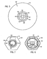
- Fig. 5 shows an end view of neck portion 102 of gas cylinder 48.
- Valve 110 is disposed in opening 108 of gas cylinder 48 and includes an actuator 142 generally centrally positioned therein. A plurality of ribs 144 are separated by a plurality of passages 146 and support actuator 142 in valve 110. Although biased closed, applying pressure to actuator 142 opens valve 110 and allows passage of shielding gas from within gas cylinder 48 through passages 146 and out of the gas cylinder.
- Threaded section 104 extends about valve 110 and has an axis of engagement generally coaxial with the axis of operation of actuator 142.
- Fig. 6 shows an end view of first end 106 of adapter 54.
- a plurality of threads 148 extends about periphery 116 of recess 114.
- Nipple 118 extends into recess 114 and is generally concentric with threads 148.
- Passage 120 is offset from nipple 118 and passes through adapter 54 to second end 122 of adapter 54 as shown in Fig. 7 .
- a threaded opening 150 extends into adapter 54 and is in fluid communication with passage 120. Threaded opening 150 is constructed to receive a pressure gauge therein. Such a construction allows pressure gauge 124, shown in Fig. 4 , to indicate the shielding gas pressure within passage 120.
- An annular groove 152 is formed about nipple 118 and provides for unobstructed passage of shielding gas from gas cylinder 48 to passage 120 upon connection of the gas cylinder to adapter 54.
- nipple 118 engages actuator 142 of valve 110 and immediately, automatically opens valve 110.
- a recess 153 is formed in second end 122 of adapter 54.
- Threaded portion 126 extends about a perimeter 156 of second end 122 and is constructed to threadingly engage regulator 56.
- Passage 120 fluidly communicates shielding gas to recess 154 which fluidly communicates shielding gas to regulator 56.
- Regulator 56 is shown in greater detail in Fig. 8 .
- Opening 128 is constructed to receive a filter element 158 therein.
- Filter element 158 prevents the penetration of particulates that may be carried on the shielding gas flow through adapter 54 from passing into regulator 56.
- Outlet 130 has a threaded portion 160 opposite ribbed portion 140 constructed to threadingly engage elbow portion 132 of outlet 130.
- Elbow portion 132 includes a threaded portion 162 constructed to threadingly engage regulator 56.
- Adjusting screw 136 is rotatably connected to a body 164 of regulator 56 and allows operator control over an amount of shielding gas allowed to flow through regulator 56.
- a relief valve opening 166 is formed in regulator 56 and is constructed to receive a relief valve assembly 138 therein.
- a spring 170 biases a seat retainer 172 against a seat 174.
- a relief valve body 168 secures spring 170, seat retainer 172, and seat 174 within relief valve opening 166 of regulator 56.
- Relief valve assembly 138 allows for the pressure relief of shielding gas contained in regulator 56.
- an inner periphery 176 of opening 128 of regulator 56 threadingly engages threaded portion 126 of adapter 54 and fluidly communicates shielding gas to flow passage 135 of regulator 56 from passage 120 of adapter 54.
- Pressure gauge 124 is also fluidly connected to passage 120 of adapter 54 and indicates the gas pressure therein.
- Threading 148 of periphery 116 of recess 114 of first end 106 of adapter 54 is threadingly connected to threaded section 104 of gas cylinder 48. When fully connected, end face 112 of neck portion 102 of gas cylinder 48 extends past an end 178 of nipple 118.
- nipple 118 engages actuator 142 of valve 110 of gas cylinder 48 and fluidly connects cavity 111 of gas cylinder 48 with passage 120 of adapter 54.
- nipple 118 displaces actuator 142 of valve 110 in a direction generally opposite the direction of engagement, indicated by arrow 180, of threaded section 104 of gas cylinder 48 and recess 114 of adapter 54 thereby opening valve 110.
- a spring 182 biases valve 110 to a closed position when actuator 142 is not biased by nipple 118 of adapter 54.
- the present invention includes a gas cylinder assembly for use in a welding-type device that has a gas cylinder configured to be enclosed in a welding-type device.
- the gas cylinder has a neck portion, a base portion and a body portion enclosing a cavity and constructed to receive a gas therein.
- a valve is disposed about the neck portion and operatively separates the cavity from atmosphere. The valve is operably engageable by a regulator constructed to allow flow of the gas therethrough.
- an adapter for a shielding gas system of a welding-type device has a passage extending through a body and fluidly connects a first end and a second end.
- the first end is constructed to be connected to a gas cylinder and the second end is constructed to be connected to a regulator with the body extending between the first and second ends.
- a nipple extends from the body into a recess formed in the first end and is constructed to operatively engage a valve of the gas cylinder.
- An alternate embodiment of the present invention has a shielding gas system for a welding-type device.
- the shielding gas system has a valve connected to a gas cylinder and biased to a closed position.
- a coupler is constructed to bias the valve open when the coupler is connected to the gas cylinder.
- Another embodiment of the present invention includes a shielding gas system for a welding device having a gas bottle with a first end having an opening and a second closed end. A body extends from the first end to the second closed end and a valve is disposed in the opening of the first end.
- the shielding gas system includes an adapter constructed to automatically open the valve when connected about the first end.
- a further embodiment of the present invention has a welding device having a housing enclosing a power source constructed to supply a welding power.
- a gas cylinder is attached to the housing and constructed to provide a shielding gas.
- the gas cylinder has a length that is less than a length of a side of the housing.
- Another embodiment of the present invention includes a method of providing shielding gas to a weld includes initiating a welding arc and opening a shielding gas path to a gas system and providing shielding gas immediately upon connection of a gas source to a welding-type device.
- An additional embodiment of the present invention includes a welding-type device having means for generating a welding power and means for providing shielding gas to a weld.
- a means for fluidly connecting the means for providing shielding gas is included that communicates shielding gas to the means for generating welding power upon connection of the means for providing shielding gas to the means for generating welding power.
Landscapes
- Engineering & Computer Science (AREA)
- Physics & Mathematics (AREA)
- Plasma & Fusion (AREA)
- Mechanical Engineering (AREA)
- Arc Welding In General (AREA)
- Filling Or Discharging Of Gas Storage Vessels (AREA)
- Unwinding Of Filamentary Materials (AREA)
Claims (8)
- Gaszylinderanordnung eines kofferartigen Schweißgerätes (10), umfassend:einen Gaszylinder (48) mit (a) einen Halsabschnitt (102), (b) einem Basisabschnitt (100), und (c) einem Körperabschnitt (98), der einen Hohlraum (111) umschließt und zum Aufnehmen eines Abschirmgases darin ausgebildet ist, wobei der Gaszylinder ausgebildet ist, um genau in einen ersten Abschnitt (50) einer Vertiefung (51) einzugreifen, die in einer Ummantelung (34) aus einem Gehäuse des Schweißgerätes (10) ausgebildet ist, wenn der Gaszylinder (48) von dem Schweißgerät umschlossen wird;einen Regler (56), der ausgebildet ist, um in dem Schweißgerät (10) enthalten zu sein;einen Adapter (54), der zwischen dem Regler (56) und dem Gaszylinder (48) angeordnet ist, wobei der Adapter (54) eine Vertiefung (114) aufweist, die in einem ersten Ende (106) ausgebildet ist; undein Ventil (110), das um den Halsabschnitt (102) angeordnet ist und den Hohlraum (111) von der Umgebungsluft betriebswirksam trennt, wobei das Ventil (110) von dem Regler (56), der dazu ausgebildet ist, dass ein Gas dadurch strömt, betriebswirksam in Eingriff gebracht werden kann,wobei der Umfang (116) der Vertiefung (114) des Adapters (54) mit einem Gewinde versehen ist, um in einen Gewindeabschnitt (104) des Gaszylinders (48) einzugreifen, wobei sich ein Nippel (118) in die Vertiefung (114) des ersten Endes (106) des Adapters (54) erstreckt und zum Eingreifen in das Ventil (110) des Gaszylinders (48) nach Verbinden des Gaszylinders mit dem Adapter ausgebildet ist, wodurch das Ventil (110) automatisch öffnet, wenn es mit dem Halsabschnitt (102) des Gaszylinders (48) verbunden wird; undwobei eine Einstellschraube (136) drehbar mit einem Körper (164) des Reglers (56) verbunden ist und einen Gasdurchgang, der sich zwischen einer Öffnung und dem Ausgang des Reglers (56) erstreckt, unterbricht, wodurch ein Bediener eine Menge von Gas, das durch den Regler (56) strömen darf, steuern kann.
- Gaszylinderanordnung nach Anspruch 1, wobei der Gaszylinder (48) entsorgt werden kann.
- Gaszylinderanordnung nach Anspruch 1, wobei der Gaszylinder (48) wieder auffüllbar ist.
- Gaszylinderanordnung nach Anspruch 1, wobei der Adapter (54) ferner ein erstes Ende (106), das mit dem Halsabschnitt (102) des Gaszylinders (48) verschraubt ist, und ein zweites Ende (122), das mit dem Regler (56) verschraubt ist, umfasst.
- Gaszylinderanordnung nach Anspruch 1, wobei der Adapter (54) einen ununterbrochenen Durchgang (120) dadurch aufweist.
- Gaszylinderanordnung nach Anspruch 1, wobei der Adapter (54) eine erste Öffnung (114) aufweist, die zum Eingreifen in den Gaszylinder (48) ausgebildet ist, eine zweite Öffnung (126), die zum Eingreifen in den Regler (56) ausgebildet ist, und eine dritte Öffnung (150), die zum Eingreifen in einen Druckmesser (124) ausgelegt ist, aufweist.
- Gaszylinderanordnung nach Anspruch 1, wobei der Regler (56) ferner ein bidirektionales Ventil umfasst, das in Fluidverbindung mit einem anderen Gaszylinder ausgebildet ist.
- Gaszylinderanordnung nach Anspruch 1, ferner umfassend einen Druckmesser (124), der zwischen dem Ventil (110) und dem Regler (56) verbunden ist.
Applications Claiming Priority (2)
| Application Number | Priority Date | Filing Date | Title |
|---|---|---|---|
| US10/709,540 US7411147B2 (en) | 2004-05-12 | 2004-05-12 | Gas bottle for welding-type devices |
| US709540 | 2004-05-12 |
Publications (3)
| Publication Number | Publication Date |
|---|---|
| EP1596123A2 EP1596123A2 (de) | 2005-11-16 |
| EP1596123A3 EP1596123A3 (de) | 2011-04-27 |
| EP1596123B1 true EP1596123B1 (de) | 2015-07-29 |
Family
ID=34935355
Family Applications (1)
| Application Number | Title | Priority Date | Filing Date |
|---|---|---|---|
| EP05008477.1A Expired - Fee Related EP1596123B1 (de) | 2004-05-12 | 2005-04-19 | Gasflasche für Schweißgeräte |
Country Status (5)
| Country | Link |
|---|---|
| US (2) | US7411147B2 (de) |
| EP (1) | EP1596123B1 (de) |
| JP (1) | JP2005324252A (de) |
| CA (1) | CA2504424C (de) |
| MX (1) | MXPA05005006A (de) |
Families Citing this family (15)
| Publication number | Priority date | Publication date | Assignee | Title |
|---|---|---|---|---|
| US7763824B2 (en) * | 2006-04-04 | 2010-07-27 | Illinois Tool Works Inc. | Cable management system for plasma cutter |
| US8847116B2 (en) * | 2006-06-12 | 2014-09-30 | Victor Equipment Company | Wire feeder with interchangeable adaptor cartridges |
| US7615719B2 (en) | 2006-09-11 | 2009-11-10 | Hypertherm, Inc. | Autonomous plasma cutting system |
| US8350182B2 (en) * | 2006-09-11 | 2013-01-08 | Hypertherm, Inc. | Portable autonomous material processing system |
| US9399263B2 (en) * | 2007-08-31 | 2016-07-26 | Hobart Brothers Company | Portable battery powered welder |
| US8476555B2 (en) * | 2008-08-29 | 2013-07-02 | Illinois Tool Works Inc. | Portable welding wire feed system and method |
| US9522438B2 (en) | 2012-11-09 | 2016-12-20 | Hypertherm, Inc. | Battery-controlled plasma arc torch system |
| US9527153B2 (en) | 2013-03-14 | 2016-12-27 | Lincoln Global, Inc. | Camera and wire feed solution for orbital welder system |
| US9770775B2 (en) | 2013-11-11 | 2017-09-26 | Lincoln Global, Inc. | Orbital welding torch systems and methods with lead/lag angle stop |
| USD738944S1 (en) * | 2013-11-12 | 2015-09-15 | Lincoln Global, Inc. | On-board tool box for portable wire feeder |
| US9517524B2 (en) | 2013-11-12 | 2016-12-13 | Lincoln Global, Inc. | Welding wire spool support |
| US9550251B2 (en) | 2014-03-28 | 2017-01-24 | Hypertherm, Inc. | Power supply assembly for a plasma arc torch system |
| US10150173B2 (en) | 2014-11-07 | 2018-12-11 | Illinois Tool Works Inc. | Welding type power supply with wind tunnel |
| CA3039817A1 (en) | 2016-10-21 | 2018-04-26 | Hypertherm, Inc. | Plasma power tool |
| DE102020205319A1 (de) | 2020-04-27 | 2021-10-28 | Fronius International Gmbh | Vorrichtung und Verfahren zum Versorgen eines Schweißgerätes mit einem Schutzgas |
Citations (2)
| Publication number | Priority date | Publication date | Assignee | Title |
|---|---|---|---|---|
| GB2151752A (en) * | 1983-12-23 | 1985-07-24 | Taymar Ltd | Gas flow regulating assembly |
| US20070151606A1 (en) * | 2005-02-12 | 2007-07-05 | Felix Querejeta | Dual gas pressure regulator for a household appliance |
Family Cites Families (29)
| Publication number | Priority date | Publication date | Assignee | Title |
|---|---|---|---|---|
| US3127072A (en) * | 1964-03-31 | Pressure container closure construc- | ||
| US2510205A (en) * | 1949-02-11 | 1950-06-06 | Linde Air Prod Co | Inert-gas shielded continuous-feed metal-arc welding apparatus |
| US3309497A (en) * | 1966-01-21 | 1967-03-14 | Milo M Kensrue | Welding back pack |
| US3731718A (en) | 1971-03-03 | 1973-05-08 | Springer Co | Adapter connector |
| IT1037752B (it) * | 1978-07-13 | 1979-11-20 | Rinaldi R | Gruppo portatile autonomo con cannello per produrre una fiamma a ossigeno e gas |
| DE8308999U1 (de) | 1983-03-25 | 1983-11-24 | European Mig Weldors A/S, 5580 Aaby | CO 2-Schweißgerät |
| JPS6064769A (ja) | 1983-09-21 | 1985-04-13 | Hitachi Ltd | 溶接装置 |
| US4702277A (en) | 1985-05-01 | 1987-10-27 | Veriflo Corporation | Cylinder valve-regulator |
| US4782204A (en) * | 1986-04-11 | 1988-11-01 | Eutectic Corporation | Adapter for control of gas flow to a gas-constricted arc nozzle or the like |
| US5591171A (en) | 1991-06-14 | 1997-01-07 | Brown; Byron L. | Adapter and method for measuring pressures of fluid materials |
| FR2689209B1 (fr) * | 1992-03-31 | 1997-01-10 | Air Liquide | Ensemble d'alimentation en gaz industriel d'un appareil utilisateur portable. |
| DE4330157C1 (de) * | 1993-09-07 | 1995-04-13 | Geesthacht Gkss Forschung | Vorrichtung zum elektrischen Schweißen mittels zugeführten Schweißzusatzwerkstoffs in einer nassen Umgebung |
| US5507531A (en) | 1995-05-04 | 1996-04-16 | Ewal Manufacturing Company, Inc. | Seal enhancer for cylinder valve connection |
| US5791328A (en) | 1997-02-24 | 1998-08-11 | Alexander; Aaron K. | Air valve for marking pellet gun |
| US6213111B1 (en) | 1997-06-25 | 2001-04-10 | Aaron K. Alexander | Gas holding chamber for air-powered paintball guns |
| US5904133A (en) | 1997-06-25 | 1999-05-18 | Alexander; Aaron K. | Paintball gun air reservoir |
| DE19727847C2 (de) | 1997-06-26 | 2001-05-10 | Auergesellschaft Gmbh | Verschluß für Druckgasflaschen |
| US5950611A (en) | 1997-12-15 | 1999-09-14 | Lx3 Corporation | Paintball gun having movable compressed gas tank |
| US6474325B2 (en) | 1999-01-22 | 2002-11-05 | Npf Limited | Gas regulator |
| US6060690A (en) * | 1999-06-24 | 2000-05-09 | Caterpillar Inc. | Welding nozzle for improved gas coverage |
| US6229447B1 (en) * | 2000-02-09 | 2001-05-08 | C. Gene Hand | Indicator assembly for a pressurized gas line |
| US6405722B2 (en) | 2000-03-09 | 2002-06-18 | Daniel H. Colby | Single stage regulator and method for regulating compressed air therefor |
| US6543475B2 (en) | 2000-04-27 | 2003-04-08 | Daniel H. Colby | Pneumatic valve and regulator apparatus and method for regulating compressed air therefor |
| US6343599B1 (en) | 2000-07-26 | 2002-02-05 | Aldo Perrone | Paintball gun with pulse valve firing mechanism |
| US6479795B1 (en) * | 2000-10-11 | 2002-11-12 | Illinois Tool Works Inc. | Portable welding wire feeder and housing |
| US6644295B2 (en) | 2001-07-03 | 2003-11-11 | Smart Parts, Inc. | Pneumatic assembly for a paintball gun |
| US6675791B1 (en) | 2002-01-17 | 2004-01-13 | Akalmp, Inc. | Pressure regulator for pneumatic guns |
| US6590184B1 (en) * | 2002-05-15 | 2003-07-08 | Illinois Tool Works Inc. | Rack assembly support for welding machine |
| US6977358B2 (en) | 2003-07-02 | 2005-12-20 | Illinois Tool Works Inc. | Welder with integrated gas bottle |
-
2004
- 2004-05-12 US US10/709,540 patent/US7411147B2/en active Active
-
2005
- 2005-04-12 CA CA2504424A patent/CA2504424C/en not_active Expired - Fee Related
- 2005-04-19 EP EP05008477.1A patent/EP1596123B1/de not_active Expired - Fee Related
- 2005-05-10 MX MXPA05005006A patent/MXPA05005006A/es active IP Right Grant
- 2005-05-10 JP JP2005137122A patent/JP2005324252A/ja active Pending
-
2007
- 2007-05-31 US US11/756,512 patent/US20070221628A1/en not_active Abandoned
Patent Citations (2)
| Publication number | Priority date | Publication date | Assignee | Title |
|---|---|---|---|---|
| GB2151752A (en) * | 1983-12-23 | 1985-07-24 | Taymar Ltd | Gas flow regulating assembly |
| US20070151606A1 (en) * | 2005-02-12 | 2007-07-05 | Felix Querejeta | Dual gas pressure regulator for a household appliance |
Also Published As
| Publication number | Publication date |
|---|---|
| JP2005324252A (ja) | 2005-11-24 |
| CA2504424A1 (en) | 2005-11-12 |
| US20050252889A1 (en) | 2005-11-17 |
| US20070221628A1 (en) | 2007-09-27 |
| CA2504424C (en) | 2011-03-29 |
| MXPA05005006A (es) | 2005-11-17 |
| EP1596123A2 (de) | 2005-11-16 |
| EP1596123A3 (de) | 2011-04-27 |
| US7411147B2 (en) | 2008-08-12 |
Similar Documents
| Publication | Publication Date | Title |
|---|---|---|
| EP1596123B1 (de) | Gasflasche für Schweißgeräte | |
| US7423238B2 (en) | Gas system for wire feeding devices | |
| AU2006213505B2 (en) | Gas system for welding-type devices | |
| US7985940B2 (en) | Welder with internal shielding gas regulator | |
| US6977358B2 (en) | Welder with integrated gas bottle | |
| US8278601B2 (en) | Spool gun having unitary shielding gas and weld power connector | |
| US20080223830A1 (en) | Shielding gas cylinder holder for welding-type devices | |
| US9803572B2 (en) | Systems and methods for controlling fuel vapor flow in an engine-driven generator | |
| EP3303814B1 (de) | Vorrichtung und verfahren zur regelung von kraftstoffdampffluss in einem motorgetriebenen generator |
Legal Events
| Date | Code | Title | Description |
|---|---|---|---|
| PUAI | Public reference made under article 153(3) epc to a published international application that has entered the european phase |
Free format text: ORIGINAL CODE: 0009012 |
|
| 17P | Request for examination filed |
Effective date: 20050419 |
|
| AK | Designated contracting states |
Kind code of ref document: A2 Designated state(s): AT BE BG CH CY CZ DE DK EE ES FI FR GB GR HU IE IS IT LI LT LU MC NL PL PT RO SE SI SK TR |
|
| AX | Request for extension of the european patent |
Extension state: AL BA HR LV MK YU |
|
| PUAL | Search report despatched |
Free format text: ORIGINAL CODE: 0009013 |
|
| AK | Designated contracting states |
Kind code of ref document: A3 Designated state(s): AT BE BG CH CY CZ DE DK EE ES FI FR GB GR HU IE IS IT LI LT LU MC NL PL PT RO SE SI SK TR |
|
| AX | Request for extension of the european patent |
Extension state: AL BA HR LV MK YU |
|
| RIC1 | Information provided on ipc code assigned before grant |
Ipc: B23K 9/32 20060101ALI20110324BHEP Ipc: F17C 13/04 20060101AFI20050826BHEP Ipc: F16L 29/02 20060101ALI20110324BHEP |
|
| 17Q | First examination report despatched |
Effective date: 20110816 |
|
| AKX | Designation fees paid |
Designated state(s): AT DE FR GB IT |
|
| RAP1 | Party data changed (applicant data changed or rights of an application transferred) |
Owner name: ILLINOIS TOOL WORKS INC. |
|
| GRAP | Despatch of communication of intention to grant a patent |
Free format text: ORIGINAL CODE: EPIDOSNIGR1 |
|
| INTG | Intention to grant announced |
Effective date: 20150317 |
|
| GRAS | Grant fee paid |
Free format text: ORIGINAL CODE: EPIDOSNIGR3 |
|
| GRAA | (expected) grant |
Free format text: ORIGINAL CODE: 0009210 |
|
| AK | Designated contracting states |
Kind code of ref document: B1 Designated state(s): AT DE FR GB IT |
|
| REG | Reference to a national code |
Ref country code: GB Ref legal event code: FG4D |
|
| REG | Reference to a national code |
Ref country code: AT Ref legal event code: REF Ref document number: 739610 Country of ref document: AT Kind code of ref document: T Effective date: 20150815 |
|
| REG | Reference to a national code |
Ref country code: DE Ref legal event code: R096 Ref document number: 602005047082 Country of ref document: DE |
|
| REG | Reference to a national code |
Ref country code: AT Ref legal event code: MK05 Ref document number: 739610 Country of ref document: AT Kind code of ref document: T Effective date: 20150729 |
|
| PG25 | Lapsed in a contracting state [announced via postgrant information from national office to epo] |
Ref country code: AT Free format text: LAPSE BECAUSE OF FAILURE TO SUBMIT A TRANSLATION OF THE DESCRIPTION OR TO PAY THE FEE WITHIN THE PRESCRIBED TIME-LIMIT Effective date: 20150729 |
|
| PG25 | Lapsed in a contracting state [announced via postgrant information from national office to epo] |
Ref country code: IT Free format text: LAPSE BECAUSE OF FAILURE TO SUBMIT A TRANSLATION OF THE DESCRIPTION OR TO PAY THE FEE WITHIN THE PRESCRIBED TIME-LIMIT Effective date: 20150729 |
|
| REG | Reference to a national code |
Ref country code: DE Ref legal event code: R097 Ref document number: 602005047082 Country of ref document: DE |
|
| PLBE | No opposition filed within time limit |
Free format text: ORIGINAL CODE: 0009261 |
|
| STAA | Information on the status of an ep patent application or granted ep patent |
Free format text: STATUS: NO OPPOSITION FILED WITHIN TIME LIMIT |
|
| 26N | No opposition filed |
Effective date: 20160502 |
|
| REG | Reference to a national code |
Ref country code: DE Ref legal event code: R119 Ref document number: 602005047082 Country of ref document: DE |
|
| GBPC | Gb: european patent ceased through non-payment of renewal fee |
Effective date: 20160419 |
|
| REG | Reference to a national code |
Ref country code: FR Ref legal event code: ST Effective date: 20161230 |
|
| PG25 | Lapsed in a contracting state [announced via postgrant information from national office to epo] |
Ref country code: FR Free format text: LAPSE BECAUSE OF NON-PAYMENT OF DUE FEES Effective date: 20160502 Ref country code: GB Free format text: LAPSE BECAUSE OF NON-PAYMENT OF DUE FEES Effective date: 20160419 Ref country code: DE Free format text: LAPSE BECAUSE OF NON-PAYMENT OF DUE FEES Effective date: 20161101 |