EP1595967B1 - Alloy steel powder for metal injection molding improved in sintering characteristics and sintered article - Google Patents
Alloy steel powder for metal injection molding improved in sintering characteristics and sintered article Download PDFInfo
- Publication number
- EP1595967B1 EP1595967B1 EP04709727.4A EP04709727A EP1595967B1 EP 1595967 B1 EP1595967 B1 EP 1595967B1 EP 04709727 A EP04709727 A EP 04709727A EP 1595967 B1 EP1595967 B1 EP 1595967B1
- Authority
- EP
- European Patent Office
- Prior art keywords
- sintering
- injection molding
- metal injection
- amount
- powder
- Prior art date
- Legal status (The legal status is an assumption and is not a legal conclusion. Google has not performed a legal analysis and makes no representation as to the accuracy of the status listed.)
- Expired - Lifetime
Links
Images




Classifications
-
- C—CHEMISTRY; METALLURGY
- C22—METALLURGY; FERROUS OR NON-FERROUS ALLOYS; TREATMENT OF ALLOYS OR NON-FERROUS METALS
- C22C—ALLOYS
- C22C38/00—Ferrous alloys, e.g. steel alloys
- C22C38/04—Ferrous alloys, e.g. steel alloys containing manganese
-
- B—PERFORMING OPERATIONS; TRANSPORTING
- B22—CASTING; POWDER METALLURGY
- B22F—WORKING METALLIC POWDER; MANUFACTURE OF ARTICLES FROM METALLIC POWDER; MAKING METALLIC POWDER; APPARATUS OR DEVICES SPECIALLY ADAPTED FOR METALLIC POWDER
- B22F3/00—Manufacture of workpieces or articles from metallic powder characterised by the manner of compacting or sintering; Apparatus specially adapted therefor ; Presses and furnaces
- B22F3/22—Manufacture of workpieces or articles from metallic powder characterised by the manner of compacting or sintering; Apparatus specially adapted therefor ; Presses and furnaces for producing castings from a slip
- B22F3/225—Manufacture of workpieces or articles from metallic powder characterised by the manner of compacting or sintering; Apparatus specially adapted therefor ; Presses and furnaces for producing castings from a slip by injection molding
-
- C—CHEMISTRY; METALLURGY
- C22—METALLURGY; FERROUS OR NON-FERROUS ALLOYS; TREATMENT OF ALLOYS OR NON-FERROUS METALS
- C22C—ALLOYS
- C22C33/00—Making ferrous alloys
- C22C33/02—Making ferrous alloys by powder metallurgy
- C22C33/0257—Making ferrous alloys by powder metallurgy characterised by the range of the alloying elements
- C22C33/0278—Making ferrous alloys by powder metallurgy characterised by the range of the alloying elements with at least one alloying element having a minimum content above 5%
- C22C33/0285—Making ferrous alloys by powder metallurgy characterised by the range of the alloying elements with at least one alloying element having a minimum content above 5% with Cr, Co, or Ni having a minimum content higher than 5%
-
- C—CHEMISTRY; METALLURGY
- C22—METALLURGY; FERROUS OR NON-FERROUS ALLOYS; TREATMENT OF ALLOYS OR NON-FERROUS METALS
- C22C—ALLOYS
- C22C38/00—Ferrous alloys, e.g. steel alloys
- C22C38/02—Ferrous alloys, e.g. steel alloys containing silicon
-
- C—CHEMISTRY; METALLURGY
- C22—METALLURGY; FERROUS OR NON-FERROUS ALLOYS; TREATMENT OF ALLOYS OR NON-FERROUS METALS
- C22C—ALLOYS
- C22C38/00—Ferrous alloys, e.g. steel alloys
- C22C38/18—Ferrous alloys, e.g. steel alloys containing chromium
- C22C38/22—Ferrous alloys, e.g. steel alloys containing chromium with molybdenum or tungsten
-
- C—CHEMISTRY; METALLURGY
- C22—METALLURGY; FERROUS OR NON-FERROUS ALLOYS; TREATMENT OF ALLOYS OR NON-FERROUS METALS
- C22C—ALLOYS
- C22C38/00—Ferrous alloys, e.g. steel alloys
- C22C38/18—Ferrous alloys, e.g. steel alloys containing chromium
- C22C38/26—Ferrous alloys, e.g. steel alloys containing chromium with niobium or tantalum
-
- B—PERFORMING OPERATIONS; TRANSPORTING
- B22—CASTING; POWDER METALLURGY
- B22F—WORKING METALLIC POWDER; MANUFACTURE OF ARTICLES FROM METALLIC POWDER; MAKING METALLIC POWDER; APPARATUS OR DEVICES SPECIALLY ADAPTED FOR METALLIC POWDER
- B22F2998/00—Supplementary information concerning processes or compositions relating to powder metallurgy
Definitions
- the present invention relates to an alloyed steel powder for metal injection molding (MIM) which is effective to realize complex-shaped parts of very hard, highly corrosion resistant martensite stainless steel or tools of alloyed steel with good dimensional precision, and relates to a sintered body.
- MIM metal injection molding
- SKD11, SUS420, SUS440C and the like have conventionally been used as metal injection molding powders for obtaining very hard, highly corrosion resistant sintered bodies.
- These steels in which hardness is obtained by mainly use of Cr carbide exhibit an austenite phase in the sintering temperature range, and have a poor degree of sintering because the speed of elemental movement (diffusion) which promotes sintering is slower than in a ferrite phase.
- US 4,917,961 describes a method of producing a corrosion-, heat- and wear-resistant member which comprises packing an atomized powder of a high-carbon high-chromium steel into a capsule, heating the capsule packed with the powder, then extruding the capsule packed with the powder to obtain a stock not containing carbide grains greater than 3 ⁇ m, working the stock, polishing a surface of the stock, and evaporating a film of TiC and/or TiN onto the polished surface, and further a corrosion-, heat- and wear-resistant member produced by the method.
- the corrosion-, heat- and wear-resistant member according to US 4,917,961 is suitable for being member for tools used under extremely severe conditions, such as various tools for can manufacturing, molding tools used under extremely severe conditions, such as various tools for reinforced plastics, etc.
- the present invention has the following constitution.
- the focus of the present invention is on producing a Nb carbide with low diffusion by adding Nb to a steel alloyed primarily with Cr carbide. Because this Nb carbide has a low diffusion speed it is unlikely to bulk by diffusion during sintering of the metal injection molded product, and the Cr carbide is also precipitated around the core of this Nb carbide.
- C forms carbides and contributes hardness, resulting in a martensite structure.
- 0.1 to 1.8% is desirable as the amount range of C in the powder.
- the sintering temperature and sintered density vary according to the amount of C. Consequently, graphite is added appropriately during molding of the powder to adjust the amount of C in the sintered product to 0.1 to 1.7%.
- a sintered body with a high sintered density can be manufactured under easy temperature control.
- the lower limit of 0.1% in both powder and sintered body was set because that is the minimum amount necessary to produce the aforementioned Nb carbide and because it is the minimum amount at which the C would dissolve in the matrix to form martensite.
- Si improves deoxidation and hot water flow. If the amount is less than 0.3%, the oxygen amount rises and hot water flow is adversely affected, while if it is more than 1.2%, hardenability is adversely affected.
- Mn is less than 0.1%, hot water flow is adversely affected, while if it is over 0.5%, it combines with oxygen, increasing the amount of oxygen in the powder. Consequently, it is set in the range of 0.1 to 0.5%.
- Cr improves hardenability and increases hardness by producing carbides. It also dissolves in the matrix including the carbides, thereby, it improves corrosion resistance. A range of 11.0 to 18.0% is desirable.
- Mo, V and W produce carbides, and together with Nb have a pinning effect on the Cr carbides therefore they enhance the strength and hardness of the sintered body. If these are more than 5.0%, toughness will be diminished so 5.0% or less is desirable, and a range of 0.3 to 1.6% is more desirable from the standpoint of hardenability and cost-effectiveness. A noticeable improvement in hardness is difficult to achieve below 0.3%, while more than 1.6% is not cost-effective.
- Nb controls diffusion of Cr carbides and improves hardenability by means of the pinning effect of low-diffusion Nb carbides.
- By adding 2.0 to 5.0% Nb it is possible to improve the productivity of the sintering furnace because the sintering temperature needs only to be controlled within ⁇ 25°C rather than within ⁇ 5°C as it does conventionally. This effect isn't sufficient if the amount of Nb is less than 2.0%, while if it exceeds 5.0%, the amount of oxygen increases and moldability is adversely affected.
- Table 1 The samples shown in Table 1 below were prepared and their sintering characteristics tested.
- Table 1 Steel type Composition (%) Dm ( ⁇ m) T/D (g/cm 3 ) C Si Mn Cr Mo V W Nb O Fe SKD11 1.66 0.34 0.44 11.80 1.02 - - - 3300 Remainder 11.90 4.04 SUS420 0.27 0.85 0.33 13.09 0.59 - - - 3200 Remainder 10.01 4.30 SUS440C 0.96 0.91 0.18 17.12 0.05 0.07 - - 2700 Remainder 9.72 4.21 Comp.
- Example 1 0.60 0.73 0.47 12.53 1.49 - - 0.34 3900 Remainder 10.22 4.27
- Example 1 1.03 0.92 0.22 17.01 - - - 3.01 4100 Remainder 9.92 4.17
- Example 2 0.66 0.88 0.44 12.18 1.42 - - 3.22 4200 Remainder 10.98 4.18
- Example 3 0.96 0.87 0.21 17.12 0.41 0.17 0.08 2.99 3400 Remainder 9.86 4.08
- Example 4 0.56 0.93 0.31 12.34 0.50 - - 2.81 2500 Remainder 9.92 4.17 Comp.
- Example 2 0.65 0.89 0.45 12.15 1.46 - - 7.33 13500 Remainder 10.34 4.20
- the C amount of each sample was adjusted.
- Graphite powder was added with the aim of achieving C amounts after sintering of 1.30%, 1.50% and 1.70% for SKD11, 0.30%, 0.50%, 0.70% and 0.90% for SUS420, 1.30% for Example 1, 0.75%, 0.80%, 1.00% and 1.20% for SUS440C, 0.50%, 0.70% and 0.90% for Comparative Example 1 and Example 2, 1.30% for Example 3 and 0.90% for Example 4.
- a sintering test was not performed in the case of Comparative Example 2 because the amount of oxygen was too great at the powder stage.
- the sintering test was performed as follows.
- a suitable amount of graphite powder was added to each of the metal powders shown in Table 1, based on the target amount of C after sintering, 5.0 wt% of stearic acid (outer number) was added to the powder, and uniform kneading was performed with heating at 80°C.
- the kneaded products were cooled to room temperature, and the solidified pellets were pulverized.
- Tables 2 through 5 show the sintered density of each sample at different sintering temperatures and for different target amounts of carbon after sintering.
- the amounts of C, O and N in the sintered products of each sample are shown at the bottom of Tables 2 through 5, along with sintered hardness (Hv) in the case of Tables 4 and 5.
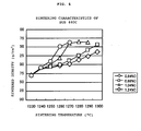
- the sintering characteristics shown in Tables 2 through 5 are also shown in graph form in Figures 2 through 9 .
- the structures were observed and the hardness of the sintered bodies was measured to determine the respective appropriate control ranges of sintering temperature.
- the appropriate control range of sintering temperature was the sintering temperature range within which the sintered density remained nearly constant within a range of ⁇ 0.1 g/cm 3 as the sintering temperature rose on the sintering temperature-sintered density graph.
- the appropriate sintering temperature control range is greater than in the case of SKD11, SUS420 and SUS440C. That is, while the appropriate sintering temperature control range is about 10°C in the case of SKD11, SUS420 and SUS440C, in the present invention it is broadened to about 50°C, facilitating sintering temperature control and improving productivity.
- the sensitivity to C value after sintering is also weaker, and almost the same sintering characteristics (temperature vs. density) are obtained with C values of 0.5 to 0.9%.
Landscapes
- Chemical & Material Sciences (AREA)
- Engineering & Computer Science (AREA)
- Mechanical Engineering (AREA)
- Materials Engineering (AREA)
- Metallurgy (AREA)
- Organic Chemistry (AREA)
- Manufacturing & Machinery (AREA)
- Powder Metallurgy (AREA)
Description
- The present invention relates to an alloyed steel powder for metal injection molding (MIM) which is effective to realize complex-shaped parts of very hard, highly corrosion resistant martensite stainless steel or tools of alloyed steel with good dimensional precision, and relates to a sintered body.
- SKD11, SUS420, SUS440C and the like have conventionally been used as metal injection molding powders for obtaining very hard, highly corrosion resistant sintered bodies. These steels in which hardness is obtained by mainly use of Cr carbide exhibit an austenite phase in the sintering temperature range, and have a poor degree of sintering because the speed of elemental movement (diffusion) which promotes sintering is slower than in a ferrite phase. On the other hand, if the temperature is raised to the temperature at which a liquid phase appears in order to promote sintering, a large amount of liquid phase arises at once, carbides are formed as networks at the grain boundaries, and either the strength of the product is seriously diminished or it is deformed to the point that the shape of the product cannot be maintained. To avoid these, it is necessary to proceed with the sintering temperature controlled within an extremely narrow temperature range of ±5°C or in other words about 10°C. Because of this, it has been necessary to limit the usable region of the sintering furnace, sacrificing productivity.
-
US 4,917,961 describes a method of producing a corrosion-, heat- and wear-resistant member which comprises packing an atomized powder of a high-carbon high-chromium steel into a capsule, heating the capsule packed with the powder, then extruding the capsule packed with the powder to obtain a stock not containing carbide grains greater than 3 µm, working the stock, polishing a surface of the stock, and evaporating a film of TiC and/or TiN onto the polished surface, and further a corrosion-, heat- and wear-resistant member produced by the method. The corrosion-, heat- and wear-resistant member according toUS 4,917,961 is suitable for being member for tools used under extremely severe conditions, such as various tools for can manufacturing, molding tools used under extremely severe conditions, such as various tools for reinforced plastics, etc. - It is an object of the present invention to eliminate the aforementioned diminishment of product strength and difficulty of controlling sintering temperature which are problems of the aforementioned conventional sintering alloys, and to provide an alloyed steel powder for metal injection molding and a sintered body which contribute to enhancing product characteristics and improving productivity of the sintering furnace.
- In order to solve the aforementioned problems, the present invention has the following constitution.
- (1) An alloyed steel powder for metal injection molding with improved degree of sintering, consisting as mass percentages of 0.1 to 1.8% C, 0.3 to 1.2% Si, 0.1 to 0.5% Mn, 11.0 to 18.0% Cr, 2.0 to 5.0% Nb optionally 0 to 5.0 % of at least one of Mo, V and W, and a remainder Fe and unavoidable impurities.
- (2) An alloyed steel powder for metal injection molding with improved degree of sintering according to (1) above, wherein the at least one of Mo, V and W is 0.3 to 1.6%.
- (3) An alloyed steel sintered body obtained by metal injection molding with improved degree of sintering, consisting as mass percentages of 0.1 to 1.7% C, 0.3 to 1.2% Si, 0.1 to 0.5% Mn, 11.0 to 18.0% Cr, 2.0 to 5.0% Nb optionally 0 to 5.0% of at least one of Mo, V and W, and a remainder Fe and unavoidable impurities.
- (4) An alloyed steel sintered body obtained by metal injection molding with improved degree of sintering according to (3) above, wherein the at least one of Mo, V and W is 0.3 to 1.6%.
- The focus of the present invention is on producing a Nb carbide with low diffusion by adding Nb to a steel alloyed primarily with Cr carbide. Because this Nb carbide has a low diffusion speed it is unlikely to bulk by diffusion during sintering of the metal injection molded product, and the Cr carbide is also precipitated around the core of this Nb carbide.
- Using the pinning effect of this Nb carbide it is possible to prevent from bulking and network formation of the carbide more effectively than when only the Cr carbide is present.
- In the constitution of the present invention, C forms carbides and contributes hardness, resulting in a martensite structure. 0.1 to 1.8% is desirable as the amount range of C in the powder. The sintering temperature and sintered density vary according to the amount of C. Consequently, graphite is added appropriately during molding of the powder to adjust the amount of C in the sintered product to 0.1 to 1.7%. A sintered body with a high sintered density can be manufactured under easy temperature control. The lower limit of 0.1% in both powder and sintered body was set because that is the minimum amount necessary to produce the aforementioned Nb carbide and because it is the minimum amount at which the C would dissolve in the matrix to form martensite. The upper limits of 1.8% in the powder and 1.7% in the sintered body were set considering the amount of C that is lost from the powder during sintering because at this level C contributes to hardness by forming a Cr carbide in the sintered body, but above 1.7% hardness is not further improved but on the contrary toughness (transverse rupture strength) is diminished.
- Si improves deoxidation and hot water flow. If the amount is less than 0.3%, the oxygen amount rises and hot water flow is adversely affected, while if it is more than 1.2%, hardenability is adversely affected.
- If Mn is less than 0.1%, hot water flow is adversely affected, while if it is over 0.5%, it combines with oxygen, increasing the amount of oxygen in the powder. Consequently, it is set in the range of 0.1 to 0.5%.
- Cr improves hardenability and increases hardness by producing carbides. It also dissolves in the matrix including the carbides, thereby, it improves corrosion resistance. A range of 11.0 to 18.0% is desirable.
- Mo, V and W produce carbides, and together with Nb have a pinning effect on the Cr carbides therefore they enhance the strength and hardness of the sintered body. If these are more than 5.0%, toughness will be diminished so 5.0% or less is desirable, and a range of 0.3 to 1.6% is more desirable from the standpoint of hardenability and cost-effectiveness. A noticeable improvement in hardness is difficult to achieve below 0.3%, while more than 1.6% is not cost-effective.
- Nb controls diffusion of Cr carbides and improves hardenability by means of the pinning effect of low-diffusion Nb carbides. By adding 2.0 to 5.0% Nb, it is possible to improve the productivity of the sintering furnace because the sintering temperature needs only to be controlled within ±25°C rather than within ±5°C as it does conventionally. This effect isn't sufficient if the amount of Nb is less than 2.0%, while if it exceeds 5.0%, the amount of oxygen increases and moldability is adversely affected.
-
-
Figure 1 shows a pattern of sintering performed in an example of the present invention. -
Figure 2 is a graph of the sintering characteristics of SKD11. -
Figure 3 is a graph of the sintering characteristics of SUS420. -
Figure 4 is a graph of the sintering characteristics of SUS440C. -
Figure 5 is a graph of the sintering characteristics of Comparative Example 1. -
Figure 6 is a graph of the sintering characteristics of Example 1 of the present invention. -
Figure 7 is a graph of the sintering characteristics of Example 2 of the present invention. -
Figure 8 is a graph of the sintering characteristics of Example 3 of the present invention. -
Figure 9 is a graph of the sintering characteristics of Example 4 of the present invention. - The samples shown in Table 1 below were prepared and their sintering characteristics tested.
Table 1 Steel type Composition (%) Dm (µm) T/D (g/cm3) C Si Mn Cr Mo V W Nb O Fe SKD11 1.66 0.34 0.44 11.80 1.02 - - - 3300 Remainder 11.90 4.04 SUS420 0.27 0.85 0.33 13.09 0.59 - - - 3200 Remainder 10.01 4.30 SUS440C 0.96 0.91 0.18 17.12 0.05 0.07 - - 2700 Remainder 9.72 4.21 Comp. Example 1 0.60 0.73 0.47 12.53 1.49 - - 0.34 3900 Remainder 10.22 4.27 Example 1 1.03 0.92 0.22 17.01 - - - 3.01 4100 Remainder 9.92 4.17 Example 2 0.66 0.88 0.44 12.18 1.42 - - 3.22 4200 Remainder 10.98 4.18 Example 3 0.96 0.87 0.21 17.12 0.41 0.17 0.08 2.99 3400 Remainder 9.86 4.08 Example 4 0.56 0.93 0.31 12.34 0.50 - - 2.81 2500 Remainder 9.92 4.17 Comp. Example 2 0.65 0.89 0.45 12.15 1.46 - - 7.33 13500 Remainder 10.34 4.20 - The C amount of each sample was adjusted. Graphite powder was added with the aim of achieving C amounts after sintering of 1.30%, 1.50% and 1.70% for SKD11, 0.30%, 0.50%, 0.70% and 0.90% for SUS420, 1.30% for Example 1, 0.75%, 0.80%, 1.00% and 1.20% for SUS440C, 0.50%, 0.70% and 0.90% for Comparative Example 1 and Example 2, 1.30% for Example 3 and 0.90% for Example 4. A sintering test was not performed in the case of Comparative Example 2 because the amount of oxygen was too great at the powder stage.
- The sintering test was performed as follows.
- A suitable amount of graphite powder was added to each of the metal powders shown in Table 1, based on the target amount of C after sintering, 5.0 wt% of stearic acid (outer number) was added to the powder, and uniform kneading was performed with heating at 80°C.
- The kneaded products were cooled to room temperature, and the solidified pellets were pulverized. The pulverized pellets were press molded at a molding pressure of 0.6 Ton/cm2 (φ11. 3 x 10t, N = 3).
- Sintering was performed according to the pattern shown in
Figure 1 . InFigure 1 , the sintering temperatures were the appropriate temperatures shown in Tables 2 through 5, such as 1370°C, 1390°C and 1410°C. - Tables 2 through 5 show the sintered density of each sample at different sintering temperatures and for different target amounts of carbon after sintering. The amounts of C, O and N in the sintered products of each sample are shown at the bottom of Tables 2 through 5, along with sintered hardness (Hv) in the case of Tables 4 and 5. The sintering characteristics shown in Tables 2 through 5 are also shown in graph form in
Figures 2 through 9 . - The structures were observed and the hardness of the sintered bodies was measured to determine the respective appropriate control ranges of sintering temperature. The appropriate control range of sintering temperature was the sintering temperature range within which the sintered density remained nearly constant within a range of ±0.1 g/cm3 as the sintering temperature rose on the sintering temperature-sintered density graph.
Table 2 Steel type SKD11 Steel type SUS420 Target C amount (%) after sintering Target C amount (%) after sintering 1.30 1.50 1.70 0.30 0.50 0.70 0.90 Molded product Density 4.91 4.90 4.88 Molded product density 4.85 4.81 4.78 4.76 Sintering Temperature(°C) 1220 - - 6.84 Sintering Temperature(°C) 1250 - - 6.75 7.07 1230 - 6.71 7.25 1270 - - 6.82 7.47 1240 6.81 7.20 7.61 1290 - - 7.06 7.78 1250 7.21 7.58 7.69 1310 6.82 - 7.38 7.91 1260 7.68 7.70 7.69 1330 6.84 6.98 7.79 - 1270 7.71 7.69 - 1350 6.86 7.27 7.85 - - - - - 1370 6.92 7.70 - - - - - - 1390 7.41 7.69 - - - - - - 1410 7.70 - - - C (%) 1.28 1.47 1.66 C (%) 0.33 0.57 0.79 0.99 O (ppm) 11 10 11 O (ppm) 17 40 27 41 N (ppm) 7 8 9 N (ppm) 3 4 1 3 Table 3 Steel type SUS440C Steel type Comparative Example 1 Target C amount(%) after sintering Target C amount (%) after sintering 0.75 0.80 1.00 1.20 0.50 0.70 0.90 Molded product density 5.01 5.00 4.96 4.94 Molded product density 4.68 4.69 4.69 Sintering temperature(°C) 1230 - - 6.72 6.70 Sintering temperature(°C) 1270 5.44 6.23 7.38 1240 6.88 6.91 6.88 6.93 1290 5.71 6.92 7.77 1250 6.93 6.94 7.00 7.10 1310 6.50 7.75 7.77 1260 6.97 7.00 7.19 7.52 1330 7.31 7.76 - 1270 7.03 7.12 7.61 7.63 1350 7.77 - - 1280 7.14 7.26 7.64 - 1370 7.77 - - 1290 7.24 7.41 7.63 - - - - - 1300 7.36 7.56 - - - - - - - - - - - - - - - C (%) 0.84 0.86 1.04 1.24 C (%) 0.54 0.76 0.96 O (ppm) 130 60 42 34 O (ppm) 21 14 20 N (ppm) 7 7 5 6 N (ppm) 3 2 13 Table 4 Steel type Example 1 Steel type Example 2 Target C amount (%) after sintering Target C amount (%) after sintering 1.30 0.50 0.70 0.90 Molded product density 4.41 Molded product density 4.56 4.55 4.56 Sintering temperature(°C) 1240 6.34 Sintering temperature(°C) 1290 5.88 6.12 6.44 1250 7.10 1310 6.79 6.98 7.27 1260 7.68 1330 7.76 7.76 7.76 1270 7.69 1350 7.76 7.75 7.75 1280 7.70 1370 7.77 7.76 7.77 1290 7.70 - - - - 1300 7.69 - - - - 1310 7.70 - - - - - - - - - - C (%) 1.25 C (%) 0.52 0.73 0.94 O (ppm) 11 O (ppm) 26 22 32 N (ppm) 7 N (ppm) 10 8 7 Sintered hardness (Hv) 700 Sintered hardness (Hv) 600 640 310 Table 5 Steel type Example 3 Steel type Example 4 Target C amount (%) after sintering Target C amount (%) after sintering 1.30 0.90 Molded product density 4.85 Molded product density 4.85 Sintering temperature (°C) 1230 - Sintering temperature (°C) 1300 6.84 1240 6.37 1310 7.25 1250 7.14 1320 7.58 1260 7.71 1330 7.83 1270 7.72 1340 7.83 1280 7.72 1350 7.83 1290 7.72 1360 7.79 1300 7.71 1370 7.77 1310 7.72 1380 7.75 C (%) 1.35 C (%) 0.94 O (ppm) 46 O (ppm) 11 N (ppm) 28 N (ppm) 9 Sintered hardness (Hv) 749 Sintered hardness (Hv) 680 - As discussed above, in the alloyed steel powder for metal injection molding of the present invention containing Nb, the appropriate sintering temperature control range is greater than in the case of SKD11, SUS420 and SUS440C. That is, while the appropriate sintering temperature control range is about 10°C in the case of SKD11, SUS420 and SUS440C, in the present invention it is broadened to about 50°C, facilitating sintering temperature control and improving productivity. The sensitivity to C value after sintering is also weaker, and almost the same sintering characteristics (temperature vs. density) are obtained with C values of 0.5 to 0.9%.
Claims (4)
- An alloyed steel powder for metal injection molding with improved degree of sintering, consisting as mass percentages of 0.1 to 1.8% C, 0.3 to 1.2% Si, 0.1 to 0.5% Mn, 11.0 to 18.0% Cr, 2.0 to 5.0% Nb, optionally 0 to 5.0% of at least one of Mo, V and W, and a remainder Fe and unavoidable impurities.
- An alloyed steel powder for metal injection molding with improved degree of sintering according to Claim 1, wherein the at least one of Mo, V and W is 0.3 to 1.6%.
- An alloyed steel sintered body obtained by metal injection molding with improved degree of sintering, consisting as mass percentages of 0.1 to 1.7% C, 0.3 to 1.2% Si, 0.1 to 0.5% Mn, 11.0 to 18.0% Cr, 2.0 to 5.0% Nb, optionally 0 to 5.0% of at least one of Mo, V and W, and a remainder Fe and unavoidable impurities.
- An alloyed steel sintered body obtained by metal injection molding with improved degree of sintering according to Claim 3, wherein the at least one of Mo, V and W is 0.3 to 1.6%.
Applications Claiming Priority (5)
| Application Number | Priority Date | Filing Date | Title |
|---|---|---|---|
| JP2003035619 | 2003-02-13 | ||
| JP2003035619 | 2003-02-13 | ||
| JP2003426678 | 2003-12-24 | ||
| JP2003426678A JP4849770B2 (en) | 2003-02-13 | 2003-12-24 | Alloy steel powder for metal injection molding with improved sinterability |
| PCT/JP2004/001422 WO2004072315A1 (en) | 2003-02-13 | 2004-02-10 | Alloy steel powder for metal injection molding improved in sintering characteristics and sintered article |
Publications (3)
| Publication Number | Publication Date |
|---|---|
| EP1595967A1 EP1595967A1 (en) | 2005-11-16 |
| EP1595967A4 EP1595967A4 (en) | 2008-12-03 |
| EP1595967B1 true EP1595967B1 (en) | 2015-01-07 |
Family
ID=32871179
Family Applications (1)
| Application Number | Title | Priority Date | Filing Date |
|---|---|---|---|
| EP04709727.4A Expired - Lifetime EP1595967B1 (en) | 2003-02-13 | 2004-02-10 | Alloy steel powder for metal injection molding improved in sintering characteristics and sintered article |
Country Status (7)
| Country | Link |
|---|---|
| US (1) | US7211125B2 (en) |
| EP (1) | EP1595967B1 (en) |
| JP (1) | JP4849770B2 (en) |
| KR (1) | KR100686426B1 (en) |
| CA (1) | CA2497920C (en) |
| TW (1) | TWI282373B (en) |
| WO (1) | WO2004072315A1 (en) |
Cited By (1)
| Publication number | Priority date | Publication date | Assignee | Title |
|---|---|---|---|---|
| EP3997252B1 (en) * | 2019-07-09 | 2025-10-29 | Oerlikon Metco (US) Inc. | Iron-based alloys designed for wear and corrosion resistance |
Families Citing this family (7)
| Publication number | Priority date | Publication date | Assignee | Title |
|---|---|---|---|---|
| KR100768700B1 (en) * | 2006-06-28 | 2007-10-19 | 학교법인 포항공과대학교 | Manufacturing method and alloy parts of alloy parts using metal injection molding |
| JP5344975B2 (en) * | 2009-04-13 | 2013-11-20 | 富士フイルム株式会社 | Recording tape cartridge |
| DE102010060487A1 (en) | 2010-11-11 | 2012-05-16 | Taiwan Powder Technologies Co., Ltd. | Steel powder used for forming sintered compact, comprises iron, carbon, silicon, manganese, chromium, titanium, copper and nickel, and solidifying agent |
| CN103008666A (en) * | 2012-12-27 | 2013-04-03 | 遵义中铂硬质合金有限责任公司 | Production technique for hard alloy cold heading die |
| CN104057093A (en) * | 2014-06-03 | 2014-09-24 | 宝得粉末注射成形(常熟)有限公司 | Processing method for needle bed |
| CN112041104B (en) * | 2018-05-23 | 2023-01-31 | 住友电工烧结合金株式会社 | Method for producing sintered member and sintered member |
| CN120776192B (en) * | 2025-07-16 | 2025-12-16 | 东北大学 | Metal injection molding 440C stainless steel and preparation method thereof |
Citations (1)
| Publication number | Priority date | Publication date | Assignee | Title |
|---|---|---|---|---|
| US4917961A (en) * | 1989-03-06 | 1990-04-17 | Sanyo Special Steel Co., Ltd. | Method of producing corrosion-, heat- and wear-resistant member, and the member produced |
Family Cites Families (22)
| Publication number | Priority date | Publication date | Assignee | Title |
|---|---|---|---|---|
| US2430671A (en) * | 1943-12-02 | 1947-11-11 | American Rolling Mill Co | Alloy process |
| JPS5822359A (en) * | 1981-07-30 | 1983-02-09 | Mitsubishi Metal Corp | Iron base sintered alloy for structural member of fuel supply apparatus |
| JPS5916952A (en) * | 1982-07-20 | 1984-01-28 | Mitsubishi Metal Corp | Fe-based sintered material excellent in wear resistance |
| JPS60135556A (en) * | 1983-12-23 | 1985-07-18 | Mitsubishi Metal Corp | Tip material joined to tip of stem of valve for internal- conbustion engine |
| JPS60215742A (en) * | 1984-04-10 | 1985-10-29 | Toyota Motor Corp | Special wear-resistant sintered alloy of high strength |
| JPS61174354A (en) * | 1985-01-28 | 1986-08-06 | Toyota Motor Corp | Manufacture of copper-containing sintered alloy excellent in high-temperature wear resistance |
| JPS62202045A (en) * | 1986-02-28 | 1987-09-05 | Toyota Motor Corp | Manufacture of sintered alloy superior in high temperature wear resistance |
| JPH01283340A (en) * | 1989-03-25 | 1989-11-14 | Daido Steel Co Ltd | Manufacturing method for high-density, high-strength sintered bodies |
| JPH0525591A (en) * | 1991-07-16 | 1993-02-02 | Hitachi Metals Ltd | Piston ring wire and manufacturing method thereof |
| JPH05171373A (en) * | 1991-12-24 | 1993-07-09 | Hitachi Metals Ltd | Powder high speed tool steel |
| US5449536A (en) * | 1992-12-18 | 1995-09-12 | United Technologies Corporation | Method for the application of coatings of oxide dispersion strengthened metals by laser powder injection |
| JPH06198713A (en) * | 1993-01-04 | 1994-07-19 | Hitachi Metals Ltd | Extrusion or injection molding screw and manufacturing method thereof |
| JP3555165B2 (en) | 1994-01-12 | 2004-08-18 | 大同特殊鋼株式会社 | Stainless steel powder for sintering |
| ES2140066T3 (en) * | 1995-03-10 | 2000-02-16 | Powdrex Ltd | STAINLESS STEEL POWDERS AND ARTICLES PRODUCED THEREOF BY POWDER METALLURGY. |
| JPH0971848A (en) * | 1995-09-01 | 1997-03-18 | Kubota Corp | High speed steel powder alloy with excellent corrosion resistance |
| JPH0953159A (en) * | 1995-12-25 | 1997-02-25 | Citizen Watch Co Ltd | Jewelry made of sintered body |
| SE9702299D0 (en) * | 1997-06-17 | 1997-06-17 | Hoeganaes Ab | Stainless steel powder |
| JPH11181501A (en) * | 1997-12-17 | 1999-07-06 | Injex:Kk | Method for producing metal powder and sintered body |
| SE520561C2 (en) * | 1998-02-04 | 2003-07-22 | Sandvik Ab | Process for preparing a dispersion curing alloy |
| DE19924515A1 (en) * | 1999-05-28 | 2000-11-30 | Edelstahl Witten Krefeld Gmbh | Spray-compacted steel, process for its production and composite material |
| SE0102102D0 (en) * | 2001-06-13 | 2001-06-13 | Hoeganaes Ab | High density stainless steel products and method of preparation thereof |
| JP4975916B2 (en) * | 2001-09-21 | 2012-07-11 | 株式会社日立製作所 | High toughness and high strength ferritic steel and its manufacturing method |
-
2003
- 2003-12-24 JP JP2003426678A patent/JP4849770B2/en not_active Expired - Lifetime
-
2004
- 2004-02-10 WO PCT/JP2004/001422 patent/WO2004072315A1/en not_active Ceased
- 2004-02-10 CA CA002497920A patent/CA2497920C/en not_active Expired - Lifetime
- 2004-02-10 US US10/527,900 patent/US7211125B2/en not_active Expired - Lifetime
- 2004-02-10 TW TW093103011A patent/TWI282373B/en not_active IP Right Cessation
- 2004-02-10 EP EP04709727.4A patent/EP1595967B1/en not_active Expired - Lifetime
- 2004-02-10 KR KR1020057008611A patent/KR100686426B1/en not_active Expired - Fee Related
Patent Citations (1)
| Publication number | Priority date | Publication date | Assignee | Title |
|---|---|---|---|---|
| US4917961A (en) * | 1989-03-06 | 1990-04-17 | Sanyo Special Steel Co., Ltd. | Method of producing corrosion-, heat- and wear-resistant member, and the member produced |
Cited By (1)
| Publication number | Priority date | Publication date | Assignee | Title |
|---|---|---|---|---|
| EP3997252B1 (en) * | 2019-07-09 | 2025-10-29 | Oerlikon Metco (US) Inc. | Iron-based alloys designed for wear and corrosion resistance |
Also Published As
| Publication number | Publication date |
|---|---|
| US7211125B2 (en) | 2007-05-01 |
| TWI282373B (en) | 2007-06-11 |
| EP1595967A4 (en) | 2008-12-03 |
| EP1595967A1 (en) | 2005-11-16 |
| KR20050072827A (en) | 2005-07-12 |
| WO2004072315A1 (en) | 2004-08-26 |
| TW200418998A (en) | 2004-10-01 |
| CA2497920A1 (en) | 2004-08-26 |
| JP2004263294A (en) | 2004-09-24 |
| US20060162494A1 (en) | 2006-07-27 |
| CA2497920C (en) | 2008-04-29 |
| JP4849770B2 (en) | 2012-01-11 |
| KR100686426B1 (en) | 2007-02-26 |
Similar Documents
| Publication | Publication Date | Title |
|---|---|---|
| US12577641B2 (en) | Wear resistant alloy | |
| EP2488675B1 (en) | Nitrogen containing, low nickel sintered stainless steel | |
| EP3692180B1 (en) | Stainless steel, a prealloyed powder obtained by atomizing the steel and use of the prealloyed powder | |
| CN111519113B (en) | High-strength stainless steel powder for electronic products and preparation process | |
| CN101792886B (en) | Steel for mold for plastic molding and mold for plastic molding | |
| EP3467128B9 (en) | Extrusion die made of hot working steel and production method thereof | |
| KR20120016660A (en) | High Strength Low Alloy Sintered Steel | |
| EP3034211A1 (en) | A wear resistant tool steel produced by HIP | |
| CN100402689C (en) | Steel molds for steel and plastic materials | |
| US4140527A (en) | Nitrogen containing powder metallurgical tool steel | |
| SE508872C2 (en) | Powder metallurgically made steel for tools, tools made therefrom, process for making steel and tools and use of steel | |
| US4121929A (en) | Nitrogen containing high speed steel obtained by powder metallurgical process | |
| EP3636791B1 (en) | Steel for mold | |
| EP1768803B1 (en) | Sintered part made of stainless steel powder | |
| EP0421811B1 (en) | Alloy steel for use in injection molded sinterings produced by powder metallurgy | |
| EP2551367B1 (en) | Prehardened steel for mold for plastic molding | |
| US7211125B2 (en) | Alloyed steel powder with improved degree of sintering for metal injection molding and sintered body | |
| US20090142219A1 (en) | Sinter-hardening powder and their sintered compacts | |
| EP3430179B1 (en) | A steel alloy and a tool | |
| US6200394B1 (en) | High speed tool steel | |
| US5976277A (en) | High speed tool steel, and manufacturing method therefor | |
| US20090142220A1 (en) | Sinter-hardening powder and their sintered compacts | |
| JPH0459362B2 (en) | ||
| SE539667C2 (en) | A wear resistant alloy | |
| GB1583777A (en) | Nitrogen-containing high-speed steel obtained by powder metallurgical process |
Legal Events
| Date | Code | Title | Description |
|---|---|---|---|
| PUAI | Public reference made under article 153(3) epc to a published international application that has entered the european phase |
Free format text: ORIGINAL CODE: 0009012 |
|
| 17P | Request for examination filed |
Effective date: 20050309 |
|
| AK | Designated contracting states |
Kind code of ref document: A1 Designated state(s): AT BE BG CH CY CZ DE DK EE ES FI FR GB GR HU IE IT LI LU MC NL PT RO SE SI SK TR |
|
| AX | Request for extension of the european patent |
Extension state: AL LT LV MK |
|
| DAX | Request for extension of the european patent (deleted) | ||
| RBV | Designated contracting states (corrected) |
Designated state(s): DE FR GB |
|
| A4 | Supplementary search report drawn up and despatched |
Effective date: 20081105 |
|
| 17Q | First examination report despatched |
Effective date: 20090728 |
|
| REG | Reference to a national code |
Ref country code: DE Ref legal event code: R079 Ref document number: 602004046458 Country of ref document: DE Free format text: PREVIOUS MAIN CLASS: C22C0038260000 Ipc: C22C0033020000 |
|
| GRAP | Despatch of communication of intention to grant a patent |
Free format text: ORIGINAL CODE: EPIDOSNIGR1 |
|
| RIC1 | Information provided on ipc code assigned before grant |
Ipc: C22C 38/22 20060101ALI20140930BHEP Ipc: C22C 38/02 20060101ALI20140930BHEP Ipc: C22C 33/02 20060101AFI20140930BHEP Ipc: C22C 38/04 20060101ALI20140930BHEP Ipc: C22C 38/26 20060101ALI20140930BHEP |
|
| INTG | Intention to grant announced |
Effective date: 20141022 |
|
| RIN1 | Information on inventor provided before grant (corrected) |
Inventor name: AIHARA, MICHITAKA, C/O RYOKOH CASTING CO., LTD. Inventor name: SODA, YUJI, C/O MITSUBISHI STEEL MFG. CO., LTD. |
|
| GRAS | Grant fee paid |
Free format text: ORIGINAL CODE: EPIDOSNIGR3 |
|
| GRAA | (expected) grant |
Free format text: ORIGINAL CODE: 0009210 |
|
| AK | Designated contracting states |
Kind code of ref document: B1 Designated state(s): DE FR GB |
|
| REG | Reference to a national code |
Ref country code: GB Ref legal event code: FG4D |
|
| REG | Reference to a national code |
Ref country code: DE Ref legal event code: R096 Ref document number: 602004046458 Country of ref document: DE Effective date: 20150226 |
|
| REG | Reference to a national code |
Ref country code: DE Ref legal event code: R097 Ref document number: 602004046458 Country of ref document: DE |
|
| PLBE | No opposition filed within time limit |
Free format text: ORIGINAL CODE: 0009261 |
|
| STAA | Information on the status of an ep patent application or granted ep patent |
Free format text: STATUS: NO OPPOSITION FILED WITHIN TIME LIMIT |
|
| 26N | No opposition filed |
Effective date: 20151008 |
|
| REG | Reference to a national code |
Ref country code: FR Ref legal event code: PLFP Year of fee payment: 13 |
|
| REG | Reference to a national code |
Ref country code: FR Ref legal event code: PLFP Year of fee payment: 14 |
|
| REG | Reference to a national code |
Ref country code: FR Ref legal event code: PLFP Year of fee payment: 15 |
|
| PGFP | Annual fee paid to national office [announced via postgrant information from national office to epo] |
Ref country code: FR Payment date: 20210113 Year of fee payment: 18 |
|
| PGFP | Annual fee paid to national office [announced via postgrant information from national office to epo] |
Ref country code: DE Payment date: 20210126 Year of fee payment: 18 Ref country code: GB Payment date: 20210203 Year of fee payment: 18 |
|
| REG | Reference to a national code |
Ref country code: DE Ref legal event code: R119 Ref document number: 602004046458 Country of ref document: DE |
|
| GBPC | Gb: european patent ceased through non-payment of renewal fee |
Effective date: 20220210 |
|
| PG25 | Lapsed in a contracting state [announced via postgrant information from national office to epo] |
Ref country code: FR Free format text: LAPSE BECAUSE OF NON-PAYMENT OF DUE FEES Effective date: 20220228 |
|
| PG25 | Lapsed in a contracting state [announced via postgrant information from national office to epo] |
Ref country code: GB Free format text: LAPSE BECAUSE OF NON-PAYMENT OF DUE FEES Effective date: 20220210 Ref country code: DE Free format text: LAPSE BECAUSE OF NON-PAYMENT OF DUE FEES Effective date: 20220901 |