TECHNICAL FIELD
Field of the Invention
The present invention relates to nickel-base alloys. Priority is claimed on
Japanese Patent Application No. 2003-44416, Japanese Patent Application No. 2003-44417
and Japanese Patent Application No. 2004-27444, the contents of which are
incorporated herein by reference.
BACKGROUND ART
Polymer electrolyte fuel cells which operate at low temperatures ranging from
room temperature to 80°C can be built to compact dimensions and thus are expected to be
used in automotive and portable fields. Development work on such fuel cells is
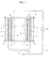
proceeding rapidly. FIG. 1 schematically shows the construction of such a polymer
electrolyte fuel cell, which includes hydrogen electrodes 1, oxygen electrodes 2, first
platinum catalysts 3 and second platinum catalysts 3', solid electrolyte membranes
(proton exchange membrane) 4, and unit cells 5. Each unit cell 5 has a solid electrolyte
membrane 4, on either side of which is provided a first platinum catalyst 3 and a second
platinum catalyst 3'. A hydrogen electrode I is provided outside of the first platinum
catalyst 3, and an oxygen electrode 2 is provided outside of the second platinum catalyst
3'. In order to stack these unit cells 5 together with intervening separators 6 to form the
polymer electrolyte fuel cell, a plurality of unit cells 5 are stacked with separators 6
therebetween by using at least two support plates 7 and fasteners 8 such as bolts and nuts.
Power generation principle within a unit cell 5 of the polymer electrolyte fuel cell
having this type of construction takes place as follows. Hydrogen obtained from natural
gas, methanol or the like is supplied to the hydrogen electrode 1, where the first platinum
catalyst 3 on the hydrogen electrode 1 side is used to decompose the hydrogen into
hydrogen ions and electrons. The electrons are led out as electricity to the exterior, flow
through an external load circuit (not shown), and reach the oxygen electrode 2. The
hydrogen ions pass through a solid electrolyte membrane 4 composed of a polymer
electrolyte -type ion-exchange membrane that allows only hydrogen ions to pass through,
and migrate to the oxygen electrode 2 side. On the oxygen electrode 2 side, the hydrogen
ions, electrons and oxygen react under the influence of the second platinum catalyst 3' to
form water. The role of the solid electrolyte membrane 4 is to allow hydrogen gas to pass
through as hydrogen ions, for which it needs to be wet. Because the hydrogen ions,
electrons and oxygen react to form water on the oxygen electrode 2 side, keeping the solid
electrolyte membrane 4 wet is not a problem. However, the hydrogen electrode 1 side
which is separated from the oxygen electrode 2 side by the solid electrolyte membrane 4
is not in this way supplied with water and thus ends up dry. Hence, to ensure the wetness
of the solid electrolyte membrane 4 on the hydrogen electrode 1 side, water 9 discharged
from the oxygen electrode 2 side is received by a manifold 10, passed through a pipe 11,
and supplied with the aid of a pump 12 to the solid electrolyte membrane 4 on the
hydrogen electrode 1 side.
As just described, the water 9 discharged from the oxygen electrode 2 side is
received by the manifold 10, passed through the pipe 11, and fed by means of a pump 12
to the solid electrolyte membrane 4 on the hydrogen electrode 1 side, thereby ensuring the
wetness of the solid electrolyte membrane 4 on the hydrogen electrode 1 side. However,
because the solid electrolyte membrane 4 used in polymer electrolyte fuel cells generally
has been administered sulfonation treatment, the water 9 discharged from the oxygen
electrode 2 side has sulfonic acid acidity and is thus mildly corrosive. Hence, there is a
need for the manifolds 10 and pipes 11 which receive water 9 to be corrosion resistant.
In some cases, the solid electrolyte membranes used in polymer electrolyte fuel
cells have been subjected to fluorination rather that sulfonation treatment. The water 9
discharged from the oxygen electrode 2 side will as a result have hydrofluoric acid
acidity. In such cases, there will similarly be a need for the manifolds 10 and pipes 11
which receive water 9 to be corrosion resistant.
In addition, throughholes (not shown) are provided in the hydrogen electrode I
and the oxygen electrode 2. The sulfonic acid acidic or hydrofluoric acid acidic water 9
that is discharged from the oxygen electrode 2 side passes through the throughholes (not
shown) and comes into contact with the separator 6. Moreover, the sulfonic acid acidic or
hydrofluoric acid acidic water 9 that is discharged from the oxygen electrode 2 side,
recirculated, and reaches the hydrogen electrode 1 side also passes through the
throughholes (not shown) and comes into contact with the separator 6. Hence, corrosion
resistance is required also of the separators 6.
These components such as manifolds 10, pipes 11 and separators 6 that require
corrosion resistance are generally made of a stainless steel such as SUS316L. In addition,
the sulfuric acid acidic or hydrofluoric acid acidic water produced on the oxygen
electrode 2 side disperses and settles on the support plates 7, fasteners 8 such as bolts and
nuts, and the like, corrode these as well. Therefore, stainless steels such as SUS316L are
also used in the support plates 7 and fasteners 8 such as bolts and nuts. That is, stainless
steels such as SUS316L are known to be used in the structural members, excluding unit
cells 5, for assembling polymer electrolyte fuel cells, such as support plates 7, fasteners 8,
manifolds 10, pipes 11 and separators 6 (collectively referred to hereinafter as "structural
members for polymer electrolyte fuel cells") (see, for example, JP-A No. 2001-6714, JP-A
No. 2000-299121, JP-A No. 2000-331696 and the like).
At a corrosion rate of less than 0.1 mm/year, structural members for polymer
electrolyte fuel cel ls are generally rated as "excellent" and the corrosion resistance of the
stainless steel is also generally rated as "excellent." However, a elution amount of metal
ions from stainless steel is large. Such metal ions that have leached from the stainless
steel degrade the solid electrolyte membrane, which can dramatically shorten the life of
the polymer electrolyte fuel cell. Accordingly, there has existed a desire for the
development of metal materials that undergo very little leaching of metal ions.
DISCLOSURE OF INVENTION
It is therefore an object of the present invention to provide a nickel-base alloy
which achieves very little elution amount of ions in the environment wherein the polymer
electrolyte fuel cell is formed. Another object of this invention is to provide structural
members for forming polymer electrolyte fuel cells, which structural members are
composed of a nickel-base alloy that undergoes very little leaching of ions in the polymer
electrolyte fuel cell environment wherein the environment is used when stacking unit
cells of the polymer electrolyte fuel cells for forming assembly.
As a result of extensive investigations conducted on ways of obtaining metal
materials that undergo very little leaching of metal ions in an environment for forming a
polymer electrolyte fuel cell, we have found that nickel-base alloys which include at least
29% but less than 42% (all percentages here and below are by weight) of chromium. The
nickel-base alloys include more than 1% and not more than 3% of tantalum, 0.001 to
0.05% magnesium, 0.001 to 0.04% nitrogen and 0.05 to 0.5% manganese, and
furthermore optionally may include one or more from among 0.1 to 2% molybdenum,
0.05 to 1.0% iron and 0.01 to 0.1% silicon. The balance of the nickel-base alloys are
nickel and unavoidable inadvertent impurities. The nickel-base alloys, which have a
composition wherein the carbon contained as inadvertent impurities is set to 0.05% or
less, have a corrosion rate of less than 0.1 mm/year in the environment for forming a
polymer electrolyte fuel cell. Furthermore, the nickel-base alloys achieve very little
leaching of ions in the environment for forming a polymer electrolyte fuel cell. We have
thus learned that these nickel-base alloys have effects, in structural members for forming
the polymer electrolyte fuel cells, that are even better than those of prior-art materials
such as stainless steels.
We have also discovered that nickel-base alloys which include at least 43% and
not more than 50% of chromium. The nickel-base alloys include 0. 1 to 2%
molybdenum, 0.001 to 0.05% magnesium, 0.001 to 0.04% nitrogen and 0.05 to 0.5%
manganese, and which optionally may include one or both 0.05 to 1.0% iron and 0.01 to
0.1% silicon. The balance of the nickel-base alloys is nickel and unavoidable inadvertent
impurities. The nickel-base alloys which moreover have a composition wherein the
carbon contained as inadvertent impurities is set to 0.05% or less have a corrosion rate of
less than 0.1 mm/year in the environment for forming a polymer electrolyte fuel cell. The
nickel-base alloys achieve very little leaching of ions in the environment for forming a
polymer electrolyte fuel cell. We have thus learned that these nickel-base alloy have
effects, in structural members for forming the polymer electrolyte fuel cells, that are even
better than those of prior-art materials such as stainless steels.
The first to sixth aspects of the invention are based on these findings.
In a first aspect, the invention provides:
BRIEF DESCRIPTION OF THE DIAGRAMS
FIG. 1 is a schematic view showing the construction of a polymer electrolyte fuel
cell.
BEST MODE FOR CARRYING OUT THE INVENTION
Limits for each element in the compositions of the nickel-base alloys according to
the first to fourth aspects which undergo very little leaching of ions in the environment
for forming a polymer electrolyte fuel cell are explained below in detail.
Chromium and Tantalum:
In an environment for forming a polymer electrolyte fuel cell containing a trace
amount of hydrofluoric acid, the presence of both chromium and tantalum dramatically
increases corrosion resistance. At least 29% chromium must be present in such cases.
However, the presence of 42% or more chromium, in combination with tantalum, makes
the formation of a single phase difficult to achieve and increases the amount of metal ions
that leach out, which is undesirable. Hence, the chromium content has been set to at least
29% but less than 42%. A chromium content of 35 to 41% is preferred.
Similarly, the tantalum content must be more than 1%. However, the presence of
more than 3% tantalum, in combination with chromium, compromises the phase stability
and increases the amount of metal ions that leach out, which is undesirable. Accordingly,
the tantalum content has been set to more than 1% and not more than 3%. A tantalum
content of at least 1.1 but less than 2.5% is preferred.
Nitrogen, Manganese and Magnesium:
The presence of nitrogen, manganese and magnesium serves to improve the phase
stability. That is, nitrogen, manganese and magnesium stabilize the Ni-fcc phase which is
the matrix, thus promoting the entry of chromium into a solid solution and discouraging
the deposition of a second phase. However, at a nitrogen content of less than 0.00 1 %,
there is no phase stabilizing effect. On the other hand, when more than 0.04% nitrogen is
present, nitrides form and the leaching of metal ions in the environment for forming a
polymer electrolyte fuel cell increases. Hence, the nitrogen content has been set at 0.001
to 0.04%, and preferably 0.005 to 0.03%.
Likewise, at a manganese content of less than 0.05%, there is no phase stabilizing
effect, whereas the presence of more than 0.5% increases the leaching of metal ions in an
environment for forming a polymer electrolyte fuel cell. Hence, the manganese content
has been set at 0.05 to 0.5%, and preferably 0.1 to 0.4%.
Similarly, at a magnesium content of less than 0.001%, there is no phase
stabilizing effect, whereas the presence of more than 0.05% increases the leaching of
metal ions in an environment for forming a polymer electrolyte fuel cell. Hence, the
magnesium content has been set at 0.001 to 0.05%, and preferably 0.002 to 0.04%.
Molybdenum:
Molybdenum has the effect in particular of suppressing an increase in the leaching
of metal ions when the sulfuric acid concentration rises within an environment for
forming a polymer electrolyte fuel cell containing a trace amount of sulfuric acid.
Molybdenum is thus added as an optional ingredient. It is effective at a concentration of
at least 0.1%, but if more than 2% is present, the phase stability deteriorates, discouraging
entry of the Cr-bcc phase into a solid solution. As a result, microcells form between the
Ni-fcc phase serving as the matrix and the Cr-bcc phase, which has the undesirable effect
of increasing the leaching of metal ions. Accordingly, the level of molybdenum included
in the nickel-base alloy of this invention has been set at 0.1 to 2%. A range of more than
0.1 but less than 0.5% is preferred.
Iron and Silicon:
Iron and silicon have strength-enhancing effects and are thus added as optional
ingredients. Iron is effective at a content of 0.05% or more, but when present at above
1%, the leaching of metal ions in an environment for forming a polymer electrolyte fuel
cell increases. Hence, the iron content has been set at 0.05 to 1%, and preferably at least
0.1% but less than 0.5%.
Similarly, silicon is effective at a content of 0.01% or more, but when present at
above 0.1%, the leaching of metal ions in an environment for forming a polymer
electrolyte fuel cell increases. Hence, the silicon content has been set at 0.01 to 0.1%, and
preferably 0.02 to 0.05%.
Carbon:
Carbon is present as an inadvertent impurity. The presence of a large amount of
carbon results in the formation of a carbide with chromium in the vicinity of crystal grain
boundaries, increasing the leaching of metal ions. Therefore, the lower the carbon
content the better. Hence, the upper limit in the carbon content present among
inadvertent impurities has been set at 0.05%. A carbon content of 0% is preferred. The
carbon content may be substantially from 0.001 to 0.05%.
Next, limits for each element in the compositions of the nickel-base alloys
according to the fifth and sixth aspects which undergo very little leaching of ions in the
environment for forming a polymer electrolyte fuel cell are explained below in detail.
Chromium:
In an environment for forming a polymer electrolyte fuel cell containing a trace
amount of sulfuric acid, chromium is effective for suppressing the leaching of metal ions.
In such cases, the presence of more than 43% is required, but machining becomes
difficult at a level of more than 50%. Accordingly, the chromium present in the nickel-base
alloy of this invention has been set to more than 43% and not more than 50%. A
chromium content of 43.1 to 47% is preferred.
Molybdenum:
Molybdenum has the effect in particular of suppressing an increase in the leaching
of metal ions when the sulfuric acid concentration rises within an environment for
forming a polymer electrolyte fuel cell containing a trace amount of sulfuric acid. It is
effective when present in a concentration of at least 0.1%, but at a concentration of more
than 2%, the phase stability deteriorates, discouraging entry of the Cr-bcc phase into solid
solution. As a result, microcells form between the Ni-fcc phase serving as the parent
phase and the Cr-bcc phase, resulting in an increase in the leaching of metal ions.
Accordingly, the molybdenum content in the nickel-base alloy of this invention has been
set at 0.1 to 2%. A range of more than 0.1% but less than 0.5% is preferred.
Nitrogen, Manganese and Magnesium:
The presence of nitrogen, manganese and magnesium serves to improve the phase
stability. That is, nitrogen, manganese and magnesium stabilize the Ni-fcc phase which is
the matrix, thus promoting the entry of chromium into a solid solution and discouraging
the deposition of a second phase. However, at a nitrogen content of less than 0.001 %,
there is no phase stabilizing effect. On the other hand, when more than 0.04% is present,
nitrides form and the leaching of metal ions in the environment for forming a polymer
electrolyte fuel cell increases. Hence, the nitrogen content has been set at 0.001 to 0.04%,
and preferably 0.005 to 0.03%.
Likewise, at a manganese content of less than 0.05%, there is no phase stabilizing
effect, whereas the presence of more than 0.5% increases the leaching of metal ions in an
environment for forming a polymer electrolyte fuel cell. Hence, the manganese content
has been set at 0.05 to 0.5%, and preferably 0.1 to 0.4%.
Similarly, at a magnesium content of less than 0.001%, there is no phase
stabilizing effect, whereas the presence of more than 0.05% increases the leaching of
metal ions in an environment for forming a polymer electrolyte fuel cell. Hence, the
magnesium content has been set at 0.001 to 0.05%, and preferably 0.002 to 0.04%.
Iron and Silicon:
Iron and silicon have strength-enhancing effects and are thus added as optional
ingredients. Iron is effective at a content of 0.05% or more, but when present at above
1%, the leaching of metal ions in an environment for forming a polymer electrolyte fuel
cell increases. Hence, the iron content has been set at 0.05 to 1%, and preferably at least
0.1% but less than 0.5%.
Similarly, silicon is effective at a content of 0.01% or more, but when present at
above 0.1%, the leaching of metal ions in an environment for forming a polymer
electrolyte fuel cell increases. Hence, the silicon content has been set at 0.01 to 0.1%, and
preferably 0.02 to 0.05%.
Carbon:
Carbon is present as an inadvertent impurity. Carbon forms a carbide with
chromium in the vicinity of crystal grain boundaries, increasing the leaching of metal
ions. Therefore, the lower the carbon content the better. Hence, the upper limit in the
carbon content present among inadvertent impurities has been set at 0.05%. A carbon
content of 0% is preferred. The carbon content may be substantially from 0.001 to
0.05%.
EXAMPLES
Experiment I (First to Fourth Aspects of the Invention):
In each example, low carbon-content starting materials were prepared. These
starting materials were melted and cast in an ordinary high-frequency melting furnace to
produce nickel-base alloy ingots having a thickness of 12 mm. These ingots were
subjected to homogenizing heat treatment at 1230°C for 10 hours. Next, while
maintaining the temperature within a range of 1000 to 1230°C, the ingots were reduced to
a final thickness of 5 mm by hot rolling at a thickness reduction rate of 1 mm per pass.
The resulting plates were then subjected to solid solution treatment in which they were
held at 1200°C for 30 minutes then water quenched. Next, the surfaces were buffed,
giving nickel-base alloy plates 1 to 20 according to the invention (Examples 1 to 20) and
comparative nickel-base alloy plates I to 10 (Comparative Examples 1 to 10).
In a similar process, low carbon-content starting materials were melted and cast in
an ordinary high-frequency melting furnace, thereby producing nickel-base alloy
precision-cast ingots having a thickness of 5 mm. These ingots were subjected to
homogenizing heat treatment at 1230°C for 10 hours, then were water quenched. This
procedure yielded a nickel-base alloy plate 21 according to the invention (Example 21)
having the ingredient composition shown in Table 2.
A prior-art alloy plate 1 (Prior-Art Example 1) made of SUS304 stainless steel
and having a thickness of 5 mm and a prior-art alloy plate 2 (Prior-Art Example 2) made
of SUS316L stainless steel and of the same thickness were also prepared.
These nickel-base alloy plates 1 to 21 (Examples), comparative nickel-base alloy
plates 1-10 (Comparative Examples) and prior-art alloy plates 1 and 2 (Prior-Art
Examples) were each cut into test pieces having a length of 10 mm and a width of 50 mm.
The test pieces were surface polished by finishing with waterproof emery paper #400,
following which they were ultrasonically degreased in acetone for five minutes.
A 1,000 ppm H2SO4 solution and a 500 ppm H2SO4 solution were prepared as test
solutions which simulate the sulfuric acid acidic water that forms in the environment for
forming a polymer electrolyte fuel cell. A 500 ppm HF solution and a 50 ppm HF
solution were also prepared as test solutions which simulate the hydrofluoric acid acidic
water that forms in the environment for forming a polymer electrolyte fuel cell. In
addition, polypropylene test containers were prepared for use.
The test pieces from nickel-base alloy plates 1 to 21 (Examples), comparative
nickel-base alloy plates I to 10 (Comparative Examples) and prior-art alloy plates 1 and 2
(Prior-Art Examples) were individually placed, together with 200 ml portions of the test
solutions prepared above, in the polypropylene test containers. These were then vacuum
degassed in a glove box, and sealed by closure with a lid within a hydrogen atmosphere.
The sealed polypropylene test containers were placed in a test chamber set at 80°C and
held therein for 500 hours.
The polypropylene test containers were subsequently removed and cooled,
following which the elements that leached out into the H
2SO
4 solutions and the HF
solutions were quantitatively determined by inductively coupled plasma emission
spectroscopy, and the total amount of metal ions that leached from each test piece was
measured. This total amount of leached metal ions was divided by the surface area of the
test piece to give the amount of leached metal ions per unit surface area. The results are
shown in Tables 3 and 4.
| Ni-base alloy plate | Ingredient composition (wt %) |
| | Cr | Ta | Mg | N | Mn | Mo | Fe | Si | C# | Ni and inadvertent impurities |
| EX 1 | 30.7 | 2.01 | 0.016 | 0.012 | 0.18 | -- | 0.12 | 0.021 | 0.02 | balance |
| EX |
| 2 | 29.3 | 2.41 | 0.014 | 0.008 | 0.24 | -- | -- | -- | 0.02 | balance |
| EX |
| 3 | 41.6 | 1.01 | 0.019 | 0.011 | 0.14 | -- | -- | -- | 0.01 | balance |
| EX |
| 4 | 37.6 | 1.11 | 0.01 | 0.021 | 0.29 | -- | -- | -- | 0.02 | balance |
| EX |
| 5 | 33.4 | 2.96 | 0.012 | 0.013 | 0.14 | -- | -- | -- | 0.02 | balance |
| EX |
| 6 | 37.6 | 1.48 | 0.001 | 0.014 | 0.19 | -- | -- | -- | 0.02 | balance |
| EX |
| 7 | 34.2 | 2.36 | 0.049 | 0.007 | 0.16 | -- | -- | -- | 0.02 | balance |
| EX 8 | 34.7 | 2.34 | 0.016 | 0.002 | 0.17 | -- | -- | -- | 0.01 | balance |
| EX |
| 9 | 36.4 | 1 .87 | 0.023 | 0.039 | 0.11 | -- | -- | -- | 0.02 | balance |
| EX |
| 10 | 35.2 | 1.96 | 0.026 | 0.025 | 0.05 | -- | -- | -- | 0.02 | balance |
| EX |
| 11 | 35.3 | 2.38 | 0.021 | 0.018 | 0.49 | -- | -- | -- | 0.02 | balance |
| EX |
| 12 | 33.6 | 1.77 | 0.018 | 0.029 | 0.24 | 0.11 | -- | -- | 0.02 | balance |
| EX 13 | 34.8 | 1.98 | 0.015 | 0.020 | 0.16 | 1.98 | -- | -- | 0.02 | balance |
| EX 14 | 34.1 | 1.76 | 0.033 | 0.025 | 0.1 | -- | 0.5 | -- | 0.02 | balance |
| EX 15 | 33.7 | 1.87 | 0.031 | 0.030 | 0.16 | -- | 0.99 | -- | 0.02 | balance |
| EX 16 | 34.8 | 2.34 | 0.026 | 0.017 | 0.38 | -- | -- | 0.01 | 0.02 | balance |
| EX 17 | 34.8 | 2.17 | 0.028 | 0.021 | 0.18 8 | -- | -- | 0.09 | 0.03 | balance |
| C# indicates the amount of carbon included as inadvertent impurities. |
| Ni-base alloy plate | Ingredient composition (wt %) |
| | Cr | Ta | Mg | N | Mn | Mo | Fe | Si | C# | Ni and inadvertent impurities |
| EX 18 | 32.5 | 2.27 | 0.030 | 0.006 | 0.26 | 0.21 | 0.14 | -- | 0.02 | balance |
| EX 19 | 35.1 | 1.75 | 0.032 | 0.028 | 0.23 | -- | 0.33 | 0.06 | 0.01 | balance |
| EX 20 | 34.1 | 1.69 | 0.021 | 0.013 | 0.11 | 0.22 | -- | 0.04 | 0.02 | balance |
| EX 21 | 34.7 | 1.76 | 0.023 | 0.027 | 0.39 | 0.31 | 0.24 | 0.03 | 0.01 | balance |
| CE 1 | 28.5 | 1.56 | 0.018 | 0.032 | 0.24 | -- | -- | -- | 0.02 | balance |
| CE |
| 2 | 43.5* | 1.86 | 0.015 | 0.035 | 0.21 | -- | -- | -- | 0.02 | balance |
| CE |
| 3 | 32.5 | 0.9* | 0.014 | 0.034 | 0.13 | -- | -- | -- | 0.02 | balance |
| CE |
| 4 | 35.0 | 3.30* | 0.017 | 0.022 | 0.27 | -- | -- | -- | 0.01 | balance |
| CE |
| 5 | 36.2 | 1.83 | --* | 0.012 | 0.38 | -- | -- | -- | 0.02 | balance |
| CE |
| 6 | 35.4 | 1.62 | 0.055* | 0.015 | 0.22 | -- | -- | -- | 0.02 | balance |
| CE |
| 7 | 35.7 | 1.45 | 0.022 | --* | 0.09 | -- | -- | -- | 0.02 | balance |
| CE 8 | 34.8 | 1.67 | 0.024 | 0.045* | 0.37 | -- | -- | -- | 0.01 | balance |
| CE |
| 9 | 36.1 | 1.45 | 0.016 | 0.019 | 0.04* | -- | -- | -- | 0.01 | balance |
| CE |
| 10 | 34.2 | 1.57 | 0.017 | 0.028 | 0.55* | -- | | -- | 0.02 | balance |
| Prior-Art Example I | SUS304 |
| Prior Art Example 2 | SUS316L |
| C# indicates the amount of carbon included as inadvertent impurities. |
| Ni-base alloy | Amount of metal ions leached by 1,000 ppm H2SO4 solution (ppm/cm2) | Amount of metal ions leached by 500 ppm H2SO4 solution (ppm/cm2) | Amount of metal ions leached by 500 ppm HF solution (ppm/cm2) | Amount of metal ions leached by 50 ppm HF solution (ppm/cm2) |
| Example 1 | 1.01 | 0.19 | 0.42 | 0.18 |
| Example 2 | 1.18 | 0.19 | 0.41 | 0.21 |
| Example 3 | 0.30 | 0.08 | 0.24 | 0.05 |
| Example 4 | 0.42 | 0.1 | 0.31 | 0.07 |
| Example 5 | 0.86 | 0.10 | 0.24 | 0.15 |
| Example 6 | 0.49 | 0.12 | 0.28 | 0.09 |
| Example 7 | 0.77 | 0.12 | 0.27 | 0.13 |
| Example 8 | 0.74 | 0.12 | 0.26 | 0.13 |
| Example 9 | 0.60 | 0.12 | 0.27 | 0.10 |
| Example 10 | 0.67 | 0.13 | 0.28 | 0.12 |
| Example 11 | 0.72 | 0.11 | 0.25 | 0.12 |
| Example 12 | 0.74 | 0.15 | 0.34 | 0.13 |
| Example 13 | 0.69 | 0.13 | 0.29 | 0.12 |
| Example 14 | 0.70 | 0.15 | 0.33 | 0.12 |
| Example 15 | 0.74 | 0.15 | 0.33 | 0.13 |
| Example 16 | 0.74 | 0.12 | 0.26 | 0.13 |
| Example 17 | 0.72 | 0.13 | 0.27 | 0.12 |
| Example 18 | 0.87 | 0.15 | 0.32 | 0.15 |
| Example 19 | 0.65 | 0.14 | 0.31 | 0.11 |
| Example 20 | 0.69 | 0.15 | 0.34 | 0.12 |
| Example 21 | 0.67 | 0.14 | 0.31 | 0.12 |
| Ni-base alloy | Amount of metal ions leached by 1,000 ppm l H2SO4 solution ppm (ppm/cm2) | Amount of metal ions leached by 500 ppm H2SO4 solution (ppm/cm2) | Amount of metal ions leached by 500 ppm HF solution (ppm/cm2) | Amount of metal ions eached by 50 ppm HF solution (ppm/cm2) |
| Comp. Ex.1 | 3.65 | 1.98 | 3.88 | 2.12 |
| Comp.Ex.2 | 2.01 | 0.96 | 2.45 | 1.02 |
| Comp. Ex. 3 | 2.63 | 1.56 | 1.36 | 0.99 |
| Comp. Ex. 4 | 1.98 | 1.05 | 1.88 | 0.87 |
| Comp. Ex. 5 | cracks arose during test piece fabrication |
| Comp. Ex. 6 | 2.12 | 0.98 | 2.19 | 0.87 |
| Comp. Ex. 7 | cracks arose during test piece fabrication |
| Comp. Ex. 8 | 3.36 | 1.12 | 2.45 | 1.14 |
| Comp. Ex. 9 | cracks arose during test piece fabrication |
| Comp. Ex. 10 | 2.31 | 1.12 | 3.20 | 1.26 |
| Prior-Art Example 1 | 56.2 | 19.8 | 72.1 | 18.8 |
| Prior-Art Example 2 | 33.3 33.3 | 10.2 10.2 | 36.8 36.8 | 9.4 9.4 |
As is apparent from the results shown in Tables 1 to 4, the nickel-base alloy plates
in Examples 1 to 21 according to the first to fourth aspects of the invention have much
lower amounts of metal ions leached per unit surface area of the test pieces than the alloy
plates 1 and 2 in Prior-Art Examples 1 and 2. The test pieces from the nickel-base alloy
plates in Comparative Examples 10 to 10, which fall outside the scope of this invention,
either had somewhat high amounts of metal ions leached or gave rise to cracks during
machining of the test plates.
Experiment 2 (Fifth and Sixth Aspects of the Invention):
In each example, low carbon-content starting materials were prepared. These
starting materials were melted and cast in an ordinary high-frequency induction furnace,
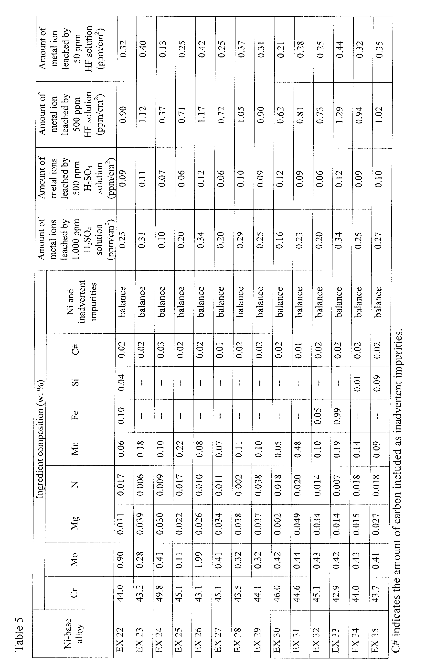
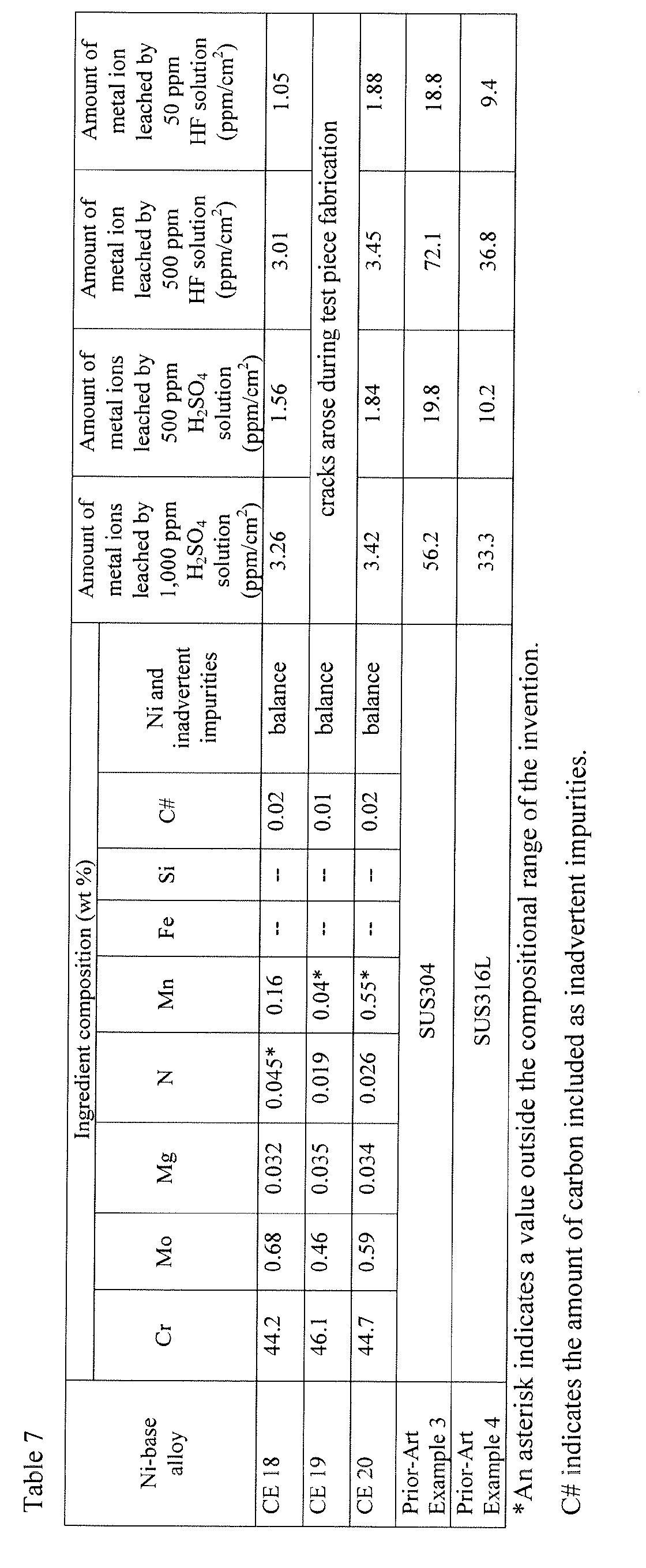
thereby producing 12 mm thick ingots of the ingredient compositions shown in Tables 5
to 7. These ingots were subjected to homogenizing heat treatment at 1230°C for 10
hours. Next, while maintaining the temperature within a range of 1000 to 1230°C, the
ingots were reduced to a final thickness of 5 mm by hot rolling at a thickness reduction
rate of 1 mm per pass. The resulting plates were then subjected to solution heat treatment
in which they were held at 1200°C for 30 minutes then water quenched. Next, the
surfaces were buffed, giving nickel-base alloy plates 22 to 41 according to the invention
(Examples) and comparative nickel-base alloy plates 11 to 20 (Comparative Examples)
having the ingredient compositions shown in Tables 5 to 7.
In a similar process, low carbon-content starting materials were melted and cast in
an ordinary high-frequency melting furnace, thereby producing 5 mm thick precision-cast
ingots of the ingredient compositions shown in Table 6. These ingots were subjected to
homogenizing heat treatment at 1230°C for 10 hours, then were water quenched. This
procedure yielded a nickel-base alloy plate 42 according to the invention (Example).
A prior-art alloy plate 3 (Prior-Art Example) made of SUS304 stainless steel and
having a thickness of 5 mm and a prior-art alloy plate 4 (Prior-Art Example) made of
SUS316L stainless steel and of the same thickness were also prepared.
These inventive nickel-base alloy plates 22 to 41 (Examples), comparative nickel-base
alloy plates 11-20 (Comparative Examples) and prior-art alloy plates 3 and 4 (Prior-Art
Examples) were each cut into test pieces having a length of 10 mm and a width of 50
mm. The test pieces were surface polished by finishing with waterproof emery paper
#400, following which they were ultrasonically degreased in acetone for five minutes.
A 1,000 ppm H2SO4 solution and a 500 ppm H2SO4 solution were prepared as test
solutions which simulate the sulfuric acid acidic water that forms in the environment for
forming a polymer electrolyte fuel cell. A 500 ppm HF solution and a 50 ppm HF
solution were also prepared as test solutions which simulate the hydrofluoric acid acidic
water that forms in the environment for forming a polymer electrolyte fuel cell. In
addition, polypropylene test containers were prepared for use.
The test pieces from inventive nickel-base alloy plates 22 to 41 (Examples),
comparative nickel-base alloy plates 1 1 to 20 (Comparative Examples) and prior-art alloy
plates 3 and 4 (Prior-Art Examples) were individually placed, together with 200 ml
portions of the test solutions prepared above, in the polypropylene test containers. These
were then vacuum degassed in a glove box, and sealed by closure with a lid within a
hydrogen atmosphere. These sealed polypropylene test containers were placed in a test
chamber set at 80°C and held therein for 500 hours.
The polypropylene test containers were subsequently removed and cooled,
following which the elements that leached out into the H
2SO
4 solutions and the HF
solutions were quantitatively determined by inductively coupled plasma emission
spectroscopy, and the total amount of metal ions that leached from each test piece was
measured. This total amount of leached metal ions was divided by the surface area of the
test piece to give the amount of leached metal ions per unit surface area. The results are
shown in Tables 5 to 7.
As is apparent from the results shown in Tables 5 to 7, the nickel-base alloy plates
in Examples 22 to 42 according to the fifth and sixth aspects of the invention have much
lower amounts of metal ion leached per unit surface area of the test pieces than the alloy
plates 3 and 4 in Prior-Art Examples 3 and 4. The test pieces from the nickel-base alloy
plates in Comparative Examples 11 to 20, which fall outside the scope of this invention,
either had somewhat high amounts of metal ions leached or gave rise in most cases to
cracks during machining of the test plates.
INDUSTRIAL APPLICABILITY
The nickel-base alloys of the invention undergo very little leaching of metal ions
in an environment for forming a polymer electrolyte fuel cell. Therefore, by assembling
polymer electrolyte fuel cells using components made of the nickel-base alloys of the
invention, deterioration of the solid electrolyte membrane can be suppressed, enabling
polymer electrolyte fuel cells with a longer lifetime to be achieved. This invention will
thus be of great industrial benefit.
As noted above, the nickel-base alloys of the invention are most effective when
used in an environment for forming a polymer electrolyte fuel cell containing sulfuric
acid or hydrofluoric acid. However, these nickel-base alloys are not limited only to use
under such circumstances, and also undergo very little leaching of metal ions in an
environment for forming a polymer electrolyte fuel cell containing formic acid.
Furthermore, in addition to use in polymer electrolyte fuel cells, the inventive metal-base
alloys can also be used to make components for drug manufacturing equipment from
which the leaching of metal ions cannot be tolerated.