EP1595941A2 - Microinjectiuon device and microinjection method - Google Patents
Microinjectiuon device and microinjection method Download PDFInfo
- Publication number
- EP1595941A2 EP1595941A2 EP05251126A EP05251126A EP1595941A2 EP 1595941 A2 EP1595941 A2 EP 1595941A2 EP 05251126 A EP05251126 A EP 05251126A EP 05251126 A EP05251126 A EP 05251126A EP 1595941 A2 EP1595941 A2 EP 1595941A2
- Authority
- EP
- European Patent Office
- Prior art keywords
- cell
- substrate
- needle
- image
- microinjection
- Prior art date
- Legal status (The legal status is an assumption and is not a legal conclusion. Google has not performed a legal analysis and makes no representation as to the accuracy of the status listed.)
- Withdrawn
Links
Images










Classifications
-
- C—CHEMISTRY; METALLURGY
- C12—BIOCHEMISTRY; BEER; SPIRITS; WINE; VINEGAR; MICROBIOLOGY; ENZYMOLOGY; MUTATION OR GENETIC ENGINEERING
- C12M—APPARATUS FOR ENZYMOLOGY OR MICROBIOLOGY; APPARATUS FOR CULTURING MICROORGANISMS FOR PRODUCING BIOMASS, FOR GROWING CELLS OR FOR OBTAINING FERMENTATION OR METABOLIC PRODUCTS, i.e. BIOREACTORS OR FERMENTERS
- C12M35/00—Means for application of stress for stimulating the growth of microorganisms or the generation of fermentation or metabolic products; Means for electroporation or cell fusion
Definitions
- the present invention relates to a technology for trapping a cell in a hole and injecting a substance into the cells with a needle.
- a gene can be injected into a cell with various methods that include an electrical method (electropolation), a chemical method (lipofection), a biological method (vector method), a mechanical method (microinjection), and an optical method (laser injection).
- an electrical method electropolation
- a chemical method lipofection
- a biological method vector method
- microinjection mechanical method
- laser injection laser injection
- the electrical method causes severe damage to the cells
- the chemical method has poor efficiency
- the biological method has a defect that not all the materials can be introduced in the cells.
- the mechanical method has received high attention as a method that is safest and exhibits high efficiency.
- Gazette of Japanese Patent No. 2,624,719 discloses a method that performs microinjection using a capillary (injection needle) as one example of a conventional mechanical method.
- Fig. 22 is a schematic for explaining this method.
- an Si chip also referred to as Si substrate
- a culture fluid also referred to as medium
- injections are performed in a state in which the holes fully filled with the culture fluid.
- the holes have a diameter of the order of few micrometers ( ⁇ m) and are smaller than the cells, which have a diameter of about 10 ⁇ m to 15 ⁇ m, so that the cell do not pass through the holes and remain on the Si chip 12.
- ⁇ m the order of few micrometers
- the culture fluid flows through the holes, however, the cells that flow along with the culture liquid can not pass through the holes and therefore get trapped in the holes due to the suction force. Then, a drug solution is injected into the trapped cells using an injection needle 11. A lot of cells can be processed if there are a lot of holes.
- the tip of the injection needle 11 must be projected toward the central the cell at a precision of ⁇ 2 ⁇ m to ⁇ 3 ⁇ m.
- the position of the needle cannot be controlled so accurately.
- Fig. 23 is a schematic for explaining these reasons in detail.
- Fluctuation of the position of the injection needle 11 is mainly due to thermal fluctuation of the shape of a needle holding mechanism (mainly in the y direction).
- a needle holding mechanism mainly in the y direction.
- an XYZ table that moves the Si chip 12 has position setting errors of several microns (in the x direction, y direction, and z direction).
- errors of the order of few ⁇ m
- there are errors (of the order of few ⁇ m) in manufacturing silicon substrates, errors in alignment between the Si chip 12 and a Petri dish, and so on.
- Fluctuation of the shape and position of cells include fluctuation of cell size, deviation in the centers of the holes and the cells, and so on. Since cells are living, individual cell is different in size, and generally the cells are not perfect spheres, which also make the control of the needle difficult.
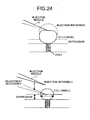
- Fig. 24 is a schematic for explaining influence of variations in the height direction (z direction) of the injection needle and variations in the size of the cell size on the injection process.
- the surface of the Si chip is depressed and the direction of the injection needle 11 is nearly parallel to the surface of the membrane of the cell, so that the tip of the injection needle 11 cannot break the cell membrane.
- the injection needle 11 does not reach the cell, so that injection can be performed.
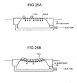
- the portion of the Si chip 12 where the holes are formed is 10 ⁇ m to 20 ⁇ m thick. Therefore, if a large number of holes are formed to perform injection to more cells at one time, the mechanical strength of this portion reduces, so that the height of this portion changes largely due to the suction from below. The amount of change in the height depends on the strength of the suction and the number of cells adsorbed.
- Fig. 25A is a schematic to explain the deformation of the substrate when only a few cells are trapped in the holes.
- the culture fluid flows through the unoccupied holes, so that the substrate deforms less.
- Fig. 25B when a large number of cells are adsorbed, the number of unoccupied holes s is small, so that when suction is continued at a constant rate, the pressure of suction portion decreases, resulting in a fluctuation of height of the substrate.
- the largest amount of the fluctuation is defined as a maximum deformation (see Fig. 26A).
- Fig. 26B is a graph of amount of suction against amount of deformation with adsorption ratio of cells as a parameter. When no cells are adsorbed, deformation occurs to some extent. However, the amount of deformation increases with the adsorption ratio. Therefore, a method that can control the amount of deformation to a constant value is necessary.
- a microinjection apparatus includes a substrate having a hole for trapping a cell using suction force and injecting a substance into the cell with a needle; an image acquiring unit that acquires an image of a region on the substrate, the image having characteristics that change based on a deformation of the substrate; a calculating unit that calculates an amount of deformation of the substrate based on the image acquired; and a controlling unit that controls a relative position of the needle and the substrate based on the amount of deformation.
- a microinjection apparatus includes a substrate having a hole for trapping a cell using suction force and injecting a substance into the cell with a needle; a searching unit that searches a cell-free region that is a region where no cells exist on the substrate; a calculating unit that calculates a center of the cell-free region; a needle controlling unit that controls the needle so that a tip of the needle approaches the center of the cell-free region; a measuring unit that measures a position of the tip using an image of the tip while the needle is being controlled by the controlling unit; and a controlling unit that controls a relative position of the needle and the substrate based on the position of the needle measured.
- a microinjection apparatus includes a substrate having a hole for trapping a cell using suction force and injecting a substance into the cell with a needle; a measuring unit that measures a size of a cell that is trapped in the hole; and a controlling unit that controls a relative position of the needle and the substrate based on the size of the cell measured.
- a microinjection method includes trapping a cell in a hole provided in a substrate with suction force and injecting a substance into the cell with a needle; acquiring an image of a region on the substrate, the image having characteristics that change based on a deformation of the substrate; calculating an amount of deformation of the substrate based on the image acquired; and controlling a relative position of the needle and the substrate based on the amount of deformation.
- a microinjection method includes trapping a cell in a hole provided in a substrate with suction force and injecting a substance into the cell with a needle; searching a cell-free region that is a region where no cells exist on the substrate; calculating a center of the cell-free region; controlling the needle so that a tip of the needle approaches the center of the cell-free region; measuring a position of the tip using an image of the tip while the needle is being controlled; and controlling a relative position of the needle and the substrate based on the position of the needle measured.
- a microinjection method includes trapping a cell in a hole provided in a substrate with suction force and injecting a substance into the cell with a needle; measuring a size of a cell that is trapped in a hole; and controlling a relative position of the needle and the substrate based on the size of the cell.
- a microinjection apparatus includes a substrate having a hole for trapping a cell using suction force and injecting a substance into the cell with a needle; a recess around each of the holes.
- Fig. 1 is a perspective of a Si chip (Si substrate) used in a microinjection apparatus according to a first embodiment.
- An Si chip (Si substrate) 12 is provided with a plurality of height detection marks 13 and these height detection marks 13 are used for adjusting the needle position with respect to the fluctuation of the height of the substrate.
- each height detection mark 13 includes a pattern made of a plurality of fine lines. These lines are parallel to the surface of the Si chip.
- the height detection marks 13 are formed at various positions. For example, the height detection marks 13 are formed in the center and the periphery of the region where holes are formed, and even in regions where no holes are formed.
- the microinjection apparatus can measure the posture of the Si chip and flexure of hole forming region by measuring height of each of the patterns.
- Fig. 2 is a perspective of a substrate height measuring optical system of the microinjection apparatus according to the first embodiment.
- the substrate height measuring optical system includes a water-immersed objective lens that enlarges each of the patterns on the surface of the Si chip and a CCD camera that observes each of the patterns.
- the Si chip 12 is adhered to a Petri dish provided with a perforated portion.
- a suction hole for sucking air through the perforated portion of the Petri dish, is formed in a board that holds the Petri dish.
- the suction hole is connected to a suction pump (not shown) through a tube and the suction pump sucks a culture solution (fluid).
- the suction rate of the suction pump can be set as desired.
- the board that holds the Petri dish is placed on an XYZ table 14.
- Fig. 3A is a schematic of an image obtained by the CCD camera.
- the CCD camera is adjusted in such a manner that the center of the pattern is in the center of the view of the CCD camera. (The observation line is directed so as to align the direction of scanning pixels of the CCD camera. In this direction, measurement with less measurement errors is possible.)
- Fig. 3B is an example of a height measuring signal output by the CCD camera.
- a signal having a large amplitude and high visibility is output.
- the visibility decreases when the focus is offset. Accordingly, by calculating the visibility, the relationship between the height of the substrate and the objective lens can be measured and an amount of depression of the substrate can be calculated.
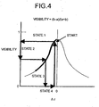
- Fig. 4 is a schematic for explaining how the height of the substrate can be adjusted using the visibility.
- the horizontal axis indicates the height of surface of the Si chip 12 and focused focal point height is taken 0.
- the vertical axis indicates visibility.
- the substrate is in only slightly depressed state (state 1) because very few cells fit in the holes, and therefore, the visibility if high. As more and more cells fit in the holes, the visibility decreases (state 2), because, the amount of deformation increase (state 3).
- the XYZ table 14 is moved (or the objective lens is moved) in the Z direction to obtain higher visibility.
- the amount of depression can be maintained at a constant value. By removing extra cells after adsorption of the cells, this state is stabilized.
- the relationship between the visibility and the amount of depression is acquired beforehand and the relationship between pressure and flexure is measured beforehand.
- the visibility is calculated by using the height detection mark 13 provided on the surface of the Si chip 12 and observing an image of the height detection mark 13, an amount of depression of the Si chip 12 is calculated using the relationship between the calculated visibility and the height of the Si chip 12, and the XYZ table 14 is moved based on the amount of depression. Accordingly, the depression of the Si chip 12 can be compensated for with good precision. Outer peripheries of the hole in the Si chip 12 for trapping the cells can also be used as height detection marks instead of the above-mentioned patterns.
- a microinjection apparatus is configured so as to adjust the height of the injection needle 11 along with the movement in the horizontal direction of the XYZ table 14. First, the necessity of adjusting the height of the injection needle 11 is explained.
- Fig. 5 is a schematic for explaining the necessity of adjustment of the height of the injection needle 11.
- the XYZ table 14 is generally not perfectly horizontal. Since the injection needle 11 projects toward the center of the cell, the distance between the tip of the injection needle 11 and the surface of the Si chip is only about 5 ⁇ m. Therefore, when the XYZ table 14 moves in the horizontal direction, injection to the cell that is trapped on the Si chip 12 becomes impossible. Further, in some cases the injection needle 11 may collide with the Si chip 12 thereby causing damage.
- the holes When there are a large number of holes in the Si chip, the holes occupy a wider area on the Si chip, resulting in an increase in fluctuation of the height of the chip and an increase in the amount of flexure. As a result, the movement of the XYZ table 14 may bring about a situation where the injection needle 11 collides with the Si chip 12 thereby causing damage.
- the microinjection apparatus measures a distance (height) between the needle tip and the surface of the Si chip and provides a control so as to maintain a predetermined constant distance between them.
- This arrangement makes it possible to project the injection needle 11 toward the center of the cell and also prevent damage due to collision of the injection needle 11 with the Si chip 12.
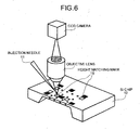
- Fig. 6 is a perspective for explaining the method of measuring the distance between the Si chip surface and the needle tip.
- a plurality of height matching marks 15 are provided on the surface of the Si chip 12.
- the height matching marks 15 are flat, have a predetermined area (10 ⁇ m 2 to 20 ⁇ m 2 ), and reflect light.
- Well-polished silicon surfaces can be used as the height matching marks 15.
- metal surfaces can be used as the height matching marks 15. However, if the metal surfaces used, it is preferable that the metal surfaces be provided with a protective coating of SiO 2 so that the metal does not directly come in contact with the culture solution.
- the microinjection apparatus is configured such that the tip of the injection needle 11 is positioned near the center of the height matching mark 15 and a real image of the real tip and a mirror image of the tip seen in the height matching mark 15 are observed.
- An objective lens and a CCD camera are used for the observation.
- Fig. 7A is a schematic for explaining the formation of the real image and Fig. 7-2 is a cross-sectional view for explaining the formation of the mirror image.
- the microinjection apparatus according to the second embodiment determines shifts in position ⁇ z in the height direction of the real image and mirror image and make the values 1/2 to measure the height of the needle.
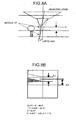
- Fig. 8A is an explanatory diagram for explaining another method for measuring the height of the injection needle. In this method, the injection needle is slightly moved away horizontally from the optic axis of the objective lens.
- Fig. 8B is a schematic of an image obtained in the situation shown in Fig. 8A.
- the objective lens of a microscope forms an image such that when an angle ( ⁇ ) from the center of the lens is different, an image is formed at a different position, so that the mirror image and the real image are formed slightly different positions in the same plane.
- the real image and the mirror image of the injection needle are measured using the height matching marks 15 provided on the surface of the Si chip 12, and the height from the injection needle 11 is measured based on the shifts of position of the real image and the mirror image in the direction of height, so that the distance between the injection needle 11 and the Si chip 12 can be maintained at a predetermined value by moving the XYZ table 14 up and down based on the measured height.
- the up and down movement of the XYZ table 14 is calculated using the direction of movement, distance of movement and inclination of the XYZ table 14, and the height of the XYZ table 14 is controlled so as to correct the calculated up and down movement of the XYZ table, resulting in that the injection needle 11 and the surface of the Si chip can be always maintained at a constant distance.
- a microinjection apparatus if configured so as to adjust the position of the needle based on the fluctuation in position of the injection needle tip.
- the fluctuation in position of the injection needle tip is explained.
- Fig. 9 is a perspective for explaining the fluctuation in the position of the tip of the injection needle.
- the injection needle 11 may fluctuate in a horizontal plane in the x- and y-directions and make the injection impossible.
- the injection needle 11 can fluctuate due to deformation of a needle holding mechanism or deformation of the needle itself due to a change in surrounding temperature. Due to structural peculiarities of the needle, it fluctuates more in the y-direction than in the x-direction.
- Fig. 10 is a schematic for explaining the problems caused due to the fluctuation of the injection needle 11. Not all the cells are absorbed in the hole, i.e., some cells may exist in a portion other than the holes. If a cell exists below the injection needle 11 while the injection needle 11 fluctuates, an image having a poor contrast is obtained, so that the position of the tip cannot be determined accurately.
- the microinjection apparatus searches a cell-free region out of the image including cells in order to accurately measure the position of the needle tip.
- Fig. 11A is a schematic for explaining a method of searching a cell-free region according to the third embodiment of the present invention.
- the image is scanned using a region slightly larger than a cell (about 20 ⁇ m in diameter) as a template to search a cell-free region.
- the searched cell-free region is shown as hatched.
- the cell-free region is defined by the trajectory of the center of the search template.
- the center position of the largest region among the cell-free regions thus searched is obtained.
- the point shown with a cross is the center position of the largest cell-free region.
- the y-coordinate of the needle center is obtained and the XYZ table 14 is moved so that the y-coordinate of the center position shown with the cross coincide with the y-coordinate of the needle center (see Fig. 11 B).
- the y-coordinate is considered here, because, the needle fluctuates greater in the y direction than the x-direction.
- Fig. 11 B an image in which no cell exists under the needle can be obtained.
- the tip position of the needle is measured form this image.
- the tip position is obtained by detecting a confocal state of the image and measuring from the tip position.
- a cell-free region is searched and the XYZ table 14 is moved so that the tip position of the injection needle 11 comes to a region where no cells exist, so that the tip position of the injection needle 11 can be determined accurately.
- a microinjection apparatus is configured so as to adjust the needle position with respect to the fluctuation of attachment position of cells.
- Fig. 12A is a schematic for explaining migration of a cell.
- the microinjection apparatus adjusts the direction of movement of the injection needle and the position of the cell by moving the XYZ table 14.
- the microinjection apparatus performs injection in a middle point between the center of the cell and the center of the hole (position shifted by ⁇ in Fig. 12B) taking into consideration adsorption force and resistance in the fluid within the cell ( ⁇ is shown in Fig. 12B).
- the positions of the holes are known in advance, so that the displacement of the cell from the center of the hole can be calculated by determining the center of the cell. If the calculated center of the cell is not in a predetermined range of the center of the hole, no injection is performed.
- Fig. 13 is a schematic for explaining an example of a method for determining the center of the cell. Based on the fact that cells are substantially spherical, circles that resemble the contour of the cell are obtained. Then, an approximation circle that shows the smallest difference in area between the contour of the cell and the approximate circle is selected and the size and center position of this circle is defined as the position of the cell.
- a shift in the center of the cell is obtained by measuring the center position of the cell and obtaining a difference from the position of the hole, so that the position of the XYZ table 14 can be adjusted based on the obtained shift and injection into the cell can be performed accurately.
- a microinjection apparatus is configured so as to adjust the position of needle with respect to the fluctuation of the cell size. First, correction of position of injection with respect to the fluctuation of the cell size is explained.
- Fig. 14 is a schematic for explaining the effect of the size of the cell on the injection position. Since there are cells of various sizes, it is necessary to change the position of injection for each cell.
- Fig. 14 shows a plan view (above) and a cross-sectional view (below) for cases where injection is performed into a large cell A (solid line) and a small cell B (broken line), respectively.
- the microinjection apparatus measures the size of the cell and adjusts the position of the XYZ table 14 based on the size of the cell.
- the size of the cell is measured and the position of the XYZ table is adjusted based on the size of the cell, so that injection can be performed accurately even when the size of the cell fluctuates.
- a microinjection apparatus is configured so as to prevent migration of cells when injection is performed.
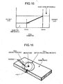
- Fig. 16 is a schematic for explaining the migration of a cell while the injection is performed.
- the microinjection apparatus traps cells by suction of a culture broth from below through holes formed in the Si substrate. If the holes are 1/3 times the size of the cells, the cells pass through the hole. On the other hand, if the holes are small, problems occur that the cells do not get trapped easily, the cells do not firmly fix in the holes, and the cells move, so that the needle cannot penetrate the cell membrane, as shown in Fig. 16.
- the diameters of the holes are made smaller (about 1/10 times the cell diameter) so that the cell does not pass through the holes, and a recess having a diameter of about 80% of the cell diameter is formed around each of the holes. Because the cells fit in these recesses, migration of the cell can be prevented.
- Fig. 17B is a perspective of a cell trapped in the recess shown in Fig. 17A.
- the cell deforms more or less when the injection needle cell is injected in the cell, however, the cell does not migrate because it is fit in the recess, so that injection can be performed easily.
- Fig. 18 is a cross-sectional view of the substrate in a situation where a cell is trapped in the recess. When the cell touches the bottom of the recess, the cell can be trapped stably.
- Fig. 19 is a plan view of the situation shown in Fig. 18.
- the diameters of the holes are made about 1/10 time the cell diameter and a recess having a diameter of about 80% of the cell diameter is formed around each of the holes, so that the cells fit in these recesses and do not move when injection is performed.
- Fig. 20 is a plan view of a substrate according to a seventh embodiment of the present invention.
- This substrate according to the seventh embodiment is provided with both the height detection marks 13 as in the first embodiment and the height matching marks 15,as in the second embodiment.
- the Si chip 12 has chevron marks that indicate main directions and cross marks as alignment marks in the periphery and the height detection mark 13 and the height matching mark 13 as adjustment marks in the region where the holes are present.
- the center portion of the region where the holes are present deforms the most so that the height detection mark 13 and the height matching mark 15 are provided in and around this region.
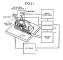
- Fig. 21 is a schematic of an injection position adjustment system according to an eighth embodiment of the present invention.
- This injection position adjustment system can be used in any of the first to the seventh embodiments.
- the injection position adjustment system acquires an image using a CCD camera and measures the positions of the cell, the injection needle 11, and so on.
- control of the suction amount of a suction pump 17, up and down of the XYZ table 14 and detection optical system, adjustment of the position of an injector and so on is performed. Then, after the detection position is adjusted, operations such as projection of the injection needle 11 and ejection the drug solution are performed. These operations are controlled by a controller 16.
- the present invention since the injection position is controlled with high precision, the present invention has an effect that the substance can be injected into the cell reliably.
Landscapes
- Life Sciences & Earth Sciences (AREA)
- Engineering & Computer Science (AREA)
- Health & Medical Sciences (AREA)
- Wood Science & Technology (AREA)
- Biotechnology (AREA)
- Genetics & Genomics (AREA)
- Bioinformatics & Cheminformatics (AREA)
- Organic Chemistry (AREA)
- Chemical & Material Sciences (AREA)
- Zoology (AREA)
- Cell Biology (AREA)
- Sustainable Development (AREA)
- Microbiology (AREA)
- Biochemistry (AREA)
- General Engineering & Computer Science (AREA)
- General Health & Medical Sciences (AREA)
- Biomedical Technology (AREA)
- Apparatus Associated With Microorganisms And Enzymes (AREA)
- Micro-Organisms Or Cultivation Processes Thereof (AREA)
Abstract
Description
Claims (19)
- A microinjection apparatus comprising:a substrate having a hole for trapping a cell using suction force and injecting a substance into the cell with a needle;an image acquiring unit that acquires an image of a region on the substrate, the image having characteristics that change based on a deformation of the substrate;a calculating unit that calculates an amount of deformation of the substrate based on the image acquired; anda controlling unit that controls a relative position of the needle and the substrate based on the amount of deformation.
- The microinjection apparatus according to claim 1, wherein a pattern of fine, parallel lines is provided in the region on the substrate,
the image acquiring unit acquires an image of the pattern,
the calculating unit calculates the amount of deformation using a change in signal intensities of the pattern in the image acquired, and calculates an amount of correction based on the amount of deformation, and
the controlling unit controls the relative position of the needle and the substrate based the amount of correction. - The microinjection apparatus according to claim 1, wherein a reflecting member that reflects light is provided in the region,
the image acquiring unit acquires a real image and a mirror image, which is a projection of a tip of the needle in the reflecting member,
the calculating unit that calculates a distance between the tip and the substrate using the real image and the mirror image, and
the controlling unit controls the relative position of the needle and the substrate so that the distance between the tip and the substrate is maintained at a predetermined value when the substrate and the needle move relatively in a horizontal direction. - The microinjection apparatus according to claim 3, the image acquiring unit includes an optical system, wherein the image acquiring unit acquires the real image and the mirror image simultaneously by shifting the optical system in a horizontal direction.
- The microinjection apparatus according to claim 1, wherein the image acquiring unit is a charged coupled device camera.
- The microinjection apparatus according to claim 1, wherein the substrate is made of silica.
- A microinjection apparatus comprising:a substrate having a hole for trapping a cell using suction force and injecting a substance into the cell with a needle;a searching unit that searches a cell-free region that is a region where no cells exist on the substrate;a calculating unit that calculates a center of the cell-free region;a needle controlling unit that controls the needle so that a tip of the needle approaches the center of the cell-free region;a measuring unit that measures a position of the tip using an image of the tip while the needle is being controlled by the controlling unit; anda controlling unit that controls a relative position of the needle and the substrate based on the position of the needle measured.
- The microinjection apparatus according to claim 7, wherein the substrate is made of silica.
- A microinjection apparatus comprising:a substrate having a hole for trapping a cell using suction force and injecting a substance into the cell with a needle;a measuring unit that measures a size of a cell that is trapped in the hole; anda controlling unit that controls a relative position of the needle and the substrate based on the size of the cell measured.
- The microinjection apparatus according to claim 9, wherein the substrate is made of silica.
- A microinjection method including trapping a cell in a hole provided in a substrate with suction force and injecting a substance into the cell with a needle, comprising:acquiring an image of a region on the substrate, the image having characteristics that change based on a deformation of the substrate;calculating an amount of deformation of the substrate based on the image acquired; andcontrolling a relative position of the needle and the substrate based on the amount of deformation.
- The microinjection method according to claim 11, wherein the substrate is made of silica.
- A microinjection method including trapping a cell in a hole provided in a substrate with suction force and injecting a substance into the cell with a needle, comprising:searching a cell-free region that is a region where no cells exist on the substrate;calculating a center of the cell-free region;controlling the needle so that a tip of the needle approaches the center of the cell-free region;measuring a position of the tip using an image of the tip while the needle is being controlled; andcontrolling a relative position of the needle and the substrate based on the position of the needle measured.
- The microinjection method according to claim 13, wherein the substrate is made of silica.
- A microinjection method including trapping a cell in a hole provided in a substrate with suction force and injecting a substance into the cell with a needle, comprising:measuring a size of a cell that is trapped in a hole; andcontrolling a relative position of the needle and the substrate based on the size of the cell.
- The microinjection method according to claim 15, wherein the substrate is made of silica.
- A microinjection apparatus comprising:a substrate having a hole for trapping a cell using suction force and injecting a substance into the cell with a needle;a recess around each of the holes.
- The microinjection apparatus according to claim 17, wherein the substrate is made of silica.
- The microinjection apparatus according to claim 17, wherein a diameter of the recess is about 80% of a diameter of the cell.
Applications Claiming Priority (2)
| Application Number | Priority Date | Filing Date | Title |
|---|---|---|---|
| JP2004140289 | 2004-05-10 | ||
| JP2004140289A JP4504089B2 (en) | 2004-05-10 | 2004-05-10 | Microinjection apparatus and microinjection method |
Publications (2)
| Publication Number | Publication Date |
|---|---|
| EP1595941A2 true EP1595941A2 (en) | 2005-11-16 |
| EP1595941A3 EP1595941A3 (en) | 2007-02-14 |
Family
ID=34940515
Family Applications (1)
| Application Number | Title | Priority Date | Filing Date |
|---|---|---|---|
| EP05251126A Withdrawn EP1595941A3 (en) | 2004-05-10 | 2005-02-25 | Microinjectiuon device and microinjection method |
Country Status (3)
| Country | Link |
|---|---|
| US (1) | US20050250197A1 (en) |
| EP (1) | EP1595941A3 (en) |
| JP (1) | JP4504089B2 (en) |
Cited By (10)
| Publication number | Priority date | Publication date | Assignee | Title |
|---|---|---|---|---|
| EP1873232A1 (en) * | 2006-06-29 | 2008-01-02 | Fujitsu Limited | Microinjection apparatus and automatic focal point adjustment method |
| WO2008034249A1 (en) * | 2006-09-21 | 2008-03-27 | Yu Sun | High-throughput automated cellular injection system and method |
| EP1997878A1 (en) | 2007-05-31 | 2008-12-03 | Fujitsu Limited | Cell capturing plate, microinjection apparatus, and method of producing cell capturing plate |
| WO2009003487A3 (en) * | 2007-06-29 | 2009-05-07 | Unisense Fertilitech As | A device, a system and a method for monitoring and/or culturing of microscopic objects |
| US7897395B2 (en) | 2007-04-27 | 2011-03-01 | Fujitsu Limited | Microinjection apparatus, trap plate and microinjection method |
| WO2012037642A1 (en) * | 2010-08-20 | 2012-03-29 | Marksmen Cellject Inc. | System and method for automated sperm manipulation |
| US8265357B2 (en) | 2005-10-14 | 2012-09-11 | Unisense Fertilitech A/S | Determination of a change in a cell population |
| EP1884780A3 (en) * | 2006-07-28 | 2014-03-05 | Fujitsu Ltd. | Microinjection apparatus and microinjection method |
| GB2508906A (en) * | 2012-12-14 | 2014-06-18 | Life Science Methods Bv | Frame element for sample injection with optical control means |
| CN106730106A (en) * | 2016-11-25 | 2017-05-31 | 哈尔滨工业大学 | The coordinate scaling method of the micro-injection system of robot assisted |
Families Citing this family (11)
| Publication number | Priority date | Publication date | Assignee | Title |
|---|---|---|---|---|
| JP4791164B2 (en) * | 2005-12-07 | 2011-10-12 | 富士通株式会社 | Microinjection apparatus and contact detection method |
| JP4828933B2 (en) * | 2005-12-22 | 2011-11-30 | 中央精機株式会社 | Minute substance transfer method |
| DE602007005340D1 (en) | 2007-01-19 | 2010-04-29 | Fujitsu Ltd | Capillary and method and apparatus for polishing capillaries |
| JP5103989B2 (en) * | 2007-03-30 | 2012-12-19 | 富士通株式会社 | Microinjection needle manufacturing apparatus and manufacturing method |
| US8247215B2 (en) * | 2007-01-26 | 2012-08-21 | Canon Kabushiki Kaisha | Apparatus for introducing substance into cells |
| CA2685615C (en) * | 2008-10-10 | 2018-01-16 | Mcmaster University | Single cell microinjection using flexible and compliant fluidic channels and electroosomotic dosage control |
| US9091725B2 (en) | 2009-07-03 | 2015-07-28 | Koh Young Technology Inc. | Board inspection apparatus and method |
| US8124437B2 (en) * | 2009-12-21 | 2012-02-28 | Du Pont Apollo Limited | Forming protrusions in solar cells |
| CN104140927A (en) * | 2014-07-31 | 2014-11-12 | 苏州大学 | Cell position and attitude adjusting chip, device and method |
| US12233406B2 (en) | 2021-08-04 | 2025-02-25 | City University Of Hong Kong | Automated system for high-throughput microinjection of adherent cells |
| CN114034225B (en) * | 2021-11-25 | 2024-08-20 | 广州市华粤行医疗科技有限公司 | Method for testing movement precision of injection needle under microscope |
Family Cites Families (10)
| Publication number | Priority date | Publication date | Assignee | Title |
|---|---|---|---|---|
| DE3718066A1 (en) * | 1987-05-29 | 1988-12-08 | Zeiss Carl Fa | METHOD FOR MICROINJECTION IN CELLS OR. FOR SUCTION FROM SINGLE CELLS OR WHOLE CELLS FROM CELL CULTURES |
| JP2624719B2 (en) * | 1987-10-28 | 1997-06-25 | 株式会社日立製作所 | Micro injection device |
| US5262128A (en) * | 1989-10-23 | 1993-11-16 | The United States Of America As Represented By The Department Of Health And Human Services | Array-type multiple cell injector |
| JPH05192171A (en) * | 1991-08-08 | 1993-08-03 | Hitachi Ltd | Microinjection method and its apparatus |
| JP3035608B2 (en) * | 1998-07-09 | 2000-04-24 | 農林水産省食品総合研究所長 | Microcapillary array, method for manufacturing the same, and substance injection device |
| FR2784189B3 (en) * | 1998-10-05 | 2000-11-03 | Commissariat Energie Atomique | BIOCHIP AND DEVICE FOR READING A BIOCHIP COMPRISING A PLURALITY OF MOLECULAR RECOGNITION AREAS |
| JP3442357B2 (en) * | 2000-08-25 | 2003-09-02 | 株式会社日立製作所 | Amphibian oocyte sample introduction device, amphibian oocyte sample introduction system, amphibian oocyte sample introduction method, amphibian oocyte production method, amphibian oocyte and method of selling or transferring it, as sensor for screening Method used, container, and analysis method |
| US20030152255A1 (en) * | 2002-02-14 | 2003-08-14 | Ngk Insulators, Ltd. | Probe reactive chip, apparatus for analyzing sample and method thereof |
| JP5010793B2 (en) * | 2002-07-09 | 2012-08-29 | 独立行政法人科学技術振興機構 | Method and apparatus for introducing intracellularly introduced substance into animal cells using electroinjection method |
| JP2005278480A (en) * | 2004-03-29 | 2005-10-13 | Fujitsu Ltd | Substance introduction device and substance introduction chip |
-
2004
- 2004-05-10 JP JP2004140289A patent/JP4504089B2/en not_active Expired - Fee Related
-
2005
- 2005-02-25 EP EP05251126A patent/EP1595941A3/en not_active Withdrawn
- 2005-02-28 US US11/066,296 patent/US20050250197A1/en not_active Abandoned
Cited By (19)
| Publication number | Priority date | Publication date | Assignee | Title |
|---|---|---|---|---|
| US8265357B2 (en) | 2005-10-14 | 2012-09-11 | Unisense Fertilitech A/S | Determination of a change in a cell population |
| EP1873232A1 (en) * | 2006-06-29 | 2008-01-02 | Fujitsu Limited | Microinjection apparatus and automatic focal point adjustment method |
| US7936939B2 (en) | 2006-06-29 | 2011-05-03 | Fujitsu Limited | Microinjection apparatus and automatic focal point adjustment method |
| EP1884780A3 (en) * | 2006-07-28 | 2014-03-05 | Fujitsu Ltd. | Microinjection apparatus and microinjection method |
| WO2008034249A1 (en) * | 2006-09-21 | 2008-03-27 | Yu Sun | High-throughput automated cellular injection system and method |
| EP2064311A4 (en) * | 2006-09-21 | 2014-09-24 | Yu Sun | High-throughput automated cellular injection system and method |
| US7897395B2 (en) | 2007-04-27 | 2011-03-01 | Fujitsu Limited | Microinjection apparatus, trap plate and microinjection method |
| EP1997878A1 (en) | 2007-05-31 | 2008-12-03 | Fujitsu Limited | Cell capturing plate, microinjection apparatus, and method of producing cell capturing plate |
| CN103642688B (en) * | 2007-06-29 | 2018-05-01 | 尤尼森斯繁殖技术公司 | For monitoring and/or cultivating the equipment, system and method for microscopic objects |
| CN101802166B (en) * | 2007-06-29 | 2013-12-11 | 尤尼森斯繁殖技术公司 | Devices, systems and methods for monitoring and/or culturing microscopic objects |
| WO2009003487A3 (en) * | 2007-06-29 | 2009-05-07 | Unisense Fertilitech As | A device, a system and a method for monitoring and/or culturing of microscopic objects |
| US20140141463A1 (en) * | 2007-06-29 | 2014-05-22 | Unisense Fertilitech A/S | Device, a system and a method for monitoring and/or culturing of microscopic objects |
| US9588104B2 (en) * | 2007-06-29 | 2017-03-07 | Unisense Fertilitech A/S | Device, a system and a method for monitoring and/or culturing of microscopic objects |
| CN103249829A (en) * | 2010-08-20 | 2013-08-14 | 孙钰 | System and method for automated sperm manipulation |
| US9340762B2 (en) | 2010-08-20 | 2016-05-17 | Yu Sun | Method for automated sperm manipulation and device for holding sperm and oocytes |
| WO2012037642A1 (en) * | 2010-08-20 | 2012-03-29 | Marksmen Cellject Inc. | System and method for automated sperm manipulation |
| GB2508906A (en) * | 2012-12-14 | 2014-06-18 | Life Science Methods Bv | Frame element for sample injection with optical control means |
| CN106730106A (en) * | 2016-11-25 | 2017-05-31 | 哈尔滨工业大学 | The coordinate scaling method of the micro-injection system of robot assisted |
| CN106730106B (en) * | 2016-11-25 | 2019-10-08 | 哈尔滨工业大学 | The coordinate scaling method of the micro-injection system of robot assisted |
Also Published As
| Publication number | Publication date |
|---|---|
| JP2005318851A (en) | 2005-11-17 |
| EP1595941A3 (en) | 2007-02-14 |
| JP4504089B2 (en) | 2010-07-14 |
| US20050250197A1 (en) | 2005-11-10 |
Similar Documents
| Publication | Publication Date | Title |
|---|---|---|
| EP1595941A2 (en) | Microinjectiuon device and microinjection method | |
| US6701633B2 (en) | Apparatus and method for measuring a shape using multiple probes | |
| KR100787401B1 (en) | Probe device with optical length-measuring device and method of inspecting probe | |
| JP6830406B2 (en) | Dispenser | |
| US20230228984A1 (en) | Dynamic detilt focus tracking | |
| TWI438395B (en) | Shape measurement device probe and shape measurement device | |
| US11525995B2 (en) | Imaging system | |
| US12556815B2 (en) | Spot error handling for focus tracking | |
| JP4831972B2 (en) | Micro manipulation system | |
| JP4033468B2 (en) | Nozzle tip position measuring device and spotting device using the same | |
| CN116125102A (en) | Atomic Force Microscope and Its Probe Calibration Method | |
| US20090291502A1 (en) | Gene injection apparatus and gene injection method | |
| US20100031402A1 (en) | Probe aligning method for probe microscope and probe microscope operated by the same | |
| CN113237425B (en) | Automatic guidance method for measuring tiny workpieces with single-camera-assisted coordinate measuring machine | |
| EP1801198A1 (en) | Injection apparatus and method | |
| CN114054938B (en) | Laser processing equipment and laser processing methods | |
| JP2024516240A (en) | Scanning probe microscope system, optical microscope, calibration structure, and method for calibration in a scanning probe microscope device - Patents.com | |
| US20100017920A1 (en) | Scanning probe microscope with tilted sample stage | |
| US20060240566A1 (en) | Delivery of metered amounts of liquid materials | |
| JP4652795B2 (en) | Ranging method, tilt detection method, and flip chip mounting method | |
| US7361921B2 (en) | Device and method for plane-parallel orientation of a the surface of an object to be examined in relation to a focus plane of a lens | |
| CN110436406B (en) | A system and method for automatic and precise positioning and preparation of solid-state nanopore arrays | |
| JPH0536768A (en) | Probe apparatus | |
| KR20030076285A (en) | Method and device for determining the vectorial distance between the capillary and the image recognition system of a wire bonder | |
| NO316948B1 (en) | Method and device for manufacturing an accurate positioning of optical microcomponents on an optical device |
Legal Events
| Date | Code | Title | Description |
|---|---|---|---|
| PUAI | Public reference made under article 153(3) epc to a published international application that has entered the european phase |
Free format text: ORIGINAL CODE: 0009012 |
|
| AK | Designated contracting states |
Kind code of ref document: A2 Designated state(s): AT BE BG CH CY CZ DE DK EE ES FI FR GB GR HU IE IS IT LI LT LU MC NL PL PT RO SE SI SK TR |
|
| AX | Request for extension of the european patent |
Extension state: AL BA HR LV MK YU |
|
| PUAL | Search report despatched |
Free format text: ORIGINAL CODE: 0009013 |
|
| AK | Designated contracting states |
Kind code of ref document: A3 Designated state(s): AT BE BG CH CY CZ DE DK EE ES FI FR GB GR HU IE IS IT LI LT LU MC NL PL PT RO SE SI SK TR |
|
| AX | Request for extension of the european patent |
Extension state: AL BA HR LV MK YU |
|
| 17P | Request for examination filed |
Effective date: 20070416 |
|
| AKX | Designation fees paid |
Designated state(s): DE FR GB |
|
| 17Q | First examination report despatched |
Effective date: 20130612 |
|
| STAA | Information on the status of an ep patent application or granted ep patent |
Free format text: STATUS: THE APPLICATION IS DEEMED TO BE WITHDRAWN |
|
| 18D | Application deemed to be withdrawn |
Effective date: 20140103 |