EP1595758A1 - Seat-belt retractor - Google Patents
Seat-belt retractor Download PDFInfo
- Publication number
- EP1595758A1 EP1595758A1 EP04706287A EP04706287A EP1595758A1 EP 1595758 A1 EP1595758 A1 EP 1595758A1 EP 04706287 A EP04706287 A EP 04706287A EP 04706287 A EP04706287 A EP 04706287A EP 1595758 A1 EP1595758 A1 EP 1595758A1
- Authority
- EP
- European Patent Office
- Prior art keywords
- take
- drum
- plate body
- wire
- energy
- Prior art date
- Legal status (The legal status is an assumption and is not a legal conclusion. Google has not performed a legal analysis and makes no representation as to the accuracy of the status listed.)
- Granted
Links
- 230000007246 mechanism Effects 0.000 claims description 48
- 238000010521 absorption reaction Methods 0.000 abstract description 18
- 230000004048 modification Effects 0.000 description 6
- 238000012986 modification Methods 0.000 description 6
- 239000000463 material Substances 0.000 description 4
- 239000011347 resin Substances 0.000 description 3
- 229920005989 resin Polymers 0.000 description 3
- 238000005452 bending Methods 0.000 description 2
- 238000010276 construction Methods 0.000 description 2
- 238000010586 diagram Methods 0.000 description 2
- 230000001133 acceleration Effects 0.000 description 1
- 238000005516 engineering process Methods 0.000 description 1
- 230000002452 interceptive effect Effects 0.000 description 1
- 238000003475 lamination Methods 0.000 description 1
- 238000004519 manufacturing process Methods 0.000 description 1
- 239000002184 metal Substances 0.000 description 1
- 238000000465 moulding Methods 0.000 description 1
- 230000004044 response Effects 0.000 description 1
- 230000000717 retained effect Effects 0.000 description 1
- 238000004804 winding Methods 0.000 description 1
Images


Classifications
-
- B—PERFORMING OPERATIONS; TRANSPORTING
- B60—VEHICLES IN GENERAL
- B60R—VEHICLES, VEHICLE FITTINGS, OR VEHICLE PARTS, NOT OTHERWISE PROVIDED FOR
- B60R22/00—Safety belts or body harnesses in vehicles
- B60R22/34—Belt retractors, e.g. reels
- B60R22/341—Belt retractors, e.g. reels comprising energy-absorbing means
- B60R22/3413—Belt retractors, e.g. reels comprising energy-absorbing means operating between belt reel and retractor frame
-
- B—PERFORMING OPERATIONS; TRANSPORTING
- B60—VEHICLES IN GENERAL
- B60R—VEHICLES, VEHICLE FITTINGS, OR VEHICLE PARTS, NOT OTHERWISE PROVIDED FOR
- B60R22/00—Safety belts or body harnesses in vehicles
- B60R22/28—Safety belts or body harnesses in vehicles incorporating energy-absorbing devices
-
- B—PERFORMING OPERATIONS; TRANSPORTING
- B60—VEHICLES IN GENERAL
- B60R—VEHICLES, VEHICLE FITTINGS, OR VEHICLE PARTS, NOT OTHERWISE PROVIDED FOR
- B60R22/00—Safety belts or body harnesses in vehicles
- B60R22/28—Safety belts or body harnesses in vehicles incorporating energy-absorbing devices
- B60R2022/286—Safety belts or body harnesses in vehicles incorporating energy-absorbing devices using deformation of material
- B60R2022/287—Safety belts or body harnesses in vehicles incorporating energy-absorbing devices using deformation of material of torsion rods or tubes
-
- B—PERFORMING OPERATIONS; TRANSPORTING
- B60—VEHICLES IN GENERAL
- B60R—VEHICLES, VEHICLE FITTINGS, OR VEHICLE PARTS, NOT OTHERWISE PROVIDED FOR
- B60R22/00—Safety belts or body harnesses in vehicles
- B60R22/28—Safety belts or body harnesses in vehicles incorporating energy-absorbing devices
- B60R2022/288—Safety belts or body harnesses in vehicles incorporating energy-absorbing devices with means to adjust or regulate the amount of energy to be absorbed
-
- B—PERFORMING OPERATIONS; TRANSPORTING
- B60—VEHICLES IN GENERAL
- B60R—VEHICLES, VEHICLE FITTINGS, OR VEHICLE PARTS, NOT OTHERWISE PROVIDED FOR
- B60R22/00—Safety belts or body harnesses in vehicles
- B60R22/34—Belt retractors, e.g. reels
- B60R22/46—Reels with means to tension the belt in an emergency by forced winding up
- B60R22/4676—Reels with means to tension the belt in an emergency by forced winding up comprising energy-absorbing means operating between belt reel and retractor frame
Definitions
- the present invention relates to a seatbelt retractor provided with an energy-absorbing means, which, in case of a vehicle emergency, restrains a webbing from being pulled out to restrain movements of vehicle occupant and absorbs an impact load acting on the vehicle occupant.
- a seatbelt apparatus provided with an energy-absorbing means, which has a wire engaged with a locking base and a bobbin (take-up drum) having a webbing wound thereon, and pulls the wire during a relative rotation between the locking base and the bobbin to thereby absorb the energy (JP 2002-53007A).
- the wire is engaged so as to meander along an engagement pin, one end of which is attached to the locking base.
- an object of the present invention is to solve the above conventional problems.
- the object is to increase the length of a deformable member (wire) by winding it up plural times in spiral, which makes it possible to extend the energy-absorbing time (EA) by both the members of a take-up shaft or a torsion bar and the deformable member, also makes it possible to expand the spacing in a take-up part of a plate body, and also makes it possible to wind up the deformable member (wire) plural times on an upper part in the circumferential direction of the take-up part.
- EA energy-absorbing time
- a seatbelt retractor comprises a take-up drum on which a webbing is wound, a torsion bar inserted through the take-up drum, one end of which is coupled with one end of the take-up drum in a manner that a relative rotation with the take-up drum is impossible, which is biased in the direction of the webbing taken up, an emergency lock mechanism located on the other end of the torsion bar, which restrains a rotation in the direction of the webbing pulled out, a lock actuating device which actuates the emergency lock mechanism in case of a vehicle emergency, a plate body having a take-up part on a side thereof being adjacent to a side on the other end of the take-up drum, which is coupled with the other end of the torsion bar in a manner that a relative rotation with the torsion bar is impossible, a deformable member, one end of which is coupled with the take-up part of the plate body, a part continued to the one end of which is located in a deformable
- the deformable member (wire) since the deformable member (wire) is positioned on an upper part in the circumferential direction of the take-up part, the components of the seatbelt retractor do not move after a vehicle emergency, and the positional relation of the components is held to be constant, and hence the components can be designed with simple structures. Since the side in the circumferential direction which contains the deformable member (wire) before deformation (the side on the other end) is different from the side on which the take-up part of the plate body is located, the deformable member (wire) can be provided longer, and the energy-absorbing time by both members of the torsion bar and the deformable member (wire) can be extended.
- a gap in the take-up part of the plate body can be made wider, and the deformable member (wire) can be wound up several times on the upper part in the circumferential direction of the take-up part.
- a seatbelt retractor is that, in the seatbelt retractor according to the first aspect of the invention, the deformable member is a wire, and the deformable member guide part is formed on the curved path.
- the wire slides on the curved path formed on the periphery on the other end of the take-up drum, and it is continually positioned on the upper part in the circumferential direction of the take-up part by the deformable member guide part, thus, a stabilized energy absorption by the wire can be attained.
- a seatbelt retractor is that the seatbelt retractor according to the second aspect of the invention further comprises a disk member located between the take-up drum and the plate body, which is coupled with the plate body with a distance of the diameter of the wire from the plate body in a manner that a relative rotation with the plate body is impossible, and the disk member covers the take-up part of the plate body and the other end of the wire.
- the wire wound up on the plate body is piled up regularly on one plane of the take-up part by the disk member without interference from the wire before deformation, thus, a stabilized energy absorption can be attained.
- the wire before deformation is supplied regularly to the curved path of the take-up drum by the side on the other end of the take-up drum and the disk member, thus, a stabilized energy absorption can be attained.
- a seatbelt retractor is that, in the seatbelt retractor according to the third aspect of the invention, the wire attached to the take-up part of the plate body is located in a curved groove formed by plural projections, and the curvature radius of the curved groove is smaller than that of the curved path of the take-up drum.
- the wire can be pulled out from the curved path of the take-up drum by merely the difference of the curvature radius, and the wire can be fixed easily without using another member for fixing.
- a seatbelt retractor is that, in the seatbelt retractor according to the third aspect of the invention, at least one set of ribs facing to each other are provided between the plural projections forming the curved groove in the plural projections of the plate body, and a gap between the ribs is narrower than the diameter of the wire.
- the wire placed in the curved groove on the side of the plate body becomes difficult to come off in the vertical direction (in the axial direction of the torsion bar) from the side thereof, and the wire can be fixed more firmly, which stabilizes the initial setting in attaching. And, after attaching, carrying and assembling operations can be made easily.
- a seatbelt retractor is that, in the seatbelt retractor according to any one of the first through fifth aspects of the invention, a clutch mechanism is provided between the other end of the torsion bar and the plate body.
- a load in the energy absorption can be reduced at an arbitrary level, and the energy absorption can be actuated under an optimum condition in correspondence with parameters such as physical make-up of vehicle occupant and scale of a vehicle collision.
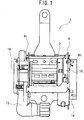
- Fig. 1 is a front view of the whole seatbelt retractor according to the invention
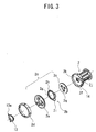
- Fig. 2 is an exploded perspective view explaining the assembling of a take-up drum 2, a connector 3, a housing 9, a torsion bar 4, a locking base 5, a base stopper 7, and so forth which constitute the major part of the seatbelt retractor illustrated in Fig. 1.
- the seatbelt retractor is provided with the substantially cylindrical take-up drum 2 on which webbing is wound.
- the torsion bar 4 is inserted through the center of the take-up drum 2, and one end of the torsion bar 4 is coupled integrally with one end of the take-up drum 2 by means of the connector 3, and it is supported by a pair of side plates (9b, 9c) to freely rotate.
- a spiral spring 19 (Fig. 1) is mounted on the side plate 9c, which constantly biases the take-up drum 2 to rotate in the take-up direction of the webbing, and the torsion bar 4 is biased to rotate in the take-up direction of the webbing.
- the seatbelt retractor in this embodiment has the structure which winds up slackness in the webbing by a gas pressure, and so forth in case of a vehicle emergency such as a collision, and restrains the movements of vehicle occupant by a pretensioner 15 (Fig. 1) furnished on the side plate 9c.
- the locking base 5 resembling a substantially disk-like shape is coupled integrally with the other end outside of the torsion bar 4 on the side of the side plate 9b of the housing, and it constitutes an emergency lock mechanism which restrains a rotation in the direction of the webbing pulled out.
- a clutch mechanism located near the other end of the torsion bar 4.
- a second energy-absorbing means is located on the other end of the torsion bar 4, close to the side on the other end of the take-up drum 2, wherein the torsion bar 4 (first energy-absorbing means) and the second energy-absorbing means perform the absorption of impact energy in case of a vehicle emergency.
- the housing 9 is made from a metal plate by a press-molding in a manner the right and left side plates (9b, 9c) rise up from both the sides of a back-plate fixed to the vehicle body, and the section of the housing forms a substantially U-letter.
- the left side plate 9c has an opening 9d formed, and the right side plate 9b has lock teeth 9a formed, while the torsion bar 4 assembled with the take-up drum 2 is bridged to freely rotate between the right and left side plates (9b, 9c), and the take-up drum 2 is continuously biased in the take-up direction of the webbing.
- the base stopper 7 is to prevent the locking base 5 from coming off from the take-up drum 2.
- the one end of the torsion bar 4 is engaged with a hole of the connector 3 having the same shape thereof, and the other end is coupled with the locking base 5 to be able to rotate integrally.
- the connector 3 is supported to freely rotate with the opening 9d bored on the side plate 9c of the housing 9, and it is also engaged with a hexagonal engagement recess being formed on the one end of the take-up drum 2 to correspond with the external shape of the connector 3, whereby the torsion bar 4 is capable of rotating integrally with the take-up drum 2.
- the emergency lock mechanism actuates the operation and the other end of the torsion bar 4 is fixed, the one end of the torsion bar 4 will rotate integrally with the take-up drum 2 by the webbing being pulled out. That is, the torsion bar 4 is twisted by the rotational force of the take-up drum 2, thus the energy of pulling out the webbing can be absorbed by the torsion resistance thereof.
- the torsion bar 4 functions as the first energy-absorbing means.
- Fig. 3 is an exploded perspective view explaining the assembling of a plate assembly 2e, which constitutes the second energy-absorbing means.
- the plate assembly 2e comprises a plate body 2a, a spiral wire 2b with plural winds, and a disk member 2c having plural projections 2q located circumferentially around a center hole.
- one end 2g of the wire is fixed to the plate body 2a, and the other end 2h of the wire is suspended to the backside of the disk member 2c (viewed from Fig. 3).
- Fig. 4 is an exploded perspective view illustrating the whole of the second energy-absorbing means.
- the plate assembly 2e and the take-up drum 2 are attached with a retainer 2d.
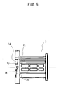
- Fig. 5 is a front view of the take-up drum 2, and the guide part of a deformable member guide part is made up with engagement pins 14, a curved path 2j, slopes 2t, and so forth.
- Fig. 6 is a side view of the plate assembly 2e
- Fig. 7 is a front view partly in section of the same, wherein the plate assembly 2e is assembled with the plate body 2a, the wire 2b, and the disk member 2c, as illustrated in Fig.3.
- a substantially circular receiving recess 2f which constitutes a part of the second energy-absorbing means is formed on the side where the locking base is mounted on the take-up drum 2, namely, on the end face of the left side in the drawing.
- an engagement hole 2k which receives a boss 5c (Fig. 2) of the locking base is formed on the center of the receiving recess 2f.
- the engagement pins 14 to be engaged with the wire 2b are formed at specified places on the periphery of the receiving recess 2f positioned outside the engagement hole 2k on the bottom face.
- the slopes 2t (Fig. 5) are formed at the specified places for engaging with the wire 2b.
- three semi-circular engagement pins 14 are formed integrally to project from the bottom face of the receiving recess 2f along the circumference thereof, wherein the wire 2b is formed in spiral, and the circumference 2i thereof is formed in curvature, which conforms to the circular sliding face of the engagement pins 14.
- Fig. 6 is a side view of the plate assembly 2e in which the individual components illustrated in Fig. 3 are assembled.
- the disk member 2c and the plate body 2a are engaged integrally with each other in a state where the spiral wire 2b is interposed between both.
- the plate body 2a and the disk member 2c form a take-up part 2m with a distance approximately equivalent to the diameter of the wire 2b, and the disk member 2c is coupled with the plate body 2a in a manner that a relative rotation between both is impossible.
- the curved one end 2g of the wire 2b is placed and fixed in a curved groove 2n (Fig. 7) of the plate body 2a.
- the wire 2b having the one end thereof fixed to the plate body 2a passes through the gap between the plate body 2a and the disk member 2c, and when the take-up drum 2 and the plate assembly 2e perform a relative rotation, the wire 2b reaches the upper face of the plate body 2a being the take-up part 2m.
- the disk member 2c covers take-up part 2m of the plate body 2a and the one end 2g of the wire 2b in the state where the plate assembly 2e is assembled.
- Fig. 7 is a front view which shows the internal structure of the plate assembly 2e, part of which is sectioned.
- the curved groove 2n is formed on the take-up part 2m of the plate body 2a by means of substantially semi-circular plural projections 2p, and the one end 2g of the wire 2b is placed in the curved groove 2n and is coupled therewith.
- the curvature radius of the curved groove 2n is formed smaller than that of the curved path 2j (Fig. 4) of the take-up drum 2.
- Fig. 8 illustrates another embodiment of the curved groove 2n.
- the plural projections 2p of the plate body 2a at least one set of ribs 2r facing to each other are formed between the projections 2p forming the curved groove 2n, and the gap between the ribs 2r is made narrower than the diameter of the wire 2b.
- Fig. 9 is a front view in section illustrating a state where the take-up drum 2 illustrated in Fig. 4 and the plate assembly 2e are assembled
- Fig. 10 is a partly cutaway side view of the assembly illustrated in Fig. 9.
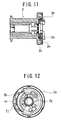
- Fig. 11 is a front view in section, illustrating a state where the take-up drum 2 rotates to a certain degree after the emergency lock mechanism actuates the operation in the assembly illustrated in Fig. 9, and
- Fig. 12 is a partly cutaway side view in the same state.
- the second energy-absorbing means having the above construction is contained in a space delimited between the take-up drum 2 and the locking base 5.
- the emergency lock mechanism actuates the operation, as the take-up drum 2 rotates, the wire 2b illustrated in Fig. 9 and Fig. 10 is wound into the take-up part 2m, as illustrated in Fig. 11 and Fig. 12.
- the wire 2b relatively moves between the disk member 2c and the plate body 2a, along the curved circumference 2i projected from the circumferential face of the disk member 2c, while sliding on the three semi-circular engagement pins 14 of the take-up drum 2.
- the emergency lock mechanism actuates the operation, in case of a vehicle emergency such as a collision, the locking base 5 coupled with the other end of the torsion bar 4 is blocked in rotating in the direction of the webbing pulled out. And, when a rotational torque more than a predetermined value acts on the take-up drum 2, due to the load acting on the webbing, the one end of the torsion bar 4 (first energy-absorbing means) actuates a torsional deformation.
- the take-up drum 2 rotates to a degree corresponding to the torsional deformation in the torsion bar 4, and at the same time, the other end of the torsion bar 4, which is fixed, rotates in the direction of the webbing pulled out, whereby the impact energy is absorbed.
- the actuation of the torsional deformation in the torsion bar 4 generates a relative rotation between the take-up drum 2 and the locking base 5.
- the absorption of the impact energy by the second energy-absorbing means actuates based on this relative rotation.
- the take-up drum 2 rotates relative to the locking base 5
- the plate body 2a to which the one end 2g of the wire 2b is fixed is coupled with the locking base 5, and it does not rotate, while since the engagement pins 14 formed integrally with the take-up drum 2 turn, the wire 2b is pulled between the engagement pins 14. That is, the wire 2b slides between the engagement pins 14 while being positioned by the slopes 2t, while being sequentially pulled to meander between the engagement pins 14.
- there generate a high sliding resistance and a bending resistance in the wire 2b and hence the sliding resistance and the bending resistance absorb the impact energy.
- both the torsion bar 4 (first energy-absorbing means) and the second energy-absorbing means operate as the energy-absorbing mechanism, and absorb the impact energy in case of a vehicle emergency.
- the clutch mechanism releases the engagement of the plate body 2a with the locking base 5 of the emergency lock mechanism, and puts the plate body 2a from the state of a relative rotation with the take-up drum 2 being possible into the state of a united rotation with the take-up drum 2 being possible with the locking base 5 detached.
- This clutch mechanism switches the first state where a relative rotation of the plate body 2a with the other end of the torsion bar 4 is impossible into the second state where a relative rotation of the plate body 2a with the other end of the torsion bar 4 is possible. It also comprises the clutch release mechanism which actuates the switching at an arbitrary timing after detecting a vehicle collision.
- the clutch mechanism comprises, as shown in Fig. 2, a joint plate 5b coupled with the emergency lock mechanism in a manner that a relative rotation is impossible, and three joint pawls 12 being pivoted to be turnable on the opposite side of the take-up drum 2 to the plate body 2a, which are in face contact with the joint plate 5b to turn outward.
- the joint pawl 12 is a bow-formed member, and a pin 12b, which is pivoted on the opposite side of the take-up drum 2 to the plate body 2a, is formed on the one end thereof, and the joint pawl 12 turns with the pin 12b as the center. Further, the joint pawl 12 has an inner projection 12a (Fig. 16) formed on the center of the inner wall.
- a pawl holder 13 in a sectional concave and circular form is provided in order to position and support the joint pawls 12.
- the pawl holder 13 is provided, on the circumference thereof in correspondence with the positions of the joint pawls 12, with nail-formed parts 13c each having ribs 13a formed thereon. Inwardly slant slopes 13b formed on the ribs 13a and the nail-formed parts 13c come into contact with the outer faces of the joint pawls 12. This contact and the resin spring functions to bias the joint pawls 12 continuously toward the axial center.
- the plate body 2a is provided with projections 2s which restrain the joint pawls 12 from turning relative to the plate body 2a immediately after the joint pawls 12 climb over the ribs 13a of the pawl holder 13, the joint pawls 12 are clamped by the rib backsides 13d of the pawl holder and the projections 2s of the plate body so that the joint pawls 12 are prevented from turning to the plate body 2a.
- Fig. 13 is an exploded perspective view explaining the assembling of a release ring 8, the housing 9, a casing 10, and so forth being the components for releasing the clutch.
- Fig. 14 is an enlarged exploded perspective view of the release ring 8, the casing 10, a piston 10a, a gas generator 10b, a gas generator holder 11, and so forth, which are illustrated in Fig. 13.
- the clutch release mechanism will be described with reference to Fig. 13 and Fig. 14.
- the release ring 8 is mounted to be rotatable on the casing 10 fixed to the side plate 9b of the housing on the other side of the torsion bar 4 (Fig. 2), which is located on the circumferences of the joint pawls 12.
- the clutch release mechanism is made up with the casing 10, the gas generator 10b which generates gas in a cylinder 10e at an arbitrary timing after detecting a vehicle collision, and the piston 10a, which is pressed and driven by the gas pressure in the cylinder, and presses the circumference of the release ring 8 to rotate the release ring 8.
- the gas generator 10b is attached to the casing 10 by the gas generator holder 11.
- the release ring 8 is provided with a contact 8b which comes in contact with the piston 10a, and three tapered parts 8a located with a uniform spacing on the circumference thereof.
- the casing 10 which holds the release ring 8 is provided with tapered projections 10d corresponding to the tapered parts 8a of the release ring 8 rotated.
- the piston 10a pressed and driven by the gas pressure comes in contact with the contact 8b formed on the circumference of the release ring 8, and hence the release ring 8 rotates.
- the tapered parts 8a of the release ring 8 are guided by the tapered projections 10d of the casing, and the release ring 8 retreats toward the take-up drum 2 (Fig. 1) and retreats from the circumferences of the joint pawls 12 (Fig. 2).
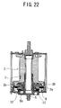
- Fig. 17 through Fig. 22 are partly cutaway side views and plan views in section, which explain the operation of the clutch mechanism.
- the clutch mechanism switches the first state where a relative rotation of the plate body 2a with the other end of the torsion bar 4 is impossible into the second state where a relative rotation of the plate body 2a with the other end of the torsion bar 4 is possible.
- the joint pawls 12 are biased toward the axial center by the slopes 13b (Fig. 15) formed on the ribs 13a of the pawl holder 13.
- the three joint pawls 12 are fixed at the most inwardly convergent position, in non-contact with the inner circumference of the release ring 8, and the inner projections 12a of the joint pawls 12 are in contact with projections 5d of the joint plate 5b.
- an engagement tooth 6b of a lock pawl 6 engages with the lock teeth 9a (Fig. 2) formed on the side plate 9b of the housing, thus generating a relative rotation between the joint plate 5b and the plate body 2a which will continue to rotate.
- a relative rotation is generated between the joint pawls 12 and the projections 5d of the joint plate, whereby the projections 5d of the joint plate press the inner projections 12a of the joint pawls 12, so that the joint pawls 12 receive a force toward the circumference, and they are prone to expand outwardly.
- the joint pawls 12 When the force exceeds the biasing force of the pawl holder 13, the joint pawls 12 come in contact with the inner-circumferential wall of the release ring 8. When the joint pawls 12 come in contact with the inner-circumferential wall of the release ring 8 and the outward expansion thereof is restrained, the locking base 5 and the plate body 2a become integrated with each other, and a relative rotation is generated between the take-up drum 2 and the plate body 2a, so that the wire 2b is pulled and the second energy absorption is performed, in addition to the energy absorption by the torsion bar 4.
- the piston 10a (Fig. 14) operates to rotate the release ring 8, whereby the rotation of the release ring 8 guides the tapered parts 8a of the release ring 8 to the tapered projections 10d of the casing (Fig. 14).
- the release ring 8 retreats toward the take-up drum 2, and retreats from the circumferences of the joint pawls 12 at the same time.
- the joint pawls 12 come in face contact with the joint plate 5b to expand outwardly, and become detached from the projections 5d of the joint plate, whereby the plate body 2a is released from the locking base 5.
- Fig. 23 is an exploded perspective view explaining the assembling of the emergency lock mechanism, which is made up with the locking base 5, a lock clutch 16, a cover 18, and so forth.
- Fig. 24 is an exploded perspective view explaining the assembling of the torsion bar 4, the lock pawl 6, the locking base 5, and so forth.
- a spring receiving part 16a is formed to project on one side of the lock clutch 16, and the spring receiving part 16a is engaged to be relatively movable with a play inside a spring containing part 5a resembling a recessed-groove shape, which is formed on the locking base 5.
- the spring receiving part 16a is elastically biased in a specified direction by a return spring 17 made of a coil spring retained in the spring containing part 5a, and the lock clutch 16 is made to rotate synchronously with the locking base 5 in a state of being biased in the direction of the webbing pulled out.
- the torsion bar 4 is inserted in a hole bored through the cylindrical boss 5c, which is formed to project from the side of the locking base 5 in the direction of facing the take-up drum 2, whereby, the torsion bar 4 is coupled with the locking base 5 to be rotatable integrally.
- the lock clutch 16 has a projected guide groove 16c formed thereon, and into the guide groove 16c, an interlocking pin 6a formed on the lock pawl 6 (Fig. 24) is slid and guided.
- the interlocking pin 6a is made to be slid and guided into the projected guide groove 16c by a relative rotation of the lock clutch 16 and the locking base 5 against the biasing force by the return spring 17. This sliding and guiding of the interlocking pin 6a makes it possible to freely project or retreat the engagement tooth 6b of the lock pawl 6 from the circumference of the locking base 5.
- the emergency lock mechanism is made up with the locking base 5, the lock pawl 6, the lock teeth 9a (Fig. 2) formed on the housing 9, the lock clutch 16, and so forth.
- a cover 18 is provided with a lock actuating mechanism which actuates the emergency lock mechanism in response to an abrupt pull-out of the webbing and an abrupt variation in the acceleration.
- the locking base 5 and the lock pawl 6 are attached with the joint plate 5b.
- the engagement tooth 6b is formed on a tip of the lock pawl 6, and the lock pawl 6 is located to be slidable on the locking base 5 by the interlocking pin 6a.
- the lock teeth 9a with which the engagement tooth 6b of the lock pawl 6 is able to engage are formed on the side plate 9b of the housing 9, and in case of a vehicle emergency, the engagement tooth 6b of the lock pawl 6 is engaged with the lock teeth 9a, and this engagement restrains the locking base 5 from rotating in the direction of the webbing pulled out.
- the second energy-absorbing means is contained in a space delimited by the take-up drum 2 and the locking base 5, there is not a substantial size expansion in the axial direction of the seatbelt retractor to sacrifice the compactification, although the second energy-absorbing means is provided separately from the torsion bar 4.
- the structures of the wire 2b and the engagement pins 14 which constitute the second energy-absorbing means are equally simple, and the manufacturing process thereof is rather simple as well.
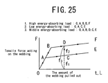
- Fig. 25 is a diagram illustrating the relation between a tensile force acting on the webbing and the amount of the webbing pulled out.
- the whole energy-absorbing load of the seatbelt retractor is the sum f3 of an energy-absorbing load f1 when the torsion bar 4 generates a torsional deformation and an energy-absorbing load f2 by the second energy-absorbing means, as illustrated in Fig. 25.
- the area of the energy absorption by the torsional deformation in the torsion bar 4 can be set freely independently.
- the area of the energy absorption by the second energy-absorbing means can be set to overlap a part of the area of the energy absorption by the torsional deformation in the torsion bar 4, thereby securing a high energy-absorbing load equivalent to the sum of both the energy-absorbing loads, in the part of the area of the energy absorption by the torsional deformation in the torsion bar 4.
- a low energy-absorbing load can be set only by the energy-absorbing function by the torsional deformation in the torsion bar 4.
- the adjustment of the whole energy-absorbing load of the seatbelt retractor is related to various factors such that it is related not only to the modifications of the diameter and material of the torsion bar 4, but also to the modifications of the size, shape, and material of the second energy-absorbing means.
- it is possible to realize a desired energy-absorbing load not depending on the modifications such as expansion of the diameter of the torsion bar 4 and modification of the material thereof, but by means of the design modification of the other remaining factors. That is, it is possible to easily set the energy-absorbing load high, without sacrificing the compactification of the seatbelt retractor by reducing the diameters of the torsion bar 4 and the take-up drum 2.
- both the torsion bar 4 and the second energy-absorbing means can be modified, by adjusting the energy-absorbing load and adjusting the energy-absorbing area in both the means, it becomes possible to easily meet the demand for a specific energy characteristic based on differences of the vehicle structure, and also possible to flexibly meet various needs.
- the adjustment of the sliding resistance between the wire 2b and the engagement pins 14 based on various factors such as a shape of the curved path, roughness of the contact faces of both, and size of the contact area and so forth.
- the adjustment of the sliding resistance is set based on various factors in this manner, for example, if a modification of part of the factors becomes difficult due to the restrictions of the dimensions, modifying the other factors will make it possible to adjust the sliding resistance comparably easily to an arbitrary value required.
- the lock actuating device actuates the emergency lock mechanism in case of a vehicle emergency, which restrains the other end of the torsion bar 4 from rotating in the direction of the webbing pulled out, and restrains the take-up drum 2 from rotating.
- the one end of the torsion bar 4 is coupled with the take-up drum 2 being driven to rotate in a manner that a relative rotation is impossible, and the other end thereof is coupled with the emergency lock mechanism which has restrained the rotation in a manner that a relative rotation is impossible, and hence the torsion bar 4 generates a torsional deformation, thereby rotating the take-up drum 2.
- the torsion bar 4 generates a torsional deformation, thereby rotating the take-up drum 2.
- the take-up drum 2 while the take-up drum 2 being rotating deforms the wire 2b, the one end of which is coupled with the take-up part 2m of the plate body 2a with the rotation restrained, at any time in the curved path 2j, the take-up drum 2 winds up the wire 2b into the take-up part 2m of the plate body 2a. At this moment, the wound-up wire 2b is positioned on an upper part in the circumferential direction of the take-up part 2m by a wire guide formed on a periphery of the take-up drum 2.
- the wire guide is formed on the curved path 2j, the wire 2b is positioned, while being deformed, on the upper part in the circumferential direction of the take-up part 2m.
- the disk member 2c and the plate body 2a are in parallel with each other along the circumferential direction of the take-up part 2m, and the wire 2b is wound up doubly trebly on the upper part in the circumferential direction of the take-up part 2m by the take-up drum 2, while being guided by both the members. Further, the disk member 2c prevents the wire 2b before deformation (side of the other end) and the wire 2b after deformation (side of the one end) from interfering each other.
- the wire 2b placed in the curved groove is firmly coupled therewith.
- the present invention is useful for a seatbelt retractor which absorbs an impact load acting on a vehicle occupant in case of a vehicle emergency such as a collision, and secures the vehicle occupant.
Abstract
Description
- The present invention relates to a seatbelt retractor provided with an energy-absorbing means, which, in case of a vehicle emergency, restrains a webbing from being pulled out to restrain movements of vehicle occupant and absorbs an impact load acting on the vehicle occupant.
- There has been known conventionally in the seatbelt retractor that has enhanced an energy-absorbing capability without sacrificing the compactification.
- As an example, there has been known a seatbelt apparatus provided with an energy-absorbing means, which has a wire engaged with a locking base and a bobbin (take-up drum) having a webbing wound thereon, and pulls the wire during a relative rotation between the locking base and the bobbin to thereby absorb the energy (JP 2002-53007A).
- In the conventional seatbelt apparatus, the wire is engaged so as to meander along an engagement pin, one end of which is attached to the locking base.
- Here in this case, since a part of the wire before being pulled by the engagement pin and a part of the wire after being pulled are set to be flush with a boss having the wire wound thereon, it is impossible to set the length of the wire sufficiently long, and accordingly impossible to extend the energy-absorbing time (EA). Since the engagement pin is attached to be flush with the boss, the spacing is narrow, and it is impossible to wind up the wire plural times in lamination.
- Therefore, an object of the present invention is to solve the above conventional problems.
- That is, the object is to increase the length of a deformable member (wire) by winding it up plural times in spiral, which makes it possible to extend the energy-absorbing time (EA) by both the members of a take-up shaft or a torsion bar and the deformable member, also makes it possible to expand the spacing in a take-up part of a plate body, and also makes it possible to wind up the deformable member (wire) plural times on an upper part in the circumferential direction of the take-up part.
- 1. A seatbelt retractor according to a first aspect of the invention comprises a take-up drum on which a webbing is wound, a torsion bar inserted through the take-up drum, one end of which is coupled with one end of the take-up drum in a manner that a relative rotation with the take-up drum is impossible, which is biased in the direction of the webbing taken up, an emergency lock mechanism located on the other end of the torsion bar, which restrains a rotation in the direction of the webbing pulled out, a lock actuating device which actuates the emergency lock mechanism in case of a vehicle emergency, a plate body having a take-up part on a side thereof being adjacent to a side on the other end of the take-up drum, which is coupled with the other end of the torsion bar in a manner that a relative rotation with the torsion bar is impossible, a deformable member, one end of which is coupled with the take-up part of the plate body, a part continued to the one end of which is located in a deformable member guide part formed on a periphery on the other end of the take-up drum, a part continued to the deformable member guide part which is wound up on and contained in a side different from a take-up side of the take-up part, which is wound up on the take-up part of the plate body by the take-up drum in case of a vehicle emergency, and a curved path on which a substantially medium part of the deformable member is located, which is formed on the periphery on the other end of the take-up drum.
- According to the first aspect of the invention, since the deformable member (wire) is positioned on an upper part in the circumferential direction of the take-up part, the components of the seatbelt retractor do not move after a vehicle emergency, and the positional relation of the components is held to be constant, and hence the components can be designed with simple structures. Since the side in the circumferential direction which contains the deformable member (wire) before deformation (the side on the other end) is different from the side on which the take-up part of the plate body is located, the deformable member (wire) can be provided longer, and the energy-absorbing time by both members of the torsion bar and the deformable member (wire) can be extended. Further, since the curved path is formed on the periphery of the take-up drum, a gap in the take-up part of the plate body can be made wider, and the deformable member (wire) can be wound up several times on the upper part in the circumferential direction of the take-up part.
- 2. A seatbelt retractor according to a second aspect of the invention is that, in the seatbelt retractor according to the first aspect of the invention, the deformable member is a wire, and the deformable member guide part is formed on the curved path.
- Thereby, the wire slides on the curved path formed on the periphery on the other end of the take-up drum, and it is continually positioned on the upper part in the circumferential direction of the take-up part by the deformable member guide part, thus, a stabilized energy absorption by the wire can be attained.
- 3. A seatbelt retractor according to a third aspect of the invention is that the seatbelt retractor according to the second aspect of the invention further comprises a disk member located between the take-up drum and the plate body, which is coupled with the plate body with a distance of the diameter of the wire from the plate body in a manner that a relative rotation with the plate body is impossible, and the disk member covers the take-up part of the plate body and the other end of the wire.
- Thereby, the wire wound up on the plate body is piled up regularly on one plane of the take-up part by the disk member without interference from the wire before deformation, thus, a stabilized energy absorption can be attained. Further, the wire before deformation is supplied regularly to the curved path of the take-up drum by the side on the other end of the take-up drum and the disk member, thus, a stabilized energy absorption can be attained.
- 4. A seatbelt retractor according to a fourth aspect of the invention is that, in the seatbelt retractor according to the third aspect of the invention, the wire attached to the take-up part of the plate body is located in a curved groove formed by plural projections, and the curvature radius of the curved groove is smaller than that of the curved path of the take-up drum.
- Thereby, the wire can be pulled out from the curved path of the take-up drum by merely the difference of the curvature radius, and the wire can be fixed easily without using another member for fixing.
- 5. A seatbelt retractor according to a fifth aspect of the invention is that, in the seatbelt retractor according to the third aspect of the invention, at least one set of ribs facing to each other are provided between the plural projections forming the curved groove in the plural projections of the plate body, and a gap between the ribs is narrower than the diameter of the wire.
- Thereby, the wire placed in the curved groove on the side of the plate body becomes difficult to come off in the vertical direction (in the axial direction of the torsion bar) from the side thereof, and the wire can be fixed more firmly, which stabilizes the initial setting in attaching. And, after attaching, carrying and assembling operations can be made easily.
- 6. A seatbelt retractor according to a sixth aspect of the invention is that, in the seatbelt retractor according to any one of the first through fifth aspects of the invention, a clutch mechanism is provided between the other end of the torsion bar and the plate body.
- Thereby, a load in the energy absorption can be reduced at an arbitrary level, and the energy absorption can be actuated under an optimum condition in correspondence with parameters such as physical make-up of vehicle occupant and scale of a vehicle collision.
-
- Fig. 1 is a front view of the whole seatbelt retractor according to the present invention;
- Fig. 2 is an exploded perspective view explaining the assembling of a housing, a take-up drum, a torsion bar, a locking base, a base stopper, and so forth of the seatbelt retractor illustrated in Fig. 1;
- Fig. 3 is an exploded perspective view explaining the assembling of a plate assembly;
- Fig. 4 is an exploded perspective view explaining the assembling of the plate assembly, a retainer, the take-up drum, and so forth;
- Fig. 5 is a front view of the take-up drum;
- Fig. 6 is a side view of the plate assembly;
- Fig. 7 is a front view partly in section of the plate assembly;
- Fig. 8 is a partly enlarged front view in section illustrating another embodiment of the plate assembly;
- Fig. 9 is a front view in section of an assembly in which the plate assembly and the take-up drum illustrated in Fig. 4 are assembled;
- Fig. 10 is a partly cutaway side view of the assembly illustrated in Fig. 9;
- Fig. 11 is a front view in section, in which the assembly illustrated in Fig. 9 is turned;
- Fig. 12 is a partly cutaway side view of the assembly illustrated in Fig. 11;
- Fig. 13 is an exploded perspective view explaining the assembling of a release ring, a housing, a casing, and so forth, which are illustrated in Fig. 2;
- Fig. 14 is an exploded perspective view of the release ring, the casing, a piston, a gas generator, a gas generator holder, and so forth;
- Fig. 15 is an enlarged perspective view of a pawl holder;
- Fig. 16 is an enlarged perspective view of a joint pawl;
- Fig. 17 is a partly cutaway side view of a clutch mechanism before actuating the operation;
- Fig. 18 is a plan view in section of the clutch mechanism illustrated in Fig. 17;
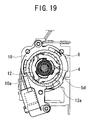
- Fig. 19 is a partly cutaway side view explaining a state where the clutch mechanism is engaged (first state);
- Fig. 20 is a plan view in section of the clutch mechanism illustrated in Fig. 19;
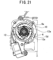
- Fig. 21 is a partly cutaway side view explaining a state where the clutch mechanism is released (second state);
- Fig. 22 is a plan view in section of the clutch mechanism illustrated in Fig. 21;
- Fig. 23 is an exploded perspective view explaining the assembling of the locking base, a lock clutch, a cover, and so forth;
- Fig. 24 is an exploded perspective view explaining the assembling of the torsion bar, the locking base, and so forth which are illustrated in Fig.2; and
- Fig. 25 is a diagram illustrating the relation between a tensile force acting on the webbing and the amount of the webbing pulled out.
-
- The preferred embodiment of the seatbelt retractor according to the present invention will be described in detail with reference to the accompanying drawings.
- Fig. 1 is a front view of the whole seatbelt retractor according to the invention, and Fig. 2 is an exploded perspective view explaining the assembling of a take-
up drum 2, aconnector 3, ahousing 9, atorsion bar 4, alocking base 5, abase stopper 7, and so forth which constitute the major part of the seatbelt retractor illustrated in Fig. 1. - In Fig. 2, the seatbelt retractor is provided with the substantially cylindrical take-up
drum 2 on which webbing is wound. Thetorsion bar 4 is inserted through the center of the take-up drum 2, and one end of thetorsion bar 4 is coupled integrally with one end of the take-up drum 2 by means of theconnector 3, and it is supported by a pair of side plates (9b, 9c) to freely rotate. A spiral spring 19 (Fig. 1) is mounted on theside plate 9c, which constantly biases the take-updrum 2 to rotate in the take-up direction of the webbing, and thetorsion bar 4 is biased to rotate in the take-up direction of the webbing. - Here, the seatbelt retractor in this embodiment has the structure which winds up slackness in the webbing by a gas pressure, and so forth in case of a vehicle emergency such as a collision, and restrains the movements of vehicle occupant by a pretensioner 15 (Fig. 1) furnished on the
side plate 9c. - The locking
base 5 resembling a substantially disk-like shape is coupled integrally with the other end outside of thetorsion bar 4 on the side of theside plate 9b of the housing, and it constitutes an emergency lock mechanism which restrains a rotation in the direction of the webbing pulled out. - A clutch mechanism, described later, is located near the other end of the
torsion bar 4. A second energy-absorbing means, described later, is located on the other end of thetorsion bar 4, close to the side on the other end of the take-up drum 2, wherein the torsion bar 4 (first energy-absorbing means) and the second energy-absorbing means perform the absorption of impact energy in case of a vehicle emergency. - The
housing 9 is made from a metal plate by a press-molding in a manner the right and left side plates (9b, 9c) rise up from both the sides of a back-plate fixed to the vehicle body, and the section of the housing forms a substantially U-letter. Theleft side plate 9c has anopening 9d formed, and theright side plate 9b haslock teeth 9a formed, while thetorsion bar 4 assembled with the take-up drum 2 is bridged to freely rotate between the right and left side plates (9b, 9c), and the take-up drum 2 is continuously biased in the take-up direction of the webbing. - The
base stopper 7 is to prevent thelocking base 5 from coming off from the take-up drum 2. First Energy-absorbing means - Next, the first energy-absorbing means will be described.
- As shown in Fig. 2, the one end of the
torsion bar 4 is engaged with a hole of theconnector 3 having the same shape thereof, and the other end is coupled with thelocking base 5 to be able to rotate integrally. - The
connector 3 is supported to freely rotate with theopening 9d bored on theside plate 9c of thehousing 9, and it is also engaged with a hexagonal engagement recess being formed on the one end of the take-up drum 2 to correspond with the external shape of theconnector 3, whereby thetorsion bar 4 is capable of rotating integrally with the take-up drum 2. - Therefore, even if the emergency lock mechanism actuates the operation and the other end of the
torsion bar 4 is fixed, the one end of thetorsion bar 4 will rotate integrally with the take-up drum 2 by the webbing being pulled out. That is, thetorsion bar 4 is twisted by the rotational force of the take-up drum 2, thus the energy of pulling out the webbing can be absorbed by the torsion resistance thereof. - In this manner, the
torsion bar 4 functions as the first energy-absorbing means. - Next, the second energy-absorbing means will be described with reference to Fig. 3 through Fig. 7.
- Fig. 3 is an exploded perspective view explaining the assembling of a
plate assembly 2e, which constitutes the second energy-absorbing means. Theplate assembly 2e comprises aplate body 2a, aspiral wire 2b with plural winds, and adisk member 2c havingplural projections 2q located circumferentially around a center hole. - In Fig. 3, one
end 2g of the wire is fixed to theplate body 2a, and theother end 2h of the wire is suspended to the backside of thedisk member 2c (viewed from Fig. 3). - Fig. 4 is an exploded perspective view illustrating the whole of the second energy-absorbing means. The
plate assembly 2e and the take-up drum 2 are attached with aretainer 2d. - Fig. 5 is a front view of the take-
up drum 2, and the guide part of a deformable member guide part is made up with engagement pins 14, acurved path 2j, slopes 2t, and so forth. - Fig. 6 is a side view of the
plate assembly 2e, and Fig. 7 is a front view partly in section of the same, wherein theplate assembly 2e is assembled with theplate body 2a, thewire 2b, and thedisk member 2c, as illustrated in Fig.3. - In Fig. 4, a substantially
circular receiving recess 2f which constitutes a part of the second energy-absorbing means is formed on the side where the locking base is mounted on the take-up drum 2, namely, on the end face of the left side in the drawing. Further, anengagement hole 2k which receives aboss 5c (Fig. 2) of the locking base is formed on the center of the receivingrecess 2f. The engagement pins 14 to be engaged with thewire 2b are formed at specified places on the periphery of the receivingrecess 2f positioned outside theengagement hole 2k on the bottom face. And, theslopes 2t (Fig. 5) are formed at the specified places for engaging with thewire 2b. In this case, three semi-circular engagement pins 14 are formed integrally to project from the bottom face of the receivingrecess 2f along the circumference thereof, wherein thewire 2b is formed in spiral, and thecircumference 2i thereof is formed in curvature, which conforms to the circular sliding face of the engagement pins 14. - Fig. 6 is a side view of the
plate assembly 2e in which the individual components illustrated in Fig. 3 are assembled. As illustrated in the drawing, thedisk member 2c and theplate body 2a are engaged integrally with each other in a state where thespiral wire 2b is interposed between both. Theplate body 2a and thedisk member 2c form a take-uppart 2m with a distance approximately equivalent to the diameter of thewire 2b, and thedisk member 2c is coupled with theplate body 2a in a manner that a relative rotation between both is impossible. Here, the curved oneend 2g of thewire 2b is placed and fixed in acurved groove 2n (Fig. 7) of theplate body 2a. - Thus, the
wire 2b having the one end thereof fixed to theplate body 2a passes through the gap between theplate body 2a and thedisk member 2c, and when the take-up drum 2 and theplate assembly 2e perform a relative rotation, thewire 2b reaches the upper face of theplate body 2a being the take-uppart 2m. - The
disk member 2c covers take-uppart 2m of theplate body 2a and the oneend 2g of thewire 2b in the state where theplate assembly 2e is assembled. - Fig. 7 is a front view which shows the internal structure of the
plate assembly 2e, part of which is sectioned. As illustrated in the drawing, thecurved groove 2n is formed on the take-uppart 2m of theplate body 2a by means of substantially semi-circularplural projections 2p, and the oneend 2g of thewire 2b is placed in thecurved groove 2n and is coupled therewith. The curvature radius of thecurved groove 2n is formed smaller than that of thecurved path 2j (Fig. 4) of the take-up drum 2. - Fig. 8 illustrates another embodiment of the
curved groove 2n. In theplural projections 2p of theplate body 2a, at least one set ofribs 2r facing to each other are formed between theprojections 2p forming thecurved groove 2n, and the gap between theribs 2r is made narrower than the diameter of thewire 2b. - Fig. 9 is a front view in section illustrating a state where the take-
up drum 2 illustrated in Fig. 4 and theplate assembly 2e are assembled, and Fig. 10 is a partly cutaway side view of the assembly illustrated in Fig. 9. Fig. 11 is a front view in section, illustrating a state where the take-up drum 2 rotates to a certain degree after the emergency lock mechanism actuates the operation in the assembly illustrated in Fig. 9, and Fig. 12 is a partly cutaway side view in the same state. - The second energy-absorbing means having the above construction is contained in a space delimited between the take-
up drum 2 and thelocking base 5. After the emergency lock mechanism actuates the operation, as the take-up drum 2 rotates, thewire 2b illustrated in Fig. 9 and Fig. 10 is wound into the take-uppart 2m, as illustrated in Fig. 11 and Fig. 12. - At this moment, the
wire 2b relatively moves between thedisk member 2c and theplate body 2a, along thecurved circumference 2i projected from the circumferential face of thedisk member 2c, while sliding on the three semi-circular engagement pins 14 of the take-up drum 2. - When the emergency lock mechanism actuates the operation, in case of a vehicle emergency such as a collision, the locking
base 5 coupled with the other end of thetorsion bar 4 is blocked in rotating in the direction of the webbing pulled out. And, when a rotational torque more than a predetermined value acts on the take-up drum 2, due to the load acting on the webbing, the one end of the torsion bar 4 (first energy-absorbing means) actuates a torsional deformation. - Thereby, the take-
up drum 2 rotates to a degree corresponding to the torsional deformation in thetorsion bar 4, and at the same time, the other end of thetorsion bar 4, which is fixed, rotates in the direction of the webbing pulled out, whereby the impact energy is absorbed. And, the actuation of the torsional deformation in thetorsion bar 4 generates a relative rotation between the take-up drum 2 and thelocking base 5. The absorption of the impact energy by the second energy-absorbing means actuates based on this relative rotation. - While the take-
up drum 2 rotates relative to thelocking base 5, theplate body 2a to which the oneend 2g of thewire 2b is fixed is coupled with thelocking base 5, and it does not rotate, while since the engagement pins 14 formed integrally with the take-up drum 2 turn, thewire 2b is pulled between the engagement pins 14. That is, thewire 2b slides between the engagement pins 14 while being positioned by theslopes 2t, while being sequentially pulled to meander between the engagement pins 14. At this moment, there generate a high sliding resistance and a bending resistance in thewire 2b, and hence the sliding resistance and the bending resistance absorb the impact energy. - That is, when the emergency lock mechanism actuates the operation in case of a vehicle emergency, and the load acting on the take-
up drum 2 in the direction of the webbing pulled out is increased more than a predetermined value, both the torsion bar 4 (first energy-absorbing means) and the second energy-absorbing means operate as the energy-absorbing mechanism, and absorb the impact energy in case of a vehicle emergency. - Next, the clutch mechanism will be described which releases the engagement of the
plate body 2a with thelocking base 5 of the emergency lock mechanism, and puts theplate body 2a from the state of a relative rotation with the take-up drum 2 being possible into the state of a united rotation with the take-up drum 2 being possible with thelocking base 5 detached. - This clutch mechanism switches the first state where a relative rotation of the
plate body 2a with the other end of thetorsion bar 4 is impossible into the second state where a relative rotation of theplate body 2a with the other end of thetorsion bar 4 is possible. It also comprises the clutch release mechanism which actuates the switching at an arbitrary timing after detecting a vehicle collision. - The clutch mechanism comprises, as shown in Fig. 2, a
joint plate 5b coupled with the emergency lock mechanism in a manner that a relative rotation is impossible, and threejoint pawls 12 being pivoted to be turnable on the opposite side of the take-up drum 2 to theplate body 2a, which are in face contact with thejoint plate 5b to turn outward. - The
joint pawl 12 is a bow-formed member, and apin 12b, which is pivoted on the opposite side of the take-up drum 2 to theplate body 2a, is formed on the one end thereof, and thejoint pawl 12 turns with thepin 12b as the center. Further, thejoint pawl 12 has aninner projection 12a (Fig. 16) formed on the center of the inner wall. - A pawl holder 13 (resin spring) in a sectional concave and circular form is provided in order to position and support the
joint pawls 12. Thepawl holder 13 is provided, on the circumference thereof in correspondence with the positions of thejoint pawls 12, with nail-formedparts 13c each havingribs 13a formed thereon. Inwardly slantslopes 13b formed on theribs 13a and the nail-formedparts 13c come into contact with the outer faces of thejoint pawls 12. This contact and the resin spring functions to bias thejoint pawls 12 continuously toward the axial center. - Meanwhile, as the
joint pawls 12 turn outward against the elasticity of the resin spring and climb over theribs 13a of thepawl holder 13, thepawl holder 13 is released from being pressed, the nail-formedparts 13c return to the insides of thejoint pawls 12, andrib backsides 13d of thepawl holder 13 come into contact withnotches 12c of thejoint pawls 12. On the other hand, since theplate body 2a is provided withprojections 2s which restrain thejoint pawls 12 from turning relative to theplate body 2a immediately after thejoint pawls 12 climb over theribs 13a of thepawl holder 13, thejoint pawls 12 are clamped by therib backsides 13d of the pawl holder and theprojections 2s of the plate body so that thejoint pawls 12 are prevented from turning to theplate body 2a. - Therefore, after the clutch is detached once, the clutch will not operate again. Clutch Release Mechanism
- Fig. 13 is an exploded perspective view explaining the assembling of a
release ring 8, thehousing 9, acasing 10, and so forth being the components for releasing the clutch. Fig. 14 is an enlarged exploded perspective view of therelease ring 8, thecasing 10, apiston 10a, agas generator 10b, agas generator holder 11, and so forth, which are illustrated in Fig. 13. - The clutch release mechanism will be described with reference to Fig. 13 and Fig. 14. The
release ring 8 is mounted to be rotatable on thecasing 10 fixed to theside plate 9b of the housing on the other side of the torsion bar 4 (Fig. 2), which is located on the circumferences of thejoint pawls 12. - As illustrated in Fig. 13 and Fig. 14, the clutch release mechanism is made up with the
casing 10, thegas generator 10b which generates gas in acylinder 10e at an arbitrary timing after detecting a vehicle collision, and thepiston 10a, which is pressed and driven by the gas pressure in the cylinder, and presses the circumference of therelease ring 8 to rotate therelease ring 8. Thegas generator 10b is attached to thecasing 10 by thegas generator holder 11. - The
release ring 8 is provided with acontact 8b which comes in contact with thepiston 10a, and three taperedparts 8a located with a uniform spacing on the circumference thereof. On the other hand, thecasing 10 which holds therelease ring 8 is provided withtapered projections 10d corresponding to the taperedparts 8a of therelease ring 8 rotated. - In the operation, the
piston 10a pressed and driven by the gas pressure comes in contact with thecontact 8b formed on the circumference of therelease ring 8, and hence therelease ring 8 rotates. Thereby, the taperedparts 8a of therelease ring 8 are guided by the taperedprojections 10d of the casing, and therelease ring 8 retreats toward the take-up drum 2 (Fig. 1) and retreats from the circumferences of the joint pawls 12 (Fig. 2). - Next, the operation of the clutch mechanism will be described based on Fig. 17 through Fig. 22.
- Fig. 17 through Fig. 22 are partly cutaway side views and plan views in section, which explain the operation of the clutch mechanism.
- In Fig. 17 through Fig. 22, as already described, the clutch mechanism switches the first state where a relative rotation of the
plate body 2a with the other end of thetorsion bar 4 is impossible into the second state where a relative rotation of theplate body 2a with the other end of thetorsion bar 4 is possible. - In the assembly state, the
joint pawls 12 are biased toward the axial center by theslopes 13b (Fig. 15) formed on theribs 13a of thepawl holder 13. The threejoint pawls 12 are fixed at the most inwardly convergent position, in non-contact with the inner circumference of therelease ring 8, and theinner projections 12a of thejoint pawls 12 are in contact withprojections 5d of thejoint plate 5b. - Here, as the emergency lock mechanism actuates the operation, an
engagement tooth 6b of a lock pawl 6 (Fig. 24) engages with thelock teeth 9a (Fig. 2) formed on theside plate 9b of the housing, thus generating a relative rotation between thejoint plate 5b and theplate body 2a which will continue to rotate. At this moment, a relative rotation is generated between thejoint pawls 12 and theprojections 5d of the joint plate, whereby theprojections 5d of the joint plate press theinner projections 12a of thejoint pawls 12, so that thejoint pawls 12 receive a force toward the circumference, and they are prone to expand outwardly. - When the force exceeds the biasing force of the
pawl holder 13, thejoint pawls 12 come in contact with the inner-circumferential wall of therelease ring 8. When thejoint pawls 12 come in contact with the inner-circumferential wall of therelease ring 8 and the outward expansion thereof is restrained, the lockingbase 5 and theplate body 2a become integrated with each other, and a relative rotation is generated between the take-up drum 2 and theplate body 2a, so that thewire 2b is pulled and the second energy absorption is performed, in addition to the energy absorption by thetorsion bar 4. - Next, as the clutch release mechanism actuates the operation in this state, the
piston 10a (Fig. 14) operates to rotate therelease ring 8, whereby the rotation of therelease ring 8 guides the taperedparts 8a of therelease ring 8 to the taperedprojections 10d of the casing (Fig. 14). Thus, therelease ring 8 retreats toward the take-up drum 2, and retreats from the circumferences of thejoint pawls 12 at the same time. - The
joint pawls 12 come in face contact with thejoint plate 5b to expand outwardly, and become detached from theprojections 5d of the joint plate, whereby theplate body 2a is released from the lockingbase 5. - That is, as the clutch mechanism actuates the operation to move the
release ring 8 in the axial direction, as illustrated in Fig. 21 and Fig. 22, thejoint pawls 12 expand outward, and theprojections 5d of the joint plate are completely detached from thejoint pawls 12, and hence the locked state where thelocking base 5 and theplate body 2a are integrally fixed is released. In consequence, the pull-out motion of thewire 2b is halted, and theplate body 2a and the take-up drum 2 become rotatable integrally. However, since the take-up drum 2 and thelocking base 5 continue a relative rotation even in this case, thetorsion bar 4 alone continues the energy absorption. Emergency Lock Mechanism - Fig. 23 is an exploded perspective view explaining the assembling of the emergency lock mechanism, which is made up with the
locking base 5, alock clutch 16, acover 18, and so forth. Fig. 24 is an exploded perspective view explaining the assembling of thetorsion bar 4, thelock pawl 6, the lockingbase 5, and so forth. - As a concrete construction of the emergency lock mechanism, various known ones may be adopted. As one example, as illustrated in Fig. 23 and Fig. 24, a
spring receiving part 16a is formed to project on one side of thelock clutch 16, and thespring receiving part 16a is engaged to be relatively movable with a play inside aspring containing part 5a resembling a recessed-groove shape, which is formed on thelocking base 5. - At this moment, the
spring receiving part 16a is elastically biased in a specified direction by areturn spring 17 made of a coil spring retained in thespring containing part 5a, and thelock clutch 16 is made to rotate synchronously with thelocking base 5 in a state of being biased in the direction of the webbing pulled out. - The
torsion bar 4 is inserted in a hole bored through thecylindrical boss 5c, which is formed to project from the side of thelocking base 5 in the direction of facing the take-up drum 2, whereby, thetorsion bar 4 is coupled with thelocking base 5 to be rotatable integrally. - The
lock clutch 16 has a projectedguide groove 16c formed thereon, and into theguide groove 16c, an interlockingpin 6a formed on the lock pawl 6 (Fig. 24) is slid and guided. The interlockingpin 6a is made to be slid and guided into the projectedguide groove 16c by a relative rotation of thelock clutch 16 and thelocking base 5 against the biasing force by thereturn spring 17. This sliding and guiding of the interlockingpin 6a makes it possible to freely project or retreat theengagement tooth 6b of thelock pawl 6 from the circumference of thelocking base 5. - The emergency lock mechanism is made up with the
locking base 5, thelock pawl 6, thelock teeth 9a (Fig. 2) formed on thehousing 9, thelock clutch 16, and so forth. - In order to actuate the emergency lock mechanism, a
cover 18 is provided with a lock actuating mechanism which actuates the emergency lock mechanism in response to an abrupt pull-out of the webbing and an abrupt variation in the acceleration. - The locking
base 5 and thelock pawl 6 are attached with thejoint plate 5b. - The
engagement tooth 6b is formed on a tip of thelock pawl 6, and thelock pawl 6 is located to be slidable on thelocking base 5 by the interlockingpin 6a. Thelock teeth 9a with which theengagement tooth 6b of thelock pawl 6 is able to engage are formed on theside plate 9b of thehousing 9, and in case of a vehicle emergency, theengagement tooth 6b of thelock pawl 6 is engaged with thelock teeth 9a, and this engagement restrains thelocking base 5 from rotating in the direction of the webbing pulled out. - According to the invention thus described, since the second energy-absorbing means is contained in a space delimited by the take-
up drum 2 and thelocking base 5, there is not a substantial size expansion in the axial direction of the seatbelt retractor to sacrifice the compactification, although the second energy-absorbing means is provided separately from thetorsion bar 4. - Further, the structures of the
wire 2b and the engagement pins 14 which constitute the second energy-absorbing means are equally simple, and the manufacturing process thereof is rather simple as well. - Fig. 25 is a diagram illustrating the relation between a tensile force acting on the webbing and the amount of the webbing pulled out.
- The whole energy-absorbing load of the seatbelt retractor is the sum f3 of an energy-absorbing load f1 when the
torsion bar 4 generates a torsional deformation and an energy-absorbing load f2 by the second energy-absorbing means, as illustrated in Fig. 25. - In case of a high energy-absorbing load, the relation between both forms a curve O, A, B, D, F in case of a low energy-absorbing load, it forms a curve O, A, C, E by the switching by the clutch mechanism, and, in case of a medium energy-absorbing load, it forms a curve O, A, B, D, C, E.
- Further, with regard to the area of the energy absorption by the torsional deformation in the
torsion bar 4, the area of the energy absorption by the sliding resistance of the second energy-absorbing means can be set freely independently. - For example, the area of the energy absorption by the second energy-absorbing means can be set to overlap a part of the area of the energy absorption by the torsional deformation in the
torsion bar 4, thereby securing a high energy-absorbing load equivalent to the sum of both the energy-absorbing loads, in the part of the area of the energy absorption by the torsional deformation in thetorsion bar 4. In the area where both the energy-absorbing areas do not overlap each other, a low energy-absorbing load can be set only by the energy-absorbing function by the torsional deformation in thetorsion bar 4. Thus, it is possible to provide the energy-absorbing mechanism of the seatbelt retractor with such an energy-absorbing characteristic in which the energy-absorbing load varies during the operation. - Further, the adjustment of the whole energy-absorbing load of the seatbelt retractor is related to various factors such that it is related not only to the modifications of the diameter and material of the
torsion bar 4, but also to the modifications of the size, shape, and material of the second energy-absorbing means. For example, it is possible to realize a desired energy-absorbing load, not depending on the modifications such as expansion of the diameter of thetorsion bar 4 and modification of the material thereof, but by means of the design modification of the other remaining factors. That is, it is possible to easily set the energy-absorbing load high, without sacrificing the compactification of the seatbelt retractor by reducing the diameters of thetorsion bar 4 and the take-up drum 2. And, in case that the size and the material of both thetorsion bar 4 and the second energy-absorbing means can be modified, by adjusting the energy-absorbing load and adjusting the energy-absorbing area in both the means, it becomes possible to easily meet the demand for a specific energy characteristic based on differences of the vehicle structure, and also possible to flexibly meet various needs. - Meanwhile, it is preferable to set the adjustment of the sliding resistance between the
wire 2b and the engagement pins 14 based on various factors such as a shape of the curved path, roughness of the contact faces of both, and size of the contact area and so forth. When the adjustment of the sliding resistance is set based on various factors in this manner, for example, if a modification of part of the factors becomes difficult due to the restrictions of the dimensions, modifying the other factors will make it possible to adjust the sliding resistance comparably easily to an arbitrary value required. - As described above, according to the seatbelt retractor of the present invention, the lock actuating device actuates the emergency lock mechanism in case of a vehicle emergency, which restrains the other end of the
torsion bar 4 from rotating in the direction of the webbing pulled out, and restrains the take-up drum 2 from rotating. At this moment, as the webbing is pulled out by a pull-out force more than a predetermined value, the one end of thetorsion bar 4 is coupled with the take-up drum 2 being driven to rotate in a manner that a relative rotation is impossible, and the other end thereof is coupled with the emergency lock mechanism which has restrained the rotation in a manner that a relative rotation is impossible, and hence thetorsion bar 4 generates a torsional deformation, thereby rotating the take-up drum 2. At the same time, there generates a relative rotation between the take-up drum 2 being rotating and theplate body 2a on the other end of thetorsion bar 4 with the rotation restrained. And, while the take-up drum 2 being rotating deforms thewire 2b, the one end of which is coupled with the take-uppart 2m of theplate body 2a with the rotation restrained, at any time in thecurved path 2j, the take-up drum 2 winds up thewire 2b into the take-uppart 2m of theplate body 2a. At this moment, the wound-upwire 2b is positioned on an upper part in the circumferential direction of the take-uppart 2m by a wire guide formed on a periphery of the take-up drum 2. - Since the wire guide is formed on the
curved path 2j, thewire 2b is positioned, while being deformed, on the upper part in the circumferential direction of the take-uppart 2m. - The
disk member 2c and theplate body 2a are in parallel with each other along the circumferential direction of the take-uppart 2m, and thewire 2b is wound up doubly trebly on the upper part in the circumferential direction of the take-uppart 2m by the take-up drum 2, while being guided by both the members. Further, thedisk member 2c prevents thewire 2b before deformation (side of the other end) and thewire 2b after deformation (side of the one end) from interfering each other. - Since the curvature radius of the
curved groove 2n on the take-uppart 2m is smaller than that of thecurved path 2j on the take-up drum 2, when the take-up drum 2 and theplate body 2a rotate relatively with each other, thewire 2b is pulled out from thecurved path 2j on the take-up drum 2. - Since at least one set of the
ribs 2r are formed in thecurved groove 2n formed by theplural projections 2p, and the gap between theribs 2r is narrower than the diameter of thewire 2b, thewire 2b placed in the curved groove is firmly coupled therewith. - On the way of the energy absorption by the
torsion bar 4 and thewire 2b, since the clutch mechanism puts theplate body 2a into a state of a relative rotation being possible with the other end of thetorsion bar 4, it is possible to discontinue the deformation of thewire 2b at an arbitrary timing. - The present invention is useful for a seatbelt retractor which absorbs an impact load acting on a vehicle occupant in case of a vehicle emergency such as a collision, and secures the vehicle occupant.
Claims (6)
- A seatbelt retractor comprises:a take-up drum on which a webbing is wound;a torsion bar inserted through the take-up drum, one end of which is coupled with one end of the take-up drum in a manner that a relative rotation with the take-up drum is impossible, which is biased in the direction of the webbing taken up;an emergency lock mechanism located on the other end of the torsion bar, which restrains a rotation in the direction of the webbing pulled out;a lock actuating device which actuates the emergency lock mechanism in case of a vehicle emergency;a plate body having a take-up part on a side thereof being adjacent to a side on the other end of the take-up drum, which is coupled with the other end of the torsion bar in a manner that a relative rotation with the torsion bar is impossible;a deformable member, one end of which is coupled with the take-up part of the plate body, a part continued to the one end of which is located in a deformable member guide part formed on a periphery on the other end of the take-up drum, a part continued to the deformable member guide part which is wound up on and contained in a side different from a take-up side of the take-up part, which is wound up on the take-up part of the plate body by the take-up drum in case of a vehicle emergency; anda curved path on which a substantially medium part of the deformable member is located, which is formed on the periphery on the other end of the take-up drum.
- A seatbelt retractor according to Claim 1, wherein the deformable member is a wire, and the deformable member guide part is formed on the curved path.
- A seatbelt retractor according to Claim 2, further comprising a disk member located between the take-up drum and the plate body, which is coupled with the plate body with a distance of the diameter of the wire from the plate body in a manner that a relative rotation with the plate body is impossible, and the disk member covers the take-up part of the plate body and the other end of the wire.
- A seatbelt retractor according to Claim 2 or 3, wherein the wire attached to the take-up part of the plate body is located in a curved groove formed by plural projections, and the curvature radius of the curved groove is smaller than that of the curved path of the take-up drum.
- A seatbelt retractor according to Claim 4, wherein at least one set of ribs facing to each other are provided between the plural projections forming the curved groove in the plural projections of the plate body, and a gap between the ribs is narrower than the diameter of the wire.
- A seatbelt retractor according to any of Claims 1 to 5, wherein a clutch mechanism is provided between the other end of the torsion bar and the plate body.
Priority Applications (1)
| Application Number | Priority Date | Filing Date | Title |
|---|---|---|---|
| EP06018564A EP1738975B1 (en) | 2003-01-31 | 2004-01-29 | Seatbelt retractor |
Applications Claiming Priority (3)
| Application Number | Priority Date | Filing Date | Title |
|---|---|---|---|
| JP2003024786 | 2003-01-31 | ||
| JP2003024786A JP4166096B2 (en) | 2003-01-31 | 2003-01-31 | Seat belt retractor |
| PCT/JP2004/000796 WO2004067339A1 (en) | 2003-01-31 | 2004-01-29 | Seat-belt retractor |
Related Child Applications (1)
| Application Number | Title | Priority Date | Filing Date |
|---|---|---|---|
| EP06018564A Division EP1738975B1 (en) | 2003-01-31 | 2004-01-29 | Seatbelt retractor |
Publications (3)
| Publication Number | Publication Date |
|---|---|
| EP1595758A1 true EP1595758A1 (en) | 2005-11-16 |
| EP1595758A4 EP1595758A4 (en) | 2006-02-15 |
| EP1595758B1 EP1595758B1 (en) | 2007-03-14 |
Family
ID=32820775
Family Applications (2)
| Application Number | Title | Priority Date | Filing Date |
|---|---|---|---|
| EP04706287A Expired - Fee Related EP1595758B1 (en) | 2003-01-31 | 2004-01-29 | Seat-belt retractor |
| EP06018564A Expired - Fee Related EP1738975B1 (en) | 2003-01-31 | 2004-01-29 | Seatbelt retractor |
Family Applications After (1)
| Application Number | Title | Priority Date | Filing Date |
|---|---|---|---|
| EP06018564A Expired - Fee Related EP1738975B1 (en) | 2003-01-31 | 2004-01-29 | Seatbelt retractor |
Country Status (6)
| Country | Link |
|---|---|
| US (1) | US7753305B2 (en) |
| EP (2) | EP1595758B1 (en) |
| JP (1) | JP4166096B2 (en) |
| KR (1) | KR100993576B1 (en) |
| DE (2) | DE602004005315T2 (en) |
| WO (1) | WO2004067339A1 (en) |
Cited By (3)
| Publication number | Priority date | Publication date | Assignee | Title |
|---|---|---|---|---|
| WO2009138173A1 (en) * | 2008-05-16 | 2009-11-19 | Autoliv Development Ab | Self-locking belt retractor |
| WO2019072539A1 (en) * | 2017-10-13 | 2019-04-18 | Trw Automotive Gmbh | Seat belt retractor |
| WO2020055354A3 (en) * | 2018-07-15 | 2020-06-04 | Alupam Ileri Teknolojik Malzeme A.S | Impact dampening system for seat belt |
Families Citing this family (11)
| Publication number | Priority date | Publication date | Assignee | Title |
|---|---|---|---|---|
| GB0315844D0 (en) * | 2003-07-04 | 2003-08-13 | Transitive Ltd | Method and apparatus for performing adjustable precision exception handling |
| US7641139B2 (en) * | 2006-08-18 | 2010-01-05 | Delphi Technologies, Inc. | Clutch device for seatbelt retractor |
| KR100944879B1 (en) * | 2008-05-29 | 2010-03-03 | 쌍용자동차 주식회사 | Mounting structure of seat belt for automobile |
| US20100213302A1 (en) * | 2009-02-26 | 2010-08-26 | Tk Holdings Inc. | Retractor assembly |
| DE102014114140B4 (en) * | 2014-09-29 | 2017-01-05 | Autoliv Development Ab | Belt retractor with two-part tensioner wheel |
| JP6498506B2 (en) * | 2015-04-24 | 2019-04-10 | 株式会社東海理化電機製作所 | Webbing take-up device |
| JP2016203844A (en) * | 2015-04-24 | 2016-12-08 | 株式会社東海理化電機製作所 | Webbing rewinding device |
| JP6498507B2 (en) * | 2015-04-24 | 2019-04-10 | 株式会社東海理化電機製作所 | Webbing take-up device |
| US20180154861A1 (en) * | 2015-04-24 | 2018-06-07 | Kabushiki Kaisha Tokai-Rika-Denki-Seisakusho | Webbing take-up device |
| JP6306537B2 (en) | 2015-05-29 | 2018-04-04 | 株式会社東海理化電機製作所 | Webbing take-up device |
| DE102017111398A1 (en) * | 2017-05-24 | 2018-11-29 | Trw Automotive Gmbh | Belt retractor and method for controlling a belt retractor |
Citations (2)
| Publication number | Priority date | Publication date | Assignee | Title |
|---|---|---|---|---|
| US20020017583A1 (en) * | 2000-05-02 | 2002-02-14 | Hideaki Yano | Seat belt retractor |
| DE20210812U1 (en) * | 2002-07-17 | 2002-11-21 | Trw Repa Gmbh | Belt retractor with force limiting function |
Family Cites Families (23)
| Publication number | Priority date | Publication date | Assignee | Title |
|---|---|---|---|---|
| DE1935539C2 (en) * | 1969-07-12 | 1984-10-25 | Adam Opel AG, 6090 Rüsselsheim | Force limiters for seat belts |
| JPS5619245U (en) * | 1979-07-19 | 1981-02-20 | ||
| US5607118A (en) * | 1995-08-11 | 1997-03-04 | Alliedsignal Inc. | Retractor with adjustable load limiting levels |
| JP3709231B2 (en) | 1996-01-24 | 2005-10-26 | 株式会社東海理化電機製作所 | Webbing take-up device |
| JPH09286302A (en) | 1996-04-23 | 1997-11-04 | Nippon Seiko Kk | Seat belt retractor |
| BR9709962A (en) * | 1996-06-26 | 1999-08-10 | Autoliv Dev | Strap reel device with adjustable force limiting device |
| JPH10100860A (en) | 1996-09-26 | 1998-04-21 | Suncall Corp | Damper for automobile seat belt |
| US5823570A (en) * | 1996-10-10 | 1998-10-20 | Trw Vehicle Safety Systems Inc. | Seat belt retractor with energy management |
| DE19733787C1 (en) * | 1997-08-05 | 1998-12-03 | Daimler Benz Ag | Belt roller for motor vehicle safety belt |
| DE29718663U1 (en) * | 1997-10-21 | 1998-02-19 | Trw Repa Gmbh | Force limited in a seat belt restraint system |
| DE29816280U1 (en) * | 1998-09-10 | 1999-01-21 | Trw Repa Gmbh | Force limiting device |
| DE19856364A1 (en) * | 1998-12-07 | 2000-06-08 | Trw Repa Gmbh | Belt retractor for a vehicle seat belt |
| DE29821801U1 (en) * | 1998-12-07 | 1999-04-08 | Trw Repa Gmbh | Belt retractor for a vehicle seat belt |
| DE19927427C2 (en) | 1999-06-16 | 2002-11-14 | Autoliv Dev | Belt retractor with switchable force limiter |
| JP2001055115A (en) | 1999-08-20 | 2001-02-27 | Takata Corp | Rotary coupling device and seat belt retractor using thereof |
| JP4526631B2 (en) | 2000-01-24 | 2010-08-18 | オートリブ株式会社 | Seat belt device |
| JP2001287621A (en) | 2000-04-07 | 2001-10-16 | Tokai Rika Co Ltd | Device for winding webbing |
| JP2001301569A (en) | 2000-04-24 | 2001-10-31 | Tokai Rika Co Ltd | Webbing winding device and vehicle |
| JP3723423B2 (en) | 2000-05-31 | 2005-12-07 | エヌエスケー・オートリブ株式会社 | Seat belt device |
| JP4323081B2 (en) * | 2000-10-26 | 2009-09-02 | 株式会社東海理化電機製作所 | Webbing take-up device |
| GB2387574B (en) * | 2002-04-16 | 2004-05-19 | Breed Automotive Tech | Retractor |
| GB2387576B (en) * | 2002-04-16 | 2004-04-14 | Breed Automotive Tech | Retractor |
| US6969022B2 (en) * | 2003-10-14 | 2005-11-29 | Key Safety Systems, Inc. | Seat belt retractor |
-
2003
- 2003-01-31 JP JP2003024786A patent/JP4166096B2/en not_active Expired - Fee Related
-
2004
- 2004-01-29 KR KR1020057013388A patent/KR100993576B1/en active IP Right Grant
- 2004-01-29 EP EP04706287A patent/EP1595758B1/en not_active Expired - Fee Related
- 2004-01-29 US US10/543,894 patent/US7753305B2/en not_active Expired - Fee Related
- 2004-01-29 WO PCT/JP2004/000796 patent/WO2004067339A1/en active IP Right Grant
- 2004-01-29 EP EP06018564A patent/EP1738975B1/en not_active Expired - Fee Related
- 2004-01-29 DE DE602004005315T patent/DE602004005315T2/en not_active Expired - Lifetime
- 2004-01-29 DE DE602004009838T patent/DE602004009838T2/en not_active Expired - Lifetime
Patent Citations (2)
| Publication number | Priority date | Publication date | Assignee | Title |
|---|---|---|---|---|
| US20020017583A1 (en) * | 2000-05-02 | 2002-02-14 | Hideaki Yano | Seat belt retractor |
| DE20210812U1 (en) * | 2002-07-17 | 2002-11-21 | Trw Repa Gmbh | Belt retractor with force limiting function |
Non-Patent Citations (1)
| Title |
|---|
| See also references of WO2004067339A1 * |
Cited By (3)
| Publication number | Priority date | Publication date | Assignee | Title |
|---|---|---|---|---|
| WO2009138173A1 (en) * | 2008-05-16 | 2009-11-19 | Autoliv Development Ab | Self-locking belt retractor |
| WO2019072539A1 (en) * | 2017-10-13 | 2019-04-18 | Trw Automotive Gmbh | Seat belt retractor |
| WO2020055354A3 (en) * | 2018-07-15 | 2020-06-04 | Alupam Ileri Teknolojik Malzeme A.S | Impact dampening system for seat belt |
Also Published As
| Publication number | Publication date |
|---|---|
| JP2004262263A (en) | 2004-09-24 |
| EP1738975A1 (en) | 2007-01-03 |
| WO2004067339A1 (en) | 2004-08-12 |
| US20060219832A1 (en) | 2006-10-05 |
| KR100993576B1 (en) | 2010-11-10 |
| EP1595758B1 (en) | 2007-03-14 |
| EP1738975B1 (en) | 2007-10-31 |
| DE602004005315D1 (en) | 2007-04-26 |
| EP1595758A4 (en) | 2006-02-15 |
| KR20060034206A (en) | 2006-04-21 |
| DE602004005315T2 (en) | 2007-12-20 |
| DE602004009838D1 (en) | 2007-12-13 |
| DE602004009838T2 (en) | 2008-02-07 |
| US7753305B2 (en) | 2010-07-13 |
| JP4166096B2 (en) | 2008-10-15 |
Similar Documents
| Publication | Publication Date | Title |
|---|---|---|
| EP1595758B1 (en) | Seat-belt retractor | |
| US6354528B1 (en) | Webbing retractor | |
| US7942361B2 (en) | Webbing retracting device | |
| JP4917395B2 (en) | Webbing take-up device | |
| US20050139712A1 (en) | Belt retractor for a vehicle safety belt | |
| EP1600342B1 (en) | Seat belt retractor | |
| JP4976241B2 (en) | Seat belt retractor and seat belt device using the same | |
| US8448889B2 (en) | Webbing take-up device | |
| EP1992531A2 (en) | Locking member mounting structure of seat belt retractor | |
| US7124974B2 (en) | Seat belt retractor | |
| US20080203808A1 (en) | Seat belt retractor and seat belt apparatus employing the same | |
| JP6176719B2 (en) | Seat belt retractor and seat belt device including the same | |
| US20080203807A1 (en) | Seat belt retractor and seat belt apparatus employing the same | |
| US9205773B2 (en) | Webbing take-up device | |
| US20120111986A1 (en) | Seat belt retractor and method for assembling spindle of seat belt retractor | |
| KR20060011480A (en) | Pretensioner of retractor for a seat belt | |
| JP2013049401A (en) | Webbing winder | |
| US20170291574A1 (en) | Pretensioner, seat belt retractor, and seat belt apparatus provided with the seat belt retractor | |
| WO2023112614A1 (en) | Webbing winding device | |
| KR200366953Y1 (en) | Pretensioner of retractor for a seat belt | |
| WO2018142872A1 (en) | Transmission mechanism | |
| JP2018111398A (en) | Webbing winding device |
Legal Events
| Date | Code | Title | Description |
|---|---|---|---|
| PUAI | Public reference made under article 153(3) epc to a published international application that has entered the european phase |
Free format text: ORIGINAL CODE: 0009012 |
|
| 17P | Request for examination filed |
Effective date: 20050825 |
|
| AK | Designated contracting states |
Kind code of ref document: A1 Designated state(s): AT BE BG CH CY CZ DE DK EE ES FI FR GB GR HU IE IT LI LU MC NL PT RO SE SI SK TR |
|
| AX | Request for extension of the european patent |
Extension state: AL LT LV MK |
|
| A4 | Supplementary search report drawn up and despatched |
Effective date: 20060102 |
|
| DAX | Request for extension of the european patent (deleted) | ||
| RBV | Designated contracting states (corrected) |
Designated state(s): DE FR GB |
|
| GRAP | Despatch of communication of intention to grant a patent |
Free format text: ORIGINAL CODE: EPIDOSNIGR1 |
|
| GRAS | Grant fee paid |
Free format text: ORIGINAL CODE: EPIDOSNIGR3 |
|
| GRAA | (expected) grant |
Free format text: ORIGINAL CODE: 0009210 |
|
| AK | Designated contracting states |
Kind code of ref document: B1 Designated state(s): DE FR GB |
|
| REG | Reference to a national code |
Ref country code: GB Ref legal event code: FG4D |
|
| REF | Corresponds to: |
Ref document number: 602004005315 Country of ref document: DE Date of ref document: 20070426 Kind code of ref document: P |
|
| ET | Fr: translation filed | ||
| PLBE | No opposition filed within time limit |
Free format text: ORIGINAL CODE: 0009261 |
|
| STAA | Information on the status of an ep patent application or granted ep patent |
Free format text: STATUS: NO OPPOSITION FILED WITHIN TIME LIMIT |
|
| 26N | No opposition filed |
Effective date: 20071217 |
|
| PGFP | Annual fee paid to national office [announced via postgrant information from national office to epo] |
Ref country code: FR Payment date: 20120202 Year of fee payment: 9 |
|
| PGFP | Annual fee paid to national office [announced via postgrant information from national office to epo] |
Ref country code: GB Payment date: 20120125 Year of fee payment: 9 |
|
| GBPC | Gb: european patent ceased through non-payment of renewal fee |
Effective date: 20130129 |
|
| REG | Reference to a national code |
Ref country code: FR Ref legal event code: ST Effective date: 20130930 |
|
| PG25 | Lapsed in a contracting state [announced via postgrant information from national office to epo] |
Ref country code: GB Free format text: LAPSE BECAUSE OF NON-PAYMENT OF DUE FEES Effective date: 20130129 Ref country code: FR Free format text: LAPSE BECAUSE OF NON-PAYMENT OF DUE FEES Effective date: 20130131 |
|
| PGFP | Annual fee paid to national office [announced via postgrant information from national office to epo] |
Ref country code: DE Payment date: 20140122 Year of fee payment: 11 |
|
| REG | Reference to a national code |
Ref country code: DE Ref legal event code: R119 Ref document number: 602004005315 Country of ref document: DE |
|
| PG25 | Lapsed in a contracting state [announced via postgrant information from national office to epo] |
Ref country code: DE Free format text: LAPSE BECAUSE OF NON-PAYMENT OF DUE FEES Effective date: 20150801 |