EP1595649B1 - Rotary impact tool - Google Patents
Rotary impact tool Download PDFInfo
- Publication number
- EP1595649B1 EP1595649B1 EP05252923A EP05252923A EP1595649B1 EP 1595649 B1 EP1595649 B1 EP 1595649B1 EP 05252923 A EP05252923 A EP 05252923A EP 05252923 A EP05252923 A EP 05252923A EP 1595649 B1 EP1595649 B1 EP 1595649B1
- Authority
- EP
- European Patent Office
- Prior art keywords
- fastening
- torque
- tight
- motor
- impact
- Prior art date
- Legal status (The legal status is an assumption and is not a legal conclusion. Google has not performed a legal analysis and makes no representation as to the accuracy of the status listed.)
- Not-in-force
Links
Images


Classifications
-
- B—PERFORMING OPERATIONS; TRANSPORTING
- B25—HAND TOOLS; PORTABLE POWER-DRIVEN TOOLS; MANIPULATORS
- B25B—TOOLS OR BENCH DEVICES NOT OTHERWISE PROVIDED FOR, FOR FASTENING, CONNECTING, DISENGAGING OR HOLDING
- B25B21/00—Portable power-driven screw or nut setting or loosening tools; Attachments for drilling apparatus serving the same purpose
- B25B21/02—Portable power-driven screw or nut setting or loosening tools; Attachments for drilling apparatus serving the same purpose with means for imparting impact to screwdriver blade or nut socket
-
- B—PERFORMING OPERATIONS; TRANSPORTING
- B25—HAND TOOLS; PORTABLE POWER-DRIVEN TOOLS; MANIPULATORS
- B25B—TOOLS OR BENCH DEVICES NOT OTHERWISE PROVIDED FOR, FOR FASTENING, CONNECTING, DISENGAGING OR HOLDING
- B25B23/00—Details of, or accessories for, spanners, wrenches, screwdrivers
- B25B23/14—Arrangement of torque limiters or torque indicators in wrenches or screwdrivers
- B25B23/1405—Arrangement of torque limiters or torque indicators in wrenches or screwdrivers for impact wrenches or screwdrivers
Definitions
- the present invention relates to a rotary impact tool such as an impact wrench or an impact driver used for fastening or loosening of fastening member such as a screw, a bolt or a nut.
- a rotary impact tool such as an impact wrench or an impact driver used for fastening or loosening of fastening member such as a screw, a bolt or a nut.
- fastening member such as a screw, a bolt or a nut.
- a tool is known from EP 1207016 A2 .
- a rotary impact tool which can stop the driving of the motor automatically when a fastening torque reaches to a predetermined value is conventionally provided.
- the fastening torque of the fastening member is insufficient for preventing the over fastening.
- Japanese Laid-Open Patent Publication No. 2001-129767 shows a rotary impact tool which can fasten the fastening member a little more further to stop the fastening of the fastening member in normal fastening torque (it is called tight fastening mode).
- the tight fastening mode cannot be transitive when the switching on state of the main switch after stopping the driving of the motor is maintained. Thus, if the user judges that the fastening of the fastening member is completed due to stop of the driving of the motor, the tight fastening mode cannot be transitive.
- a purpose of the present invention is to provide a rotary impact tool, which can perform the tight fastening operation independently from the normal fastening operation, continuously.
- a rotary impact tool in accordance with an aspect of the present invention is recited in Claim 1.
- the rotary impact tool comprises: a rotary driving mechanism including a motor for rotating a driving shaft; a hammer engaged with the driving shaft; an output shaft to which a driving force is applied by impact blow of the hammer; a main switch operated by a user for controlling fastening operation; a torque setting switch used by a user for setting a fastening torque; a torque calculator for calculating a fastening torque; and a controller for controlling on and off of the motor based on switching on and off of the main switch, an output of the torque calculator and the fastening torque set in the torque setting switch, and having a normal fastening mode and a tight fastening mode.
- the rotary impact tool further comprises a tight fastening mode setting switch used for setting the tight fastening mode.
- the controller continuously drives the rotary driving mechanism so as to perform tight fastening operation continuously.
- the rotary impact tool can perform the tight fastening operations continuously when the tight fastening mode setting switch is switched on. Therefore, it is possible that all the fastening members are fastened in normal fastening mode, and the tight fastening is continuously performed to the fastening members.
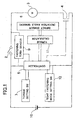
- the rotary impact tool comprises a main switch 2 used for controlling the fastening operation, a motor 3, a switching device 4 used for on and off of driving the motor 3, a controller (control circuit) 5, an impact sensor 6 which further serves as a rotation angle sensor, a torque setting switch 7 used for setting a fastening torque, a fastening term sensor (sensing circuit) 9, a battery 10 as a power source, a torque calculator (calculating circuit) 11 and a tight fastening mode setting switch 12.
- the battery 10, the main switch 2, the motor 3 and the switching device 4 are connected in series, and the series circuit is connected in parallel with the controller 5.
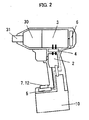
- FIG. 2 shows schematic configuration of the rotary impact tool
- FIG. 3 shown specific example of a driving mechanism 30 for performing fastening operation of a fastening member such as a screw, a bolt or a nut by impact blow.
- a reducer is configured by a sun gear 34, a pair of planet gears 32, and an internal gear 33.
- Rotation shafts 35 of the planet gears 32 are borne on a driving shaft 36.
- Rotation force of the motor 3 is transmitted to the driving shaft 36 via the reducer.
- a hammer 40 is engaged with an outer face of the driving shaft 36 via ball bearings 38 and a cam 39.
- a spring 37 is further provided between the driving shaft 36 and the hammer 40 for pressing the hammer 40 forward.
- the hammer 40 further has at least one engaging portion engaging with an anvil provided on an output shaft 31.
- the hammer 40 and the output shaft 31 are integrally rotated by the driving force of the motor 3.
- a load equal to or larger than a predetermined value is applied to the output shaft 31, the hammer moves backward against the pressing force of the spring 37.
- the engagement of the hammer 40 with the anvil of the output shaft 31 is released, the hammer 40 moves forward with rotation and applies impact blow in the rotation direction to the anvil of the output shaft 31, so that the output shaft 31 can be rotated.
- the impact sensor 6 senses not only the occurrence of the impact blow of the hammer 40 with the anvil of the output shaft 31, but also a rotation angle of the anvil or the output shaft 31 in each impact blow of the hammer 40.
- the impact sensor 6 it is possible to include a rotary encoder provided on the motor 3 for sensing the rotation of the shaft of the motor 3.
- a rotary encoder a frequency generator, a magnetic rotary encode or an optical rotary encoder can be used.
- the frequency generator has a magnetized disc fixed on the shaft of the motor, and senses the rotation of the disc with a coil.
- the magnetic rotary encoder has a magnetized disc fixed on the shaft of the motor, and senses the rotation of the disc with a hall IC.
- the optical rotary encoder has a disc with slits fixed on the shaft of the motor, and senses the rotation of the disc with a photo-coupler. Output signal from the rotation encoder is processed the waveform shaping of pulse width signal corresponding to the rotation speed of the motor 3 through a waveform shaping circuit (not shown), and transmitted to the impact sensor 6.
- the impact sensor 6 senses the occurrence of the impact blow of the hammer 40 utilizing a phenomenon that the pulse width of output of the rotation encoder becomes slightly longer.
- the impact sensor 6, however, is not limited to this configuration. It is possible to sense the occurrence of the impact blow with using blow sound gathered with a microphone or with using an acceleration sensor.
- the torque calculator 11 calculates the fastening torque T 1 based on a number N of impact blows of the hammer 40, it is possible to estimate the fastening torque T 1 as the following formula. T 1 ⁇ N
- the torque calculator 11 calculates the fastening torque T 1 based a rotation angle ⁇ of the output shaft 31 in each impact blow of the hammer 40, it is possible to calculate the fastening torque T 2 as the following formulae.
- T 2 ⁇ ⁇ 2 / ⁇ ⁇ ⁇ ⁇ n / ⁇ - 1 / 2
- rotation quantity (or angle) of the shaft of the motor 3 at each impact blow is designated by a symbol of ⁇ n
- a reduction ratio from the shaft of the motor 3 to the output shaft 31 is designated by a symbol ⁇
- a rotation speed of the motor 3 is designated by ⁇ .
- the fastening term sensor 9 is connected in parallel with the main switch 2 so as to measure on time and off time of the main switch 2.
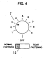
- a type of a rotary switch shown in FIG. 4 or a type with a level meter LED1 of LED (light emitting diode) arrays and arrow keys used for increase or decrease the level of the indication of the level meter LED1 can be used.
- a type of a sliding switch shown in FIG. 4 or a type with a light emitting display LED2 such as an LED and a push switch can be used.
- the rotary impact tool is essentially used in a normal fastening mode without tight fastening.
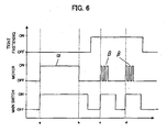
- a normal fastening mode when the main switch 2 is switched on, the motor 3 starts to rotate, and the impact blows of the hammer 40 occurs, as shown in FIG. 6 .
- the controller 5 switches off the switching device 4 so as to stop the driving of the motor 3, even in the switching on of the main switch 2.
- a term designated by a symbol ⁇ shows such a normal fastening operation.
- a predetermined number of impact blows of the hammer are performed.
- the impact blows of the hammer are performed in a predetermined term, until a number of rotations of the shaft of the motor 3 reaches to a predetermined reference number, or until the rotation angle of the output shaft 31 reaches to a predetermined angle.
- the controller 5 stops driving of the motor 3 although the main switch 2 is switched on by the user. After that, when the main switch 2 is once switched off and switched on again, the controller 5 repeats the tight fastening operation until the tight fastening mode is off.
- FIG. 7 shows a block configuration of another rotary impact tool in accordance with a second embodiment of the present invention.
- the rotary impact tool in the second embodiment further comprises a tight fastening angle setting switch 8.
- a tight fastening angle setting switch 8 In the tight fastening mode, it is possible that the impact blows of the hammer 40 are performed by a tight fastening angle set in the tight fastening angle setting switch 8.
- the level of the phase of the torque set in the torque setting switch 7 is increased by one, when the tight fastening operations are repeated more than a predetermined times continuously.
- the fastening torque in the next normal fastening mode or the quantity of the impact energy in the next tight fastening operation can be increased, automatically.
- the level of the phase set in the torque setting switch 7 is automatically increased by one.
- the rotary impact tool in the first and second embodiments comprises the fastening term sensor 9.
- a term T1 between a time when the main switch 2 is switched off and a time when the main switch 2 is switched on again by the user is shorter than a predetermined term T2
- the controller 5 can perform the tight fastening operation designated by the symbol ⁇ , although the tight fastening mode setting switch 12 is switched off.
Description
- The present invention relates to a rotary impact tool such as an impact wrench or an impact driver used for fastening or loosening of fastening member such as a screw, a bolt or a nut. Such a tool is known from
EP 1207016 A2 . - A rotary impact tool which can stop the driving of the motor automatically when a fastening torque reaches to a predetermined value is conventionally provided. In the actual fastening work, there, however, are many cases that the fastening torque of the fastening member is insufficient for preventing the over fastening. For preventing occurrence of the insufficient fastening torque, Japanese Laid-Open Patent Publication No.
2001-129767 - In such a conventional rotary impact tool, when the user holds a main switch on after stopping to motor when a controller judges that the fastening torque reaches to a predetermined torque, the controller restarts the driving of the motor so as to apply a predetermined number of impact blows of a hammer, so that the tight fastening can be performed.
- In such a conventional rotary impact tool with the tight fastening mode, the tight fastening mode cannot be transitive when the switching on state of the main switch after stopping the driving of the motor is maintained. Thus, if the user judges that the fastening of the fastening member is completed due to stop of the driving of the motor, the tight fastening mode cannot be transitive.
- In another known rotary impact tool, as described in
US Patent No. 3,780,603 , a degree of "over tightening" is achieved by presetting a counter in order that the tool delivers a predetermined number of impacts after having reached its predetermined torque. Hence, the over tightening is also not transitive. - Furthermore, in the viewpoint of actual fastening operation, when there are a lot of members to be fastened, it is desirable that all the fastening members are fastened in normal fastening mode, and the tight fastening is continuously performed to the fastening members. The conventional rotary impact tool with the tight fastening mode, however, cannot be performed the tight fastening operation independently from the normal fastening operation, continuously.
- A purpose of the present invention is to provide a rotary impact tool, which can perform the tight fastening operation independently from the normal fastening operation, continuously.
- A rotary impact tool in accordance with an aspect of the present invention is recited in
Claim 1. Preferably the rotary impact tool comprises: a rotary driving mechanism including a motor for rotating a driving shaft; a hammer engaged with the driving shaft; an output shaft to which a driving force is applied by impact blow of the hammer; a main switch operated by a user for controlling fastening operation; a torque setting switch used by a user for setting a fastening torque; a torque calculator for calculating a fastening torque; and a controller for controlling on and off of the motor based on switching on and off of the main switch, an output of the torque calculator and the fastening torque set in the torque setting switch, and having a normal fastening mode and a tight fastening mode. - The rotary impact tool further comprises a tight fastening mode setting switch used for setting the tight fastening mode. When the tight fastening mode setting switch is switched on, the controller continuously drives the rotary driving mechanism so as to perform tight fastening operation continuously.
- By such a configuration, when a user wishes to fasten a plurality of fastening members such as screws, bolts or nuts in tight fastening mode, the rotary impact tool can perform the tight fastening operations continuously when the tight fastening mode setting switch is switched on. Therefore, it is possible that all the fastening members are fastened in normal fastening mode, and the tight fastening is continuously performed to the fastening members.
-
-
FIG. 1 is a block diagram showing a configuration of a rotary impact tool in accordance with a first embodiment of the present invention; -
FIG. 2 is a schematic sectional side view showing the configuration of the rotary impact tool in the first embodiment; -
FIG. 3 is a sectional side view showing an example of a configuration of a driving mechanism of the rotary impact tool in the first embodiment; -
FIG. 4 is a front view showing an example of a torque setting switch and a tight fastening mode setting switch of the rotary impact tool in the first embodiment; -
FIG. 5 is a front view showing another example of a torque setting unit and a tight fastening mode setting switch of the rotary impact tool in the first embodiment; -
FIG. 6 is a time chart showing an example of an operation of the rotary impact tool in the first embodiment; -
FIG. 7 is a block diagram showing a configuration of a rotary impact tool in accordance with a second embodiment of the present invention; and -
FIG. 8 is a time chart showing an example of an operation of the rotary impact tool in the second embodiment. - A rotary impact tool in accordance with a first embodiment of the present invention is described. A block configuration of the rotary impact tool is shown in
FIG. 1 . The rotary impact tool comprises amain switch 2 used for controlling the fastening operation, amotor 3, aswitching device 4 used for on and off of driving themotor 3, a controller (control circuit) 5, animpact sensor 6 which further serves as a rotation angle sensor, atorque setting switch 7 used for setting a fastening torque, a fastening term sensor (sensing circuit) 9, abattery 10 as a power source, a torque calculator (calculating circuit) 11 and a tight fasteningmode setting switch 12. Thebattery 10, themain switch 2, themotor 3 and theswitching device 4 are connected in series, and the series circuit is connected in parallel with thecontroller 5. -
FIG. 2 shows schematic configuration of the rotary impact tool, andFIG. 3 shown specific example of adriving mechanism 30 for performing fastening operation of a fastening member such as a screw, a bolt or a nut by impact blow. As shown inFIG. 3 , a reducer is configured by asun gear 34, a pair ofplanet gears 32, and aninternal gear 33.Rotation shafts 35 of theplanet gears 32 are borne on a drivingshaft 36. Rotation force of themotor 3 is transmitted to thedriving shaft 36 via the reducer. Ahammer 40 is engaged with an outer face of the drivingshaft 36 viaball bearings 38 and acam 39. A spring 37 is further provided between thedriving shaft 36 and thehammer 40 for pressing thehammer 40 forward. Thehammer 40 further has at least one engaging portion engaging with an anvil provided on anoutput shaft 31. - When no load is applied to the
output shaft 31, thehammer 40 and theoutput shaft 31 are integrally rotated by the driving force of themotor 3. When a load equal to or larger than a predetermined value is applied to theoutput shaft 31, the hammer moves backward against the pressing force of the spring 37. When the engagement of thehammer 40 with the anvil of theoutput shaft 31 is released, thehammer 40 moves forward with rotation and applies impact blow in the rotation direction to the anvil of theoutput shaft 31, so that theoutput shaft 31 can be rotated. - In this embodiment, the
impact sensor 6 senses not only the occurrence of the impact blow of thehammer 40 with the anvil of theoutput shaft 31, but also a rotation angle of the anvil or theoutput shaft 31 in each impact blow of thehammer 40. As for theimpact sensor 6, it is possible to include a rotary encoder provided on themotor 3 for sensing the rotation of the shaft of themotor 3. As the rotary encoder, a frequency generator, a magnetic rotary encode or an optical rotary encoder can be used. The frequency generator has a magnetized disc fixed on the shaft of the motor, and senses the rotation of the disc with a coil. The magnetic rotary encoder has a magnetized disc fixed on the shaft of the motor, and senses the rotation of the disc with a hall IC. The optical rotary encoder has a disc with slits fixed on the shaft of the motor, and senses the rotation of the disc with a photo-coupler. Output signal from the rotation encoder is processed the waveform shaping of pulse width signal corresponding to the rotation speed of themotor 3 through a waveform shaping circuit (not shown), and transmitted to theimpact sensor 6. - Since the rotation speed of the
motor 3 falls slightly due to a load change at the time of occurrence of the impact blow, theimpact sensor 6 senses the occurrence of the impact blow of thehammer 40 utilizing a phenomenon that the pulse width of output of the rotation encoder becomes slightly longer. - The
impact sensor 6, however, is not limited to this configuration. It is possible to sense the occurrence of the impact blow with using blow sound gathered with a microphone or with using an acceleration sensor. - In case that the
torque calculator 11 calculates the fastening torque T1 based on a number N of impact blows of thehammer 40, it is possible to estimate the fastening torque T1 as the following formula.
- In case that the
torque calculator 11 calculates the fastening torque T1 based a rotation angle θ of theoutput shaft 31 in each impact blow of thehammer 40, it is possible to calculate the fastening torque T2 as the following formulae.

- Hereupon, rotation quantity (or angle) of the shaft of the
motor 3 at each impact blow is designated by a symbol of Δ n, a reduction ratio from the shaft of themotor 3 to theoutput shaft 31 is designated by a symbol η, and a rotation speed of themotor 3 is designated by ω. - The
fastening term sensor 9 is connected in parallel with themain switch 2 so as to measure on time and off time of themain switch 2. - As for the
torque setting switch 7, a type of a rotary switch shown inFIG. 4 or a type with a level meter LED1 of LED (light emitting diode) arrays and arrow keys used for increase or decrease the level of the indication of the level meter LED1 can be used. - As for the tight fastening
mode setting switch 12, a type of a sliding switch shown inFIG. 4 , or a type with a light emitting display LED2 such as an LED and a push switch can be used. - The rotary impact tool is essentially used in a normal fastening mode without tight fastening. In such a normal fastening mode, when the
main switch 2 is switched on, themotor 3 starts to rotate, and the impact blows of thehammer 40 occurs, as shown inFIG. 6 . When a fastening torque calculated in thetorque calculator 11 reaches to a value of the torque set in thetorque setting switch 7, thecontroller 5 switches off theswitching device 4 so as to stop the driving of themotor 3, even in the switching on of themain switch 2. InFIG. 6 , a term designated by a symbol α shows such a normal fastening operation. - When a user judges that it is further necessary for fastening the fastening member in tight fastening mode after switching off the
main switch 2 due to stopping themotor 3, it is possible to make transition to the tight fastening mode by operating the tight fasteningmode setting switch 12. After the transition to the tight fastening mode, when the user switched on themain switch 2 again, thecontroller 5 performs the tight fastening operation which is designated by a symbol β inFIG. 6 , which is different from the normal fastening operation designated by the symbol α. - As for the tight fastening operation, for example, a predetermined number of impact blows of the hammer are performed. Alternatively, the impact blows of the hammer are performed in a predetermined term, until a number of rotations of the shaft of the
motor 3 reaches to a predetermined reference number, or until the rotation angle of theoutput shaft 31 reaches to a predetermined angle. - In case for performing the predetermined number of impact blows of the
hammer 40, when the predetermined number of impact blows of thehammer 40 has been completed, thecontroller 5 stops driving of themotor 3 although themain switch 2 is switched on by the user. After that, when themain switch 2 is once switched off and switched on again, thecontroller 5 repeats the tight fastening operation until the tight fastening mode is off. - As for the above-mentioned predetermined number of the impact blows of the
hammer 40, it is preferable to be set a value corresponding to the value of the fastening torque set in thetorque setting switch 7. An example of relations between the values of phases of thetorque setting switch 7 and the numbers of the impact blows of thehammer 40 is shown in the following table 1.Table 1 VALUE OF PHASES OF TORQUE NUMBER OF IMPACT BLOWS 1 2 2 4 3 6 4 8 ... ··· 9 30 -
FIG. 7 shows a block configuration of another rotary impact tool in accordance with a second embodiment of the present invention. The rotary impact tool in the second embodiment further comprises a tight fasteningangle setting switch 8. In the tight fastening mode, it is possible that the impact blows of thehammer 40 are performed by a tight fastening angle set in the tight fasteningangle setting switch 8. Alternatively, it is possible to provide a switch for setting a number or a term of impact blows of the hammer instead of the tight fasteningangle setting switch 8. - It is further possible that the level of the phase of the torque set in the
torque setting switch 7 is increased by one, when the tight fastening operations are repeated more than a predetermined times continuously. By such a configuration, the fastening torque in the next normal fastening mode or the quantity of the impact energy in the next tight fastening operation can be increased, automatically. Specifically, when the tight fastening operation in which the estimated fastening torque corresponds to the level of thephase 2 is performed, the level of the phase set in thetorque setting switch 7 is automatically increased by one.Table 2 VALUE OF PHASES OF TORQUE VALUE OF ESTIMATED TORQUE 1 5 2 7 3 10 4 15 ··· ··· 9 45 - By the way, if the tight fastening operation cannot be performed without the switching operation in the tight
mode setting switch 12, it is necessary for switching the tightmode setting switch 12, even when the user wishes to perform the tight fastening operation in succession to the normal fastening operation. It causes the decrease of the operationality of the rotary impact tool. - Then, the rotary impact tool in the first and second embodiments comprises the
fastening term sensor 9. As shown inFIG. 8 , when a term T1 between a time when themain switch 2 is switched off and a time when themain switch 2 is switched on again by the user is shorter than a predetermined term T2, after the driving of themotor 3 is off due to completion of the normal fastening operation designated by the symbol α, it is possible that thecontroller 5 can perform the tight fastening operation designated by the symbol β, although the tight fasteningmode setting switch 12 is switched off.
Claims (3)
- A rotary impact tool comprising:a rotary driving mechanism (30) including a motor (3) for rotating a driving shaft (36);a hammer (40) engaged with the driving shaft (36);an output shaft (31) to which a driving force is applied by impact blow of the hammer (40);a main switch (2) operated by a user for controlling fastening operation;a torque setting switch (7) used by a user for setting a fastening torque;a torque calculator (11) for calculating a fastening torque;a controller (5) for controlling on and off of the motor (3) based on switching on and off of the main switch (2), an output of the torque calculator (11) and the fastening torque set in the torque setting switch (7), and having a normal fastening mode and a tight fastening mode; andan impact sensor (6) for sensing occurance of the impact blow of the hammer (49) and rotation angle of the output shaft (31) to which rotation force due to impact blow of the hammer (40) is applied or a rotation angle of a shaft of the motor (3);a tight fastening mode setting switch (12) used for setting the tight fastening mode in which a fastening member is fastened further to stop fastening of the fastening member in normal fastening torque,characterized by:a fastening term sensor (9) for measuring on time and off time of the main switch (2) is connected in parallel with the main switch (2);the torque calculator (11) calculating the fastening torque based on an output of the impact sensor (6);when the tight fastening mode setting switch (12) is switched off, the controller (5) drives the rotary driving mechanism (30) in the normal fastening mode to stop the driving of the motor (3) when a fastening torque calculated in the torque calculator (11) reaches to a value of torque set in the torque setting switch (7) even in switching on of the main switch (2);when the tight fastening mode setting switch (12) is switched on, and when the main switch (2) is switched on, the controller (5) performs tight fastening operation so that a predetermined number of the impact blows of the hammer (40) are performed in a predetermined term, until a number of rotations of the shaft of the motor (3) reaches a predetermined reference number or until the rotation angle of the output shaft (31) reaches a predetermined angle andwhen a term, T1, between a time when the main switch (2) is switched off and a time when the main switch (2) is switched on again by the user measured by the fastening term sensor (9) is shorter than a predetermined time, T2, after the driving of the motor (3) is off due to completion of the normal fastening operation, the controller (5) performs the tight fastening operation, although the tight fastening mode setting switch (12) is switched off.
- The rotary impact tool in accordance with claim 1 further comprising:a tight fastening angle setting switch (8) used for setting or varying the predetermined reference value set in the tight fastening mode.
- The rotary impact tool in accordance with one of claims 1 or 2, wherein
the controller (5) increases a level of phase of the fastening torque set in the torque setting switch (7) by one, when a number of tight fastening operations reaches to a predetermined times.
Applications Claiming Priority (2)
| Application Number | Priority Date | Filing Date | Title |
|---|---|---|---|
| JP2004142844 | 2004-05-12 | ||
| JP2004142844A JP4400303B2 (en) | 2004-05-12 | 2004-05-12 | Impact rotary tool |
Publications (3)
| Publication Number | Publication Date |
|---|---|
| EP1595649A2 EP1595649A2 (en) | 2005-11-16 |
| EP1595649A3 EP1595649A3 (en) | 2007-05-02 |
| EP1595649B1 true EP1595649B1 (en) | 2013-03-13 |
Family
ID=34941270
Family Applications (1)
| Application Number | Title | Priority Date | Filing Date |
|---|---|---|---|
| EP05252923A Not-in-force EP1595649B1 (en) | 2004-05-12 | 2005-05-12 | Rotary impact tool |
Country Status (4)
| Country | Link |
|---|---|
| US (1) | US20050263305A1 (en) |
| EP (1) | EP1595649B1 (en) |
| JP (1) | JP4400303B2 (en) |
| CN (1) | CN100450725C (en) |
Families Citing this family (59)
| Publication number | Priority date | Publication date | Assignee | Title |
|---|---|---|---|---|
| JP4400519B2 (en) * | 2005-06-30 | 2010-01-20 | パナソニック電工株式会社 | Impact rotary tool |
| JP4998079B2 (en) * | 2007-05-11 | 2012-08-15 | 日立工機株式会社 | Electric tool |
| EP2722131B1 (en) | 2007-06-15 | 2016-07-20 | Black & Decker Inc. | Hybrid impact tool |
| JP5057145B2 (en) * | 2007-09-24 | 2012-10-24 | 日立工機株式会社 | Electric tool |
| EP2110921B1 (en) | 2008-04-14 | 2013-06-19 | Stanley Black & Decker, Inc. | Battery management system for a cordless tool |
| JP5112956B2 (en) * | 2008-05-30 | 2013-01-09 | 株式会社マキタ | Rechargeable power tool |
| GB2474221B (en) | 2008-08-06 | 2012-12-12 | Milwaukee Electric Tool Corp | Precision torque tool |
| US9193053B2 (en) * | 2008-09-25 | 2015-11-24 | Black & Decker Inc. | Hybrid impact tool |
| US8631880B2 (en) * | 2009-04-30 | 2014-01-21 | Black & Decker Inc. | Power tool with impact mechanism |
| JP5426978B2 (en) * | 2009-09-18 | 2014-02-26 | パナソニック株式会社 | Electric tool |
| US8460153B2 (en) * | 2009-12-23 | 2013-06-11 | Black & Decker Inc. | Hybrid impact tool with two-speed transmission |
| US8584770B2 (en) | 2010-03-23 | 2013-11-19 | Black & Decker Inc. | Spindle bearing arrangement for a power tool |
| DE102010029267A1 (en) * | 2010-05-25 | 2011-12-01 | Robert Bosch Gmbh | Power tool, in particular drill driver |
| DE102010030065A1 (en) | 2010-06-15 | 2011-12-15 | Hilti Aktiengesellschaft | driving- |
| DE102010030098A1 (en) | 2010-06-15 | 2011-12-15 | Hilti Aktiengesellschaft | driving- |
| DE102010030118A1 (en) | 2010-06-15 | 2011-12-15 | Hilti Aktiengesellschaft | driving- |
| DE102010030071A1 (en) * | 2010-06-15 | 2011-12-15 | Hilti Aktiengesellschaft | driving- |
| JP5486435B2 (en) * | 2010-08-17 | 2014-05-07 | パナソニック株式会社 | Impact rotary tool |
| WO2012061176A2 (en) | 2010-11-04 | 2012-05-10 | Milwaukee Electric Tool Corporation | Impact tool with adjustable clutch |
| DE102011005079A1 (en) * | 2011-03-04 | 2012-09-06 | Hilti Aktiengesellschaft | Setting method for an expansion anchor and impact wrench for setting a spreading anchor |
| JP5784473B2 (en) * | 2011-11-30 | 2015-09-24 | 株式会社マキタ | Rotating hammer tool |
| US9908182B2 (en) | 2012-01-30 | 2018-03-06 | Black & Decker Inc. | Remote programming of a power tool |
| CN103286727B (en) * | 2012-03-02 | 2015-06-10 | 南京德朔实业有限公司 | Impact wrench capable of adjusting twisting force |
| US9193055B2 (en) | 2012-04-13 | 2015-11-24 | Black & Decker Inc. | Electronic clutch for power tool |
| DE102012209446A1 (en) * | 2012-06-05 | 2013-12-05 | Robert Bosch Gmbh | Hand machine tool device |
| US20130327552A1 (en) * | 2012-06-08 | 2013-12-12 | Black & Decker Inc. | Power tool having multiple operating modes |
| US8919456B2 (en) | 2012-06-08 | 2014-12-30 | Black & Decker Inc. | Fastener setting algorithm for drill driver |
| JP2014069264A (en) * | 2012-09-28 | 2014-04-21 | Hitachi Koki Co Ltd | Electric power tool |
| WO2014084158A1 (en) * | 2012-11-29 | 2014-06-05 | 日立工機株式会社 | Impact tool |
| JP2014172163A (en) * | 2013-03-13 | 2014-09-22 | Panasonic Corp | Electric tool |
| JP5579902B2 (en) * | 2013-06-04 | 2014-08-27 | 株式会社マキタ | Electric tool |
| CN104516367B (en) * | 2013-09-26 | 2017-02-22 | 南京德朔实业有限公司 | Electric tool and threaded piece fastening degree control method |
| JP6245943B2 (en) * | 2013-10-31 | 2017-12-13 | Tone株式会社 | Fastening device |
| JP6304533B2 (en) | 2014-03-04 | 2018-04-04 | パナソニックIpマネジメント株式会社 | Impact rotary tool |
| US9893384B2 (en) | 2014-05-18 | 2018-02-13 | Black & Decker Inc. | Transport system for convertible battery pack |
| EP3654488A1 (en) | 2014-05-18 | 2020-05-20 | Black & Decker Inc. | Ac/dc power tools with brushless motors |
| EP2985117A1 (en) * | 2014-08-12 | 2016-02-17 | HILTI Aktiengesellschaft | Optimised setting procedure for an expansible anchor |
| EP2985118A1 (en) * | 2014-08-12 | 2016-02-17 | HILTI Aktiengesellschaft | Optimised setting procedure for an expansible anchor |
| CN105751133A (en) * | 2014-12-18 | 2016-07-13 | 苏州博来喜电器有限公司 | Impact wrench |
| US10615670B2 (en) | 2015-06-05 | 2020-04-07 | Ingersoll-Rand Industrial U.S., Inc. | Power tool user interfaces |
| CN110712163B (en) | 2015-06-05 | 2021-09-24 | 英格索兰工业美国公司 | Lighting system for power tool |
| WO2016196979A1 (en) | 2015-06-05 | 2016-12-08 | Ingersoll-Rand Company | Impact tools with ring gear alignment features |
| WO2016196891A1 (en) | 2015-06-05 | 2016-12-08 | Ingersoll-Rand Company | Power tool user interfaces |
| WO2016196899A1 (en) | 2015-06-05 | 2016-12-08 | Ingersoll-Rand Company | Power tool housings |
| WO2016196984A1 (en) | 2015-06-05 | 2016-12-08 | Ingersoll-Rand Company | Power tools with user-selectable operational modes |
| JP6621013B2 (en) * | 2015-10-20 | 2019-12-18 | 勝行 戸津 | Method and system for determining whether screw tightening is good or bad |
| US10478950B2 (en) | 2015-11-26 | 2019-11-19 | Makita Corporation | Power tool |
| JP6400636B2 (en) * | 2015-11-26 | 2018-10-03 | 株式会社マキタ | Electric tool |
| CN106896763B (en) * | 2015-12-17 | 2020-09-08 | 米沃奇电动工具公司 | System and method for configuring a power tool having an impact mechanism |
| WO2018119256A1 (en) | 2016-12-23 | 2018-06-28 | Black & Decker Inc. | Cordless power tool system |
| JP6901346B2 (en) | 2017-08-09 | 2021-07-14 | 株式会社マキタ | Electric work machine |
| JP6916060B2 (en) * | 2017-08-09 | 2021-08-11 | 株式会社マキタ | Electric work machine |
| EP3501740A1 (en) * | 2017-12-20 | 2019-06-26 | HILTI Aktiengesellschaft | Setting method for threaded connection by means of impact wrench |
| JP7210291B2 (en) | 2019-01-10 | 2023-01-23 | 株式会社マキタ | electric driver drill |
| US11673240B2 (en) | 2019-08-06 | 2023-06-13 | Makita Corporation | Driver-drill |
| JP7320419B2 (en) | 2019-09-27 | 2023-08-03 | 株式会社マキタ | rotary impact tool |
| JP7386027B2 (en) * | 2019-09-27 | 2023-11-24 | 株式会社マキタ | rotary impact tool |
| EP4142982A1 (en) * | 2020-05-01 | 2023-03-08 | Milwaukee Electric Tool Corporation | Rotary impact tool |
| EP4263138A1 (en) | 2020-12-18 | 2023-10-25 | Black & Decker Inc. | Impact tools and control modes |
Family Cites Families (21)
| Publication number | Priority date | Publication date | Assignee | Title |
|---|---|---|---|---|
| US3780603A (en) * | 1972-05-11 | 1973-12-25 | Wolff Sales Eng Co | Impact control for impact wrenches |
| US4316512A (en) * | 1979-04-04 | 1982-02-23 | Sps Technologies, Inc. | Impact wrench |
| GB2232372A (en) * | 1989-05-25 | 1990-12-12 | Black & Decker Inc | Improvements in or relating to power tools |
| JP2943457B2 (en) * | 1991-09-30 | 1999-08-30 | トヨタ自動車株式会社 | Nutrunner |
| US5402688A (en) * | 1993-03-17 | 1995-04-04 | Sumitomo Metal Industries, Ltd. | Method and apparatus for determining the tightened condition of a pipe joint |
| JP3000185B2 (en) * | 1993-04-21 | 2000-01-17 | 株式会社山崎歯車製作所 | Bolt fastening method using impact wrench |
| GB9320181D0 (en) * | 1993-09-30 | 1993-11-17 | Black & Decker Inc | Improvements in and relating to power tools |
| JPH07100772A (en) * | 1993-10-01 | 1995-04-18 | Ricoh Co Ltd | Rotary type power tool |
| DE19503524A1 (en) * | 1995-02-03 | 1996-08-08 | Bosch Gmbh Robert | Impulse screwdriver and method for tightening a screw connection using the impulse screwdriver |
| JP3514034B2 (en) * | 1996-05-10 | 2004-03-31 | 日立工機株式会社 | Shear wrench |
| RU2238183C2 (en) * | 1999-03-16 | 2004-10-20 | Кукен Ко., Лтд. | Methods for reading rotation angle of manually driven nut driver, methods for detecting beatings and determining reliability of thread tightening, method for controlling manually driven unscrewing tool |
| JP3906606B2 (en) * | 1999-06-11 | 2007-04-18 | 松下電工株式会社 | Impact rotary tool |
| JP2001129767A (en) * | 1999-10-29 | 2001-05-15 | Matsushita Electric Works Ltd | Impact rotation tool |
| EP1136188B1 (en) * | 2000-03-16 | 2007-05-16 | Makita Corporation | Power impact tools with impact sound detecting means |
| JP3456949B2 (en) * | 2000-06-19 | 2003-10-14 | 株式会社エスティック | Method and apparatus for controlling screw tightening device |
| EP1867438A3 (en) * | 2000-11-17 | 2009-01-14 | Makita Corporation | Impact power tools |
| JP3886818B2 (en) * | 2002-02-07 | 2007-02-28 | 株式会社マキタ | Tightening tool |
| JP2004291138A (en) * | 2003-03-26 | 2004-10-21 | Matsushita Electric Works Ltd | Magnetic impact tool |
| JP4093145B2 (en) * | 2003-08-26 | 2008-06-04 | 松下電工株式会社 | Tightening tool |
| JP2005118910A (en) * | 2003-10-14 | 2005-05-12 | Matsushita Electric Works Ltd | Impact rotary tool |
| JP2005144564A (en) * | 2003-11-11 | 2005-06-09 | Matsushita Electric Works Ltd | Portable electric tool |
-
2004
- 2004-05-12 JP JP2004142844A patent/JP4400303B2/en not_active Expired - Fee Related
-
2005
- 2005-05-11 US US11/126,351 patent/US20050263305A1/en not_active Abandoned
- 2005-05-11 CN CNB2005100688046A patent/CN100450725C/en not_active Expired - Fee Related
- 2005-05-12 EP EP05252923A patent/EP1595649B1/en not_active Not-in-force
Also Published As
| Publication number | Publication date |
|---|---|
| EP1595649A2 (en) | 2005-11-16 |
| JP4400303B2 (en) | 2010-01-20 |
| CN1695899A (en) | 2005-11-16 |
| US20050263305A1 (en) | 2005-12-01 |
| CN100450725C (en) | 2009-01-14 |
| JP2005324264A (en) | 2005-11-24 |
| EP1595649A3 (en) | 2007-05-02 |
Similar Documents
| Publication | Publication Date | Title |
|---|---|---|
| EP1595649B1 (en) | Rotary impact tool | |
| EP1595651B1 (en) | Rotary impact tool | |
| EP1595650B1 (en) | Rotary impact tool | |
| US6945337B2 (en) | Power impact tool | |
| US6968908B2 (en) | Power tools | |
| JP4412377B2 (en) | Impact rotary tool | |
| EP1510299B1 (en) | Electric tool with a plurality of operation modes | |
| US7155986B2 (en) | Power fastening tool | |
| JP2011067910A (en) | Wheel nut tightening tool for automobile tire replacement | |
| JP3743188B2 (en) | Rotating hammer tool | |
| JP5716898B2 (en) | Electric tool | |
| EP1930123B1 (en) | Electric Screwdriver | |
| JP2024043261A (en) | Power tools and motor control methods for power tools | |
| JP4369257B2 (en) | Impact driver | |
| WO2023043664A1 (en) | Maximum power tool startup torque |
Legal Events
| Date | Code | Title | Description |
|---|---|---|---|
| PUAI | Public reference made under article 153(3) epc to a published international application that has entered the european phase |
Free format text: ORIGINAL CODE: 0009012 |
|
| AK | Designated contracting states |
Kind code of ref document: A2 Designated state(s): AT BE BG CH CY CZ DE DK EE ES FI FR GB GR HU IE IS IT LI LT LU MC NL PL PT RO SE SI SK TR |
|
| AX | Request for extension of the european patent |
Extension state: AL BA HR LV MK YU |
|
| PUAL | Search report despatched |
Free format text: ORIGINAL CODE: 0009013 |
|
| AK | Designated contracting states |
Kind code of ref document: A3 Designated state(s): AT BE BG CH CY CZ DE DK EE ES FI FR GB GR HU IE IS IT LI LT LU MC NL PL PT RO SE SI SK TR |
|
| AX | Request for extension of the european patent |
Extension state: AL BA HR LV MK YU |
|
| 17P | Request for examination filed |
Effective date: 20070914 |
|
| 17Q | First examination report despatched |
Effective date: 20071024 |
|
| AKX | Designation fees paid |
Designated state(s): AT BE BG CH CY CZ DE DK EE ES FI FR GB GR HU IE IS IT LI LT LU MC NL PL PT RO SE SI SK TR |
|
| RAP1 | Party data changed (applicant data changed or rights of an application transferred) |
Owner name: PANASONIC ELECTRIC WORKS CO., LTD. |
|
| RAP1 | Party data changed (applicant data changed or rights of an application transferred) |
Owner name: PANASONIC CORPORATION |
|
| GRAP | Despatch of communication of intention to grant a patent |
Free format text: ORIGINAL CODE: EPIDOSNIGR1 |
|
| GRAS | Grant fee paid |
Free format text: ORIGINAL CODE: EPIDOSNIGR3 |
|
| GRAA | (expected) grant |
Free format text: ORIGINAL CODE: 0009210 |
|
| STAA | Information on the status of an ep patent application or granted ep patent |
Free format text: STATUS: THE PATENT HAS BEEN GRANTED |
|
| AK | Designated contracting states |
Kind code of ref document: B1 Designated state(s): AT BE BG CH CY CZ DE DK EE ES FI FR GB GR HU IE IS IT LI LT LU MC NL PL PT RO SE SI SK TR |
|
| REG | Reference to a national code |
Ref country code: GB Ref legal event code: FG4D |
|
| REG | Reference to a national code |
Ref country code: CH Ref legal event code: EP Ref country code: AT Ref legal event code: REF Ref document number: 600493 Country of ref document: AT Kind code of ref document: T Effective date: 20130315 |
|
| REG | Reference to a national code |
Ref country code: IE Ref legal event code: FG4D |
|
| REG | Reference to a national code |
Ref country code: DE Ref legal event code: R096 Ref document number: 602005038545 Country of ref document: DE Effective date: 20130508 |
|
| PG25 | Lapsed in a contracting state [announced via postgrant information from national office to epo] |
Ref country code: BG Free format text: LAPSE BECAUSE OF FAILURE TO SUBMIT A TRANSLATION OF THE DESCRIPTION OR TO PAY THE FEE WITHIN THE PRESCRIBED TIME-LIMIT Effective date: 20130613 Ref country code: LT Free format text: LAPSE BECAUSE OF FAILURE TO SUBMIT A TRANSLATION OF THE DESCRIPTION OR TO PAY THE FEE WITHIN THE PRESCRIBED TIME-LIMIT Effective date: 20130313 Ref country code: ES Free format text: LAPSE BECAUSE OF FAILURE TO SUBMIT A TRANSLATION OF THE DESCRIPTION OR TO PAY THE FEE WITHIN THE PRESCRIBED TIME-LIMIT Effective date: 20130624 Ref country code: SE Free format text: LAPSE BECAUSE OF FAILURE TO SUBMIT A TRANSLATION OF THE DESCRIPTION OR TO PAY THE FEE WITHIN THE PRESCRIBED TIME-LIMIT Effective date: 20130313 |
|
| REG | Reference to a national code |
Ref country code: AT Ref legal event code: MK05 Ref document number: 600493 Country of ref document: AT Kind code of ref document: T Effective date: 20130313 |
|
| REG | Reference to a national code |
Ref country code: NL Ref legal event code: VDEP Effective date: 20130313 |
|
| REG | Reference to a national code |
Ref country code: LT Ref legal event code: MG4D |
|
| PG25 | Lapsed in a contracting state [announced via postgrant information from national office to epo] |
Ref country code: GR Free format text: LAPSE BECAUSE OF FAILURE TO SUBMIT A TRANSLATION OF THE DESCRIPTION OR TO PAY THE FEE WITHIN THE PRESCRIBED TIME-LIMIT Effective date: 20130614 Ref country code: FI Free format text: LAPSE BECAUSE OF FAILURE TO SUBMIT A TRANSLATION OF THE DESCRIPTION OR TO PAY THE FEE WITHIN THE PRESCRIBED TIME-LIMIT Effective date: 20130313 Ref country code: SI Free format text: LAPSE BECAUSE OF FAILURE TO SUBMIT A TRANSLATION OF THE DESCRIPTION OR TO PAY THE FEE WITHIN THE PRESCRIBED TIME-LIMIT Effective date: 20130313 |
|
| PG25 | Lapsed in a contracting state [announced via postgrant information from national office to epo] |
Ref country code: BE Free format text: LAPSE BECAUSE OF FAILURE TO SUBMIT A TRANSLATION OF THE DESCRIPTION OR TO PAY THE FEE WITHIN THE PRESCRIBED TIME-LIMIT Effective date: 20130313 |
|
| PG25 | Lapsed in a contracting state [announced via postgrant information from national office to epo] |
Ref country code: NL Free format text: LAPSE BECAUSE OF FAILURE TO SUBMIT A TRANSLATION OF THE DESCRIPTION OR TO PAY THE FEE WITHIN THE PRESCRIBED TIME-LIMIT Effective date: 20130313 Ref country code: CZ Free format text: LAPSE BECAUSE OF FAILURE TO SUBMIT A TRANSLATION OF THE DESCRIPTION OR TO PAY THE FEE WITHIN THE PRESCRIBED TIME-LIMIT Effective date: 20130313 Ref country code: EE Free format text: LAPSE BECAUSE OF FAILURE TO SUBMIT A TRANSLATION OF THE DESCRIPTION OR TO PAY THE FEE WITHIN THE PRESCRIBED TIME-LIMIT Effective date: 20130313 Ref country code: SK Free format text: LAPSE BECAUSE OF FAILURE TO SUBMIT A TRANSLATION OF THE DESCRIPTION OR TO PAY THE FEE WITHIN THE PRESCRIBED TIME-LIMIT Effective date: 20130313 Ref country code: PT Free format text: LAPSE BECAUSE OF FAILURE TO SUBMIT A TRANSLATION OF THE DESCRIPTION OR TO PAY THE FEE WITHIN THE PRESCRIBED TIME-LIMIT Effective date: 20130715 Ref country code: IS Free format text: LAPSE BECAUSE OF FAILURE TO SUBMIT A TRANSLATION OF THE DESCRIPTION OR TO PAY THE FEE WITHIN THE PRESCRIBED TIME-LIMIT Effective date: 20130713 Ref country code: AT Free format text: LAPSE BECAUSE OF FAILURE TO SUBMIT A TRANSLATION OF THE DESCRIPTION OR TO PAY THE FEE WITHIN THE PRESCRIBED TIME-LIMIT Effective date: 20130313 Ref country code: RO Free format text: LAPSE BECAUSE OF FAILURE TO SUBMIT A TRANSLATION OF THE DESCRIPTION OR TO PAY THE FEE WITHIN THE PRESCRIBED TIME-LIMIT Effective date: 20130313 |
|
| PG25 | Lapsed in a contracting state [announced via postgrant information from national office to epo] |
Ref country code: CY Free format text: LAPSE BECAUSE OF FAILURE TO SUBMIT A TRANSLATION OF THE DESCRIPTION OR TO PAY THE FEE WITHIN THE PRESCRIBED TIME-LIMIT Effective date: 20130313 Ref country code: PL Free format text: LAPSE BECAUSE OF FAILURE TO SUBMIT A TRANSLATION OF THE DESCRIPTION OR TO PAY THE FEE WITHIN THE PRESCRIBED TIME-LIMIT Effective date: 20130313 |
|
| PG25 | Lapsed in a contracting state [announced via postgrant information from national office to epo] |
Ref country code: MC Free format text: LAPSE BECAUSE OF FAILURE TO SUBMIT A TRANSLATION OF THE DESCRIPTION OR TO PAY THE FEE WITHIN THE PRESCRIBED TIME-LIMIT Effective date: 20130313 |
|
| REG | Reference to a national code |
Ref country code: CH Ref legal event code: PL |
|
| PLBE | No opposition filed within time limit |
Free format text: ORIGINAL CODE: 0009261 |
|
| STAA | Information on the status of an ep patent application or granted ep patent |
Free format text: STATUS: NO OPPOSITION FILED WITHIN TIME LIMIT |
|
| PG25 | Lapsed in a contracting state [announced via postgrant information from national office to epo] |
Ref country code: DK Free format text: LAPSE BECAUSE OF FAILURE TO SUBMIT A TRANSLATION OF THE DESCRIPTION OR TO PAY THE FEE WITHIN THE PRESCRIBED TIME-LIMIT Effective date: 20130313 Ref country code: CH Free format text: LAPSE BECAUSE OF NON-PAYMENT OF DUE FEES Effective date: 20130531 Ref country code: LI Free format text: LAPSE BECAUSE OF NON-PAYMENT OF DUE FEES Effective date: 20130531 |
|
| 26N | No opposition filed |
Effective date: 20131216 |
|
| REG | Reference to a national code |
Ref country code: IE Ref legal event code: MM4A |
|
| PG25 | Lapsed in a contracting state [announced via postgrant information from national office to epo] |
Ref country code: IT Free format text: LAPSE BECAUSE OF FAILURE TO SUBMIT A TRANSLATION OF THE DESCRIPTION OR TO PAY THE FEE WITHIN THE PRESCRIBED TIME-LIMIT Effective date: 20130313 |
|
| REG | Reference to a national code |
Ref country code: FR Ref legal event code: ST Effective date: 20140131 |
|
| REG | Reference to a national code |
Ref country code: DE Ref legal event code: R097 Ref document number: 602005038545 Country of ref document: DE Effective date: 20131216 |
|
| PG25 | Lapsed in a contracting state [announced via postgrant information from national office to epo] |
Ref country code: IE Free format text: LAPSE BECAUSE OF NON-PAYMENT OF DUE FEES Effective date: 20130512 |
|
| PG25 | Lapsed in a contracting state [announced via postgrant information from national office to epo] |
Ref country code: FR Free format text: LAPSE BECAUSE OF NON-PAYMENT OF DUE FEES Effective date: 20130531 |
|
| PG25 | Lapsed in a contracting state [announced via postgrant information from national office to epo] |
Ref country code: TR Free format text: LAPSE BECAUSE OF FAILURE TO SUBMIT A TRANSLATION OF THE DESCRIPTION OR TO PAY THE FEE WITHIN THE PRESCRIBED TIME-LIMIT Effective date: 20130313 |
|
| PG25 | Lapsed in a contracting state [announced via postgrant information from national office to epo] |
Ref country code: LU Free format text: LAPSE BECAUSE OF NON-PAYMENT OF DUE FEES Effective date: 20130512 Ref country code: HU Free format text: LAPSE BECAUSE OF FAILURE TO SUBMIT A TRANSLATION OF THE DESCRIPTION OR TO PAY THE FEE WITHIN THE PRESCRIBED TIME-LIMIT; INVALID AB INITIO Effective date: 20050512 |
|
| PGFP | Annual fee paid to national office [announced via postgrant information from national office to epo] |
Ref country code: DE Payment date: 20170523 Year of fee payment: 13 Ref country code: GB Payment date: 20170519 Year of fee payment: 13 |
|
| REG | Reference to a national code |
Ref country code: DE Ref legal event code: R119 Ref document number: 602005038545 Country of ref document: DE |
|
| GBPC | Gb: european patent ceased through non-payment of renewal fee |
Effective date: 20180512 |
|
| PG25 | Lapsed in a contracting state [announced via postgrant information from national office to epo] |
Ref country code: GB Free format text: LAPSE BECAUSE OF NON-PAYMENT OF DUE FEES Effective date: 20180512 Ref country code: DE Free format text: LAPSE BECAUSE OF NON-PAYMENT OF DUE FEES Effective date: 20181201 |