EP1595623A1 - Compound body manufacturing method, compound body manufacturing device, and compound body - Google Patents

Compound body manufacturing method, compound body manufacturing device, and compound body Download PDF

Info

Publication number
EP1595623A1
EP1595623A1 EP04700171A EP04700171A EP1595623A1 EP 1595623 A1 EP1595623 A1 EP 1595623A1 EP 04700171 A EP04700171 A EP 04700171A EP 04700171 A EP04700171 A EP 04700171A EP 1595623 A1 EP1595623 A1 EP 1595623A1
Authority
EP
European Patent Office
Prior art keywords
outer part
manufacturing
melt
compound
compound according
Prior art date
Legal status (The legal status is an assumption and is not a legal conclusion. Google has not performed a legal analysis and makes no representation as to the accuracy of the status listed.)
Withdrawn
Application number
EP04700171A
Other languages
German (de)
French (fr)
Other versions
EP1595623A4 (en
Inventor
Makoto Katsumata
Hitoshi Ushijima
Hiroshi Suzuki
Kunio Okumura
Current Assignee (The listed assignees may be inaccurate. Google has not performed a legal analysis and makes no representation or warranty as to the accuracy of the list.)
Yazaki Corp
Original Assignee
Yazaki Corp
Priority date (The priority date is an assumption and is not a legal conclusion. Google has not performed a legal analysis and makes no representation as to the accuracy of the date listed.)
Filing date
Publication date
Application filed by Yazaki Corp filed Critical Yazaki Corp
Publication of EP1595623A1 publication Critical patent/EP1595623A1/en
Publication of EP1595623A4 publication Critical patent/EP1595623A4/en
Withdrawn legal-status Critical Current

Links

Images

Classifications

    • BPERFORMING OPERATIONS; TRANSPORTING
    • B22CASTING; POWDER METALLURGY
    • B22DCASTING OF METALS; CASTING OF OTHER SUBSTANCES BY THE SAME PROCESSES OR DEVICES
    • B22D19/00Casting in, on, or around objects which form part of the product
    • B22D19/02Casting in, on, or around objects which form part of the product for making reinforced articles
    • BPERFORMING OPERATIONS; TRANSPORTING
    • B22CASTING; POWDER METALLURGY
    • B22DCASTING OF METALS; CASTING OF OTHER SUBSTANCES BY THE SAME PROCESSES OR DEVICES
    • B22D19/00Casting in, on, or around objects which form part of the product
    • B22D19/14Casting in, on, or around objects which form part of the product the objects being filamentary or particulate in form
    • BPERFORMING OPERATIONS; TRANSPORTING
    • B22CASTING; POWDER METALLURGY
    • B22DCASTING OF METALS; CASTING OF OTHER SUBSTANCES BY THE SAME PROCESSES OR DEVICES
    • B22D18/00Pressure casting; Vacuum casting
    • B22D18/02Pressure casting making use of mechanical pressure devices, e.g. cast-forging
    • CCHEMISTRY; METALLURGY
    • C22METALLURGY; FERROUS OR NON-FERROUS ALLOYS; TREATMENT OF ALLOYS OR NON-FERROUS METALS
    • C22CALLOYS
    • C22C1/00Making non-ferrous alloys
    • C22C1/10Alloys containing non-metals
    • CCHEMISTRY; METALLURGY
    • C22METALLURGY; FERROUS OR NON-FERROUS ALLOYS; TREATMENT OF ALLOYS OR NON-FERROUS METALS
    • C22CALLOYS
    • C22C21/00Alloys based on aluminium
    • CCHEMISTRY; METALLURGY
    • C22METALLURGY; FERROUS OR NON-FERROUS ALLOYS; TREATMENT OF ALLOYS OR NON-FERROUS METALS
    • C22CALLOYS
    • C22C23/00Alloys based on magnesium
    • YGENERAL TAGGING OF NEW TECHNOLOGICAL DEVELOPMENTS; GENERAL TAGGING OF CROSS-SECTIONAL TECHNOLOGIES SPANNING OVER SEVERAL SECTIONS OF THE IPC; TECHNICAL SUBJECTS COVERED BY FORMER USPC CROSS-REFERENCE ART COLLECTIONS [XRACs] AND DIGESTS
    • Y10TECHNICAL SUBJECTS COVERED BY FORMER USPC
    • Y10TTECHNICAL SUBJECTS COVERED BY FORMER US CLASSIFICATION
    • Y10T29/00Metal working
    • Y10T29/49Method of mechanical manufacture
    • Y10T29/49616Structural member making

Definitions

  • the present invention relates to a method and apparatus for manufacturing a compound and to a compound, and more particularly to a compound suited for use in a structure requiring light weight and high strength and to a method of manufacturing same.
  • Patent Document 1 JP-A-11-29831 (pages 2 to 3, Fig. 1)
  • the present invention has been made in view of the above circumstances, wherein it is an object to provide a compound light in weight and high in strength and a method and apparatus for same.
  • the invention proposes the following problem-solving means in order to solve the above problem.
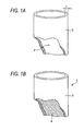
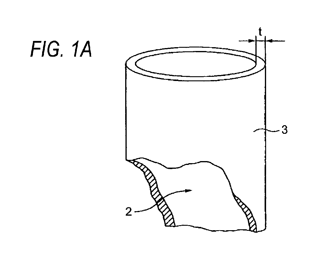
  • FIGs. 1 and 2B are views showing one embodiment of a compound according to the invention, wherein Fig. 1A is a perspective view of an outer part while Fig. 1B is a perspective view of the compound structure.
  • reference numeral 1 shows a compound to be suitably used in a structure requiring light weight and high strength.
  • the compound 1 is structured with a metal outer part 3 having a hollow space 2 and a content material 4 formed in the hollow space 2.
  • the outer part 3 has a desired exterior form, which herein has a desired wall thickness t and formed in a pipe form having smooth inner and outer surfaces.
  • the content material 4 is to reduce the weight and improve the strength of the compound 1, which herein is formed in a state filling the hollow space 2.
  • the compound 1 like this, although explained later in detail with using another outer part than the outer part 3, is manufactured by a manufacturing apparatus structured, as described later, including an outer-part forming process and an inner-body forming process.
  • the body in various kinds, according to the invention including the compound 1, is structured light in weight and high in strength, owing to the combination of an outer part and a content material formed in the hollow space of the outer part.
  • those are applicable as substitutes for structures, such as pipes, panels, cases and covers, presently used in broad technical fields.
  • substitution is possible for the structures in broad technical fields including uprights such as of antenna poles, frames for bicycles and wheelchairs, automobile-body reinforcing members such as impact beams and tower bars, soundproof members, shield panel members, at-worksite foothold members, office-automating members, shield box members such as ECU cases and junction block covers, engine head cover members, aircrafts, shipping, railroad cars, space fields, harbor facilities, signal posts, ski poles, and so on.
  • the outer part of the invention including the outer part 3, is provided as a part forming an exterior shape as a product.
  • the outer part is formed with various forms such as a pipe formed of a metal of stainless steel, aluminum, copper, iron, titanium, ceramics (pipe, plate molded member) or punched metal (mesh form), a pipe worked by forming, a plate formed of the foregoing metal, a press-worked plate by pressing, or joined ones of those by welding or so.
  • the outer part having a hollow space, is formed to serve as a charge vessel for forming a content material.
  • the hollow space may be formed by use of a separate member that can be removed after forming a content material (the separate member be explained later as a pin-like piece 110B-a in Figs. 18, 19A and 19B).
  • the content material of the invention including the content material 4 is formed by using a moldable metal matrix melt and a filler contained in the melt.
  • the metal matrix herein uses an aluminum die-cast alloy (e.g. ADC12 or the like, JIS Standard) (metal matrix may otherwise include Mg (magnesium)).
  • the filler, intended for weight reduction and strength improvement, herein uses a light-weight filler, an inorganic filler or a fiber in various kinds.
  • the light-weight filler includes, as an example, a hollow particle (ceramic hollow particle) of silica, alumina, mullite or the like (incidentally, the hollow particle is not limitative but a solid particle may be employed).
  • the fiber in various kinds includes a ceramic fiber, a ceramic whisker, a carbon fiber and a felt, as examples.
  • the filler may be a mixture of two or more of the above examples.
  • the compound may be manufactured by use of an outer part having an exterior shape as shown in Figs. 2A and 2B for example, besides structured with using the outer part 3 as in the compound 1 (a compound can be manufactured having an exterior shape suited to a product application).
  • Fig. 2A and 2B are views showing another embodiment of a compound of the invention.
  • Fig. 2A is a perspective view showing a compound that the outer part is formed in a cylindrical form having a rectangular section while
  • Fig. 2B is a perspective view showing a compound that the outer part is formed by joining press-worked plates together.
  • a compound 11 having light weight and high strength is structured with a metal outer part 13 having a hollow space 12 and a content material 14 formed in the hollow space 12.
  • the outer part 13 is a cylindrical member opened at both ends and having a rectangular section, whose interior is formed as a hollow space 12.
  • the content material 14 is formed of the same substance as the foregoing content material 4.
  • the compound 11 is made lighter in weight than the solid structure having the same exterior shape formed of the metal material of the outer part 13. Furthermore, it has a higher strength than the outer part 13 single or the content material 14 single.
  • a compound 21 having light weight and high strength is structured with a metal outer part 23 having a hollow space 22 (see Fig. 16) and a content material 24 formed in the hollow space 22.
  • the outer part 23 is structured with a plate 23b having an opening 23a for charging or pouring the filler and metal melt into the hollow space 22, and a press-worked plate 23d nearly in a boat form having a recess 23c. Meanwhile, the outer part 23 is formed by welding or merely contacting the plate 23b and the press-worked plate 23d together, as shown in the figure.
  • the content material 24 is formed of the same as the foregoing content material 4.
  • the compound 21 like this is made lighter in weight than the solid structure having the same exterior shape and of the metal material of the outer part 23. Furthermore, it is higher in strength than the outer part 23 single or the content material 14 single.
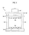
  • a compound manufacturing apparatus in the invention is structured with a lower plate 103 having a pair of rails 102, 102 extending horizontally (in a front-rear direction), a slide plate 104 in a two-member structure for slide based on the one pair of rails 102, 102, a plurality of column supports 105 vertically extending and having one ends fixed to the lower plate 103, an upper plate 106 fixed on the other ends of the column supports 105, a cylinder 107 fixed on the upper plate 106, an intermediate plate 108 inserted over the column supports 105 and for vertical slide with expansion/contraction of the cylinder 107, a pressurizing plate fixed on the intermediate plate 108 and opposed to the slide plate 104, for example.
  • the manufacturing apparatus 101 is structured having a lower mold die 110, melt die 111 and upper mold die 112, set up between the opposed slide plate 104 and pressurizing plate 109.
  • the lower mold die 110 is formed with an outer-part setter 113 for setting the outer part, and a fluid conduit port (air vent), not shown, communicating with the outer-part setter 113.
  • a filter (not shown) is attached, for example, at an opening edge of the not-shown fluid conduit port.
  • the melt die 111 is formed with a melt-charger 114 for charging the metal matrix melt.
  • the melt charger 114 is formed nearly in a funnel form in a manner continuing with the outer-part setter 113.
  • the opening formed in the outer part is formed in a position matched to the position of the melt charger 114.
  • a gasket is arranged in a region joining between the melt die 111 and the lower mold die 110.
  • An argon-gas pressurizer 115 (not limited to argon gas) on the upper mold die 112. Meanwhile, the upper mold die 112 is formed with a piping 116 leading the gas pressure of from the argon-gas pressurizer 115 to the interior of the melt charger 114.
  • the reference numeral 117 in the figure, represents a heater for use in heating.
  • the lower mold die 110 is assumed corresponding to a first mold die set forth in the claim.
  • the melt die 111 is assumed corresponding to a second mold die, similarly.
  • the melt die 111 and upper mold die 112 is assumed corresponding to content material forming means, similarly.
  • the upper mold die 112 is assumed corresponding to melt impregnating means similarly.
  • the heater 117 is assumed corresponding to a heater, similarly.
  • the compound manufacturing method based on the above structure is explained in one example thereof.
  • a process to charge a hollow particle 34a in the hollow space 32 of the outer part 33 (corresponding to a third step set forth in the claim).
  • a charge method e.g. charging by the action of vibration, interrupted feed under pressure (cutting by putting in a bag of a material (e.g. paper or resin) to vanish due to contact with a melt), etc.
  • this is not true for the charge timing of a hollow particle 34a. Namely, it may be done before setting up the outer part 33 to the outer setter 113.
  • a process step to set up an alumina filter 118 to an opening position of the outer part 33 is performed.
  • a process step to set up a melt die 111 on the lower mold die 110 is performed.
  • the opening of outer part 33 and the melt charger 114 of melt die 111 are aligned together sandwiching the alumina filter 118.
  • melt 34b charge a charge method is assumed suitably employed.
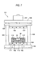
  • a process step to set up an upper mold die 112 on the melt die 111 is shown in Fig. 12.
  • the piping 116 in the upper mold die 112 is placed in communication with the melt charge 114 of the melt die 111.
  • the upper mold die 112 is urged by a descending pressurizing plate 109.
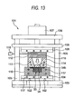
  • a process step to actuate the argon-gas pressurizer 115 on the upper mold die 112 and pressurize the melt charger 114 of melt die 111 with argon gas thereby pouring the metal-matrix melt 34b charged in the melt charger 114 into the hollow space 32 of outer part 33 (the description so far corresponding to a fourth step set fourth in the claim), as shown in Fig. 13.
  • the melt 34b poured in the hollow space 32 is impregnated in the hollow particle 34a, thereafter forming a content material 34.
  • a process step to remove the upper mold die 112 and melt die 111 to take a manufactured compound 31 out of the outer-part setter 113 of lower mold die 110 as shown in Fig. 14, and to remove the alumina filter 118 (corresponding to a fifth step set fourth in the claim).
  • the lower metal mold die 110 may be exchanged during the cooling, to pour a melt 34b through the melt die 111 into a hollow space of another outer part (not shown) set up on the another lower metal die (not shown) than that thereby forming a content material in the hollow space of the other outer part (not shown) (corresponding to a sixth step set forth in the claim). It is natural that productivity rate is to be improved by including this process step.
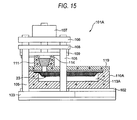
  • Fig. 15 is an explanatory view of a manufacturing apparatus corresponding to the compound in Fig. 2B.
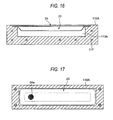
  • Fig. 16 is an explanatory view of a state the outer part is set up on the lower mold die
  • Fig. 17 is an explanatory view of a state that a hollow particle is charged in the outer part.
  • the apparatus 101 A for manufacturing the compound 21 (see Fig. 2B) is in a structure that, basically, the lower mold die 110 of the foregoing manufacturing apparatus 101 is replaced with a lower mold die 110A as in the following wherein such a hold die as shown at reference numeral 119 is newly provided.
  • the lower mold die 110A is formed with an outer-part setter 113A matched to the form of the outer part 23.
  • the outer part 23 is set up on the outer-part setter 113A, as shown in Fig. 16. Furthermore, as shown in Fig. 17, a hollow particle 24a is charged in the hollow space 22 and then an alumina filter 118 is set up on the outer part 23, on which the hold die 119 is further set up. Then, in case process steps are performed, in order, to set up the melt die 111 and the subsequent, manufacture is completed for a compound 21, having a light weight and high strength, structured with the outer part 23 and content material 24.
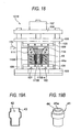
  • FIG. 18 is an explanatory view of a manufacturing apparatus for a compound using a pipe-formed outer part worked by forming.
  • Fig. 19A is a sectional view of an outer part worked by forming while Fig. 19B is a perspective view of a compound using the outer part of Fig. 19A.
  • the apparatus 101 B for manufacturing a compound 41 is basically structured that the lower mold die 110 of the foregoing manufacturing apparatus 101 is merely replaced with the following lower mold die 110B.
  • the lower mold die 110B is formed with an outer-part setter 113B matched to the form of outer part 43. Meanwhile, in the lower mold die 110B, there is provided a pin-formed piece 110B-a inserted in the hollow space 42 of outer part 42 and for forming a through-hole 41 a in a compound 41.
  • the outer part 43 is set up on the outer-part setter 113B, and a hollow particle 44a is charged in the hollow space 42. Then, an alumina filter is set up on the outer part 43. Then, in case process steps are performed, in order, to set up a melt die 111 and the subsequent, manufacture is completed for a compound 41, having a light weight and high strength, structured with the outer part 43 and content material 44.
  • FIG. 20 is an explanatory view of a manufacturing apparatus for a compound using an elongate-pipe-formed outer part.
  • Fig. 21 is a sectional view of an elongate-pipe-formed outer part.
  • an apparatus 101C for manufacturing a compound 41 is basically structured that the lower mold die 110 of the foregoing manufacturing apparatus 101 is merely replaced with the following lower mold die 110C.
  • the lower mold die 110C is structured with a first lower mold die 110C-a, a second lower mold die 110C-b, a die hold member 110C-c and a heater 110C-d.
  • the lower mold die 110C is formed as a mold die having a split structure such that the first lower mold die 110C-a and the second lower mold die 11C-b can clamp the outer part 53 at its one and the other ends formed in the above form.
  • the first lower mold die 110C-a and the second lower mold die 110C-b are respectively formed with outer-part setters 113C assuming a form capable of clamping the outer part 53.
  • the second lower mold die 110C-b is formed with a fluid conduit port (air vent) 110C-e.
  • the heater 110C-d uses induction heating so that the outer part 53 can be heated up directly.
  • the outer part 53 is set up at the respective outer-part setters 113C of the first lower mold die 110C-a and second lower mold die 110C-b, and a hollow particle is charged in a hollow space of the outer part 53. Then, a not-shown alumina filter is set up on the first lower mold die 110C-a. Then, in case process steps are performed, in order, to set up the melt die 111 and the subsequent, manufacture is completed for a compound 51, having a light weight and high strength, structured with the outer part 53 and content material 54.
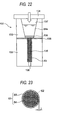
  • Fig. 22 is an explanatory view of a manufacturing apparatus for a compound using a pipe-formed outer part
  • Fig. 23 is a cross-sectional view of a compound using a pipe-formed outer part
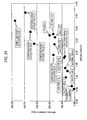
  • Fig. 24 is a graph showing a relationship between a strength and a specific gravity of a compound
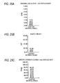
  • Figs. 25A - 25C are graphs showing a characteristic of a single content material
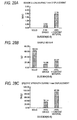
  • Figs. 26A - 29C are graphs showing a characteristic in using a pipe-formed outer part
  • Figs. 30A - 30C are graphs showing a characteristic in using a pipe-formed outer part (aluminum 1070 (t1, 0))
  • Figs. 31A - 31C are graphs showing a characteristic in using a pipe-formed outer part (SS (t1, 0))
  • Figs. 32 - 35 are graphs of a bending load.
  • the manufacturing apparatus 131 is structured by setting up a lower mold die (first die) 132, melt die (second die) and upper mold die 134 between a slide plate and a pressurizing plate that are opposed to each other, in a manner similar to the foregoing manufacturing apparatus (This is true as to manufacturing process).
  • the lower mold die 132 is formed with an outer-part setter 135 for setting up an outer part for a compound 61, and a fluid conduit port (air vent) 136 communicating with the outer-part setter 135.
  • a filter (not shown) is attached at an opening edge of the fluid conduit port 136.
  • the lower mold die 132 has a mold-die temperature set at 540 °C.
  • the melt die 133 is formed with a melt charger 137 for charging a metal-matrix melt 64a.
  • the melt charger 137 is formed in a funnel form in a manner continuing with the outer-part setter 135.
  • the melt die 133 has a die temperature set at 700 °C.
  • the melt 64a has a temperature also set at 700 °C.
  • a gasket 138 is arranged between the lower die 132 and the melt die 133. Meanwhile, a filter 139 is arranged between the outer-part setter 135 and the melt charger 137.
  • the arrow in the figure represents a pressure-applying direction of argon gas. In this embodiment, the application pressure to argon gas is set at 392 - 980 kPa.
  • the compound 61 manufactured by the manufacturing apparatus 131 is structured with a pipe-formed outer part 63 having a hollow 62, and a content material 64 formed in the hollow of the outer part 63.
  • the content material 64 is structured of a metal matrix and a light-weight filler.
  • the metal matrix uses an aluminum die-case alloy (ADC12 in JIS standard).
  • the light-weight filler is a hollow particle, blended with aluminum by 25 - 35%, iron oxide by 1 - 5% and titania by 0.5 - 1.5%, in a size of 10 - 350 ⁇ m.
  • Sample weights were measured for evaluations on the abive various samples. Meanwhile, measurements were made as to bending load during displacement by 1 mm of the sample. Furthermore, determined was specific tensile strength during displacement by 1 mm of the sample (bending load during 1-mm displacement/sample load).
  • Fig. 24 is a graph showing a relationship between a bending strength and specific weight of a compound, wherein specific weight is shown on the abscissa while bending strength is on the ordinate.
  • Figs. 25A and 34 the bending load during 1-mm displacement was 0.73 kN (fracture before 1 mm displacement) on a single content material 64. Meanwhile, in Fig. 25B, sample weight was 10.68g on the single content material 64. Meanwhile, in Fig. 25C, the specific strength during 1-mm displacement was 68.35 N/g on the single content material 64.
  • sample weight was 62.05g on an SUS304 solid material, 9.53g on a single outer part 63, and 18.57g on a compound 61 structured by an outer part 63 and a content material 64.
  • Fig. 27A and 33 sample weight was 62.05g on an SUS304 solid material, 9.53g on a single outer part 63, and 18.57g on a compound 61 structured by an outer part 63 and a content material 64.
  • sample weight was 62.05g on an SUS304 solid material, 14.00g on a single outer part 63, and 22.27g on a compound 61 structured by an outer part 63 and a content material 64.
  • Fig. 28B sample weight was 62.05g on an SUS304 solid material, 14.00g on a single outer part 63, and 22.27g on a compound 61 structured by an outer part 63 and a content material 64.
  • sample weight was 21.21 g on a solid material before heat treatment, 21.21 g on a solid material after heat treatment, 7.62g on a single outer part 63 before heat treatment, 7.62g on the single outer part 63 after heat treatment, and 14.45g on a compound 61 structured by an outer part 63 and a content material 64. Meanwhile, in Fig.
  • the specific strength during 1-mm displacement was 75.44 N/g on a solid material before heat treatment, 24.05 N/g on the solid material after heat treatment, 81.36 N/g on a single outer part 63 before heat treatment, 22.31 N/g on a single outer part 63 after heat treatment, and 46.37 on a compound 61 structured by a single outer part 63 after heat treatment and a content material 64.
  • sample weight was 60.08g on an SS solid material, 21.63g on a single outer part 63, and 28.47g on a compound 61 structured by an outer part 63 and a content material 64.
  • the present invention can provide a compound light in weight and high in strength and a method and apparatus for manufacturing such a compound.
  • the present invention is to exhibit an effect that can provide a method of manufacturing a compound light in weight and high in strength. Meanwhile, there is exhibited an effect that can provide an apparatus for manufacturing a compound light in weight and high in strength. Also, the invention is to exhibit an effect that can provide a compound light in weight and high in strength. The invention is to exhibit an effect that can improve the productivity rate. Meanwhile, the invention set forth in the other claim than the above is to provide an effect that can further improve the weight reduction and strength improvement for the compound.

Landscapes

  • Engineering & Computer Science (AREA)
  • Mechanical Engineering (AREA)
  • Chemical & Material Sciences (AREA)
  • Materials Engineering (AREA)
  • Metallurgy (AREA)
  • Organic Chemistry (AREA)
  • Manufacture Of Alloys Or Alloy Compounds (AREA)

Abstract
A compound (1) is manufactured which has a metal outer part (3) having a hollow space (2) and a content material (4) formed in the hollow space (2).
Namely, manufacture is made by including an outer part forming step to form an outer part and a content material forming step to form a content material (4) in the hollow space (2) by using a metal matrix melt to be die-molded and a filler contained in the melt. The outer part (3) has a desired exterior form.
Meanwhile, the content material (4) is formed in a state the hollow space (2) is filled in order to lighten the weight and improve the strength of the compound (1).
Figure 00000001

Description

Technical Field
The present invention relates to a method and apparatus for manufacturing a compound and to a compound, and more particularly to a compound suited for use in a structure requiring light weight and high strength and to a method of manufacturing same.
BACKGROUND ART
As the conventional compound for use in a structure requiring light weight and high strength, there are generally known those formed by arranging a pre-form (molded member) structured by using a ceramic hollow sphere, an inorganic fiber and a ceramic particle together in a mold die of a casting machine for die-cast or so and impregnating a metal matrix melt in the pre-form arranged in the mold die (see Patent Document 1, for example).
   Patent Document 1
      JP-A-11-29831 (pages 2 to 3, Fig. 1)
However, in recent years, there is a desire for those having a higher strength than the conventional compound while maintaining the state of lightweight.
DISCLOSURE OF THE INVENTION
The present invention has been made in view of the above circumstances, wherein it is an object to provide a compound light in weight and high in strength and a method and apparatus for same.
The invention proposes the following problem-solving means in order to solve the above problem.
  • (1) A method of manufacturing a compound comprising:
  • an outer part forming step of forming a metal outer part in a desired exterior form having a hollow space; and
  • a content material forming step of forming a content material in the hollow space by using a metal matrix melt to be die-molded and a filler contained in the melt.
  • (2) A method of manufacturing a compound according to (1), wherein
       the outer part is to be heated up by using induction heating.
  • (3) A method of manufacturing a compound according to (1), wherein
       the filler uses a hollow particle or a particle.
  • (4) A method of manufacturing a compound according to (1), wherein
       the filler uses a reinforcing fiber or a felt.
  • (5). A method of manufacturing a compound according to a mixture of two or more of a hollow particle, a particle, a reinforcing fiber and a felt.
  • (6) A method of manufacturing a compound, comprising:
  • a first step of forming a metal outer part in a desired form having a hollow space;
  • a second step of setting up the outer part on an outer part setter of a first mold die;
  • a third step of charging a filler in the hollow space by a predetermined charging manner;
  • a fourth step of charging a metal matrix melt to be die-molded into a second mold die and pouring the melt from the second mold die into the hollow space of the outer part set up on the first mold die so that the melt can be impregnated in the filler, thus forming a content material; and
  • a fifth step of taking the outer part out of the first mold die after cooling down the content material formed.
  • (7) A method of manufacturing a compound according to (6), further including a sixth step of pouring the melt from the second mold die into a hollow space of another outer part set up on another first mold die different from the first mold die before moving to the fifth step after executing the fourth step, and forming a content material in the hollow space in the other outer part.
  • (8) A method of manufacturing a compound according to (6), wherein
       the outer part is heated up by using induction heating.
  • (9) A method of manufacturing a compound according to (6), wherein
       the filler uses a hollow particle or a particle.
  • (10) A method of manufacturing a compound according to (6), wherein the filler uses a reinforcing fiber or a felt.
  • (11) A method of manufacturing a compound according to (6), wherein
       the filler uses a mixture of two or more of a hollow particle, a particle, a reinforcing fiber and a felt.
  • (12) An apparatus for manufacturing a compound, comprising:
  • a first mold die having an outer part setter for setting up a metal outer part in a desired exterior form having a hollow space; and
  • content material forming means for forming a content material in the hollow space by using a metal matrix melt to be die-molded and a filler contained in the melt.
  • (13) An apparatus for manufacturing a compound according to (12), wherein
       the heater for heating up the outer part is structured by using induction heating.
  • (14) An apparatus for manufacturing a compound according to (13), wherein
       a gasket is arranged between the first mold die and the second mold die, and a filter is arranged between the outer part set up on the outer part setter and the melt charger.
  • (15) An apparatus for manufacturing a compound according to (14), wherein
       a filter is further arranged between the outer part and a fluid conduit port communicating with the outer part setter.
  • (16) An apparatus for manufacturing a compound, comprising:
  • a first mold die formed with an outer part setter for setting up a metal outer part in a desired exterior form having a hollow space in which a filler can be charged by a predetermined charge manner;
  • a second mold die formed with a melt charger for charging a metal matrix melt to be die-molded; and
  • melt impregnating means for pouring the melt from the melt charger into the hollow space of the outer part set up on the outer part setter, and forming a content material by impregnating the melt in the filler.
  • (17) An apparatus for manufacturing a compound according to (16), wherein
       the first mold die is structured in plurality so that the melt can be poured therein, in order, from the melt charger.
  • (18) An apparatus for manufacturing a compound according to (16), wherein
       a heater for heating up the outer part is structured by using induction heating.
  • (19) An apparatus for manufacturing a compound according to (16), wherein
       a gasket is arranged between the first mold die and the second mold die, and a filter is arranged between the outer part set up on the outer part setter and the melt charger.
  • (20). An apparatus for manufacturing a compound according to (19), wherein
       a filter is further arranged between the outer part and a fluid conduit port communicating with the outer part setter.
  • (21) A compound characterized by comprising:
  • a metal outer part in a desired exterior form having a hollow space; and
  • a content material formed in the hollow space by using a metal matrix melt to be die-molded and a filler contained in the melt.
  • (22) A compound according to claim 21, wherein
       the filler uses a hollow particle or a particle.
  • (23) A method of manufacturing a compound according to (21), wherein the filler uses a reinforcing fiber or a felt.
  • (24) A method of manufacturing a compound according to (21), wherein
       the filler uses a mixture of two or more of a hollow particle, a particle, a reinforcing fiber and a felt.
  • (25) A compound characterized in that:
  • a metal matrix melt to be die-molded is impregnated in the filler, a metal outer part in a desired form having a hollow space being provided as a part forming an exterior form as a charge vessel and as a product as to the filler and the melt.
  • (26) A compound according to claim 25, wherein
       the filler uses a hollow particle or a particle.
  • (27) A method of manufacturing a compound according to (25), wherein
       the filler uses a reinforcing fiber or a felt.
  • (28) A method of manufacturing a compound according to (25), wherein
       the filler uses a mixture of two or more of a hollow particle, a particle, a reinforcing fiber and a felt.
  • BRIEF DESCRIPTION OF THE DRAWINGS
  • Figs. 1A and 1B are views showing one embodiment of compound according to the present invention wherein Fig. 1A is a perspective view of an outer part while Fig. 1B is a perspective view of the compound.
  • Figs. 2A and 2B are views showing another embodiment of compound according to the present invention wherein Fig. 2A is a perspective view showing a compound whose outer part is formed in a cylinder having a rectangular cross-section while Fig. 2B is a perspective view showing a compound whose outer part is formed by welding press-worked plates.
  • Fig. 3 is a front view of an apparatus main body showing one embodiment of compound manufacturing apparatus according to the invention.
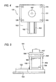
  • Fig. 4 is a plan view of the apparatus main body of Fig. 3.
  • Fig. 5 is a side view of the apparatus main body of Fig. 3.
  • Fig. 6 is a front view of the manufacturing apparatus (set with a lower mold die) for explaining a method of manufacturing a compound according to the invention.
  • Fig. 7 is a front view of the manufacturing apparatus (set with an outer part) for explaining a method of manufacturing a compound according to the invention.
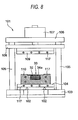
  • Fig. 8 is a front view of the manufacturing apparatus (set with a hollow particle) for explaining a method of manufacturing a compound according to the invention.
  • Fig. 9 is a front view of the manufacturing apparatus (set with an alumina filter) for explaining a method of manufacturing a compound according to the invention.
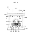
  • Fig. 10 is a front view of the manufacturing apparatus (set with a melt die) for explaining a method of manufacturing a compound according to the invention.
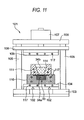
  • Fig. 11 is a front view of the manufacturing apparatus (upon charging a melt) for explaining a method of manufacturing a compound according to the invention.
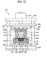
  • Fig. 12 is a front view of the manufacturing apparatus (set with an upper mold die, during press) for explaining a method of manufacturing a compound according to the invention.
  • Fig. 13 is a front view of the manufacturing apparatus (during pressurization with an inert gas) for explaining a method of manufacturing a compound according to the invention.
  • Fig. 14 is a front view of the manufacturing apparatus (upon taking out a product) for explaining a method of manufacturing a compound according to the invention.
  • Fig. 15 is an explanatory view of a manufacturing apparatus corresponding to the compound of Fig. 2.
  • Fig. 16 is an explanatory view of a state that the outer part is set up on the lower mold die, in the compound manufacturing apparatus of Fig. 15.
  • Fig. 17 is an explanatory view of a state that the outer part is charged with a hollow particle, in the compound manufacturing apparatus of Fig. 15.
  • Fig. 18 is an explanatory view of a compound manufacturing apparatus using a pipe-formed outer part worked by forming.
  • Figs. 19A and 19B are sectional views of the pipe-formed outer part worked by forming, wherein Fig. 19B is a perspective view of a compound manufactured by using the outer part of Fig. 19A.
  • Fig. 20 is an explanatory view of a manufacturing apparatus for a compound using an elongate-pipe-formed outer part.
  • Fig. 21 is a cross-sectional view of a compound using the elongate-pipe-formed outer part.
  • Fig. 22 is an explanatory view of a manufacturing apparatus for a compound using an elongate-pipe-formed outer part.
  • Fig. 23 is a sectional view of the compound using an elongate-pipe-formed outer part of Fig. 22.
  • Fig. 24 is a graph showing a relationship between a bending strength and a specific gravity of the compound.
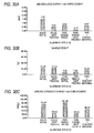
  • Figs. 25A, 25B and 25C are graphs showing a characteristic of a single content material wherein Fig. 25A is a graph of a bending strength during 1-mm displacement, Fig. 25B is a graph of a sample load and Fig. 25C is a graph of a specific strength during 1-mm displacement.
  • Figs. 26A, 26B and 26C are graphs showing a characteristic in using a pipe-formed outer part (SUS304 (t 0.2)) wherein Fig. 26A is a graph of a bending strength during 1-mm displacement, Fig. 26B is a graph of a sample load and Fig. 26C is a graph of a specific strength during 1-mm displacement.
  • Figs. 27A, 27B and 27C are graphs showing a characteristic in using a pipe-formed outer part (SUS304 (t 0.4)) wherein Fig. 27A is a graph of a bending strength during 1-mm displacement, Fig. 27B is a graph of a sample load and Fig. 27C is a graph of a specific strength during 1-mm displacement.
  • Figs. 28A, 28B and 28C are graphs showing a characteristic in using a pipe-formed outer part (SUS304 (t 0.6)) wherein Fig. 28A is a graph of a bending strength during 1-mm displacement, Fig. 28B is a graph of a sample load and Fig. 28C is a graph of a specific strength during 1-mm displacement.
  • Figs. 29A, 29B and 29C are graphs showing a characteristic in using a pipe-formed outer part (SUS304 (t 0.8)) wherein Fig. 29A is a graph of a bending strength during 1-mm displacement, Fig. 29B is a graph of a sample load and Fig. 29C is a graph of a specific strength during 1-mm displacement.
  • Figs. 30A, 30B and 30C are graphs showing a characteristic in using a pipe-formed outer part (aluminum 1070 (t 1.0)) wherein Fig. 30A is a graph of a bending strength during 1-mm displacement, Fig. 30B is a graph of a sample load and Fig. 30C is a graph of a specific strength during 1-mm displacement.
  • Figs. 31A, 31B and 31C are graphs showing a characteristic in using a pipe-formed outer part (SS (t 1.0)) wherein Fig. 31A is a graph of a bending strength during 1-mm displacement, Fig. 31B is a graph of a sample load and Fig. 31C is a graph of a specific strength during 1-mm displacement.
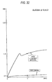
  • Fig. 32 is a graph of a bending strength during using a pipe-formed outer part (SUS304 (t 0.2)).
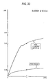
  • Fig. 33 is a graph of a bending strength during using a pipe-formed outer part (SUS304 (t 0.4)).
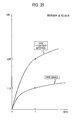
  • Fig. 34 is a graph of a bending strength during using a pipe-formed outer part (SUS304 (t 0.6)).
  • Fig. 35 is a graph of a bending strength during using a pipe-formed outer part (SUS304 (t 0.8)).
  • BEST MODE FOR CARRYING OUT THE INVENTION
    With reference to the drawings, embodiments of the present invention will be explained below. Figs. 1 and 2B are views showing one embodiment of a compound according to the invention, wherein Fig. 1A is a perspective view of an outer part while Fig. 1B is a perspective view of the compound structure.
    In Figs. 1 A and 1B, reference numeral 1 shows a compound to be suitably used in a structure requiring light weight and high strength. The compound 1 is structured with a metal outer part 3 having a hollow space 2 and a content material 4 formed in the hollow space 2. The outer part 3 has a desired exterior form, which herein has a desired wall thickness t and formed in a pipe form having smooth inner and outer surfaces. Meanwhile, the content material 4 is to reduce the weight and improve the strength of the compound 1, which herein is formed in a state filling the hollow space 2. The compound 1 like this, although explained later in detail with using another outer part than the outer part 3, is manufactured by a manufacturing apparatus structured, as described later, including an outer-part forming process and an inner-body forming process.
    The body in various kinds, according to the invention including the compound 1, is structured light in weight and high in strength, owing to the combination of an outer part and a content material formed in the hollow space of the outer part. For example, those are applicable as substitutes for structures, such as pipes, panels, cases and covers, presently used in broad technical fields. Namely, substitution is possible for the structures in broad technical fields including uprights such as of antenna poles, frames for bicycles and wheelchairs, automobile-body reinforcing members such as impact beams and tower bars, soundproof members, shield panel members, at-worksite foothold members, office-automating members, shield box members such as ECU cases and junction block covers, engine head cover members, aircrafts, shipping, railroad cars, space fields, harbor facilities, signal posts, ski poles, and so on.
    The outer part of the invention, including the outer part 3, is provided as a part forming an exterior shape as a product. The outer part is formed with various forms such as a pipe formed of a metal of stainless steel, aluminum, copper, iron, titanium, ceramics (pipe, plate molded member) or punched metal (mesh form), a pipe worked by forming, a plate formed of the foregoing metal, a press-worked plate by pressing, or joined ones of those by welding or so. Meanwhile, the outer part, having a hollow space, is formed to serve as a charge vessel for forming a content material. Incidentally, the hollow space may be formed by use of a separate member that can be removed after forming a content material (the separate member be explained later as a pin-like piece 110B-a in Figs. 18, 19A and 19B).
    The content material of the invention including the content material 4 is formed by using a moldable metal matrix melt and a filler contained in the melt. The metal matrix herein uses an aluminum die-cast alloy (e.g. ADC12 or the like, JIS Standard) (metal matrix may otherwise include Mg (magnesium)). The filler, intended for weight reduction and strength improvement, herein uses a light-weight filler, an inorganic filler or a fiber in various kinds. The light-weight filler includes, as an example, a hollow particle (ceramic hollow particle) of silica, alumina, mullite or the like (incidentally, the hollow particle is not limitative but a solid particle may be employed). Meanwhile, the fiber in various kinds includes a ceramic fiber, a ceramic whisker, a carbon fiber and a felt, as examples. The filler may be a mixture of two or more of the above examples.
    The compound may be manufactured by use of an outer part having an exterior shape as shown in Figs. 2A and 2B for example, besides structured with using the outer part 3 as in the compound 1 (a compound can be manufactured having an exterior shape suited to a product application). Fig. 2A and 2B are views showing another embodiment of a compound of the invention. Fig. 2A is a perspective view showing a compound that the outer part is formed in a cylindrical form having a rectangular section while Fig. 2B is a perspective view showing a compound that the outer part is formed by joining press-worked plates together.
    In Fig. 2A, a compound 11 having light weight and high strength is structured with a metal outer part 13 having a hollow space 12 and a content material 14 formed in the hollow space 12. The outer part 13 is a cylindrical member opened at both ends and having a rectangular section, whose interior is formed as a hollow space 12. Meanwhile, the content material 14 is formed of the same substance as the foregoing content material 4. The compound 11 is made lighter in weight than the solid structure having the same exterior shape formed of the metal material of the outer part 13. Furthermore, it has a higher strength than the outer part 13 single or the content material 14 single.
    In Fig. 2B, a compound 21 having light weight and high strength is structured with a metal outer part 23 having a hollow space 22 (see Fig. 16) and a content material 24 formed in the hollow space 22. The outer part 23 is structured with a plate 23b having an opening 23a for charging or pouring the filler and metal melt into the hollow space 22, and a press-worked plate 23d nearly in a boat form having a recess 23c. Meanwhile, the outer part 23 is formed by welding or merely contacting the plate 23b and the press-worked plate 23d together, as shown in the figure. The content material 24 is formed of the same as the foregoing content material 4. The compound 21 like this is made lighter in weight than the solid structure having the same exterior shape and of the metal material of the outer part 23. Furthermore, it is higher in strength than the outer part 23 single or the content material 14 single.
    Referring to Figs. 3 to 14, explanation is next made of an apparatus and method of manufacturing a compound of the invention. First explained is a manufacturing apparatus.
    A compound manufacturing apparatus in the invention, shown at reference numeral 101, is structured with a lower plate 103 having a pair of rails 102, 102 extending horizontally (in a front-rear direction), a slide plate 104 in a two-member structure for slide based on the one pair of rails 102, 102, a plurality of column supports 105 vertically extending and having one ends fixed to the lower plate 103, an upper plate 106 fixed on the other ends of the column supports 105, a cylinder 107 fixed on the upper plate 106, an intermediate plate 108 inserted over the column supports 105 and for vertical slide with expansion/contraction of the cylinder 107, a pressurizing plate fixed on the intermediate plate 108 and opposed to the slide plate 104, for example.
    Also, the manufacturing apparatus 101 is structured having a lower mold die 110, melt die 111 and upper mold die 112, set up between the opposed slide plate 104 and pressurizing plate 109.
    The lower mold die 110 is formed with an outer-part setter 113 for setting the outer part, and a fluid conduit port (air vent), not shown, communicating with the outer-part setter 113. A filter (not shown) is attached, for example, at an opening edge of the not-shown fluid conduit port.
    The melt die 111 is formed with a melt-charger 114 for charging the metal matrix melt. The melt charger 114 is formed nearly in a funnel form in a manner continuing with the outer-part setter 113. Incidentally, the opening formed in the outer part is formed in a position matched to the position of the melt charger 114. A gasket, not shown, is arranged in a region joining between the melt die 111 and the lower mold die 110.
    An argon-gas pressurizer 115 (not limited to argon gas) on the upper mold die 112. Meanwhile, the upper mold die 112 is formed with a piping 116 leading the gas pressure of from the argon-gas pressurizer 115 to the interior of the melt charger 114. The reference numeral 117, in the figure, represents a heater for use in heating.
    In the manufacturing apparatus 101, the lower mold die 110 is assumed corresponding to a first mold die set forth in the claim. Meanwhile, the melt die 111 is assumed corresponding to a second mold die, similarly. Meanwhile, the melt die 111 and upper mold die 112 is assumed corresponding to content material forming means, similarly. Meanwhile, the upper mold die 112 is assumed corresponding to melt impregnating means similarly. Meanwhile, the heater 117 is assumed corresponding to a heater, similarly.
    The compound manufacturing method based on the above structure is explained in one example thereof. First, performed is a process step to set up the lower mold die 110 on a predetermined position of slide plate 104, as shown in Fig. 6. At this time, the operation is naturally facilitated if the slide plate 104 is previously drawn frontward.
    Subsequently, after completing the setting up of lower mold die 110, performed is a process to set up an outer part 33 having hollow space 32 in the outer-part setter 113 of lower mold die 110 (corresponding to a second step set forth in the claim, the second step and subsequent herein agreeing with a content material forming step). Incidentally, the outer part 33 is assumed previously formed having a shape as shown in the figure in another process step (outer part forming step and first step set forth in the claim).
    Subsequently, after completing the setting up of outer part 33, performed is a process to charge a hollow particle 34a in the hollow space 32 of the outer part 33 (corresponding to a third step set forth in the claim). As for charging of a hollow particle 34a, employed suitably is a charge method (e.g. charging by the action of vibration, interrupted feed under pressure (cutting by putting in a bag of a material (e.g. paper or resin) to vanish due to contact with a melt), etc.). Incidentally, this is not true for the charge timing of a hollow particle 34a. Namely, it may be done before setting up the outer part 33 to the outer setter 113.
    Subsequently, after completing the charging of a hollow particle 34a, performed is a process step to set up an alumina filter 118 to an opening position of the outer part 33, as shown in Fig. 9. Then, after completing the setting up of the alumina filter 118, performed is a process step to set up a melt die 111 on the lower mold die 110, as shown in Fig. 10. At this time, the opening of outer part 33 and the melt charger 114 of melt die 111 are aligned together sandwiching the alumina filter 118.
    Subsequently, after completing the setting up of the lower mold die 110, performed is a process step to charge a metal-matrix melt 34b into the melt charger 114 of melt die 111, as shown in Fig. 11. As for melt 34b charge, a charge method is assumed suitably employed. Subsequently, after completing the charging of melt 34b, performed is a process step to set up an upper mold die 112 on the melt die 111, as shown in Fig. 12. At this time, the piping 116 in the upper mold die 112 is placed in communication with the melt charge 114 of the melt die 111. Also, due to an operating of the cylinder 107, the upper mold die 112 is urged by a descending pressurizing plate 109.
    Subsequently, after completing the setting of upper mold die 112, performed is a process step to actuate the argon-gas pressurizer 115 on the upper mold die 112 and pressurize the melt charger 114 of melt die 111 with argon gas thereby pouring the metal-matrix melt 34b charged in the melt charger 114 into the hollow space 32 of outer part 33 (the description so far corresponding to a fourth step set fourth in the claim), as shown in Fig. 13. At this time, the melt 34b poured in the hollow space 32 is impregnated in the hollow particle 34a, thereafter forming a content material 34.
    Subsequently, after completing the impregnation of melt 34b to the hollow particle 34a followed by forming a content material 34 to a certain extent of cooling, performed is a process step to remove the upper mold die 112 and melt die 111 to take a manufactured compound 31 out of the outer-part setter 113 of lower mold die 110 as shown in Fig. 14, and to remove the alumina filter 118 (corresponding to a fifth step set fourth in the claim).
    Incidentally, although not shown, the lower metal mold die 110 may be exchanged during the cooling, to pour a melt 34b through the melt die 111 into a hollow space of another outer part (not shown) set up on the another lower metal die (not shown) than that thereby forming a content material in the hollow space of the other outer part (not shown) (corresponding to a sixth step set forth in the claim). It is natural that productivity rate is to be improved by including this process step.
    Referring to Figs. 15 to 17, next explained is an apparatus for manufacturing the compound 21. Fig. 15 is an explanatory view of a manufacturing apparatus corresponding to the compound in Fig. 2B. Meanwhile, Fig. 16 is an explanatory view of a state the outer part is set up on the lower mold die while Fig. 17 is an explanatory view of a state that a hollow particle is charged in the outer part.
    In Fig. 15, the apparatus 101 A for manufacturing the compound 21 (see Fig. 2B) is in a structure that, basically, the lower mold die 110 of the foregoing manufacturing apparatus 101 is replaced with a lower mold die 110A as in the following wherein such a hold die as shown at reference numeral 119 is newly provided. The lower mold die 110A is formed with an outer-part setter 113A matched to the form of the outer part 23.
    As for manufacture of a compound 21, the outer part 23 is set up on the outer-part setter 113A, as shown in Fig. 16. Furthermore, as shown in Fig. 17, a hollow particle 24a is charged in the hollow space 22 and then an alumina filter 118 is set up on the outer part 23, on which the hold die 119 is further set up. Then, in case process steps are performed, in order, to set up the melt die 111 and the subsequent, manufacture is completed for a compound 21, having a light weight and high strength, structured with the outer part 23 and content material 24.
    Referring to Figs. 18, 19A and 19B, explanation is now made on a compound as another example and an apparatus for manufacturing such a compound. Fig. 18 is an explanatory view of a manufacturing apparatus for a compound using a pipe-formed outer part worked by forming. Fig. 19A is a sectional view of an outer part worked by forming while Fig. 19B is a perspective view of a compound using the outer part of Fig. 19A.
    In Figs. 18, 19A and 19B, the apparatus 101 B for manufacturing a compound 41 is basically structured that the lower mold die 110 of the foregoing manufacturing apparatus 101 is merely replaced with the following lower mold die 110B. The lower mold die 110B is formed with an outer-part setter 113B matched to the form of outer part 43. Meanwhile, in the lower mold die 110B, there is provided a pin-formed piece 110B-a inserted in the hollow space 42 of outer part 42 and for forming a through-hole 41 a in a compound 41.
    As for manufacture of a compound 21, the outer part 43 is set up on the outer-part setter 113B, and a hollow particle 44a is charged in the hollow space 42. Then, an alumina filter is set up on the outer part 43. Then, in case process steps are performed, in order, to set up a melt die 111 and the subsequent, manufacture is completed for a compound 41, having a light weight and high strength, structured with the outer part 43 and content material 44.
    Referring to Figs. 20 and 21, explanation is now made on a compound as still another example and an apparatus for manufacturing such a compound. Fig. 20 is an explanatory view of a manufacturing apparatus for a compound using an elongate-pipe-formed outer part. Fig. 21 is a sectional view of an elongate-pipe-formed outer part.
    In Figs. 20 and 21, an apparatus 101C for manufacturing a compound 41 is basically structured that the lower mold die 110 of the foregoing manufacturing apparatus 101 is merely replaced with the following lower mold die 110C. The lower mold die 110C is structured with a first lower mold die 110C-a, a second lower mold die 110C-b, a die hold member 110C-c and a heater 110C-d. Meanwhile, the lower mold die 110C is formed as a mold die having a split structure such that the first lower mold die 110C-a and the second lower mold die 11C-b can clamp the outer part 53 at its one and the other ends formed in the above form.
    The first lower mold die 110C-a and the second lower mold die 110C-b are respectively formed with outer-part setters 113C assuming a form capable of clamping the outer part 53. The second lower mold die 110C-b is formed with a fluid conduit port (air vent) 110C-e. The heater 110C-d uses induction heating so that the outer part 53 can be heated up directly.
    As for manufacture of a compound 51, the outer part 53 is set up at the respective outer-part setters 113C of the first lower mold die 110C-a and second lower mold die 110C-b, and a hollow particle is charged in a hollow space of the outer part 53. Then, a not-shown alumina filter is set up on the first lower mold die 110C-a. Then, in case process steps are performed, in order, to set up the melt die 111 and the subsequent, manufacture is completed for a compound 51, having a light weight and high strength, structured with the outer part 53 and content material 54.
    EMBODIMENT
    Now explained are the results of various evaluations made on a compound 61 manufactured by use of a manufacturing apparatus 131.
    Fig. 22 is an explanatory view of a manufacturing apparatus for a compound using a pipe-formed outer part, Fig. 23 is a cross-sectional view of a compound using a pipe-formed outer part, Fig. 24 is a graph showing a relationship between a strength and a specific gravity of a compound, Figs. 25A - 25C are graphs showing a characteristic of a single content material, Figs. 26A - 29C are graphs showing a characteristic in using a pipe-formed outer part, Figs. 30A - 30C are graphs showing a characteristic in using a pipe-formed outer part (aluminum 1070 (t1, 0)), Figs. 31A - 31C are graphs showing a characteristic in using a pipe-formed outer part (SS (t1, 0)), and Figs. 32 - 35 are graphs of a bending load.
    In Fig. 22, the manufacturing apparatus 131 is structured by setting up a lower mold die (first die) 132, melt die (second die) and upper mold die 134 between a slide plate and a pressurizing plate that are opposed to each other, in a manner similar to the foregoing manufacturing apparatus (This is true as to manufacturing process).
    The lower mold die 132 is formed with an outer-part setter 135 for setting up an outer part for a compound 61, and a fluid conduit port (air vent) 136 communicating with the outer-part setter 135. A filter (not shown) is attached at an opening edge of the fluid conduit port 136. In this embodiment, the lower mold die 132 has a mold-die temperature set at 540 °C.
    The melt die 133 is formed with a melt charger 137 for charging a metal-matrix melt 64a. The melt charger 137 is formed in a funnel form in a manner continuing with the outer-part setter 135. In this embodiment, the melt die 133 has a die temperature set at 700 °C. Meanwhile, the melt 64a has a temperature also set at 700 °C.
    A gasket 138 is arranged between the lower die 132 and the melt die 133. Meanwhile, a filter 139 is arranged between the outer-part setter 135 and the melt charger 137. The arrow in the figure represents a pressure-applying direction of argon gas. In this embodiment, the application pressure to argon gas is set at 392 - 980 kPa.
    In Figs. 22 and 23, the compound 61 manufactured by the manufacturing apparatus 131 is structured with a pipe-formed outer part 63 having a hollow 62, and a content material 64 formed in the hollow of the outer part 63.
    The outer part 63 uses any of materials of stainless steel (SUS304), aluminum (1070), iron (SS). Meanwhile, the outer part 63 is formed with a diameter 10 wherein the wall thickness t is in a range of t = 0.2 - 1.0. Furthermore, the outer part 63 is formed to 100 mm in the entire length thereof.
    The content material 64 is structured of a metal matrix and a light-weight filler. In this embodiment, the metal matrix uses an aluminum die-case alloy (ADC12 in JIS standard). Meanwhile, the light-weight filler is a hollow particle, blended with aluminum by 25 - 35%, iron oxide by 1 - 5% and titania by 0.5 - 1.5%, in a size of 10 - 350 µm.
    Figure 00210001
    Figure 00220001
    Figure 00230001
    As shown in Tables 1 to 3, the following samples were manufactured in a certain number. Namely, (1) manufactured was a sample of single content material 64 (single circular rod without having an outer part). (2) Meanwhile, samples were manufactured as single outer parts (single pipes of SUS304) having wall thickness of t = 0.2, t = 0.4, t = 0.6 and t = 0.8. (3) Meanwhile, samples were manufactured as to various composite bodies 61 whose content materials 64 were formed in the hollow spaces 2 of outer parts 63 (SUS304 pipes) having thickness of t = 0.2, t = 0.4, t = 0.6 and t = 0.8. (4) Besides, although not shown in Tables 1 to 3, manufactured were samples using outer parts 63 of aluminum 1070 (t = 1.0) and samples using outer parts 63 of SS (t = 1.0).
    Sample weights were measured for evaluations on the abive various samples. Meanwhile, measurements were made as to bending load during displacement by 1 mm of the sample. Furthermore, determined was specific tensile strength during displacement by 1 mm of the sample (bending load during 1-mm displacement/sample load).
    Fig. 24 is a graph showing a relationship between a bending strength and specific weight of a compound, wherein specific weight is shown on the abscissa while bending strength is on the ordinate. In this graph, plotting of aluminum 1070 (t = 1.0) single outer part 63 is made at around a specific gravity of 1.00. Using this as a benchmark, it can be known that the compound of the invention is so light in weight and high in strength by a comparison with other samples, by a comparison of a single SUS304 (t = 0.2) outer part 63 with a SUS304 (t = 0.2) compound 61, by a comparison of a single SUS304 (t = 0.4) outer part 63 with a SUS304 (t = 0.4) compound 61, by a comparison of a single SUS304 (t = 0.6) outer part 63 with a SUS304 (t = 0.6) compound 61 or by a comparison of a single SUS304 (t = 0.8) outer part 63 with a SUS304 (t = 0.8) compound 61. Incidentally, the reason why the bending strength of the compound 61 using the aluminum 1070 (t = 1.0) outer part 63 is not so high as compared with the bending strength of the aluminum 1070 (t = 1.0) single outer part 63 is because there is exhibited the effect of heat treatment upon the single outer part (see Figs. 30A - 30C).
    In Figs. 25A and 34, the bending load during 1-mm displacement was 0.73 kN (fracture before 1 mm displacement) on a single content material 64. Meanwhile, in Fig. 25B, sample weight was 10.68g on the single content material 64. Meanwhile, in Fig. 25C, the specific strength during 1-mm displacement was 68.35 N/g on the single content material 64.
    In Figs. 26A and 32, the bending load during 1-mm displacement was 0.11 kN on a single outer part 63 (SUS304 (t = 0.2), this is true in this column) and 1.37 kN on a compound 61 structured by an outer part 63 and a content material 64. Meanwhile, in Fig. 26B, sample weight was 62.05g on an SUS304 solid material, 4.86g on a single outer part 63, and 14.70g on a compound 61 structured by an outer part 63 and a content material 64. Meanwhile, in Fig. 26C, the specific strength during 1-mm displacement was 22.63 N/g on a single content material 63 and 93.20 N/g on a compound 61 structured by an outer part 63 and a content material 64. It can be seen that the compound 61 using an outer part 63 (SUS304 (t = 0.2) has a light weight and high strength.
    In Figs. 27A and 33, the bending load during 1-mm displacement was 0.39 kN on a single outer part 63 (SUS304 (t = 0.4), this is true in this column) and 2.00 kN on a compound 61 structured by an outer part 63 and a content material 64. Meanwhile, in Fig. 27B, sample weight was 62.05g on an SUS304 solid material, 9.53g on a single outer part 63, and 18.57g on a compound 61 structured by an outer part 63 and a content material 64. Meanwhile, in Fig. 27C, the specific strength during 1-mm displacement was 40.92 N/g on a single outer part 63 and 107.70 N/g on a compound 61 structured by an outer part 63 and a content material 64. It can be seen that the compound 61 using an outer part 63 (SUS304 (t = 0.4) has a light weight and high strength.
    In Figs. 28A and 34, the bending load during 1-mm displacement was 0.52 kN on a single outer part 63 (SUS304 (t = 0.6), this is true in this column) and 2.18 kN on a compound 61 structured by an outer part 63 and a content material 64. Meanwhile, in Fig. 28B, sample weight was 62.05g on an SUS304 solid material, 14.00g on a single outer part 63, and 22.27g on a compound 61 structured by an outer part 63 and a content material 64. Meanwhile, in Fig. 28C, the specific strength during 1-mm displacement was 37.14 N/g on a single outer part 63 and 97.89 N/g on a compound 61 structured by an outer part 63 and a content material 64. It can be seen that the compound 61 using an outer part 63 (SUS304 (t = 0.6) has a light weight and high strength.
    In Figs. 29A and 35, the bending load during 1-mm displacement was 1.12 kN on a single outer part 63 (SUS304 (t = 0.8), this is true in this column) and 2.58 kN on a compound 61 structured by an outer part 63 and a content material 64. Meanwhile, in Fig. 28B, sample weight was 62.05g on an SUS304 solid material, 18.27g on a single outer part 63, and 25.81 g on a compound 61 structured by an outer part 63 and a content material 64. Meanwhile, in Fig. 29C, the specific strength during 1-mm displacement was 61.30 N/g on a single outer part 63 and 99.96 N/g on a compound 61 structured by an outer part 63 and a content material 64. It can be seen that the compound 61 using an outer part 63 (SUS304 (t = 0.8) has a light weight and high strength. Incidentally, from the above result, the outer 63 is given a more preferable wall thickness t = 0.4 or greater.
    In Fig. 30A, the bending load during 1-mm displacement was 1.60 kN on an aluminum 1070 (t = 1.0) solid material (solid circular rod and without having an outer part) before heat treatment, 0.51 kN on the solid material after heat treatment, 0.62 kN on a single outer part 63 (aluminum 1070 (t = 1.0), this is true for this column) before heat treatment, 0.17 kN on the single outer part 63 after heat treatment, and 0.67 kN on a compound 61 structured by an outer part 63 and a content material 64 after heat treatment. Meanwhile, in Fig. 30B, sample weight was 21.21 g on a solid material before heat treatment, 21.21 g on a solid material after heat treatment, 7.62g on a single outer part 63 before heat treatment, 7.62g on the single outer part 63 after heat treatment, and 14.45g on a compound 61 structured by an outer part 63 and a content material 64. Meanwhile, in Fig. 30C, the specific strength during 1-mm displacement was 75.44 N/g on a solid material before heat treatment, 24.05 N/g on the solid material after heat treatment, 81.36 N/g on a single outer part 63 before heat treatment, 22.31 N/g on a single outer part 63 after heat treatment, and 46.37 on a compound 61 structured by a single outer part 63 after heat treatment and a content material 64.
    In Fig. 31 A, the bending load during 1-mm displacement was 1.40 kN on a single outer part 63 (SS (t = 1.0), this is true in this column) and 2.65 kN on a compound 61 structured by an outer part 63 and a content material 64. Meanwhile, in Fig. 31 B, sample weight was 60.08g on an SS solid material, 21.63g on a single outer part 63, and 28.47g on a compound 61 structured by an outer part 63 and a content material 64. Meanwhile, in Fig. 30C, the specific strength during 1-mm displacement was 64.72 N/g on a single outer part 63 and 93.08 N/g on a compound 61 structured by an outer part 63 and a content material 64. It can be seen that the compound 61 using an outer part 63 (SS (t = 1.0) has a light weight and high strength.
    As explained so far while referring to Figs. 1A to 35, the present invention can provide a compound light in weight and high in strength and a method and apparatus for manufacturing such a compound.
    Besides, the invention, of course, is to be practiced in various ways changed within the scope not departing from the gist of the invention.
    INDUSTRIAL APPLICABILITY
    As explained so far, the present invention is to exhibit an effect that can provide a method of manufacturing a compound light in weight and high in strength. Meanwhile, there is exhibited an effect that can provide an apparatus for manufacturing a compound light in weight and high in strength. Also, the invention is to exhibit an effect that can provide a compound light in weight and high in strength. The invention is to exhibit an effect that can improve the productivity rate. Meanwhile, the invention set forth in the other claim than the above is to provide an effect that can further improve the weight reduction and strength improvement for the compound.

    Claims (28)

    1. A method of manufacturing a compound, comprising:
      an outer part forming step of forming a metal outer part in a predetermined exterior form having a hollow space; and
      a content material forming step of forming a content material in the hollow space by using a metal matrix melt to be die-molded and a filler contained in the melt.
    2. A method of manufacturing a compound according to claim 1, wherein the outer part is to be heated up by using induction heating.
    3. A method of manufacturing a compound according to claim 1, wherein the filler uses a hollow particle or a particle:
    4. A method of manufacturing a compound according to claim 1, wherein the filler uses a reinforcing fiber or a felt.
    5. A method of manufacturing a compound according to claim 1, wherein the filler uses a mixture of two or more of a hollow particle, a particle, a reinforcing fiber and a felt.
    6. A method of manufacturing a compound, comprising:
      a first step of forming a metal outer part in a predetermined form having a hollow space;
      a second step of setting up the outer part on an outer part setter of a first mold die;
      a third step of charging a filler in the hollow space by a predetermined charging manner;
      a fourth step of charging a metal matrix melt to be die-molded into a second mold die and pouring the melt from the second mold die into the hollow space of the outer part set up on the first mold die so that the melt can be impregnated in the filler, thus forming a content material; and
      a fifth step of taking the outer part out of the first mold die after cooling down the content material formed.
    7. A method of manufacturing a compound according to claim 6, further comprising a sixth step of pouring the melt from the second mold die into a hollow space of another outer part set up on another first mold die different from the first mold die before moving to the fifth step after executing the fourth step, and forming a content material in the hollow space in the other outer part.
    8. A method of manufacturing a compound according to claim 6, wherein the outer part is heated up by using induction heating.
    9. A method of manufacturing a compound according to claim 6, wherein the filler uses a hollow particle or a particle.
    10. A method of manufacturing a compound according to claim 6, wherein the filler uses a reinforcing fiber or a felt.
    11. A method of manufacturing a compound according to claim 6, wherein the filler uses a mixture of two or more of a hollow particle, a particle, a reinforcing fiber and a felt.
    12. An apparatus for manufacturing a compound, comprising:
      a first mold die having an outer part setter for setting up a metal outer part in a desired exterior form having a hollow space; and
      content material forming means for forming a content material in the hollow space by using a metal matrix melt to be die-molded and a filler contained in the melt.
    13. An apparatus for manufacturing a compound according to claim 12, wherein the heater for heating up the outer part is structured by using induction heating.
    14. An apparatus for manufacturing a compound according to claim 13, wherein a gasket is arranged between the first mold die and the second mold die, and a filter is arranged between the outer part set up on the outer part setter and the melt charger.
    15. An apparatus for manufacturing a compound according to claim 14, wherein a filter is further arranged between the outer part and a fluid conduit port communicating with the outer part setter.
    16. An apparatus for manufacturing a compound, comprising:
      a first mold die formed with an outer part setter for setting up a metal outer part in a desired exterior form having a hollow space in which a filler can be charged by a predetermined charge manner;
      a second mold die formed with a melt charger for charging a metal matrix melt to be die-molded; and
      melt impregnating means for pouring the melt from the melt charger into the hollow space of the outer part set up on the outer part setter, and forming a content material by impregnating the melt in the filler.
    17. An apparatus for manufacturing a compound according to claim 16, wherein the first mold die is structured in plurality so that the melt can be poured therein, in order, from the melt charger.
    18. An apparatus for manufacturing a compound according to claim 16, wherein a heater for heating up the outer part is structured by using induction heating.
    19. An apparatus for manufacturing a compound according to claim 16, wherein a gasket is arranged between the first mold die and the second mold die, and a filter is arranged between the outer part set up on the outer part setter and the melt charger.
    20. An apparatus for manufacturing a compound according to claim 19, wherein a filter is further arranged between the outer part and a fluid conduit port communicating with the outer part setter.
    21. A compound characterized by comprising:
      a metal outer part in a desired exterior form having a hollow space; and
      a content material formed in the hollow space by using a metal matrix melt to be die-molded and a filler contained in the melt.
    22. A compound according to claim 21, wherein the filler uses a hollow particle or a particle.
    23. A method of manufacturing a compound according to claim 21, wherein the filler uses a reinforcing fiber or a felt.
    24. A method of manufacturing a compound according to claim 21, wherein the filler uses a mixture of two or more of a hollow particle, a particle, a reinforcing fiber and a felt.
    25. A compound characterized in that:
      a metal matrix melt to be die-molded is impregnated in the filler, a metal outer part in a desired form having a hollow space being provided as a part forming an exterior form as a charge vessel and as a product as to the filler and the melt.
    26. A compound according to claim 25, wherein the filler uses a hollow particle or a particle.
    27. A method of manufacturing a compound according to claim 25, wherein the filler uses a reinforcing fiber or a felt.
    28. A method of manufacturing a compound according to claim 25, wherein the filler uses a mixture of two or more of a hollow particle, a particle, a reinforcing fiber and a felt.
    EP04700171A 2003-01-06 2004-01-05 METHOD FOR MANUFACTURING COMPOUND BODY, DEVICE FOR MANUFACTURING COMPOUND BODY, AND COMPOUND BODY Withdrawn EP1595623A4 (en)

    Applications Claiming Priority (3)

    Application Number Priority Date Filing Date Title
    JP2003000392 2003-01-06
    JP2003000392A JP2004261812A (en) 2003-01-06 2003-01-06 Composite manufacturing method, composite manufacturing apparatus, and composite
    PCT/JP2004/000005 WO2004060592A1 (en) 2003-01-06 2004-01-05 Compound body manufacturing method, compound body manufacturing device, and compound body

    Publications (2)

    Publication Number Publication Date
    EP1595623A1 true EP1595623A1 (en) 2005-11-16
    EP1595623A4 EP1595623A4 (en) 2007-02-07

    Family

    ID=32708772

    Family Applications (1)

    Application Number Title Priority Date Filing Date
    EP04700171A Withdrawn EP1595623A4 (en) 2003-01-06 2004-01-05 METHOD FOR MANUFACTURING COMPOUND BODY, DEVICE FOR MANUFACTURING COMPOUND BODY, AND COMPOUND BODY

    Country Status (6)

    Country Link
    US (1) US20060213064A1 (en)
    EP (1) EP1595623A4 (en)
    JP (1) JP2004261812A (en)
    KR (1) KR20050103468A (en)
    AU (1) AU2004203713A1 (en)
    WO (1) WO2004060592A1 (en)

    Cited By (1)

    * Cited by examiner, † Cited by third party
    Publication number Priority date Publication date Assignee Title
    EP2420335A1 (en) * 2010-08-20 2012-02-22 Hofmann Ceramic GmbH Method for producing a ceramic metal matrix compound material and a moulded part produced according to this method

    Families Citing this family (3)

    * Cited by examiner, † Cited by third party
    Publication number Priority date Publication date Assignee Title
    US10364195B2 (en) 2014-07-28 2019-07-30 Rolls-Royce Corporation Braze for ceramic and ceramic matrix composite components
    US20160280609A1 (en) * 2015-03-23 2016-09-29 Rolls-Royce Corporation Self-propagating braze
    US10293424B2 (en) 2015-05-05 2019-05-21 Rolls-Royce Corporation Braze for ceramic and ceramic matrix composite components

    Family Cites Families (9)

    * Cited by examiner, † Cited by third party
    Publication number Priority date Publication date Assignee Title
    US2481025A (en) * 1945-12-15 1949-09-06 Westinghouse Electric Corp Method of making shafts having sheet metal journal surfaces
    JPS60115361A (en) * 1983-11-25 1985-06-21 Toyota Motor Corp Production of composite material
    JPS61130745U (en) * 1985-02-04 1986-08-15
    JPS62161463A (en) * 1986-01-13 1987-07-17 Nippon Kokan Kk <Nkk> Manufacturing method of metal matrix composite material
    JPH01287242A (en) * 1988-05-11 1989-11-17 Hitachi Ltd Surface modified parts and their manufacturing method
    JPH04182055A (en) * 1990-11-14 1992-06-29 Nippon Steel Corp Method for forging molten metal
    JPH1129831A (en) * 1997-07-10 1999-02-02 Nichias Corp Preform for metal matrix composite and method for producing the same
    US6019158A (en) * 1998-05-14 2000-02-01 Howmet Research Corporation Investment casting using pour cup reservoir with inverted melt feed gate
    JP3458832B2 (en) * 2000-08-01 2003-10-20 株式会社豊田自動織機 Manufacturing method of composite material

    Cited By (1)

    * Cited by examiner, † Cited by third party
    Publication number Priority date Publication date Assignee Title
    EP2420335A1 (en) * 2010-08-20 2012-02-22 Hofmann Ceramic GmbH Method for producing a ceramic metal matrix compound material and a moulded part produced according to this method

    Also Published As

    Publication number Publication date
    KR20050103468A (en) 2005-10-31
    US20060213064A1 (en) 2006-09-28
    WO2004060592A1 (en) 2004-07-22
    EP1595623A4 (en) 2007-02-07
    AU2004203713A1 (en) 2004-07-22
    JP2004261812A (en) 2004-09-24

    Similar Documents

    Publication Publication Date Title
    EP0110097B1 (en) Method and apparatus for manufacturing composite material using pressure chamber and casting chamber
    CN103648683A (en) Multi-alloy vertical semi-continuous casting method
    CN101423904B (en) A method for manufacturing high-volume particle-reinforced metal-matrix composite pipes
    CN86107495A (en) The casting mold and the casting method of product made in the hollow belt uphill casting
    CN109130748A (en) The split type I type distance rod of aluminium alloy and its casting and forming and overall thermal riveting assembly method
    JP2002529249A (en) Methods and devices for chill molding
    EP1595623A1 (en) Compound body manufacturing method, compound body manufacturing device, and compound body
    JP3041421B1 (en) Ceramic reinforced metal matrix composite and method for producing the same
    US5207263A (en) VLS silicon carbide whisker reinforced metal matrix composites
    Pados et al. Fabrication of In-situ Syntactic Aluminium Foam-Filled Steel Tubes
    US4606884A (en) Composite billet for hot transformation
    JPS58215263A (en) Production of composite material
    Ruutopold et al. The role of interfaces in the application of rapidly solidified metal ribbons as reinforcements for composites
    JPH0378177B2 (en)
    JPS60191654A (en) Piston for internal-combustion engine and production thereof
    Neussl et al. Selectively fibre-reinforced components produced by the modified investment casting process
    JPS62185844A (en) Production of fiber reinforced metallic composite material
    JPH083661A (en) Aluminum alloy cylinder tube and method of manufacturing the same
    JPS5870963A (en) Easy-to-weld composite material and its production
    JPS62149831A (en) Manufacture of fiber-reinforced metallic composite material
    JP2976437B2 (en) Manufacturing method of metal matrix composite material
    CN2598725Y (en) Leak proof ditch plate shaping mould and vibration platform
    JPS623862A (en) Joining method for fiber reinforced metal base composite material
    Druschitz et al. Advanced lost foam casting processes and materials
    JPS60177140A (en) Composite metallic material and its production

    Legal Events

    Date Code Title Description
    PUAI Public reference made under article 153(3) epc to a published international application that has entered the european phase

    Free format text: ORIGINAL CODE: 0009012

    17P Request for examination filed

    Effective date: 20050802

    AK Designated contracting states

    Kind code of ref document: A1

    Designated state(s): AT BE BG CH CY CZ DE DK EE ES FI FR GB GR HU IE IT LI LU MC NL PT RO SE SI SK TR

    AX Request for extension of the european patent

    Extension state: AL LT LV MK

    RBV Designated contracting states (corrected)

    Designated state(s): AT BE BG CH CY CZ DE DK EE ES FI FR GB GR HU IE IT LI LU MC NL PT RO SE SI SK TR

    DAX Request for extension of the european patent (deleted)
    RBV Designated contracting states (corrected)

    Designated state(s): DE FR GB

    A4 Supplementary search report drawn up and despatched

    Effective date: 20070108

    RIC1 Information provided on ipc code assigned before grant

    Ipc: B22D 19/14 20060101AFI20070102BHEP

    STAA Information on the status of an ep patent application or granted ep patent

    Free format text: STATUS: THE APPLICATION HAS BEEN WITHDRAWN

    18W Application withdrawn

    Effective date: 20070402