EP1595480B1 - Machine à café automatique - Google Patents
Machine à café automatique Download PDFInfo
- Publication number
- EP1595480B1 EP1595480B1 EP05009804A EP05009804A EP1595480B1 EP 1595480 B1 EP1595480 B1 EP 1595480B1 EP 05009804 A EP05009804 A EP 05009804A EP 05009804 A EP05009804 A EP 05009804A EP 1595480 B1 EP1595480 B1 EP 1595480B1
- Authority
- EP
- European Patent Office
- Prior art keywords
- motor
- axis
- brewing
- closure piece
- pivot column
- Prior art date
- Legal status (The legal status is an assumption and is not a legal conclusion. Google has not performed a legal analysis and makes no representation as to the accuracy of the status listed.)
- Active
Links
- 235000013353 coffee beverage Nutrition 0.000 title claims abstract description 87
- 235000016213 coffee Nutrition 0.000 title claims abstract description 83
- 230000033001 locomotion Effects 0.000 claims description 49
- 239000000843 powder Substances 0.000 claims description 34
- 230000005540 biological transmission Effects 0.000 claims description 20
- 238000012546 transfer Methods 0.000 description 23
- XLYOFNOQVPJJNP-UHFFFAOYSA-N water Substances O XLYOFNOQVPJJNP-UHFFFAOYSA-N 0.000 description 14
- 230000000630 rising effect Effects 0.000 description 9
- 238000013124 brewing process Methods 0.000 description 7
- 238000000034 method Methods 0.000 description 5
- 230000008901 benefit Effects 0.000 description 4
- 230000008569 process Effects 0.000 description 4
- 230000007704 transition Effects 0.000 description 4
- 241000533293 Sesbania emerus Species 0.000 description 3
- 230000009471 action Effects 0.000 description 3
- 238000004140 cleaning Methods 0.000 description 3
- 238000012549 training Methods 0.000 description 3
- 238000010276 construction Methods 0.000 description 2
- 230000008878 coupling Effects 0.000 description 2
- 238000010168 coupling process Methods 0.000 description 2
- 238000005859 coupling reaction Methods 0.000 description 2
- 230000002950 deficient Effects 0.000 description 2
- 238000005553 drilling Methods 0.000 description 2
- 238000004519 manufacturing process Methods 0.000 description 2
- 239000000203 mixture Substances 0.000 description 2
- 238000003825 pressing Methods 0.000 description 2
- 238000005452 bending Methods 0.000 description 1
- 230000015572 biosynthetic process Effects 0.000 description 1
- 238000009414 blockwork Methods 0.000 description 1
- 235000020289 caffè mocha Nutrition 0.000 description 1
- 235000015116 cappuccino Nutrition 0.000 description 1
- 230000001427 coherent effect Effects 0.000 description 1
- 230000007547 defect Effects 0.000 description 1
- 238000013461 design Methods 0.000 description 1
- 238000007599 discharging Methods 0.000 description 1
- 230000000694 effects Effects 0.000 description 1
- 230000003993 interaction Effects 0.000 description 1
- 238000002360 preparation method Methods 0.000 description 1
- 238000012545 processing Methods 0.000 description 1
- 238000003860 storage Methods 0.000 description 1
- 230000001960 triggered effect Effects 0.000 description 1
Images

Classifications
-
- A—HUMAN NECESSITIES
- A47—FURNITURE; DOMESTIC ARTICLES OR APPLIANCES; COFFEE MILLS; SPICE MILLS; SUCTION CLEANERS IN GENERAL
- A47J—KITCHEN EQUIPMENT; COFFEE MILLS; SPICE MILLS; APPARATUS FOR MAKING BEVERAGES
- A47J31/00—Apparatus for making beverages
- A47J31/24—Coffee-making apparatus in which hot water is passed through the filter under pressure, i.e. in which the coffee grounds are extracted under pressure
- A47J31/34—Coffee-making apparatus in which hot water is passed through the filter under pressure, i.e. in which the coffee grounds are extracted under pressure with hot water under liquid pressure
- A47J31/36—Coffee-making apparatus in which hot water is passed through the filter under pressure, i.e. in which the coffee grounds are extracted under pressure with hot water under liquid pressure with mechanical pressure-producing means
- A47J31/3604—Coffee-making apparatus in which hot water is passed through the filter under pressure, i.e. in which the coffee grounds are extracted under pressure with hot water under liquid pressure with mechanical pressure-producing means with a mechanism arranged to move the brewing chamber between loading, infusing and ejecting stations
- A47J31/3609—Loose coffee being employed
- A47J31/3614—Means to perform transfer from a loading position to an infusing position
-
- A—HUMAN NECESSITIES
- A47—FURNITURE; DOMESTIC ARTICLES OR APPLIANCES; COFFEE MILLS; SPICE MILLS; SUCTION CLEANERS IN GENERAL
- A47J—KITCHEN EQUIPMENT; COFFEE MILLS; SPICE MILLS; APPARATUS FOR MAKING BEVERAGES
- A47J31/00—Apparatus for making beverages
- A47J31/44—Parts or details or accessories of beverage-making apparatus
- A47J31/4403—Constructional details
Definitions
- the invention relates to a coffee machine machine, in particular for Einzeltassen- and Kännchenfertigung, with at least one device for supplying coffee powder, with a brewing device having a stationary arranged from a vertical axis pipe section and two closure pieces brewing chamber, with a combined axial and pivoting drive with a motor, a downstream transmission and an axially movable and rotatable pivoting column for the movement of the upper, fixed to a rotary arm closure piece in a brewing position in and out of the pipe section, for the movement of the upper closure piece in a parking position outside the axis of the pipe section and in a standby position in the axis of the pipe section, with a further motor, a further downstream transmission and an axially movable spindle having vertical drive for the lower closure piece , and with a powered swivel scraper for the removal of the tablet from coffee powder.
- the coffee machine usually also has a pivotable funnel for facilitating the introduction of the coffee powder in the brewing chamber.
- a coffee machine machine is understood to mean a machine in which the operations of grinding the coffee powder, introducing the coffee powder into the brewing chamber, the brewing process itself and the ejection of the leached coffee powder in the form of pushing out the leached and squeezed tablet of coffee powder automatically without one of these or further process steps would have to be manually triggered or supported. It is understood, however, that the coffee maker must be started to perform a cycle by pressing a switch or the like. The invention is also applicable to a batch fresh brewing machine.
- a coffee machine of the type described above is from the EP 0 641 536 B1 known.
- the coffee machine has a brewing device, which has a brewing chamber, which consists of a stationarily arranged with a vertical axis pipe section - also called brewing tube - and two closure pieces is formed. It is an axial drive for the movement of the upper closure piece on a rotary arm into and out of the pipe section.
- a pivot drive serves to move the upper closure piece into a parking position outside the axis of the pipe section and into a standby position in the axis of the pipe section. The axial and the pivot drive for the upper closure piece are combined.
- the combined axial and pivot drive comprises a motor connected behind a worm gear and an axially movable and rotatable pivot column for the movement of the upper, fixedly arranged on the rotary arm closure piece in a brewing position in and out of the pipe section, for the movement of the upper closure piece in the parking position outside the axis of the pipe section and in the standby position in the axis of the pipe section.
- the upper locking piece is firmly connected to the rotary arm.
- the transfer case is arranged above the worm gear and has a guide bushing surrounding the pivoting column, a grooved bushing surrounding the guide bushing, a bolt and a sliding block.
- the Nutbuchse is fixedly mounted in the housing and has for this purpose a bore into which the bolt engages, which is screwed radially from outside to inside the housing.
- the bolt also passes through the guide bushing in the region of a slot extending radially over part of the circumference.
- the stationary grooved bush is provided with a slide.
- the slideway has at its lower end to an axially parallel beginning region, followed by a thread-like rising area connects.
- the guide bush also has a slideway, which runs parallel to the axis. With the two slides in the Nutbuchse and in the guide bush, the sliding block works together, which is screwed into the pivot column.
- This transfer case constructed in this way has a relatively large number of individual parts and is complicated and expensive to manufacture and to assemble.
- the known coffee machine machine already provides a combined axial and rotary drive for the upper closure piece and a separate vertical drive for the lower closure piece, so that on the one hand the two closure pieces can be moved independently of each other relative to the pipe section of the brewing chamber in order to advantageously pre-press, relieve and to be able to lift the tablet from coffee powder.
- For the upper closure piece is no disadvantage in the individual phases of the brewing cycle.
- All lifting and pivoting movements of the upper closure piece are derived from this one combined drive by means of the transfer case.
- the individual movements can be determined very accurately and reproducibly. This relieves the control unit.
- Some movements are forcibly mechanically coupled via the transfer case, which not only simplifies the control unit, but also advantageously increases the reliability.
- the transfer case the individual movements of the upper closure piece and the swivel scraper can be derived from a drive and coordinated with each other. Fewer sensors are required, and the forced mechanical coupling of the movements proves advantageous.
- the scraper action is coupled with the opening movement, that is, the pivoting from the ready position to the parking position. It is not necessary to realize and drive a coffee feeder.
- the brewing chamber is freely accessible from above.
- a vertical drive for the lower closure piece which has, in addition to a further motor, a downstream further worm gear and an axially guided spindle.
- the spindle carries the lower closure piece of the brewing chamber.
- the further worm gear is arranged below the lower closure piece. If the seal of the lower closure piece of the brewing chamber becomes defective, there is a risk that a mixture of coffee and coffee powder enters the worm gear and even further into the motor of the vertical drive. Also, the worm gear and the motor of the combined axial and rotary actuator can be damaged because the two worm drives and the two motors form a unit enclosed by a common housing.
- the upper closure piece of the brewing device is arranged on a rotary arm, which is pivotable about a stationary bearing.
- the upper closure piece is pivotable with the rotary arm from a standby position in the axis of the pipe section above the Brühraums in a parking position outside the axis of the pipe section, wherein a pivot drive in the form of an electric motor with downstream worm gear is provided for this pivoting.
- On the rotary arm an axial drive is further arranged, by means of which the upper closure piece for reaching the brewing position from the standby position in the pipe section is sealingly retractable.
- the known coffee machine on a vertical drive for the lower closure piece.
- the invention has for its object to reduce the construction cost of a coffee machine of the type described above, in particular with regard to the transfer case and / or the drives, and at the same time to simplify the brewing cycle, without the advantages of Vorverêtns, relieving and pushing out and the removal of the Having to dispense tablet from coffee powder.
- the slideway with the axis-parallel starting area for transferring the upper closure piece from the brewing position to the standby position and the thread-like rising area for pivoting the rotary arm with the upper closure piece from the ready position to the park position is no longer on the Nutbuchse but on the pivot column of the combined Axial and rotary actuator of the rotary arm provided.
- it is only necessary that the sliding block engaging in the sliding block is fixedly provided on the housing.
- the grooved bushing and the bolt passing through the grooved bushing and the bushing are eliminated.
- the guide bushing no longer needs to be housed radially between the pivot column and grooved bushing.
- the guide bush can shrink into an axially offset guide ring to be arranged.
- the pivotal movement of the funnel and the Schwenkabstreifers can be derived from the guide ring.
- the guide ring is offset axially relative to the slide and the sliding block and expediently arranged above these elements surrounding the pivot column.
- the guide ring is rotatably connected to the pivot column, but axially slidably connected, so that the guide ring with the seated Schwenkabstreifer and funnel in a purely axial movement of the pivot column performs no movement, but follows the pivot column in a rotary motion.
- the transfer case as a whole has so a reduced number of items and is so inexpensive in production and assembly.
- the transfer case advantageously has a reduced diameter and a reduced space.
- the invention can also be used in conjunction with a water heater, i. It is possible, in particular to surround the brewing chamber with a water heater to ensure a quick operational readiness of the coffee machine. Both motors can be arranged below the water heater, that is, at a location that is not so highly thermally stressed.
- the housing of the water heater can at the same time also form the housing of the brewing chamber and the housing of the transfer case, so that the separate arrangement of housings is eliminated.
- this common housing takes on the pipe section of the brewing chamber. There is thus only a large housing formed from a coherent piece, the relatively accurate processing brings no problems.
- the accuracy that is required for positioning the parts relative to one another is achieved automatically. In particular, the distance of the axis of the brewing chamber to the axis of the transfer case is fixed.
- a first motor should be provided with its axis independent of the vertical drive for the lower closure piece, in particular above a first gear, parallel and spaced from the axis of the rotary arm .
- the independence refers to the realization of separate units of one motor and one transmission gear for the combined axial and pivot drive on the one hand and the vertical drive on the other.
- a common housing or a common Auflagerung is deliberately avoided.
- the respective engine is arranged higher than the associated transmission gear, so that even with defective seal on the lower closure piece of the brewing chamber, a mixture of coffee and coffee powder can not affect the engine.
- the individual elements of the two units can be inexpensively replaced or repaired independently of each other.
- a second motor is independent of the first motor, in particular with its axis above a second transmission gear, parallel and spaced from the axis of the brewing chamber provided.
- Both engines are mounted on one console each. On a common housing is deliberately omitted.
- the individual elements of the drives are service-friendly, so easily accessible and visible housed.
- the independent training and arrangement of the separate units of one motor and one downstream transmission gear for the combined axial and pivot drive on the one hand and the vertical drive on the other hand is also independent inventive importance, d. H. they can be realized in connection with the formation of the transfer case, but also independently.
- the transfer case can be designed so that during the movement of the upper closure piece from the standby position to the parking position and the Schwenkabstreifer dissipates the tablet of coffee powder.
- the Schwenkabstreifer is not connected to the rotary arm, but stored separately, so that its movement can be removed separately.
- the movement of the upper closure piece on the one hand and the Schwenkabstreifers on the other hand matched and coupled via the transfer case. This coupling is carried out so that the direction of the stripping movement coincides with the direction of pivoting of the upper closure piece from the ready position to the parking position.
- the first gear and / or the second motor downstream transmission gear can advantageously have a toothed belt, a V-belt or a gear stage.
- at least the transmission gear for the vertical drive for coffee and coffee powder should be permeable.
- a bevel gear is conceivable at this point.
- both transmission gears are formed with matching elements. This is advantageous depending on a mother, which is rotatably mounted, but axially immovable.
- the nut has an internal thread which cooperates with an external thread on the spindle of the vertical drive or on the pivot column of the combined axial and pivot drive. On the outer circumference of the nut z. B. the timing belt.
- a guide ring In the upper part of the pivot column, a guide ring should be rotatable, but axially non-displaceable, which is rotatably coupled to the pivot column, but axially displaceable coupled.
- the Schwenkabstreifer for the removal of the tablet of coffee powder and / or the funnel for the introduction of the coffee powder in the brewing chamber are rotatably connected to the guide ring.
- the guide ring has only a small axial extent and therefore requires a small space. Nevertheless, it fulfills all the necessary functions with regard to the pivotability of the swivel scraper and the funnel. Between the pivot column and the guide ring a non-circular connection is provided.
- the slideway in the Nutbuchse has an axis-parallel starting area for the transfer of the upper closure piece from the brewing position in the standby position and vice versa.
- a rotational movement of the pivoting column is prevented and an axis-parallel lifting movement is ensured.
- This must be done at least in the area in which the upper closure piece is located in the pipe section of the brewing chamber.
- a smooth transition between this area and the thread-like rising area makes sense.
- the thread-like rising area puts the rotary arm with the upper closure piece fixedly arranged in a pivoting movement from the ready position to the parking position and vice versa.
- the upper closure piece moves away from the axis of the pipe section, so that the space above the pipe section becomes free.
- the ready position is arranged at a comparatively lower altitude than the parking position, so that outflow chutes of coffee grinders above the pipe section in the standby position can be easily driven under.
- the relative lifting of the upper closure piece into the parking position is advantageous insofar as a shower position for cleaning the upper closure piece by ejecting an appropriate amount of water becomes possible. This shower water can be discharged through a drain and thus does not reach the brewing room.
- the Schwenkabstreifer is located behind the upper closure piece, ie it follows in the pivoting of the upper closure piece from the standby position in the park position this after.
- the Schwenkabstreifer is expediently formed approximately semicircular curved, wherein the concave side is associated with the upper closure piece. This makes it possible to use when transferring the upper closure piece from the standby position in the parking position at the same time also the Schwenkabstreifer for discharging the tablet, without this makes the brewing cycle more complicated.
- the non-circular connection between the guide ring and the pivot column can be arranged expediently axially parallel. It runs in a straight line and is easy to produce. The rotational movement is taken from the thread-like rising portion of the slide in the pivot column.
- the rotary arm is extended beyond the pivot column on the side facing away from the upper closure piece and has a stop.
- a stop associated counter-stop is provided, on which the stop of the rotary arm is supported in the brewing position of the upper closure piece.
- the stop or the counter-stop can be designed to be adjustable, so that thus the position of the upper closure piece is set in the brewing position. If pressure acts on the upper closure piece during the brewing process in the brewing space, a corresponding counterforce can be received between the stop and the counterstop, so that ultimately the pivoting column is kept free from bending stress. This benefits their storage, reliability and longevity.
- the guide ring can also form the bearing for the pivot column.
- the Schwenkabstreifer is rotatably connected to the guide ring, in particular screwed so that each rotation of the guide ring is transmitted to the Schwenkabstreifer accordingly.
- the guide ring is prevented from axial movement and can thus rotate only in place, in accordance with the interaction with the pivot column.
- the first and the second motor for driving the pivoting column or the lower closure piece may be electric motors, in particular DC motors.
- a nut / spindle unit may be provided, wherein the spindle is rotatably connected to the pivot column.
- the mother is rotatably mounted, but prevented from axial movement, so that at a Twisting the nut in place the pivot column performs a hub-like movement.
- the motor for the drive could also be designed for example as a hydraulic motor. However, it is recommended to use an electric motor with the possibility of its accurate and reproducible control. This also applies to the second motor of the vertical drive.
- the motor for the movement of the lower closure piece can therefore also be an electric motor, in particular a DC motor. Both drives or motors can be designed to be similar or even matching.
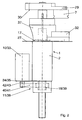
- the coffee machine machine 1 has a common housing 2, which can receive in its interior a non-illustrated water heater with a likewise not clarified hot water space.
- the housing 2 has a bore 3, in which a pipe section 4 is inserted sealingly, which forms an essential element of a brewing device 5.
- a brewing chamber 6 of the brewing device 5 is otherwise limited by an upper closure piece 7 and a lower closure piece 8.
- the upper closure piece 7 is usually formed as a water piston, ie from here the water is introduced during the brewing process in the brewing chamber 6 and sent through the coffee powder.
- the lower closure piece 8 is usually designed as a coffee piston, ie it serves as a carrier for the tablet of coffee powder.
- closure pieces 7 and 8 can also be used or driven in the reverse manner.
- the lower closure piece 8 always remains in the pipe section 4 and is only moved axially in a stroke-like manner along the vertical axis 9.
- the upper closure piece 7, however, is extended from the pipe section 4 in the direction of the axis 9 and then pivoted laterally, so that the then free opening of the pipe section 4 and the brewing chamber 6 can be freely charged with coffee powder.
- the two closure pieces 7 and 8 are piston-like and provided with seals that are not shown for clarity.
- the lower closure piece 8 is provided with a sieve for the passage of the coffee beverage and provided with the outlet for the coffee beverage to be dispensed in a known manner.
- a single first motor 10 is provided, which is arranged above the lower end of the housing 2.
- the engine 10 is followed by a transmission gear 11 (Fig. 2).
- Part of the transmission gear 11 is a nut / spindle unit whose spindle 12 is provided with a vertical axis 13.
- the axis 13 extends parallel to the axis 9 at a corresponding distance.
- the not shown in Fig. 1 and in Fig. 2 indicated, belonging to the spindle 12 nut 18 is rotatable but axially fixed, so that upon rotation of the nut 18, the spindle 12 a pure lifting movement in the direction of the axis 13 in accordance Double arrow 14 executes.
- the spindle 12 is rotatably connected to a pivot column 15 of a transfer case 16.
- the transfer case 16 also passes through the housing 2 of the coffee machine 1.
- Figures 1 and 3 show how the housing 2 extends laterally so that on the one hand the brewing device 5 and on the other hand, the transfer case 16 is received.
- the transfer case 16 has the pivot column 15 as an essential element.
- the pivot column 15 is mounted in a bore 19 in the housing 2. In the bore 19 engages a sliding block 28, which is screwed radially from the outside inwards into the housing 2 and thus cooperates with the pivoting column 15.
- a guide ring 17 is rotatably mounted in the housing 2.
- the guide ring 17 has a non-circular connection 20 (FIG. 4) with a flattening 21 which extends over the axial stroke of the pivoting column 15 and is associated with a counter-projection on the guide bush 17.
- a cover plate 27 thus prevents the guide ring 17th on an axial movement according to double arrow 14, but on the other hand allows a relative pivoting according to double arrow 22 about the axis 13th
- a slide 23 is provided, which is clearly visible in Fig. 1.
- the slideway 23 has an axis-parallel beginning region 24 at its lower end, to which a thread-like rising region 25 adjoins with a corresponding transition.
- the slide track 23 may in turn have an axis-parallel region 26. Since the pivot pillar 15 constitutes a mountable shaft part, a complicated shape of the slideway 23 can be easily made.
- the already mentioned sliding block 28 works together, which is fixedly arranged on the housing 2 and extends radially from the outside inwards into the slide 23.
- the pivot column 15 thus not only passes through the housing 2 in the vertical direction, but extends upward beyond this.
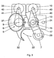
- a rotary arm 29 (Fig. 1 to 3) rotatably connected, at one free end of the upper closure piece 7 of the brewing device 5 is fixedly mounted.
- the rotary arm 29 has on its side facing away from the upper closure piece 7 a stop 30 which cooperates with a counter-stop 31 on the housing 2.
- the counter-stop 31 may be formed in the form of an adjustable screw to set the brewing position of the upper closure piece 7 and to form a support for the upper closure piece 7 in the brewing position.
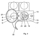
- the guide ring 17 is both a Schwenkabstreifer 32 as well as a hopper 37 rotatably connected, which thus as well as the guide ring 17 perform a pure rotational or pivotal movement about the axis 13 according to double arrow 22.
- the funnel 37 reaches a position above the brewing chamber 6 or the axis 9, so that in a further brewing cycle coffee powder can pass from a mill via a chute and the funnel 37 into the brewing chamber 6.
- the upper closure piece 7 is above a stationary arranged funnel, so that the upper closure piece 7 can be cleaned by a shower with hot water.
- the upper closure piece 7 In this parking position, the upper closure piece 7 on the one hand pivoted away from the axis 9 of the pipe section 4 according to double arrow 22. On the other hand, it is raised in the axial direction to provide, for example, below the closure piece 7 in the parking position under the closure piece 7 a drain funnel and a drain line for rinse water to perform a shower and cleaning process for the upper closure piece 7 in this parking position.
- the parking position is also the position in which the upper closure piece 7 is between two brewing cycles, ie each brewing cycle begins and ends in the parking position.
- a drive which takes place as a pure lifting or vertical drive according to double arrow 14 in the axis 9.
- the vertical drive has a further motor 33, which is like the motor 10 for the upper closure piece 7 above the housing 2 and independent of the first motor 10, for example, each arranged on a separate bearing plate 34 and 35 respectively.
- the motors 10 and 33 may be designed in particular as electric motors, as hydraulic motors or the like. It is possible to make the motors 10 and 33 coincident.
- the motor 33 a transmission 38 is connected downstream.
- a spindle 36 is driven according to arrow 14 purely axially in the axis 9.
- the lower closure piece 8 is arranged at the upper end of the spindle 36.
- the lower closure piece 8 is shown in Fig. 1 in its lower end position. It is retracted to reach the brewing position further up in the brewing chamber 6. In the course of a brewing cycle, the lower closure piece 8 can finally be moved so far upwards in the pipe section 4 that its upper surface is aligned with the outer termination plane of the housing 2 on the upper side.
- Fig. 1 reveals the particularly simple construction of the transfer case 16.
- the transfer case 16 includes the mounted in the bore 19 pivot column 15 with the slide 23, the stationary sliding block 28.
- the pivot column 15 further has the continuous flattening 21 for the entrainment of the guide ring 17.
- FIGS. 1 to 4 the design and arrangement of the drives can be seen.
- Fig. 1 illustrates that the two motors 10, 33 above the nuts 18, 39 of the transmission gear 11, 38 are arranged.
- the pinions 42, 43 on the shafts of the motors 10, 33 point downwards and are each connected via a toothed belt 40, 41 with the nuts 18, 39 in connection. Since the training on both drives coincide, double reference numerals are used in Fig. 2 respectively.
- the axes of the motors 10, 33 are perpendicular and parallel and spaced from the axes 9 and 13. In case of failure of the seal of the lower closure piece 8 escaping coffee and coffee powder can pass through the transmission gear 38 and drip down.
- the engine 33 is free of coffee and coffee powder, as well as the engine 10 and the transmission gear 11th
- a brewing cycle is as follows.
- the upper closure piece 7 is located in the parked position shown in dashed lines in FIG. 1 (see also FIG. 3).
- the lower closure piece 8 is in the lowest position shown in Fig. 1.
- the pipe section 4 of the brewing chamber 6 is thus open at the top.
- first coffee powder is freshly ground by a coffee grinder, not shown. It falls over a provided at the mill chute and the hopper 37 in the brewing chamber 6 and thus on the lower closure piece 8. Since the rotary arm 29 is swung away with the upper closure piece 7 in the park position over a comparatively large pivot angle (FIG.
- the motor 10 is set in motion in such a direction that the rotary arm 29 is pivoted with the upper closure piece 7 from the parking position to the standby position. This is done by a combined pivoting and lowering clockwise about the axis 13 according to double arrow 22 (FIG. 3), wherein the Schwenkabstreifer 32 are pivoted away with the hopper 37.
- the motor 10 remains in action beyond the standby position, ie, the standby position is traversed without interrupting the movement of the motor 10.
- the sliding block 28 comes into the axially parallel beginning region 24 of the slide track 23 via the transition region, so that the upper closure piece 7 is retracted with its seal into the tube section 4 from the readiness position into the brewing position in a purely axial lowering movement.
- the brewing position for the upper closure piece 7 is achieved, as shown in FIG. 1 reveals.
- the stop 30 lays on the counter-stop 31. The brewing position is reached.
- the motor 33 of the vertical drive for the lower closure piece 8 is set in action, and there is a lifting of the lower closure piece 8, which goes so far up that the coffee powder is compressed in the brewing chamber 6 into a tablet.
- the lower closure piece 8 presses against the fixed upper closure piece 7.
- a relief process for the tablet can advantageously follow, ie the direction of rotation of the motor 33 is reversed. It is understood that the way the lower closure piece 8 moves back down again, is dimensioned correspondingly small.
- the actual brewing process can take place, ie the control unit opens a corresponding valve and starts a pump for hot water, so that the corresponding amount of hot water through the upper closure piece 7, the pressed tablet of coffee powder and through the lower closure piece 8 is pressed through, so that the finished coffee beverage is dispensed at the coffee spout in a cup or a jug or other container.
- the brewing process is completed, and the upper closure piece 7 can be returned from the brewing position in the ready position and further in the parking position.
- the motor 10 is set in its other direction in motion, whereby the sliding block 28 initially works again in the axis-parallel beginning portion 24 of the slide 23, so that the upper closure piece 7 from the brewing position in the standby position axially upwards is raised.
- the ready position is traversed and the sliding block 28 enters the rising portion 25 of the slide 23, whereby on the one hand, the pivoting of the rotary arm 29 with the upper closure piece 7 from the standby position is enabled in the park position.
- the Schwenkabstreifer 32 which is connected to the guide ring 17, also in the clockwise direction (Fig. 3) is pivoted, which pivots over the surface of the housing 2.
- the motor 33 for the lower closure piece 8 was set in operation and lifted by an axial lifting operation in the pipe section 4, the leached tablet of coffee powder so far above the surface of the housing 1, that this tablet from the Schwenkabstreifer 32nd detected during the return movement of the rotary arm 29 and is dropped laterally into a receptacle for leached coffee powder tablets.
- the motor 33 is again driven in the reverse direction to reach the lower position shown in FIG.
- the upper closure piece 7 reaches the parking position above the outlet funnel and the shower cleaning process can take place.
- the hopper 37 is above the brewing chamber 6 and directs freshly ground coffee powder into the brewing chamber at the beginning of another brewing cycle.
Landscapes
- Engineering & Computer Science (AREA)
- Food Science & Technology (AREA)
- Mechanical Engineering (AREA)
- Apparatus For Making Beverages (AREA)
- Beverage Vending Machines With Cups, And Gas Or Electricity Vending Machines (AREA)
- Tea And Coffee (AREA)
Claims (10)
- Machine à café automatique, en particulier pour des tasses individuelles et une petite cafetière, avec un boîtier (1), avec au moins un dispositif d'admission de la mouture de café, avec un dispositif d'infusion (5) qui comporte une chambre d'infusion (6) formée par une partie tubulaire (4) stationnaire avec un axe vertical (9), ainsi que par deux obturateurs (7, 8), avec un système d'entraînement combiné à mouvement axial et pivotement avec un moteur (10), un engrenage (11) monté en aval et une colonne pivotante (15) mobile dans le sens axial et rotative pour déplacer l'obturateur supérieur (7), agencé de manière fixe sur un bras rotatif (29), dans une position d'infusion à l'intérieur de la partie tubulaire (4) et hors de celle-ci, pour déplacer l'obturateur supérieur (7) dans une position de repos hors de l'axe (9) de la partie tubulaire (4) et dans une position d'attente dans l'axe (9) de la partie tubulaire (4), avec un système d'entraînement vertical pour l'obturateur inférieur (8), comportant un autre moteur (33), un autre engrenage (38) monté en aval et une broche (36) mobile dans le sens axial, et avec une raclette pivotante (32) actionnée pour l'évacuation de la tablette de mouture de café, caractérisée en ce que la colonne pivotante (15) du système d'entraînement combiné à mouvement axial et pivotement du bras rotatif (29) avec l'obturateur supérieur (7) comporte une voie de glissement (23) avec une zone initiale (24) parallèle à l'axe, pour déplacer l'obturateur supérieur (7) hors de la position d'infusion dans la position d'attente, et une zone (25) à pente hélicoïdale pour le pivotement du bras rotatif (29) avec l'obturateur supérieur (7) hors de la position d'attente dans la position de repos, et en ce qu'il est prévu un coulisseau (28), fixe sur le boîtier (2) et entrant en prise avec la voie de glissement (23).
- Machine à café automatique selon la revendication 1, caractérisée en ce que pour le système d'entraînement combiné à mouvement axial et pivotement du bras rotatif (29) avec l'obturateur supérieur (7), ainsi que pour la raclette pivotante (32) actionnée, il est prévu un premier moteur (10), dont l'axe est, en particulier au-dessus d'une première transmission (11), parallèle et écarté de l'axe (13) du bras rotatif (29), indépendamment du système d'entraînement vertical pour l'obturateur inférieur (8).
- Machine à café automatique selon la revendication 1 ou 2, caractérisée en ce que, pour le système d'entraînement vertical de l'obturateur inférieur (8), il est prévu un deuxième moteur (33) indépendant du premier moteur (10), en particulier avec son axe au-dessus d'une deuxième transmission (38), parallèle et écarté de l'axe (9) de la chambre d'infusion (6).
- Machine à café automatique selon au moins l'une des revendications 1 à 3, caractérisée en ce que la transmission (11, 38), montée en aval du premier moteur (10) et/ou du deuxième moteur (33), comporte une courroie dentée, une courroie trapézoïdale ou un étage à roue dentée.
- Machine à café automatique selon l'une quelconque des revendications 1 à 4, caractérisée en ce que dans la partie supérieure de la colonne pivotante (15) est montée une bague de guidage (17) rotative, mais immobile dans le sens axial, laquelle est couplée à la colonne pivotante (15) de manière immobile en rotation, mais mobile dans le sens axial, et en ce que la raclette pivotante (32) pour l'évacuation de la tablette de mouture de café et/ou un entonnoir (37) pour introduire la mouture de café dans la chambre d'infusion (6) sont assemblés de manière solidaire en rotation avec la bague de guidage (17).
- Machine à café automatique selon la revendication 5, caractérisée en ce qu'il est prévu une liason non circulaire (20) entre la colonne pivotante (15) et la bague de guidage (17).
- Machine à café automatique selon la revendication 6, caractérisée en ce que l'assemblage excentrique (20) est formé par un méplat (21) continu dans le sens axial sur la colonne pivotante (15) et une saillie complémentaire sur la bague de guidage (17).
- Machine à café automatique selon l'une quelconque des revendications 1 à 7, caractérisée en ce que le bras rotatif (29) est prolongé au-delà de la colonne pivotante (15), sur le côté détourné de l'obturateur supérieur (7), et comporte une butée (30), en ce que sur le boîtier (2) est prévue une contre-butée (31), qui est associée à la butée (30) et sur laquelle prend appui la butée (30) du bras rotatif (29) dans la position d'infusion de l'obturateur supérieur (7).
- Machine à café automatique selon la revendication 2 ou 3, caractérisée en ce que le premier et le deuxième moteur (10, 33) pour l'entraînement de la colonne pivotante (15) et de l'obturateur inférieur (8) sont des moteurs électriques, en particulier des moteurs à courant continu.
- Machine à café automatique selon l'une quelconque des revendications 1 à 9, caractérisée en ce que la voie de glissement (23) dans la colonne pivotante (15) comporte une partie finale (26) parallèle à l'axe.
Applications Claiming Priority (2)
| Application Number | Priority Date | Filing Date | Title |
|---|---|---|---|
| DE102004023964 | 2004-05-14 | ||
| DE102004023964A DE102004023964B3 (de) | 2004-05-14 | 2004-05-14 | Kaffeemaschinenautomat |
Publications (2)
| Publication Number | Publication Date |
|---|---|
| EP1595480A1 EP1595480A1 (fr) | 2005-11-16 |
| EP1595480B1 true EP1595480B1 (fr) | 2007-10-03 |
Family
ID=34936156
Family Applications (1)
| Application Number | Title | Priority Date | Filing Date |
|---|---|---|---|
| EP05009804A Active EP1595480B1 (fr) | 2004-05-14 | 2005-05-04 | Machine à café automatique |
Country Status (14)
| Country | Link |
|---|---|
| US (1) | US7066079B2 (fr) |
| EP (1) | EP1595480B1 (fr) |
| JP (1) | JP2007536960A (fr) |
| KR (1) | KR101217130B1 (fr) |
| CN (1) | CN100479716C (fr) |
| AT (1) | ATE374556T1 (fr) |
| AU (1) | AU2005245270B2 (fr) |
| CA (1) | CA2566064C (fr) |
| DE (2) | DE102004023964B3 (fr) |
| HK (1) | HK1102743A1 (fr) |
| NZ (1) | NZ551791A (fr) |
| RU (1) | RU2362473C2 (fr) |
| WO (1) | WO2005112716A1 (fr) |
| ZA (1) | ZA200609022B (fr) |
Families Citing this family (14)
| Publication number | Priority date | Publication date | Assignee | Title |
|---|---|---|---|---|
| WO2007027206A2 (fr) * | 2005-04-11 | 2007-03-08 | Coffee Equipment Company | Machine pour infuser une boisson comme du café et procédé s'y rapportant |
| EP1940268B1 (fr) * | 2005-04-11 | 2011-11-09 | Starbucks Corporation | Machine destinee a l'infusion de boissons telles que le cafe et procede associe |
| EP2262402B1 (fr) * | 2008-03-24 | 2015-11-25 | Bunn-O-Matic Corporation | Système brasseur doté d'un mécanisme de brassage actif et compression par piston de réservoir tampon de substance de brasserie |
| ITTO20080311A1 (it) * | 2008-04-22 | 2009-10-23 | Lavazza Luigi Spa | Macchina per la preparazione di bevande |
| ITTO20080375A1 (it) * | 2008-05-20 | 2009-11-21 | Sgl Italia Srl | Macchina automatica per la preparazione di bevande |
| US9060645B2 (en) * | 2010-02-02 | 2015-06-23 | Uniterra, Inc. | Beverage brewing device and method |
| US8623441B2 (en) * | 2010-03-01 | 2014-01-07 | Concordia Coffee Company, Inc. | Method and apparatus for controlling brewed beverage quality |
| RU2012141643A (ru) * | 2010-03-01 | 2014-04-10 | Конкордиа Коффи Компани, Инк. | Устройство ускоренного заваривания при низком давлении |
| US9271599B2 (en) | 2010-03-19 | 2016-03-01 | N & W Global Vending S.P.A. | Infusion assembly |
| CN103750751B (zh) * | 2013-12-23 | 2015-11-04 | 深圳市中谷联创信息服务有限公司 | 一种用于冲制五谷杂粮粉粒的胶囊机 |
| ITUB20160854A1 (it) * | 2016-02-19 | 2016-05-19 | Sandenvendo Europe S P A | Dispositivo di erogazione di sostanza liquida per preparare bevande. |
| DE102019119103A1 (de) | 2019-07-15 | 2021-01-21 | Melitta Professional Coffee Solutions GmbH & Co. KG | Brüheinheit einer Kaffeemaschine |
| CN110974037B (zh) * | 2019-12-26 | 2021-12-28 | 珠海优特智厨科技有限公司 | 一种调料投放的检测方法及装置、存储介质、计算机设备 |
| DE102022126763A1 (de) | 2022-10-13 | 2024-04-18 | Melitta Professional Coffee Solutions GmbH & Co. KG | Brüheinheit einer Kaffeemaschine |
Family Cites Families (10)
| Publication number | Priority date | Publication date | Assignee | Title |
|---|---|---|---|---|
| CH404126A (it) * | 1962-09-01 | 1965-12-15 | Organizzazione Novi S R L | Macchina automatica per la produzione di caffè espresso |
| CH641030A5 (de) * | 1980-10-03 | 1984-02-15 | Rost Kurt | Verfahren zur herstellung von kaffee und kaffeemaschine zur ausfuehrung desselben. |
| EP0192797B1 (fr) * | 1985-03-01 | 1988-06-29 | Baumann, Jules (Jun.) | Machine à café |
| ES2011051B3 (es) * | 1986-02-26 | 1989-12-16 | Rolland Versini | Dispositivo para el filtrado automatico e instantaneo de liquidos alimentarios y aptos para ser suministrados por dosis correspondientes a una unidad de consumo o a un multiplo de esta unidad. |
| ATE100688T1 (de) * | 1990-04-04 | 1994-02-15 | Cma Spa | Automaten-gruppe fuer espresso-kaffee und verfahren zu deren betrieb. |
| IT221582Z2 (it) * | 1991-01-25 | 1994-07-22 | Ricerca Elettromeccanica Srl | Apparecchio per la produzione di caffe' |
| ES2054573B1 (es) * | 1991-05-13 | 1995-02-01 | Azkoyen Hosteleria | Mejoras introducidas en la patente de invencion n{ 9101161 por: "perfeccionamientos en maquinas automaticas expendedoras de infusiones de cafe. |
| DE4133697A1 (de) | 1991-10-11 | 1993-04-15 | Hgz Maschinenbau Ag | Kaffeemaschinenautomat |
| DE4329597C1 (de) * | 1993-09-02 | 1994-12-15 | Hgz Maschinenbau Ag | Kaffeemaschinenautomat |
| DE4333697A1 (de) | 1993-10-02 | 1995-04-06 | Merck Patent Gmbh | Verfahren zur Herstellung von 3-Aminopyridinen aus 3-Nitropyridinen |
-
2004
- 2004-05-14 DE DE102004023964A patent/DE102004023964B3/de not_active Expired - Fee Related
-
2005
- 2005-05-04 AT AT05009804T patent/ATE374556T1/de active
- 2005-05-04 EP EP05009804A patent/EP1595480B1/fr active Active
- 2005-05-04 DE DE502005001593T patent/DE502005001593D1/de active Active
- 2005-05-07 NZ NZ551791A patent/NZ551791A/en unknown
- 2005-05-07 JP JP2007512046A patent/JP2007536960A/ja active Pending
- 2005-05-07 WO PCT/EP2005/004966 patent/WO2005112716A1/fr active Application Filing
- 2005-05-07 CN CNB2005800152022A patent/CN100479716C/zh active Active
- 2005-05-07 CA CA2566064A patent/CA2566064C/fr active Active
- 2005-05-07 AU AU2005245270A patent/AU2005245270B2/en active Active
- 2005-05-07 RU RU2006144449/12A patent/RU2362473C2/ru active
- 2005-05-13 US US11/128,726 patent/US7066079B2/en active Active
-
2006
- 2006-10-30 ZA ZA2006/09022A patent/ZA200609022B/en unknown
- 2006-10-30 KR KR1020067022620A patent/KR101217130B1/ko active IP Right Grant
-
2007
- 2007-10-18 HK HK07111262.1A patent/HK1102743A1/xx unknown
Also Published As
| Publication number | Publication date |
|---|---|
| HK1102743A1 (en) | 2007-12-07 |
| KR101217130B1 (ko) | 2012-12-31 |
| EP1595480A1 (fr) | 2005-11-16 |
| JP2007536960A (ja) | 2007-12-20 |
| CA2566064C (fr) | 2012-08-28 |
| NZ551791A (en) | 2009-05-31 |
| ZA200609022B (en) | 2008-01-08 |
| WO2005112716A1 (fr) | 2005-12-01 |
| DE102004023964B3 (de) | 2006-01-19 |
| AU2005245270A1 (en) | 2005-12-01 |
| RU2006144449A (ru) | 2008-06-20 |
| ATE374556T1 (de) | 2007-10-15 |
| DE502005001593D1 (de) | 2007-11-15 |
| AU2005245270B2 (en) | 2009-08-06 |
| KR20070020019A (ko) | 2007-02-16 |
| US20050252383A1 (en) | 2005-11-17 |
| RU2362473C2 (ru) | 2009-07-27 |
| US7066079B2 (en) | 2006-06-27 |
| CN1953687A (zh) | 2007-04-25 |
| CA2566064A1 (fr) | 2005-12-01 |
| CN100479716C (zh) | 2009-04-22 |
Similar Documents
| Publication | Publication Date | Title |
|---|---|---|
| EP1595480B1 (fr) | Machine à café automatique | |
| EP0237475B1 (fr) | Ensemble piston-cylindre pour une machine à café et son procédé de fonctionnement | |
| EP0641536B1 (fr) | Machine à café automatique | |
| EP0969755B1 (fr) | Distributeur automatique de cafe | |
| EP1665968B1 (fr) | Tête d'infusion d'une machine espresso | |
| EP0245197B1 (fr) | Procédé pour préparer du café | |
| EP0937432B1 (fr) | Machine à café | |
| DE69309402T2 (de) | Vorrichtung und Verfahren zur Zubereitung von Getränken wie Kaffee, Suppe, Tee oder ähnlichen | |
| EP0931491B1 (fr) | Machine à café | |
| WO2009034002A1 (fr) | Dispositif d'infusion pour une machine à café | |
| EP2033550B1 (fr) | Unité d'infusion pour une machine à café | |
| DE4133697C2 (fr) | ||
| DE1805268A1 (de) | Aufbruehvorrichtung,insbesondere fuer Getraenkeautomaten | |
| DE2439417C3 (de) | Aufbrühvorrichtung für warme Getränke | |
| DE2006930A1 (de) | Maschine zur Zubereitung von Aufgußgetränken, insbesondere von Espresso-Kaffee | |
| EP2422663B1 (fr) | Groupe de distribution pour un automate de boissons | |
| EP2764802B1 (fr) | Machine à café entièrement automatique dotée d'une chambre à infusion pivotante et d'un déflecteur | |
| AT401338B (de) | Brüheinrichtung zur maschinellen kaffeebereitung | |
| DE202006004568U1 (de) | Vollautomatische Kaffeemaschine | |
| CH622695A5 (en) | Cleaning device for a beverage-making container | |
| DE8817074U1 (de) | Automatische Perkolatoreinheit für die schnelle Zubereitung von heißen Getränken, insbesondere von Kaffee, in variablen Mengen | |
| EP2698086B1 (fr) | Groupe de distribution | |
| EP2036467B1 (fr) | Percolateur destiné à la préparation de boissons chaudes | |
| CH681955A5 (fr) | ||
| DE9005650U1 (de) | Maschine zum Erzeugen von Kaffee-Aufguß |
Legal Events
| Date | Code | Title | Description |
|---|---|---|---|
| PUAI | Public reference made under article 153(3) epc to a published international application that has entered the european phase |
Free format text: ORIGINAL CODE: 0009012 |
|
| AK | Designated contracting states |
Kind code of ref document: A1 Designated state(s): AT BE BG CH CY CZ DE DK EE ES FI FR GB GR HU IE IS IT LI LT LU MC NL PL PT RO SE SI SK TR |
|
| AX | Request for extension of the european patent |
Extension state: AL BA HR LV MK YU |
|
| 17P | Request for examination filed |
Effective date: 20051119 |
|
| AKX | Designation fees paid |
Designated state(s): AT BE BG CH CY CZ DE DK EE ES FI FR GB GR HU IE IS IT LI LT LU MC NL PL PT RO SE SI SK TR |
|
| GRAP | Despatch of communication of intention to grant a patent |
Free format text: ORIGINAL CODE: EPIDOSNIGR1 |
|
| GRAS | Grant fee paid |
Free format text: ORIGINAL CODE: EPIDOSNIGR3 |
|
| GRAA | (expected) grant |
Free format text: ORIGINAL CODE: 0009210 |
|
| AK | Designated contracting states |
Kind code of ref document: B1 Designated state(s): AT BE BG CH CY CZ DE DK EE ES FI FR GB GR HU IE IS IT LI LT LU MC NL PL PT RO SE SI SK TR |
|
| REG | Reference to a national code |
Ref country code: GB Ref legal event code: FG4D Free format text: NOT ENGLISH |
|
| GBT | Gb: translation of ep patent filed (gb section 77(6)(a)/1977) |
Effective date: 20071003 |
|
| REG | Reference to a national code |
Ref country code: CH Ref legal event code: NV Representative=s name: RIEDERER HASLER & PARTNER PATENTANWAELTE AG Ref country code: CH Ref legal event code: EP |
|
| REG | Reference to a national code |
Ref country code: IE Ref legal event code: FG4D Free format text: LANGUAGE OF EP DOCUMENT: GERMAN |
|
| REF | Corresponds to: |
Ref document number: 502005001593 Country of ref document: DE Date of ref document: 20071115 Kind code of ref document: P |
|
| PG25 | Lapsed in a contracting state [announced via postgrant information from national office to epo] |
Ref country code: ES Free format text: LAPSE BECAUSE OF FAILURE TO SUBMIT A TRANSLATION OF THE DESCRIPTION OR TO PAY THE FEE WITHIN THE PRESCRIBED TIME-LIMIT Effective date: 20080114 Ref country code: SE Free format text: LAPSE BECAUSE OF FAILURE TO SUBMIT A TRANSLATION OF THE DESCRIPTION OR TO PAY THE FEE WITHIN THE PRESCRIBED TIME-LIMIT Effective date: 20080103 |
|
| PG25 | Lapsed in a contracting state [announced via postgrant information from national office to epo] |
Ref country code: IS Free format text: LAPSE BECAUSE OF FAILURE TO SUBMIT A TRANSLATION OF THE DESCRIPTION OR TO PAY THE FEE WITHIN THE PRESCRIBED TIME-LIMIT Effective date: 20080203 Ref country code: LT Free format text: LAPSE BECAUSE OF FAILURE TO SUBMIT A TRANSLATION OF THE DESCRIPTION OR TO PAY THE FEE WITHIN THE PRESCRIBED TIME-LIMIT Effective date: 20071003 Ref country code: PL Free format text: LAPSE BECAUSE OF FAILURE TO SUBMIT A TRANSLATION OF THE DESCRIPTION OR TO PAY THE FEE WITHIN THE PRESCRIBED TIME-LIMIT Effective date: 20071003 Ref country code: BG Free format text: LAPSE BECAUSE OF FAILURE TO SUBMIT A TRANSLATION OF THE DESCRIPTION OR TO PAY THE FEE WITHIN THE PRESCRIBED TIME-LIMIT Effective date: 20080103 Ref country code: PT Free format text: LAPSE BECAUSE OF FAILURE TO SUBMIT A TRANSLATION OF THE DESCRIPTION OR TO PAY THE FEE WITHIN THE PRESCRIBED TIME-LIMIT Effective date: 20080303 |
|
| ET | Fr: translation filed | ||
| PG25 | Lapsed in a contracting state [announced via postgrant information from national office to epo] |
Ref country code: DK Free format text: LAPSE BECAUSE OF FAILURE TO SUBMIT A TRANSLATION OF THE DESCRIPTION OR TO PAY THE FEE WITHIN THE PRESCRIBED TIME-LIMIT Effective date: 20071003 Ref country code: CZ Free format text: LAPSE BECAUSE OF FAILURE TO SUBMIT A TRANSLATION OF THE DESCRIPTION OR TO PAY THE FEE WITHIN THE PRESCRIBED TIME-LIMIT Effective date: 20071003 |
|
| PLBE | No opposition filed within time limit |
Free format text: ORIGINAL CODE: 0009261 |
|
| STAA | Information on the status of an ep patent application or granted ep patent |
Free format text: STATUS: NO OPPOSITION FILED WITHIN TIME LIMIT |
|
| PG25 | Lapsed in a contracting state [announced via postgrant information from national office to epo] |
Ref country code: RO Free format text: LAPSE BECAUSE OF FAILURE TO SUBMIT A TRANSLATION OF THE DESCRIPTION OR TO PAY THE FEE WITHIN THE PRESCRIBED TIME-LIMIT Effective date: 20071003 Ref country code: SK Free format text: LAPSE BECAUSE OF FAILURE TO SUBMIT A TRANSLATION OF THE DESCRIPTION OR TO PAY THE FEE WITHIN THE PRESCRIBED TIME-LIMIT Effective date: 20071003 |
|
| 26N | No opposition filed |
Effective date: 20080704 |
|
| PG25 | Lapsed in a contracting state [announced via postgrant information from national office to epo] |
Ref country code: GR Free format text: LAPSE BECAUSE OF FAILURE TO SUBMIT A TRANSLATION OF THE DESCRIPTION OR TO PAY THE FEE WITHIN THE PRESCRIBED TIME-LIMIT Effective date: 20080104 Ref country code: EE Free format text: LAPSE BECAUSE OF FAILURE TO SUBMIT A TRANSLATION OF THE DESCRIPTION OR TO PAY THE FEE WITHIN THE PRESCRIBED TIME-LIMIT Effective date: 20071003 |
|
| PG25 | Lapsed in a contracting state [announced via postgrant information from national office to epo] |
Ref country code: SI Free format text: LAPSE BECAUSE OF FAILURE TO SUBMIT A TRANSLATION OF THE DESCRIPTION OR TO PAY THE FEE WITHIN THE PRESCRIBED TIME-LIMIT Effective date: 20071003 |
|
| PG25 | Lapsed in a contracting state [announced via postgrant information from national office to epo] |
Ref country code: CY Free format text: LAPSE BECAUSE OF FAILURE TO SUBMIT A TRANSLATION OF THE DESCRIPTION OR TO PAY THE FEE WITHIN THE PRESCRIBED TIME-LIMIT Effective date: 20071003 |
|
| PG25 | Lapsed in a contracting state [announced via postgrant information from national office to epo] |
Ref country code: FI Free format text: LAPSE BECAUSE OF FAILURE TO SUBMIT A TRANSLATION OF THE DESCRIPTION OR TO PAY THE FEE WITHIN THE PRESCRIBED TIME-LIMIT Effective date: 20071003 |
|
| PG25 | Lapsed in a contracting state [announced via postgrant information from national office to epo] |
Ref country code: HU Free format text: LAPSE BECAUSE OF FAILURE TO SUBMIT A TRANSLATION OF THE DESCRIPTION OR TO PAY THE FEE WITHIN THE PRESCRIBED TIME-LIMIT Effective date: 20080404 |
|
| PG25 | Lapsed in a contracting state [announced via postgrant information from national office to epo] |
Ref country code: TR Free format text: LAPSE BECAUSE OF FAILURE TO SUBMIT A TRANSLATION OF THE DESCRIPTION OR TO PAY THE FEE WITHIN THE PRESCRIBED TIME-LIMIT Effective date: 20071003 |
|
| PG25 | Lapsed in a contracting state [announced via postgrant information from national office to epo] |
Ref country code: IT Free format text: LAPSE BECAUSE OF NON-PAYMENT OF DUE FEES Effective date: 20080531 |
|
| REG | Reference to a national code |
Ref country code: FR Ref legal event code: PLFP Year of fee payment: 12 |
|
| REG | Reference to a national code |
Ref country code: FR Ref legal event code: PLFP Year of fee payment: 13 |
|
| REG | Reference to a national code |
Ref country code: DE Ref legal event code: R082 Ref document number: 502005001593 Country of ref document: DE Representative=s name: REHBERG HUEPPE + PARTNER PATENTANWAELTE PARTG , DE Ref country code: DE Ref legal event code: R081 Ref document number: 502005001593 Country of ref document: DE Owner name: REX-ROYAL AG, DAELLIKON, CH Free format text: FORMER OWNER: HGZ MASCHINENBAU AG, DAELLIKON, ZUERICH, CH |
|
| REG | Reference to a national code |
Ref country code: CH Ref legal event code: PFA Owner name: REX-ROYAL AG, CH Free format text: FORMER OWNER: HGZ MASCHINENBAU AG, CH |
|
| REG | Reference to a national code |
Ref country code: LU Ref legal event code: HC Owner name: REX-ROYAL AG; CH Free format text: FORMER OWNER: HGZ MASCHINENBAU AG Effective date: 20170726 |
|
| REG | Reference to a national code |
Ref country code: NL Ref legal event code: HC Owner name: REX-ROYAL AG; CH Free format text: DETAILS ASSIGNMENT: CHANGE OF OWNER(S), CHANGE OF OWNER(S) NAME; FORMER OWNER NAME: HGZ MASCHINENBAU AG Effective date: 20170630 |
|
| REG | Reference to a national code |
Ref country code: FR Ref legal event code: CD Owner name: REX-ROYAL AG Effective date: 20171120 |
|
| REG | Reference to a national code |
Ref country code: BE Ref legal event code: HC Owner name: REX-ROYAL AG; CH Free format text: DETAILS ASSIGNMENT: CHANGE OF OWNER(S), CHANGEMENT NOM PROPRIETAIRE; FORMER OWNER NAME: HGZ MASCHINENBAU AG Effective date: 20170831 |
|
| REG | Reference to a national code |
Ref country code: AT Ref legal event code: HC Ref document number: 374556 Country of ref document: AT Kind code of ref document: T Owner name: REX-ROYAL AG, CH Effective date: 20180308 |
|
| REG | Reference to a national code |
Ref country code: FR Ref legal event code: PLFP Year of fee payment: 14 |
|
| PGFP | Annual fee paid to national office [announced via postgrant information from national office to epo] |
Ref country code: LU Payment date: 20240521 Year of fee payment: 20 |
|
| PGFP | Annual fee paid to national office [announced via postgrant information from national office to epo] |
Ref country code: NL Payment date: 20240522 Year of fee payment: 20 |
|
| PGFP | Annual fee paid to national office [announced via postgrant information from national office to epo] |
Ref country code: IE Payment date: 20240517 Year of fee payment: 20 |
|
| PGFP | Annual fee paid to national office [announced via postgrant information from national office to epo] |
Ref country code: GB Payment date: 20240522 Year of fee payment: 20 |
|
| PGFP | Annual fee paid to national office [announced via postgrant information from national office to epo] |
Ref country code: DE Payment date: 20240228 Year of fee payment: 20 |
|
| PGFP | Annual fee paid to national office [announced via postgrant information from national office to epo] |
Ref country code: MC Payment date: 20240521 Year of fee payment: 20 |
|
| PGFP | Annual fee paid to national office [announced via postgrant information from national office to epo] |
Ref country code: CH Payment date: 20240602 Year of fee payment: 20 |
|
| PGFP | Annual fee paid to national office [announced via postgrant information from national office to epo] |
Ref country code: AT Payment date: 20240517 Year of fee payment: 20 |
|
| PGFP | Annual fee paid to national office [announced via postgrant information from national office to epo] |
Ref country code: FR Payment date: 20240522 Year of fee payment: 20 |
|
| PGFP | Annual fee paid to national office [announced via postgrant information from national office to epo] |
Ref country code: BE Payment date: 20240521 Year of fee payment: 20 |