EP1595247B1 - Audio coding - Google Patents
Audio coding Download PDFInfo
- Publication number
- EP1595247B1 EP1595247B1 EP04709311A EP04709311A EP1595247B1 EP 1595247 B1 EP1595247 B1 EP 1595247B1 EP 04709311 A EP04709311 A EP 04709311A EP 04709311 A EP04709311 A EP 04709311A EP 1595247 B1 EP1595247 B1 EP 1595247B1
- Authority
- EP
- European Patent Office
- Prior art keywords
- signal
- encoded
- audio
- monaural
- phase
- Prior art date
- Legal status (The legal status is an assumption and is not a legal conclusion. Google has not performed a legal analysis and makes no representation as to the accuracy of the status listed.)
- Expired - Lifetime
Links
- 238000000034 method Methods 0.000 claims description 29
- 238000013139 quantization Methods 0.000 claims description 29
- 230000005236 sound signal Effects 0.000 claims description 24
- 230000005540 biological transmission Effects 0.000 claims description 8
- 238000005314 correlation function Methods 0.000 claims description 8
- 230000010363 phase shift Effects 0.000 claims description 5
- 230000001052 transient effect Effects 0.000 description 16
- 238000004458 analytical method Methods 0.000 description 9
- 230000008859 change Effects 0.000 description 9
- 238000012986 modification Methods 0.000 description 7
- 125000004122 cyclic group Chemical group 0.000 description 5
- 230000004048 modification Effects 0.000 description 5
- 230000035945 sensitivity Effects 0.000 description 5
- 230000008569 process Effects 0.000 description 3
- 230000009466 transformation Effects 0.000 description 3
- 230000003111 delayed effect Effects 0.000 description 2
- 238000010586 diagram Methods 0.000 description 2
- 238000001914 filtration Methods 0.000 description 2
- 238000012805 post-processing Methods 0.000 description 2
- 238000012545 processing Methods 0.000 description 2
- 238000005070 sampling Methods 0.000 description 2
- 238000001228 spectrum Methods 0.000 description 2
- 230000002194 synthesizing effect Effects 0.000 description 2
- 239000013598 vector Substances 0.000 description 2
- 241001123248 Arma Species 0.000 description 1
- 238000013459 approach Methods 0.000 description 1
- 230000008901 benefit Effects 0.000 description 1
- 230000015572 biosynthetic process Effects 0.000 description 1
- 238000004590 computer program Methods 0.000 description 1
- 238000011437 continuous method Methods 0.000 description 1
- 238000012937 correction Methods 0.000 description 1
- 230000001934 delay Effects 0.000 description 1
- 230000000694 effects Effects 0.000 description 1
- 238000000605 extraction Methods 0.000 description 1
- 230000004807 localization Effects 0.000 description 1
- 230000009467 reduction Effects 0.000 description 1
- 238000011160 research Methods 0.000 description 1
- 230000004044 response Effects 0.000 description 1
- 230000011218 segmentation Effects 0.000 description 1
- 238000000926 separation method Methods 0.000 description 1
- 239000007787 solid Substances 0.000 description 1
- 238000003786 synthesis reaction Methods 0.000 description 1
Images


Classifications
-
- G—PHYSICS
- G10—MUSICAL INSTRUMENTS; ACOUSTICS
- G10L—SPEECH ANALYSIS OR SYNTHESIS; SPEECH RECOGNITION; SPEECH OR VOICE PROCESSING; SPEECH OR AUDIO CODING OR DECODING
- G10L19/00—Speech or audio signals analysis-synthesis techniques for redundancy reduction, e.g. in vocoders; Coding or decoding of speech or audio signals, using source filter models or psychoacoustic analysis
- G10L19/008—Multichannel audio signal coding or decoding using interchannel correlation to reduce redundancy, e.g. joint-stereo, intensity-coding or matrixing
-
- H—ELECTRICITY
- H04—ELECTRIC COMMUNICATION TECHNIQUE
- H04S—STEREOPHONIC SYSTEMS
- H04S5/00—Pseudo-stereo systems, e.g. in which additional channel signals are derived from monophonic signals by means of phase shifting, time delay or reverberation
-
- H—ELECTRICITY
- H04—ELECTRIC COMMUNICATION TECHNIQUE
- H04S—STEREOPHONIC SYSTEMS
- H04S1/00—Two-channel systems
- H04S1/007—Two-channel systems in which the audio signals are in digital form
-
- H—ELECTRICITY
- H04—ELECTRIC COMMUNICATION TECHNIQUE
- H04S—STEREOPHONIC SYSTEMS
- H04S2420/00—Techniques used stereophonic systems covered by H04S but not provided for in its groups
- H04S2420/03—Application of parametric coding in stereophonic audio systems
Definitions
- the content carried by the two channels is predominantly monaural. Therefore, by exploiting inter-channel correlation and irrelevancy with techniques such as mid/side stereo coding and intensity coding bit rate savings can be made.
- Encoding methods to which this invention relates involve coding one of the channels fully, and coding a parametric description of how the other channel can be derived from the fully coded channel. Therefore, in the decoder, usually a single audio signal is available that has to be modified to obtain two different output channels.
- parameters used to describe the second channel may include interchannel time differences (ITDs), interchannel phase difference (IPD) and interchannel level differences (ILDs).
- EP-A-1107232 describes a method for encoding a stereo signal in which the encoded signal comprises information derived from one of a left channel or right channel input signal and parametric information which allows the other of the input signals to be recovered.
- WO-A-03/07656 discloses a method for encoding a stereo signal, in which a mono signal and stereo parameters are used to represent the stereo signal.
- the ITDs denote the difference in phase or time between the input channels. Therefore, the decoder can generate the non-encoded channel by taking the content of the encoded channel and creating the phase difference given by the ITDs. This process incorporates a certain degree of freedom. For example, only one output channel (say, the channel that is not encoded) may be modified with the prescribed phase difference. Alternatively, the encoded output channel could be modified with minus the prescribed phase difference. As a third example, one could apply half the prescribed phase difference to one channel and minus half the prescribed phase difference to the other channel. Since only the phase difference is prescribed, the offset (or distribution) in phase shift of both channels is not fixed.
- the mono signal component consists of a single sinusoid.
- the ITD parameter for this sinusoid increases linearly over time (i.e., over analysis frames).
- the IPD is just a linear transformation of the ITD.
- the IPD is only defined in the interval [- ⁇ : ⁇ ].
- Figure 1 shows the IPD as a function of time.
- the basic task of the decoder is to produce two output signals out of the single input signal. These output signals must satisfy the IPD parameter. This can be performed by copying the single input signal to the two output signals and modifying the phases of the output signals individually. Assuming a symmetrical distribution of the IPD across channels, this implies that the left output channel is modified by + IPD/2 , while the right output channel is phase-rotated by - IPD/2 . However, this approach leads to clearly audible artifacts caused by a phase jump that occurs at time t .
- phase change that is implied on the left and right output channels at a certain time instance t -, just before the occurrence of the phase jump, and t +, just after the phase jump.
- the phase-changes with respect to the mono input signal are shown as complex vectors (i.e., the angle between the output and input signal depicts the phase-change of each output channel).
- an aim of this invention is to preserve this information in the encoded signal without adding significantly to the size of the encoded signal.
- the invention provides an encoder and related items as set forth in the independent claims of this specification.
- the interchannel time difference (ITD), or phase difference (IPD) is estimated based on the relative time shift between the two input channels.
- the overall time shift (OTD), or overall phase shift (OPD) is determined by the best matching delay (or phase) between the fully-encoded monaural output signal and one of the input signals. Therefore, it is convenient to analyze the OTD (OPD) at the encoder level and add its value to the parameter bitstream.
- OTD OTD
- the OPD would have the behavior as shown in Fig. 3.
- the OPD basically describes the phase-change of the left channel across time, while the phase-change of the right channel is given by OPD(t) - IPD(t) . Since both parameters (OPD and IPD) are cyclic with a period of 2 ⁇ , the resulting phase changes of the independent output channels also become cyclic with a period of 2 ⁇ . Thus the resulting phase-changes of both output channels across time do not show phase discontinuities that were not present in the input signals.
- the OPD describes the phase change of the left channel, while the right channel is subsequently derived from the left channel using the IPD.
- Other linear combinations of these parameters can in principle be used for transmission.
- a trivial example would be to describe the phase-change of the right output channel with the OPD, and deriving the phase change of the left channel using the OPD and IPD.
- the crucial issue of this invention is to efficiently describe a pair of time-varying synthesis filters, in which the phase difference between the output channels is described with one (expensive) parameter, and an offset of the phase changes with another (much cheaper) parameter.
- a spatial parameter generating stage in an embodiment of the invention takes three signals as its input.
- a first two of these signals, designated L and R correspond to left and right channels of a stereo pair.
- Each of the channels is split up into multiple time-frequency tiles, for example, using a filterbank or frequency transform, as is conventional within this technical field.
- a further input to the encoder is a monaural signal S being the sum of the other signals L , R .
- This signal S is a monaural combination of the other signals L and R and has the same time-frequency separation as the other input signals.
- the output of the encoder is a bitstream containing the monaural audio signal S together with spatial parameters that are used by a decoder in decoding the bitstream.
- the encoder calculates the interchannel time difference (ITD) by determining the time lag between the L and R input signals.
- the overall time shift can be defined in two different ways: as a time difference between the sum signal S and the left input signal L , or as a time difference between the sum signal S and the right input signal R . It is convenient to measure the OTD relative to the stronger (i.e., higher energy) input signal, giving:
- the OTD values can subsequently be quantized and added to the bitstream. It has been found that a quantization error in the order of ⁇ /8 radians is acceptable. This is a relatively large quantization error compared to error that is acceptable for the ITD values.
- the spatial parameter bitstream contains an ILD, an ITD, an OTD and a correlation value for some or all frequency bands. Note that only for those frequency bands where an ITD value is transmitted is an OTD necessary.
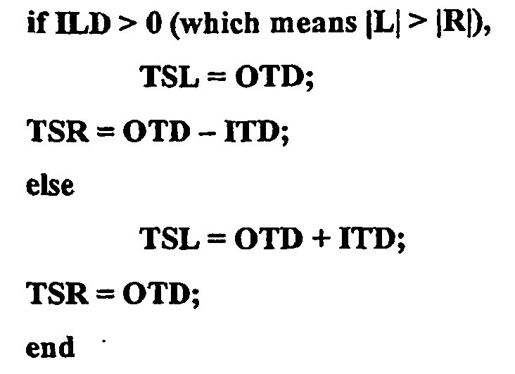
- the decoder determines the necessary phase-modification of the output channels based on the ITD, the OTD and the ILD, resulting in the time shift for the left channel (TSL) and for the right channel (TSR):
- a complete audio coder typically takes as an input two analogue time-varying audio frequency signals, digitizes these signals, generates a monaural sum signal and then generates an output bitstream comprising the coded monaural signal and the spatial parameters. (Alternatively, the input may be derived from two already digitized signals.) Those skilled in this technology will recognize that much of the following can be implemented readily using known techniques.
- the encoder 10 comprises respective transform modules 20 which split each incoming signal (L,R) into sub-band signals 16 (preferably with a bandwidth which increases with frequency).
- the modules 20 use time-windowing followed by a transform operation to perform time/frequency slicing, however, time-continuous methods could also be used (e.g., filterbanks).
- the ILD is determined by the level difference of the signals at a certain time instance for a given frequency band.
- One method to determine the ILD is to measure the rms value of the corresponding frequency band of both input channels and compute the ratio of these rms values (preferably expressed in dB).
- the ITDs are determined by the time or phase alignment which gives the best match between the waveforms of both channels.
- One method to obtain the ITD is to compute the cross-correlation function between two corresponding subband signals and searching for the maximum. The delay that corresponds to this maximum in the cross-correlation function can be used as ITD value.
- a second method is to compute the analytic signals of the left and right subband (i.e., computing phase and envelope values) and use the phase difference between the channels as IPD parameter.
- a complex filterbank e.g. an FFT
- a phase function can be derived over time.
- the correlation is obtained by first finding the ILD and ITD that gives the best match between the corresponding subband signals and subsequently measuring the similarity of the waveforms after compensation for the ITD and/or ILD.
- the correlation is defined as the similarity or dissimilarity of corresponding subband signals which can not be attributed to ILDs and/or ITDs.
- a suitable measure for this parameter is the coherence, which is the maximum value of the cross-correlation function across a set of delays.
- other measures could also be used, such as the relative energy of the difference signal after ILD and/or ITD compensation compared to the sum signal of corresponding subbands (preferably also compensated for ILDs and/or ITDs).
- This difference parameter is basically a linear transformation of the (maximum) correlation.
- JNDs just-noticeable differences
- the sensitivity to changes in the ITDs of human subjects can be characterized as having a constant phase threshold. This means that in terms of delay times, the quantization steps for the ITD should decrease with frequency. Alternatively, if the ITD is represented in the form of phase differences, the quantization steps should be independent of frequency. One method to implement this would be to take a fixed phase difference as quantization step and determine the corresponding time delay for each frequency band. This ITD value is then used as quantization step. In the preferred embodiment, ITD quantization steps are determined by a constant phase difference in each subband of 0.1 radians (rad). Thus, for each subband, the time difference that corresponds to 0.1 rad of the subband center frequency is used as quantization step.
- Another method would be to transmit phase differences which follow a frequency-independent quantization scheme. It is also known that above a certain frequency, the human auditory system is not sensitive to ITDs in the fine structure waveforms. This phenomenon can be exploited by only transmitting ITD parameters up to a certain frequency (typically 2 kHz).
- a third method of bitstream reduction is to incorporate ITD quantization steps that depend on the ILD and /or the correlation parameters of the same subband.
- the ITDs can be coded less accurately.
- the correlation it very low, it is known that the human sensitivity to changes in the ITD is reduced.
- larger ITD quantization errors may be applied if the correlation is small.
- An extreme example of this idea is to not transmit ITDs at all if the correlation is below a certain threshold.
- the quantization error of the correlation depends on (1) the correlation value itself and possibly (2) on the ILD. Correlation values near +1 are coded with a high accuracy (i.e., a small quantization step), while correlation values near 0 are coded with a low accuracy (a large quantization step).
- the absolute value of the (quantized) ILD of the current subband amounts 19 dB, no ITD and correlation values are transmitted for this subband. If the (quantized) correlation value of a certain subband amounts zero, no ITD value is transmitted for that subband.
- each frame requires a maximum of 233 bits to transmit the spatial parameters.
- a second possibility is to use quantization steps for the correlation that depend on the measured ILD of the same subband: for large ILDs (i.e., one channel is dominant in terms of energy), the quantization errors in the correlation become larger.
- An extreme example of this principle would be to not transmit correlation values for a certain subband at all if the absolute value of the IID for that subband is beyond a certain threshold.
- the analysis module 18 computes corresponding ILD, ITD and correlation (r).
- the ITD and correlation are computed simply by setting all FFT bins which belong to other groups to zero, multiplying the resulting (band-limited) FFTs from the left and right channels, followed by an inverse FFT transform.
- the resulting cross-correlation function is scanned for a peak within an interchannel delay between -64 and +63 samples.
- the internal delay corresponding to the peak is used as ITD value, and the value of the cross-correlation function at this peak is used as this subband's interaural correlation.
- the ILD is simply computed by taking the power ratio of the left and right channels for each subband.
- the analyzer 18 contains a sum signal generator 17.
- the sum signal generator generates a sum signal that is an average of the input signals.
- the additional processing may be carried out in generation of the sum signal, including, for example, phase correction.
- the sum signal can be converted to the time domain by (1) inserting complex conjugates at negative frequencies, (2) inverse FFT, (3) windowing, and (4) overlap-add.
- the signal can be encoded in a monaural layer 40 of a bitstream 50 in any number of conventional ways.
- a mp3 encoder can be used to generate the monaural layer 40 of the bitstream.
- an encoder detects rapid changes in an input signal, it can change the window length it employs for that particular time period so as to improve time and or frequency localization when encoding that portion of the input signal.
- a window switching flag is then embedded in the bitstream to indicate this switch to a decoder that later synthesizes the signal.
- a sinusoidal coder 30 of the type described in WO 01/69593-al is used to generate the monaural layer 40.
- the coder 30 comprises a transient coder 11, a sinusoidal coder 13 and a noise coder 15.
- the transient coder is an optional feature included in this embodiment.
- the coder 11 estimates if there is a transient signal component and its position (to sample accuracy) within the analysis window. If the position of a transient signal component is determined, the coder 11 tries to extract (the main part of) the transient signal component. It matches a shape function to a signal segment preferably starting at an estimated start position, and determines content underneath the shape function, by employing for example a (small) number of sinusoidal components and this information is contained in the transient code CT.
- the sum signal 12 less the transient component is furnished to the sinusoidal coder 13 where it is analyzed to determine the (deterministic) sinusoidal components.
- the sinusoidal coder encodes the input signal as tracks of sinusoidal components linked from one frame segment to the next.
- the tracks are initially represented by a start frequency, a start amplitude and a start phase for a sinusoid beginning in a given segment - a birth. Thereafter, the track is represented in subsequent segments by frequency differences, amplitude differences and, possibly, phase differences (continuations) until the segment in which the track ends (death) and this information is contained in the sinusoidal code CS.
- the signal less both the transient and sinusoidal components is assumed to mainly comprise noise and the noise analyzer 15 of the preferred embodiment produces a noise code CN representative of this noise.
- a spectrum of the noise is modeled by the noise coder with combined AR (auto-regressive) MA (moving average) filter parameters (pi,qi) according to an Equivalent Rectangular Bandwidth (ERB) scale.
- the filter parameters are fed to a noise synthesizer, which is mainly a filter, having a frequency response approximating the spectrum of the noise.
- the synthesizer generates reconstructed noise by filtering a white noise signal with the ARMA filtering parameters (pi,qi) and subsequently adds this to the synthesized transient and sinusoid signals to generate an estimate of the original sum signal.
- the multiplexer 41 produces the monaural audio layer 40 which is divided into frames 42 which represent overlapping time segments of length 16ms and which are updated every 8 ms, Figure 6.
- Each frame includes respective codes CT, CS and CN and in a decoder the codes for successive frames are blended in their overlap regions when synthesizing the monaural sum signal.
- each frame may only include up to one transient code CT and an example of such a transient is indicated by the numeral 44.
- the analyzer 18 further comprises a spatial parameter layer generator 19. This component performs the quantization of the spatial parameters for each spatial parameter frame as described above.
- the generator 19 divides each spatial layer channel 14 into frames 46, which represent overlapping time segments of length 64ms and which are updated every 32 ms, Figure 4.
- Each frame includes an ILD, an ITD, an OTD and a correlation value (r) and in the decoder the values for successive frames are blended in their overlap regions to determine the spatial layer parameters for any given time when synthesizing the signal.
- transient positions detected by the transient coder 11 in the monaural layer 40 are used by the generator 19 to determine if non-uniform time segmentation in the spatial parameter layer(s) 14 is required. If the encoder is using an mp3 coder to generate the monaural layer, then the presence of a window switching flag in the monaural stream is used by the generator as an estimate of a transient position.
- the monaural 40 and spatial representation 14 layers are in turn written by a multiplexer 43 to a bitstream 50.
- This audio stream 50 is in turn furnished to e.g. a data bus, an antenna system, a storage medium etc.
- a decoder 60 for use in combination with an encoder described above includes a de-multiplexer 62 which splits an incoming audio stream 50 into the monaural layer 40' and in this case a single spatial representation layer 14'.
- the monaural layer 40' is read by a conventional synthesizer 64 corresponding to the encoder which generated the layer to provide a time domain estimation of the original summed signal 12'.
- Spatial parameters 14' extracted by the de-multiplexer 62 are then applied by a post-processing module 66 to the sum signal 12' to generate left and right output signals.
- the post-processing module of the preferred embodiment also reads the monaural layer 14' information to locate the positions of transients in this signal and processes them appropriately. This is, of course, the case only where such transients have been encoded in the signal. (Alternatively, the synthesizer 64 could provide such an indication to the post-processor; however, this would require some slight modification of the otherwise conventional synthesizer 64.)
- a frequency-domain representation of the sum signal 12' as described in the analysis section is available for processing. This representation may be obtained by windowing and FFT operations of the time-domain waveform generated by the synthesizer 64. Then, the sum signal is copied to left and right output signal paths. Subsequently, the correlation between the left and right signals is modified with a decorrelator 69', 69" using the parameter r .
- each subband of the left signal is delayed by the value TSL and the right signal is delayed by TSR given the (quantized) from the values of OTD and ITD extracted from the bitstream corresponding to that subband.
- the values of TSL and TSR are calculated according to the formulae given above.
- the left and right subbands are scaled according to the ILD for that subband in respective stages 71', 7 1 ".
- Respective transform stages 72', 72" then convert the output signals to the time domain, by performing the following steps: (1) inserting complex conjugates at negative frequencies, (2) inverse FFT, (3) windowing, and (4) overlap-add.
- the parameters might include an ITD and a certain distribution key, e.g., x .
- the phase change of the left channel would be encoded as x ⁇ ITD, while the phase change of the right channel would be encoded as (1-x)*ITD.
- x a certain distribution key
- the phase change of the right channel would be encoded as (1-x)*ITD.
- many other encoding schemes can be used to implement embodiments of the invention.
- the present invention can be implemented in dedicated hardware, in software running on a DSP (Digital Signal Processor) or on a general-purpose computer.
- the present invention can be embodied in a tangible medium such as a CD-ROM or a DVD-ROM carrying a computer program for executing an encoding method according to the invention.
- the invention can also be embodied as a signal transmitted over a data network such as the Internet, or a signal transmitted by a broadcast service.
- the invention has particular application in the fields of Internet download, Internet radio, Solid State Audio (SSA), bandwidth extension schemes, for example, mp3PRO, CT-aacPlus (see www.codingtechnologies.com), and most audio coding schemes.
- SSA Solid State Audio
Abstract
Description
- Parametric descriptions of audio signals have gained interest during the last years, especially in the field of audio coding. It has been shown that transmitting (quantized) parameters that describe audio signals requires only little transmission capacity to re-synthesize a perceptually equal signal at the receiving end. In traditional waveform based audio coding schemes such as MPEG-LII, mp3 and AAC (MPEG-2 Advanced Audio Coding), stereo signals are encoded by encoding two monaural audio signals into one bitstream. This encodes each channel unambiguously, but at the expense of requiring double the data that would be required to encode a single channel.
- In many cases, the content carried by the two channels is predominantly monaural. Therefore, by exploiting inter-channel correlation and irrelevancy with techniques such as mid/side stereo coding and intensity coding bit rate savings can be made. Encoding methods to which this invention relates involve coding one of the channels fully, and coding a parametric description of how the other channel can be derived from the fully coded channel. Therefore, in the decoder, usually a single audio signal is available that has to be modified to obtain two different output channels.In particular, parameters used to describe the second channel may include interchannel time differences (ITDs), interchannel phase difference (IPD) and interchannel level differences (ILDs).
- EP-A-1107232 describes a method for encoding a stereo signal in which the encoded signal comprises information derived from one of a left channel or right channel input signal and parametric information which allows the other of the input signals to be recovered.
- WO-A-03/07656 discloses a method for encoding a stereo signal, in which a mono signal and stereo parameters are used to represent the stereo signal.
- In the parametric representations as described in the references mentioned above, the ITDs denote the difference in phase or time between the input channels. Therefore, the decoder can generate the non-encoded channel by taking the content of the encoded channel and creating the phase difference given by the ITDs. This process incorporates a certain degree of freedom. For example, only one output channel (say, the channel that is not encoded) may be modified with the prescribed phase difference. Alternatively, the encoded output channel could be modified with minus the prescribed phase difference. As a third example, one could apply half the prescribed phase difference to one channel and minus half the prescribed phase difference to the other channel. Since only the phase difference is prescribed, the offset (or distribution) in phase shift of both channels is not fixed. Although this is not a problem for the spatial quality of the decoded sound, it can result in audible artifacts. These artifacts occur because the overall phase shift is arbitrary. It may be that the phase modification of one or both of the output channels at any one encoding timeframe is not compatible with the phase modification of the previous frame. The present applicants have found that it is very difficult to correctly predict the correct overall phase shift in the decoder and have previously described a method to restrict phase modifications according to the phase modifications of the previous frame. This is a solution for the problem that works well, but it does not remove the cause of the problem.
- As described above, it has been shown to be very difficult to determine how the prescribed phase or time shift should be distributed over the two output channels at the decoder level. The following example explains this difficulty more clearly. Assume that in the decoder, the mono signal component consists of a single sinusoid. Furthermore, the ITD parameter for this sinusoid increases linearly over time (i.e., over analysis frames). In this example, we will focus on the IPD, keeping in mind that the IPD is just a linear transformation of the ITD. The IPD is only defined in the interval [-π : π]. Figure 1 shows the IPD as a function of time.
- Although at first sight this may seem a very theoretical example, such IPD behavior often occurs in audio recordings (for example if the frequency of the tones in the left and right channels differ by a few Hz). The basic task of the decoder is to produce two output signals out of the single input signal. These output signals must satisfy the IPD parameter. This can be performed by copying the single input signal to the two output signals and modifying the phases of the output signals individually. Assuming a symmetrical distribution of the IPD across channels, this implies that the left output channel is modified by +IPD/2, while the right output channel is phase-rotated by -IPD/2. However, this approach leads to clearly audible artifacts caused by a phase jump that occurs at time t. This can be understood with reference to Figure 2, in which is shown the phase change that is implied on the left and right output channels at a certain time instance t-, just before the occurrence of the phase jump, and t+, just after the phase jump. The phase-changes with respect to the mono input signal are shown as complex vectors (i.e., the angle between the output and input signal depicts the phase-change of each output channel).
- It will be seen that there is a large phase-inconsistency between the output signals just before and after the phase jump at time t: the vector of each output channel is rotated by almost π rad. If the subsequent frames of the outputs are combined by overlap-add, the overlapping parts of the output signals just before and after the phase jump cancel each other. This results in click-like artifacts in the output. These artifacts arise because the IPD parameter is cyclic with a period of 2π, but if the IPD is distributed across channels, the phase-change of each individual signal becomes cyclic with a period smaller than 2π (if the IPD is distributed symmetrically the phase change becomes cyclic with a period of π). The actual period of the phase change in each channel thus depends on the distribution method of IPD across channels, but it is smaller than 2π, giving rise to overlap-add problems in the decoder.
- Although the above example is a relatively simple case, we have found that for complex signals (with more frequency components within the same phase-modification frequency band, and with more complex behavior of the IPD parameter across time) it is very difficult to find the correct IPD distribution across output channels.
- At the encoder, information specifying how to distribute the IPD across channels is available. Therefore, an aim of this invention is to preserve this information in the encoded signal without adding significantly to the size of the encoded signal.
- To this end, the invention provides an encoder and related items as set forth in the independent claims of this specification.
- The interchannel time difference (ITD), or phase difference (IPD) is estimated based on the relative time shift between the two input channels. On the other hand, the overall time shift (OTD), or overall phase shift (OPD) is determined by the best matching delay (or phase) between the fully-encoded monaural output signal and one of the input signals. Therefore, it is convenient to analyze the OTD (OPD) at the encoder level and add its value to the parameter bitstream.
- An advantage of such a time-difference encoding is that the OTD (OPD) needs be encoded in only a very few bits since the auditory system is relatively insensitive to overall phase changes (although the binaural auditory system is very sensitive to ITD changes).
- For the problem addressed above, the OPD would have the behavior as shown in Fig. 3.
- Here, the OPD basically describes the phase-change of the left channel across time, while the phase-change of the right channel is given by OPD(t) - IPD(t). Since both parameters (OPD and IPD) are cyclic with a period of 2π, the resulting phase changes of the independent output channels also become cyclic with a period of 2π. Thus the resulting phase-changes of both output channels across time do not show phase discontinuities that were not present in the input signals.
- It should be noted that in this example, the OPD describes the phase change of the left channel, while the right channel is subsequently derived from the left channel using the IPD. Other linear combinations of these parameters can in principle be used for transmission. A trivial example would be to describe the phase-change of the right output channel with the OPD, and deriving the phase change of the left channel using the OPD and IPD. The crucial issue of this invention is to efficiently describe a pair of time-varying synthesis filters, in which the phase difference between the output channels is described with one (expensive) parameter, and an offset of the phase changes with another (much cheaper) parameter.
- Embodiments of the invention will now be described in detail, by way of example, and with reference to the accompanying drawings, in which:
- Figure 1 illustrates the effect of the IPD increasing linearly over time, and has already been discussed;
- Figure 2 illustrates the phase change of the output channels L and R with respect to the input channel just before (t-, left panel) and just after (t+, right panel) the phase jump in the IPD parameter, and has already been discussed;
- Figure 3 illustrates the OPD parameter for the case of a linearly increasing IPD, and has already been discussed;
- Figure 4 is a hardware block diagram of an encoder embodying of the invention; and
- Figure 5 is a hardware block diagram of a decoder embodying of the invention; and
- Figure 6 shows transient positions encoded in respective sub-frames of a monaural signal and the corresponding frames of a multi-channel layer.
- A spatial parameter generating stage in an embodiment of the invention takes three signals as its input. A first two of these signals, designated L and R, correspond to left and right channels of a stereo pair. Each of the channels is split up into multiple time-frequency tiles, for example, using a filterbank or frequency transform, as is conventional within this technical field. A further input to the encoder is a monaural signal S being the sum of the other signals L, R. This signal S is a monaural combination of the other signals L and R and has the same time-frequency separation as the other input signals. The output of the encoder is a bitstream containing the monaural audio signal S together with spatial parameters that are used by a decoder in decoding the bitstream.
- Then the encoder calculates the interchannel time difference (ITD) by determining the time lag between the L and R input signals. The time lag corresponds to the maximum in the cross-correlation function between corresponding time/frequency tiles of the input signals L(t, f) and R(t, f), such that:

- The overall time shift (OTD) can be defined in two different ways: as a time difference between the sum signal S and the left input signal L, or as a time difference between the sum signal S and the right input signal R. It is convenient to measure the OTD relative to the stronger (i.e., higher energy) input signal, giving:

- The OTD values can subsequently be quantized and added to the bitstream. It has been found that a quantization error in the order of π/8 radians is acceptable. This is a relatively large quantization error compared to error that is acceptable for the ITD values. Hence the spatial parameter bitstream contains an ILD, an ITD, an OTD and a correlation value for some or all frequency bands. Note that only for those frequency bands where an ITD value is transmitted is an OTD necessary.
- The decoder determines the necessary phase-modification of the output channels based on the ITD, the OTD and the ILD, resulting in the time shift for the left channel (TSL) and for the right channel (TSR):
- It will be understood that a complete audio coder typically takes as an input two analogue time-varying audio frequency signals, digitizes these signals, generates a monaural sum signal and then generates an output bitstream comprising the coded monaural signal and the spatial parameters. (Alternatively, the input may be derived from two already digitized signals.) Those skilled in this technology will recognize that much of the following can be implemented readily using known techniques.
- In general, the
encoder 10 comprisesrespective transform modules 20 which split each incoming signal (L,R) into sub-band signals 16 (preferably with a bandwidth which increases with frequency). In the preferred embodiment, themodules 20 use time-windowing followed by a transform operation to perform time/frequency slicing, however, time-continuous methods could also be used (e.g., filterbanks). - The next steps for determination of the
sum signal 12 and extraction of theparameters 14 are carried out within ananalysis module 18 and comprise: - finding the level difference (ILD) of corresponding sub-band signals 16,
- finding the time difference (ITD or IPD) of corresponding sub-band signals 16, and
- describing the amount of similarity or dissimilarity of the waveforms which cannot be accounted for by ILDs or ITDs.
- The ILD is determined by the level difference of the signals at a certain time instance for a given frequency band. One method to determine the ILD is to measure the rms value of the corresponding frequency band of both input channels and compute the ratio of these rms values (preferably expressed in dB).
- The ITDs are determined by the time or phase alignment which gives the best match between the waveforms of both channels. One method to obtain the ITD is to compute the cross-correlation function between two corresponding subband signals and searching for the maximum. The delay that corresponds to this maximum in the cross-correlation function can be used as ITD value.
- A second method is to compute the analytic signals of the left and right subband (i.e., computing phase and envelope values) and use the phase difference between the channels as IPD parameter. Here, a complex filterbank (e.g. an FFT) is used and by looking at a certain bin (frequency region) a phase function can be derived over time. By doing this for both left and right channel, the phase difference IPD (rather then cross-correlating two filtered signals) can be estimated.
- The correlation is obtained by first finding the ILD and ITD that gives the best match between the corresponding subband signals and subsequently measuring the similarity of the waveforms after compensation for the ITD and/or ILD. Thus, in this framework, the correlation is defined as the similarity or dissimilarity of corresponding subband signals which can not be attributed to ILDs and/or ITDs. A suitable measure for this parameter is the coherence, which is the maximum value of the cross-correlation function across a set of delays. However, other measures could also be used, such as the relative energy of the difference signal after ILD and/or ITD compensation compared to the sum signal of corresponding subbands (preferably also compensated for ILDs and/or ITDs). This difference parameter is basically a linear transformation of the (maximum) correlation.
- An important issue of transmission of parameters is the accuracy of the parameter representation (i.e., the size of quantization errors), which is directly related to the necessary transmission capacity and the audio quality. In this section, several issues with respect to the quantization of the spatial parameters will be discussed. The basic idea is to base the quantization errors on so-called just-noticeable differences (JNDs) of the spatial cues. To be more specific, the quantization error is determined by the sensitivity of the human auditory system to changes in the parameters. Since it is well known that the sensitivity to changes in the parameters strongly depends on the values of the parameters itself, the following methods are applied to determine the discrete quantization steps.
- It is known from psychoacoustic research that the sensitivity to changes in the IID depends on the ILD itself. If the ILD is expressed in dB, deviations of approximately 1 dB from a reference of 0 dB are detectable, while changes in the order of 3 dB are required if the reference level difference amounts 20 dB. Therefore, quantization errors can be larger if the signals of the left and right channels have a larger level difference. For example, this can be applied by first measuring the level difference between the channels, followed by a nonlinear (compressive) transformation of the obtained level difference and subsequently a linear quantization process, or by using a lookup table for the available ILD values which have a nonlinear distribution. In the preferred embodiment, ILDs (in dB) are quantized to the closest value out of the following set I:

- The sensitivity to changes in the ITDs of human subjects can be characterized as having a constant phase threshold. This means that in terms of delay times, the quantization steps for the ITD should decrease with frequency. Alternatively, if the ITD is represented in the form of phase differences, the quantization steps should be independent of frequency. One method to implement this would be to take a fixed phase difference as quantization step and determine the corresponding time delay for each frequency band. This ITD value is then used as quantization step. In the preferred embodiment, ITD quantization steps are determined by a constant phase difference in each subband of 0.1 radians (rad). Thus, for each subband, the time difference that corresponds to 0.1 rad of the subband center frequency is used as quantization step.
- Another method would be to transmit phase differences which follow a frequency-independent quantization scheme. It is also known that above a certain frequency, the human auditory system is not sensitive to ITDs in the fine structure waveforms. This phenomenon can be exploited by only transmitting ITD parameters up to a certain frequency (typically 2 kHz).
- A third method of bitstream reduction is to incorporate ITD quantization steps that depend on the ILD and /or the correlation parameters of the same subband. For large ILDs, the ITDs can be coded less accurately. Furthermore, if the correlation it very low, it is known that the human sensitivity to changes in the ITD is reduced. Hence larger ITD quantization errors may be applied if the correlation is small. An extreme example of this idea is to not transmit ITDs at all if the correlation is below a certain threshold.
- The quantization error of the correlation depends on (1) the correlation value itself and possibly (2) on the ILD. Correlation values near +1 are coded with a high accuracy (i.e., a small quantization step), while correlation values near 0 are coded with a low accuracy (a large quantization step). In the preferred embodiment, a set of non-linearly distributed correlation values (r) are quantized to the closest value of the following ensemble R:

- If the absolute value of the (quantized) ILD of the current subband amounts 19 dB, no ITD and correlation values are transmitted for this subband. If the (quantized) correlation value of a certain subband amounts zero, no ITD value is transmitted for that subband.
- In this way, each frame requires a maximum of 233 bits to transmit the spatial parameters. With an update framelength of 1024 samples and a sampling rate of 44.1 kHz, the maximum bitrate for transmission amounts less than 10.25 kbit/s [233‡44100/1024 = 10.034kbit/s]. (It should be noted that using entropy coding or differential coding, this bitrate can be reduced further.)
- A second possibility is to use quantization steps for the correlation that depend on the measured ILD of the same subband: for large ILDs (i.e., one channel is dominant in terms of energy), the quantization errors in the correlation become larger. An extreme example of this principle would be to not transmit correlation values for a certain subband at all if the absolute value of the IID for that subband is beyond a certain threshold.
- With reference to Figure 4, in more detail, in the
modules 20, the left and right incoming signals are split up in various time frames (2048 samples at 44.1 kHz sampling rate) and windowed with a square-root Hanning window. Subsequently, FFTs are computed. The negative FFT frequencies are discarded and the resulting FFTs are subdivided into groups orsubbands 16 of FFT bins. The number of FFT bins that are combined in a subband g depends on the frequency: at higher frequencies more bins are combined than at lower frequencies. In the current implementation, FFT bins corresponding to approximately 1.8 ERBs are grouped, resulting in 20 subbands to represent the entire audible frequency range. The resulting number of FFT bins S[g] of each subsequent subband (starting at the lowest frequency) is:
- Thus, the first three subbands contain 4 FFT bins, the fourth subband contains 5 FFT bins, etc. For each subband, the
analysis module 18 computes corresponding ILD, ITD and correlation (r). The ITD and correlation are computed simply by setting all FFT bins which belong to other groups to zero, multiplying the resulting (band-limited) FFTs from the left and right channels, followed by an inverse FFT transform. The resulting cross-correlation function is scanned for a peak within an interchannel delay between -64 and +63 samples. The internal delay corresponding to the peak is used as ITD value, and the value of the cross-correlation function at this peak is used as this subband's interaural correlation. Finally, the ILD is simply computed by taking the power ratio of the left and right channels for each subband. - The
analyzer 18 contains asum signal generator 17. The sum signal generator generates a sum signal that is an average of the input signals. (In other embodiments, the additional processing may be carried out in generation of the sum signal, including, for example, phase correction. If necessary, the sum signal can be converted to the time domain by (1) inserting complex conjugates at negative frequencies, (2) inverse FFT, (3) windowing, and (4) overlap-add. - Given the representation of the
sum signal 12 in the time and/or frequency domain as described above, the signal can be encoded in amonaural layer 40 of abitstream 50 in any number of conventional ways. For example, a mp3 encoder can be used to generate themonaural layer 40 of the bitstream. When such an encoder detects rapid changes in an input signal, it can change the window length it employs for that particular time period so as to improve time and or frequency localization when encoding that portion of the input signal. A window switching flag is then embedded in the bitstream to indicate this switch to a decoder that later synthesizes the signal. - In the preferred embodiment, however, a
sinusoidal coder 30 of the type described in WO 01/69593-al is used to generate themonaural layer 40. Thecoder 30 comprises atransient coder 11, asinusoidal coder 13 and anoise coder 15. The transient coder is an optional feature included in this embodiment. - When the
signal 12 enters thetransient coder 11, for each update interval, the coder estimates if there is a transient signal component and its position (to sample accuracy) within the analysis window. If the position of a transient signal component is determined, thecoder 11 tries to extract (the main part of) the transient signal component. It matches a shape function to a signal segment preferably starting at an estimated start position, and determines content underneath the shape function, by employing for example a (small) number of sinusoidal components and this information is contained in the transient code CT. - The
sum signal 12 less the transient component is furnished to thesinusoidal coder 13 where it is analyzed to determine the (deterministic) sinusoidal components. In brief, the sinusoidal coder encodes the input signal as tracks of sinusoidal components linked from one frame segment to the next. The tracks are initially represented by a start frequency, a start amplitude and a start phase for a sinusoid beginning in a given segment - a birth. Thereafter, the track is represented in subsequent segments by frequency differences, amplitude differences and, possibly, phase differences (continuations) until the segment in which the track ends (death) and this information is contained in the sinusoidal code CS. - The signal less both the transient and sinusoidal components is assumed to mainly comprise noise and the
noise analyzer 15 of the preferred embodiment produces a noise code CN representative of this noise. Conventionally, as in, for example, WO 01/89086-A1, a spectrum of the noise is modeled by the noise coder with combined AR (auto-regressive) MA (moving average) filter parameters (pi,qi) according to an Equivalent Rectangular Bandwidth (ERB) scale. Within a decoder, the filter parameters are fed to a noise synthesizer, which is mainly a filter, having a frequency response approximating the spectrum of the noise. The synthesizer generates reconstructed noise by filtering a white noise signal with the ARMA filtering parameters (pi,qi) and subsequently adds this to the synthesized transient and sinusoid signals to generate an estimate of the original sum signal. - The
multiplexer 41 produces themonaural audio layer 40 which is divided intoframes 42 which represent overlapping time segments of length 16ms and which are updated every 8 ms, Figure 6. Each frame includes respective codes CT, CS and CN and in a decoder the codes for successive frames are blended in their overlap regions when synthesizing the monaural sum signal. In the present embodiment, it is assumed that each frame may only include up to one transient code CT and an example of such a transient is indicated by the numeral 44. - The
analyzer 18 further comprises a spatialparameter layer generator 19. This component performs the quantization of the spatial parameters for each spatial parameter frame as described above. In general, thegenerator 19 divides eachspatial layer channel 14 intoframes 46, which represent overlapping time segments of length 64ms and which are updated every 32 ms, Figure 4. Each frame includes an ILD, an ITD, an OTD and a correlation value (r) and in the decoder the values for successive frames are blended in their overlap regions to determine the spatial layer parameters for any given time when synthesizing the signal. - In the preferred embodiment, transient positions detected by the
transient coder 11 in the monaural layer 40 (or by a corresponding analyzer module in the summed signal 12) are used by thegenerator 19 to determine if non-uniform time segmentation in the spatial parameter layer(s) 14 is required. If the encoder is using an mp3 coder to generate the monaural layer, then the presence of a window switching flag in the monaural stream is used by the generator as an estimate of a transient position. - Finally, once the monaural 40 and
spatial representation 14 layers have been generated, they are in turn written by amultiplexer 43 to abitstream 50. Thisaudio stream 50 is in turn furnished to e.g. a data bus, an antenna system, a storage medium etc. - Referring now to Figure 5, a
decoder 60 for use in combination with an encoder described above includes a de-multiplexer 62 which splits anincoming audio stream 50 into the monaural layer 40' and in this case a single spatial representation layer 14'. The monaural layer 40' is read by aconventional synthesizer 64 corresponding to the encoder which generated the layer to provide a time domain estimation of the original summed signal 12'. - Spatial parameters 14' extracted by the de-multiplexer 62 are then applied by a
post-processing module 66 to the sum signal 12' to generate left and right output signals. The post-processing module of the preferred embodiment also reads the monaural layer 14' information to locate the positions of transients in this signal and processes them appropriately. This is, of course, the case only where such transients have been encoded in the signal. (Alternatively, thesynthesizer 64 could provide such an indication to the post-processor; however, this would require some slight modification of the otherwiseconventional synthesizer 64.) - Within the post-processor 66, it is assumed that a frequency-domain representation of the sum signal 12' as described in the analysis section is available for processing. This representation may be obtained by windowing and FFT operations of the time-domain waveform generated by the
synthesizer 64. Then, the sum signal is copied to left and right output signal paths. Subsequently, the correlation between the left and right signals is modified with adecorrelator 69', 69" using the parameter r. - Subsequently, in
respective stages 70', 70", each subband of the left signal is delayed by the value TSL and the right signal is delayed by TSR given the (quantized) from the values of OTD and ITD extracted from the bitstream corresponding to that subband. The values of TSL and TSR are calculated according to the formulae given above. Finally, the left and right subbands are scaled according to the ILD for that subband in respective stages 71', 7 1 ". Respective transform stages 72', 72" then convert the output signals to the time domain, by performing the following steps: (1) inserting complex conjugates at negative frequencies, (2) inverse FFT, (3) windowing, and (4) overlap-add. - As an alternative to the above coding scheme, there are many other possible ways in which the phase difference could be encoded. For example, the parameters might include an ITD and a certain distribution key, e.g., x. Then, the phase change of the left channel would be encoded as x‡ITD, while the phase change of the right channel would be encoded as (1-x)*ITD. Clearly, many other encoding schemes can be used to implement embodiments of the invention.
- It is observed that the present invention can be implemented in dedicated hardware, in software running on a DSP (Digital Signal Processor) or on a general-purpose computer. The present invention can be embodied in a tangible medium such as a CD-ROM or a DVD-ROM carrying a computer program for executing an encoding method according to the invention. The invention can also be embodied as a signal transmitted over a data network such as the Internet, or a signal transmitted by a broadcast service. The invention has particular application in the fields of Internet download, Internet radio, Solid State Audio (SSA), bandwidth extension schemes, for example, mp3PRO, CT-aacPlus (see www.codingtechnologies.com), and most audio coding schemes.
Claims (16)
- A method of coding an audio signal, the method comprising:generating a monaural signal from at least two audio input channels;generating an encoded signal that includes the monaural signal and a set of parameters to enable reproduction of two audio output signals each corresponding to a respective input channel;characterized in that:the parameters include an indication of an overall shift, this being a measure of the delay between the encoded monaural output signal and one of the input signals.
- A method as claimed in claim 1, wherein, for transmission, a linear combination of the overall shift and an interchannel phase or time difference is used.
- A method according to claim 1 in which the overall shift is an overall time shift.
- A method according to claim 1 in which the overall shift is an overall phase shift.
- A method according to claim 1 in which the overall shift is determined by the best matching delay (or phase) between the fully-encoded monaural output signal and one of the input signals.
- A method according to claim 5 in which the best matching delay corresponds to the maximum in the cross-correlation function between corresponding time/frequency tiles of the input signals
- A method according to claim 1 in which the overall shift is calculated with respect to the input signal of greater amplitude.
- A method according to claim 1 in which the phase difference is encoded with a lesser quantization error than the overall shift.
- An encoder for coding an audio signal comprising
means for generating a monaural signal from at least two audio input channels;
means for generating an encoded signal that includes the monaural signal and parameters to enable reproduction of two audio output signals, each corresponding to a respective input channel;
characterized in that
the parameters include an indication of an overall shift, this being a measure of the delay between the encoded monaural output signal and one of the input signals. - An apparatus for supplying an audio signal, the apparatus comprising:an input for receiving an audio signal,an encoder according to claim 9 for encoding the audio signal to obtain an encoded audio signal, andan output for supplying the encoded audio signal.
- An encoded audio signal, the signal comprising
a monaural signal derived from at least two audio input channels;
an encoded signal that includes the monaural signal and parameters to enable reproduction of two audio output signals, each corresponding to a respective input channel;
characterized in that:the parameters include an indication of an overall shift, this being a measure of the delay between the encoded monaural output signal and one of the input signals. - An encoded audio signal as claimed in claim 11, wherein, for transmission, a linear combination of the overall shift and an interchannel phase or time difference is used.
- A method of decoding an encoded audio signal representing at least two audio channels, the encoded audio signal including an encoded monaural signal and spatial parameters,
characterized in that the encoded signal includes parameters indicative of an overall shift being a measure of the delay between the encoded monaural output signal and one of the audio channels;
and in that the method comprises generating a stereo pair of output audio signals offset in time and phase by an interval specified by the parameters. - A decoder for decoding an encoded audio signal representing at least two audio channels, the encoded audio signal including an encoded monaural signal and spatial parameters,
characterized in that the encoded audio signal includes parameters indicative of an overall shift being a measure of the delay between the encoded monaural signal and one of the audio channels;
and in that the decoder comprises means for generating a stereo pair of output audio signals offset in time and phase by an interval specified by the parameters. - A decoder as claimed in claim 14, wherein a linear combination of the overall shift and an interchannel time or phase difference is used for transmission.
- An apparatus for supplying a decoded audio signal, the apparatus comprising:an input for receiving an encoded audio signal,a decoder as claimed in claim 14 for decoding the encoded audio signal to obtain a multi-channel output signal,an output for supplying or reproducing the multi-channel output signal.
Priority Applications (1)
| Application Number | Priority Date | Filing Date | Title |
|---|---|---|---|
| EP04709311A EP1595247B1 (en) | 2003-02-11 | 2004-02-09 | Audio coding |
Applications Claiming Priority (4)
| Application Number | Priority Date | Filing Date | Title |
|---|---|---|---|
| EP03100278 | 2003-02-11 | ||
| EP03100278 | 2003-02-11 | ||
| EP04709311A EP1595247B1 (en) | 2003-02-11 | 2004-02-09 | Audio coding |
| PCT/IB2004/050085 WO2004072956A1 (en) | 2003-02-11 | 2004-02-09 | Audio coding |
Publications (2)
| Publication Number | Publication Date |
|---|---|
| EP1595247A1 EP1595247A1 (en) | 2005-11-16 |
| EP1595247B1 true EP1595247B1 (en) | 2006-09-13 |
Family
ID=32865026
Family Applications (1)
| Application Number | Title | Priority Date | Filing Date |
|---|---|---|---|
| EP04709311A Expired - Lifetime EP1595247B1 (en) | 2003-02-11 | 2004-02-09 | Audio coding |
Country Status (9)
| Country | Link |
|---|---|
| US (2) | US7181019B2 (en) |
| EP (1) | EP1595247B1 (en) |
| JP (1) | JP4431568B2 (en) |
| KR (1) | KR101049751B1 (en) |
| CN (1) | CN1748247B (en) |
| AT (1) | ATE339759T1 (en) |
| DE (1) | DE602004002390T2 (en) |
| ES (1) | ES2273216T3 (en) |
| WO (1) | WO2004072956A1 (en) |
Families Citing this family (102)
| Publication number | Priority date | Publication date | Assignee | Title |
|---|---|---|---|---|
| US7116787B2 (en) * | 2001-05-04 | 2006-10-03 | Agere Systems Inc. | Perceptual synthesis of auditory scenes |
| US7644003B2 (en) | 2001-05-04 | 2010-01-05 | Agere Systems Inc. | Cue-based audio coding/decoding |
| RU2325046C2 (en) * | 2002-07-16 | 2008-05-20 | Конинклейке Филипс Электроникс Н.В. | Audio coding |
| FR2852779B1 (en) * | 2003-03-20 | 2008-08-01 | PROCESS FOR PROCESSING AN ELECTRICAL SIGNAL OF SOUND | |
| BRPI0415951B1 (en) | 2003-10-30 | 2018-08-28 | Coding Tech Ab | audio method and encoder to encode an audio signal, and audio method and decoder to decode an encoded audio signal |
| US7805313B2 (en) | 2004-03-04 | 2010-09-28 | Agere Systems Inc. | Frequency-based coding of channels in parametric multi-channel coding systems |
| US7646875B2 (en) * | 2004-04-05 | 2010-01-12 | Koninklijke Philips Electronics N.V. | Stereo coding and decoding methods and apparatus thereof |
| US8843378B2 (en) * | 2004-06-30 | 2014-09-23 | Fraunhofer-Gesellschaft Zur Foerderung Der Angewandten Forschung E.V. | Multi-channel synthesizer and method for generating a multi-channel output signal |
| US7391870B2 (en) * | 2004-07-09 | 2008-06-24 | Fraunhofer-Gesellschaft Zur Foerderung Der Angewandten Forschung E V | Apparatus and method for generating a multi-channel output signal |
| ATE444549T1 (en) * | 2004-07-14 | 2009-10-15 | Koninkl Philips Electronics Nv | SOUND CHANNEL CONVERSION |
| DE102004042819A1 (en) | 2004-09-03 | 2006-03-23 | Fraunhofer-Gesellschaft zur Förderung der angewandten Forschung e.V. | Apparatus and method for generating a coded multi-channel signal and apparatus and method for decoding a coded multi-channel signal |
| JP4892184B2 (en) * | 2004-10-14 | 2012-03-07 | パナソニック株式会社 | Acoustic signal encoding apparatus and acoustic signal decoding apparatus |
| US8204261B2 (en) * | 2004-10-20 | 2012-06-19 | Fraunhofer-Gesellschaft Zur Foerderung Der Angewandten Forschung E.V. | Diffuse sound shaping for BCC schemes and the like |
| US7720230B2 (en) * | 2004-10-20 | 2010-05-18 | Agere Systems, Inc. | Individual channel shaping for BCC schemes and the like |
| SE0402650D0 (en) | 2004-11-02 | 2004-11-02 | Coding Tech Ab | Improved parametric stereo compatible coding or spatial audio |
| US7787631B2 (en) | 2004-11-30 | 2010-08-31 | Agere Systems Inc. | Parametric coding of spatial audio with cues based on transmitted channels |
| DE602005017302D1 (en) * | 2004-11-30 | 2009-12-03 | Agere Systems Inc | SYNCHRONIZATION OF PARAMETRIC ROOM TONE CODING WITH EXTERNALLY DEFINED DOWNMIX |
| WO2006060279A1 (en) | 2004-11-30 | 2006-06-08 | Agere Systems Inc. | Parametric coding of spatial audio with object-based side information |
| KR100682904B1 (en) | 2004-12-01 | 2007-02-15 | 삼성전자주식회사 | Apparatus and method for processing multichannel audio signal using space information |
| ATE545131T1 (en) * | 2004-12-27 | 2012-02-15 | Panasonic Corp | SOUND CODING APPARATUS AND SOUND CODING METHOD |
| JP5046653B2 (en) * | 2004-12-28 | 2012-10-10 | パナソニック株式会社 | Speech coding apparatus and speech coding method |
| US7903824B2 (en) * | 2005-01-10 | 2011-03-08 | Agere Systems Inc. | Compact side information for parametric coding of spatial audio |
| ES2623551T3 (en) * | 2005-03-25 | 2017-07-11 | Iii Holdings 12, Llc | Sound coding device and sound coding procedure |
| PL1754222T3 (en) | 2005-04-19 | 2008-04-30 | Dolby Int Ab | Energy dependent quantization for efficient coding of spatial audio parameters |
| EP1899960A2 (en) | 2005-05-26 | 2008-03-19 | LG Electronics Inc. | Method of encoding and decoding an audio signal |
| WO2007004833A2 (en) | 2005-06-30 | 2007-01-11 | Lg Electronics Inc. | Method and apparatus for encoding and decoding an audio signal |
| EP1913576A2 (en) | 2005-06-30 | 2008-04-23 | LG Electronics Inc. | Apparatus for encoding and decoding audio signal and method thereof |
| JP5227794B2 (en) | 2005-06-30 | 2013-07-03 | エルジー エレクトロニクス インコーポレイティド | Apparatus and method for encoding and decoding audio signals |
| WO2007004186A2 (en) * | 2005-07-06 | 2007-01-11 | Koninklijke Philips Electronics N.V. | Parametric multi-channel decoding |
| US8108219B2 (en) | 2005-07-11 | 2012-01-31 | Lg Electronics Inc. | Apparatus and method of encoding and decoding audio signal |
| MX2008002760A (en) | 2005-08-30 | 2008-04-07 | Lg Electronics Inc | A method for decoding an audio signal. |
| US7788107B2 (en) | 2005-08-30 | 2010-08-31 | Lg Electronics Inc. | Method for decoding an audio signal |
| WO2007055464A1 (en) | 2005-08-30 | 2007-05-18 | Lg Electronics Inc. | Apparatus for encoding and decoding audio signal and method thereof |
| US8577483B2 (en) | 2005-08-30 | 2013-11-05 | Lg Electronics, Inc. | Method for decoding an audio signal |
| CN101253557B (en) | 2005-08-31 | 2012-06-20 | 松下电器产业株式会社 | Stereo encoding device and stereo encoding method |
| WO2007031905A1 (en) * | 2005-09-13 | 2007-03-22 | Koninklijke Philips Electronics N.V. | Method of and device for generating and processing parameters representing hrtfs |
| WO2007032647A1 (en) | 2005-09-14 | 2007-03-22 | Lg Electronics Inc. | Method and apparatus for decoding an audio signal |
| EP1764780A1 (en) * | 2005-09-16 | 2007-03-21 | Deutsche Thomson-Brandt Gmbh | Blind watermarking of audio signals by using phase modifications |
| US7974713B2 (en) | 2005-10-12 | 2011-07-05 | Fraunhofer-Gesellschaft Zur Foerderung Der Angewandten Forschung E.V. | Temporal and spatial shaping of multi-channel audio signals |
| US7761289B2 (en) | 2005-10-24 | 2010-07-20 | Lg Electronics Inc. | Removing time delays in signal paths |
| CN101390443B (en) * | 2006-02-21 | 2010-12-01 | 皇家飞利浦电子股份有限公司 | Audio encoding and decoding |
| DE602007012730D1 (en) * | 2006-09-18 | 2011-04-07 | Koninkl Philips Electronics Nv | CODING AND DECODING AUDIO OBJECTS |
| US20100100372A1 (en) * | 2007-01-26 | 2010-04-22 | Panasonic Corporation | Stereo encoding device, stereo decoding device, and their method |
| KR101080421B1 (en) * | 2007-03-16 | 2011-11-04 | 삼성전자주식회사 | Method and apparatus for sinusoidal audio coding |
| US20100121633A1 (en) * | 2007-04-20 | 2010-05-13 | Panasonic Corporation | Stereo audio encoding device and stereo audio encoding method |
| KR101425355B1 (en) * | 2007-09-05 | 2014-08-06 | 삼성전자주식회사 | Parametric audio encoding and decoding apparatus and method thereof |
| WO2009038512A1 (en) | 2007-09-19 | 2009-03-26 | Telefonaktiebolaget Lm Ericsson (Publ) | Joint enhancement of multi-channel audio |
| GB2453117B (en) * | 2007-09-25 | 2012-05-23 | Motorola Mobility Inc | Apparatus and method for encoding a multi channel audio signal |
| EP2242199B1 (en) * | 2007-09-28 | 2012-07-11 | LG Electronics Inc. | Apparatus and method for receiving an OFDM signal |
| WO2009051421A2 (en) * | 2007-10-18 | 2009-04-23 | Lg Electronics Inc. | Method and system for transmitting and receiving signals |
| KR101505831B1 (en) | 2007-10-30 | 2015-03-26 | 삼성전자주식회사 | Method and Apparatus of Encoding/Decoding Multi-Channel Signal |
| CN101149925B (en) * | 2007-11-06 | 2011-02-16 | 武汉大学 | Space parameter selection method for parameter stereo coding |
| PL2195988T3 (en) * | 2007-11-14 | 2012-07-31 | Lg Electronics Inc | Method and system for transmitting and receiving signals |
| US8504377B2 (en) | 2007-11-21 | 2013-08-06 | Lg Electronics Inc. | Method and an apparatus for processing a signal using length-adjusted window |
| KR20100086000A (en) * | 2007-12-18 | 2010-07-29 | 엘지전자 주식회사 | A method and an apparatus for processing an audio signal |
| KR101444102B1 (en) * | 2008-02-20 | 2014-09-26 | 삼성전자주식회사 | Method and apparatus for encoding/decoding stereo audio |
| US8060042B2 (en) * | 2008-05-23 | 2011-11-15 | Lg Electronics Inc. | Method and an apparatus for processing an audio signal |
| US8355921B2 (en) | 2008-06-13 | 2013-01-15 | Nokia Corporation | Method, apparatus and computer program product for providing improved audio processing |
| RU2491656C2 (en) * | 2008-06-27 | 2013-08-27 | Панасоник Корпорэйшн | Audio signal decoder and method of controlling audio signal decoder balance |
| KR101428487B1 (en) * | 2008-07-11 | 2014-08-08 | 삼성전자주식회사 | Method and apparatus for encoding and decoding multi-channel |
| WO2010017833A1 (en) * | 2008-08-11 | 2010-02-18 | Nokia Corporation | Multichannel audio coder and decoder |
| JP5608660B2 (en) | 2008-10-10 | 2014-10-15 | テレフオンアクチーボラゲット エル エム エリクソン(パブル) | Energy-conserving multi-channel audio coding |
| JP5269914B2 (en) * | 2009-01-22 | 2013-08-21 | パナソニック株式会社 | Stereo acoustic signal encoding apparatus, stereo acoustic signal decoding apparatus, and methods thereof |
| EP2402941B1 (en) * | 2009-02-26 | 2015-04-15 | Panasonic Intellectual Property Corporation of America | Channel signal generation apparatus |
| US8666752B2 (en) * | 2009-03-18 | 2014-03-04 | Samsung Electronics Co., Ltd. | Apparatus and method for encoding and decoding multi-channel signal |
| CN101521013B (en) * | 2009-04-08 | 2011-08-17 | 武汉大学 | Spatial audio parameter bidirectional interframe predictive coding and decoding devices |
| CN101533641B (en) | 2009-04-20 | 2011-07-20 | 华为技术有限公司 | Method for correcting channel delay parameters of multichannel signals and device |
| EP2273493B1 (en) * | 2009-06-29 | 2012-12-19 | Fraunhofer-Gesellschaft zur Förderung der angewandten Forschung e.V. | Bandwidth extension encoding and decoding |
| US8250431B2 (en) * | 2009-07-30 | 2012-08-21 | Lsi Corporation | Systems and methods for phase dependent data detection in iterative decoding |
| KR20110022252A (en) * | 2009-08-27 | 2011-03-07 | 삼성전자주식회사 | Method and apparatus for encoding/decoding stereo audio |
| TWI433137B (en) * | 2009-09-10 | 2014-04-01 | Dolby Int Ab | Improvement of an audio signal of an fm stereo radio receiver by using parametric stereo |
| EP2476113B1 (en) * | 2009-09-11 | 2014-08-13 | Nokia Corporation | Method, apparatus and computer program product for audio coding |
| WO2011039668A1 (en) | 2009-09-29 | 2011-04-07 | Koninklijke Philips Electronics N.V. | Apparatus for mixing a digital audio |
| KR101710113B1 (en) * | 2009-10-23 | 2017-02-27 | 삼성전자주식회사 | Apparatus and method for encoding/decoding using phase information and residual signal |
| CN102157150B (en) | 2010-02-12 | 2012-08-08 | 华为技术有限公司 | Stereo decoding method and device |
| CN102157152B (en) | 2010-02-12 | 2014-04-30 | 华为技术有限公司 | Method for coding stereo and device thereof |
| US10158958B2 (en) | 2010-03-23 | 2018-12-18 | Dolby Laboratories Licensing Corporation | Techniques for localized perceptual audio |
| CN113490132B (en) * | 2010-03-23 | 2023-04-11 | 杜比实验室特许公司 | Audio reproducing method and sound reproducing system |
| CN103180898B (en) * | 2010-08-25 | 2015-04-08 | 弗兰霍菲尔运输应用研究公司 | Apparatus for decoding a signal comprising transients using a combining unit and a mixer |
| EP2612321B1 (en) * | 2010-09-28 | 2016-01-06 | Huawei Technologies Co., Ltd. | Device and method for postprocessing decoded multi-channel audio signal or decoded stereo signal |
| KR101930907B1 (en) * | 2011-05-30 | 2019-03-12 | 삼성전자주식회사 | Method for audio signal processing, audio apparatus thereof, and electronic apparatus thereof |
| CN104050969A (en) | 2013-03-14 | 2014-09-17 | 杜比实验室特许公司 | Space comfortable noise |
| JP6321181B2 (en) | 2013-09-12 | 2018-05-09 | ドルビー ラボラトリーズ ライセンシング コーポレイション | System side of audio codec |
| US9911423B2 (en) * | 2014-01-13 | 2018-03-06 | Nokia Technologies Oy | Multi-channel audio signal classifier |
| KR101500972B1 (en) * | 2014-03-05 | 2015-03-12 | 삼성전자주식회사 | Method and Apparatus of Encoding/Decoding Multi-Channel Signal |
| FR3048808A1 (en) * | 2016-03-10 | 2017-09-15 | Orange | OPTIMIZED ENCODING AND DECODING OF SPATIALIZATION INFORMATION FOR PARAMETRIC CODING AND DECODING OF A MULTICANAL AUDIO SIGNAL |
| CN107358960B (en) * | 2016-05-10 | 2021-10-26 | 华为技术有限公司 | Coding method and coder for multi-channel signal |
| CN107358961B (en) * | 2016-05-10 | 2021-09-17 | 华为技术有限公司 | Coding method and coder for multi-channel signal |
| CN107742521B (en) | 2016-08-10 | 2021-08-13 | 华为技术有限公司 | Coding method and coder for multi-channel signal |
| US10366695B2 (en) * | 2017-01-19 | 2019-07-30 | Qualcomm Incorporated | Inter-channel phase difference parameter modification |
| CN108694955B (en) | 2017-04-12 | 2020-11-17 | 华为技术有限公司 | Coding and decoding method and coder and decoder of multi-channel signal |
| CN108877815B (en) * | 2017-05-16 | 2021-02-23 | 华为技术有限公司 | Stereo signal processing method and device |
| EP3483886A1 (en) * | 2017-11-10 | 2019-05-15 | Fraunhofer-Gesellschaft zur Förderung der angewandten Forschung e.V. | Selecting pitch lag |
| WO2019091573A1 (en) | 2017-11-10 | 2019-05-16 | Fraunhofer-Gesellschaft zur Förderung der angewandten Forschung e.V. | Apparatus and method for encoding and decoding an audio signal using downsampling or interpolation of scale parameters |
| EP3483883A1 (en) | 2017-11-10 | 2019-05-15 | Fraunhofer-Gesellschaft zur Förderung der angewandten Forschung e.V. | Audio coding and decoding with selective postfiltering |
| EP3483882A1 (en) | 2017-11-10 | 2019-05-15 | Fraunhofer-Gesellschaft zur Förderung der angewandten Forschung e.V. | Controlling bandwidth in encoders and/or decoders |
| EP3483880A1 (en) | 2017-11-10 | 2019-05-15 | Fraunhofer-Gesellschaft zur Förderung der angewandten Forschung e.V. | Temporal noise shaping |
| EP3483884A1 (en) | 2017-11-10 | 2019-05-15 | Fraunhofer-Gesellschaft zur Förderung der angewandten Forschung e.V. | Signal filtering |
| WO2019091576A1 (en) | 2017-11-10 | 2019-05-16 | Fraunhofer-Gesellschaft zur Förderung der angewandten Forschung e.V. | Audio encoders, audio decoders, methods and computer programs adapting an encoding and decoding of least significant bits |
| EP3483879A1 (en) | 2017-11-10 | 2019-05-15 | Fraunhofer-Gesellschaft zur Förderung der angewandten Forschung e.V. | Analysis/synthesis windowing function for modulated lapped transformation |
| EP3483878A1 (en) | 2017-11-10 | 2019-05-15 | Fraunhofer-Gesellschaft zur Förderung der angewandten Forschung e.V. | Audio decoder supporting a set of different loss concealment tools |
| KR102374934B1 (en) * | 2019-01-11 | 2022-03-15 | 붐클라우드 360, 인코포레이티드 | Summing sound stage preserved audio channels |
Family Cites Families (7)
| Publication number | Priority date | Publication date | Assignee | Title |
|---|---|---|---|---|
| IT1186396B (en) * | 1985-11-26 | 1987-11-26 | Sgs Microelettronica Spa | SYSTEM FOR THE CREATION OF A PSEUDOSTEREO EFFECT IN THE REPRODUCTION OF MONOPHONE SOUNDS |
| DE4209544A1 (en) * | 1992-03-24 | 1993-09-30 | Inst Rundfunktechnik Gmbh | Method for transmitting or storing digitized, multi-channel audio signals |
| JP2004507904A (en) * | 1997-09-05 | 2004-03-11 | レキシコン | 5-2-5 matrix encoder and decoder system |
| US6539357B1 (en) * | 1999-04-29 | 2003-03-25 | Agere Systems Inc. | Technique for parametric coding of a signal containing information |
| US6973184B1 (en) * | 2000-07-11 | 2005-12-06 | Cisco Technology, Inc. | System and method for stereo conferencing over low-bandwidth links |
| US7006636B2 (en) * | 2002-05-24 | 2006-02-28 | Agere Systems Inc. | Coherence-based audio coding and synthesis |
| SE0202159D0 (en) * | 2001-07-10 | 2002-07-09 | Coding Technologies Sweden Ab | Efficientand scalable parametric stereo coding for low bitrate applications |
-
2004
- 2004-02-09 CN CN2004800039491A patent/CN1748247B/en not_active Expired - Lifetime
- 2004-02-09 AT AT04709311T patent/ATE339759T1/en not_active IP Right Cessation
- 2004-02-09 KR KR1020057014729A patent/KR101049751B1/en active IP Right Grant
- 2004-02-09 EP EP04709311A patent/EP1595247B1/en not_active Expired - Lifetime
- 2004-02-09 DE DE602004002390T patent/DE602004002390T2/en not_active Expired - Lifetime
- 2004-02-09 ES ES04709311T patent/ES2273216T3/en not_active Expired - Lifetime
- 2004-02-09 WO PCT/IB2004/050085 patent/WO2004072956A1/en active IP Right Grant
- 2004-02-09 US US10/545,096 patent/US7181019B2/en not_active Expired - Lifetime
- 2004-02-09 JP JP2006502569A patent/JP4431568B2/en not_active Expired - Lifetime
-
2007
- 2007-01-26 US US11/627,584 patent/US8831759B2/en active Active
Also Published As
| Publication number | Publication date |
|---|---|
| KR101049751B1 (en) | 2011-07-19 |
| EP1595247A1 (en) | 2005-11-16 |
| JP4431568B2 (en) | 2010-03-17 |
| DE602004002390D1 (en) | 2006-10-26 |
| JP2006518482A (en) | 2006-08-10 |
| ATE339759T1 (en) | 2006-10-15 |
| DE602004002390T2 (en) | 2007-09-06 |
| US7181019B2 (en) | 2007-02-20 |
| CN1748247B (en) | 2011-06-15 |
| US20070127729A1 (en) | 2007-06-07 |
| ES2273216T3 (en) | 2007-05-01 |
| KR20050095896A (en) | 2005-10-04 |
| CN1748247A (en) | 2006-03-15 |
| US8831759B2 (en) | 2014-09-09 |
| WO2004072956A1 (en) | 2004-08-26 |
| US20060147048A1 (en) | 2006-07-06 |
Similar Documents
| Publication | Publication Date | Title |
|---|---|---|
| EP1595247B1 (en) | Audio coding | |
| US7542896B2 (en) | Audio coding/decoding with spatial parameters and non-uniform segmentation for transients | |
| US10861468B2 (en) | Apparatus and method for encoding or decoding a multi-channel signal using a broadband alignment parameter and a plurality of narrowband alignment parameters | |
| JP5498525B2 (en) | Spatial audio parameter display | |
| EP2467850B1 (en) | Method and apparatus for decoding multi-channel audio signals | |
| CN101421779A (en) | Apparatus and method for production of a surrounding-area signal | |
| KR20140139591A (en) | Method for inter-channel difference estimation and spatial audio coding device | |
| RU2455708C2 (en) | Methods and devices for coding and decoding object-oriented audio signals | |
| KR20080033841A (en) | Apparatus for processing a mix signal and method thereof | |
| CN104205211A (en) | Multi-channel audio encoder and method for encoding a multi-channel audio signal |
Legal Events
| Date | Code | Title | Description |
|---|---|---|---|
| PUAI | Public reference made under article 153(3) epc to a published international application that has entered the european phase |
Free format text: ORIGINAL CODE: 0009012 |
|
| 17P | Request for examination filed |
Effective date: 20050912 |
|
| AK | Designated contracting states |
Kind code of ref document: A1 Designated state(s): AT BE BG CH CY CZ DE DK EE ES FI FR GB GR HU IE IT LI LU MC NL PT RO SE SI SK TR |
|
| AX | Request for extension of the european patent |
Extension state: AL LT LV MK |
|
| GRAP | Despatch of communication of intention to grant a patent |
Free format text: ORIGINAL CODE: EPIDOSNIGR1 |
|
| DAX | Request for extension of the european patent (deleted) | ||
| GRAS | Grant fee paid |
Free format text: ORIGINAL CODE: EPIDOSNIGR3 |
|
| GRAA | (expected) grant |
Free format text: ORIGINAL CODE: 0009210 |
|
| AK | Designated contracting states |
Kind code of ref document: B1 Designated state(s): AT BE BG CH CY CZ DE DK EE ES FI FR GB GR HU IE IT LI LU MC NL PT RO SE SI SK TR |
|
| PG25 | Lapsed in a contracting state [announced via postgrant information from national office to epo] |
Ref country code: IT Free format text: LAPSE BECAUSE OF FAILURE TO SUBMIT A TRANSLATION OF THE DESCRIPTION OR TO PAY THE FEE WITHIN THE PRESCRIBED TIME-LIMIT;WARNING: LAPSES OF ITALIAN PATENTS WITH EFFECTIVE DATE BEFORE 2007 MAY HAVE OCCURRED AT ANY TIME BEFORE 2007. THE CORRECT EFFECTIVE DATE MAY BE DIFFERENT FROM THE ONE RECORDED. Effective date: 20060913 Ref country code: BE Free format text: LAPSE BECAUSE OF FAILURE TO SUBMIT A TRANSLATION OF THE DESCRIPTION OR TO PAY THE FEE WITHIN THE PRESCRIBED TIME-LIMIT Effective date: 20060913 Ref country code: CZ Free format text: LAPSE BECAUSE OF FAILURE TO SUBMIT A TRANSLATION OF THE DESCRIPTION OR TO PAY THE FEE WITHIN THE PRESCRIBED TIME-LIMIT Effective date: 20060913 Ref country code: FI Free format text: LAPSE BECAUSE OF FAILURE TO SUBMIT A TRANSLATION OF THE DESCRIPTION OR TO PAY THE FEE WITHIN THE PRESCRIBED TIME-LIMIT Effective date: 20060913 Ref country code: SK Free format text: LAPSE BECAUSE OF FAILURE TO SUBMIT A TRANSLATION OF THE DESCRIPTION OR TO PAY THE FEE WITHIN THE PRESCRIBED TIME-LIMIT Effective date: 20060913 Ref country code: AT Free format text: LAPSE BECAUSE OF FAILURE TO SUBMIT A TRANSLATION OF THE DESCRIPTION OR TO PAY THE FEE WITHIN THE PRESCRIBED TIME-LIMIT Effective date: 20060913 Ref country code: NL Free format text: LAPSE BECAUSE OF FAILURE TO SUBMIT A TRANSLATION OF THE DESCRIPTION OR TO PAY THE FEE WITHIN THE PRESCRIBED TIME-LIMIT Effective date: 20060913 Ref country code: RO Free format text: LAPSE BECAUSE OF FAILURE TO SUBMIT A TRANSLATION OF THE DESCRIPTION OR TO PAY THE FEE WITHIN THE PRESCRIBED TIME-LIMIT Effective date: 20060913 Ref country code: SI Free format text: LAPSE BECAUSE OF FAILURE TO SUBMIT A TRANSLATION OF THE DESCRIPTION OR TO PAY THE FEE WITHIN THE PRESCRIBED TIME-LIMIT Effective date: 20060913 Ref country code: LI Free format text: LAPSE BECAUSE OF FAILURE TO SUBMIT A TRANSLATION OF THE DESCRIPTION OR TO PAY THE FEE WITHIN THE PRESCRIBED TIME-LIMIT Effective date: 20060913 Ref country code: CH Free format text: LAPSE BECAUSE OF FAILURE TO SUBMIT A TRANSLATION OF THE DESCRIPTION OR TO PAY THE FEE WITHIN THE PRESCRIBED TIME-LIMIT Effective date: 20060913 |
|
| REG | Reference to a national code |
Ref country code: GB Ref legal event code: FG4D |
|
| REG | Reference to a national code |
Ref country code: CH Ref legal event code: EP |
|
| REG | Reference to a national code |
Ref country code: IE Ref legal event code: FG4D |
|
| REF | Corresponds to: |
Ref document number: 602004002390 Country of ref document: DE Date of ref document: 20061026 Kind code of ref document: P |
|
| PG25 | Lapsed in a contracting state [announced via postgrant information from national office to epo] |
Ref country code: BG Free format text: LAPSE BECAUSE OF FAILURE TO SUBMIT A TRANSLATION OF THE DESCRIPTION OR TO PAY THE FEE WITHIN THE PRESCRIBED TIME-LIMIT Effective date: 20061213 Ref country code: DK Free format text: LAPSE BECAUSE OF FAILURE TO SUBMIT A TRANSLATION OF THE DESCRIPTION OR TO PAY THE FEE WITHIN THE PRESCRIBED TIME-LIMIT Effective date: 20061213 Ref country code: SE Free format text: LAPSE BECAUSE OF FAILURE TO SUBMIT A TRANSLATION OF THE DESCRIPTION OR TO PAY THE FEE WITHIN THE PRESCRIBED TIME-LIMIT Effective date: 20061213 |
|
| PG25 | Lapsed in a contracting state [announced via postgrant information from national office to epo] |
Ref country code: PT Free format text: LAPSE BECAUSE OF FAILURE TO SUBMIT A TRANSLATION OF THE DESCRIPTION OR TO PAY THE FEE WITHIN THE PRESCRIBED TIME-LIMIT Effective date: 20070226 |
|
| PG25 | Lapsed in a contracting state [announced via postgrant information from national office to epo] |
Ref country code: MC Free format text: LAPSE BECAUSE OF NON-PAYMENT OF DUE FEES Effective date: 20070228 |
|
| NLV1 | Nl: lapsed or annulled due to failure to fulfill the requirements of art. 29p and 29m of the patents act | ||
| REG | Reference to a national code |
Ref country code: CH Ref legal event code: PL |
|
| ET | Fr: translation filed | ||
| REG | Reference to a national code |
Ref country code: ES Ref legal event code: FG2A Ref document number: 2273216 Country of ref document: ES Kind code of ref document: T3 |
|
| PLBE | No opposition filed within time limit |
Free format text: ORIGINAL CODE: 0009261 |
|
| STAA | Information on the status of an ep patent application or granted ep patent |
Free format text: STATUS: NO OPPOSITION FILED WITHIN TIME LIMIT |
|
| 26N | No opposition filed |
Effective date: 20070614 |
|
| PG25 | Lapsed in a contracting state [announced via postgrant information from national office to epo] |
Ref country code: IE Free format text: LAPSE BECAUSE OF NON-PAYMENT OF DUE FEES Effective date: 20070209 |
|
| PG25 | Lapsed in a contracting state [announced via postgrant information from national office to epo] |
Ref country code: GR Free format text: LAPSE BECAUSE OF FAILURE TO SUBMIT A TRANSLATION OF THE DESCRIPTION OR TO PAY THE FEE WITHIN THE PRESCRIBED TIME-LIMIT Effective date: 20061214 |
|
| PG25 | Lapsed in a contracting state [announced via postgrant information from national office to epo] |
Ref country code: EE Free format text: LAPSE BECAUSE OF FAILURE TO SUBMIT A TRANSLATION OF THE DESCRIPTION OR TO PAY THE FEE WITHIN THE PRESCRIBED TIME-LIMIT Effective date: 20060913 |
|
| PG25 | Lapsed in a contracting state [announced via postgrant information from national office to epo] |
Ref country code: CY Free format text: LAPSE BECAUSE OF FAILURE TO SUBMIT A TRANSLATION OF THE DESCRIPTION OR TO PAY THE FEE WITHIN THE PRESCRIBED TIME-LIMIT Effective date: 20060913 Ref country code: LU Free format text: LAPSE BECAUSE OF NON-PAYMENT OF DUE FEES Effective date: 20070209 |
|
| PG25 | Lapsed in a contracting state [announced via postgrant information from national office to epo] |
Ref country code: HU Free format text: LAPSE BECAUSE OF FAILURE TO SUBMIT A TRANSLATION OF THE DESCRIPTION OR TO PAY THE FEE WITHIN THE PRESCRIBED TIME-LIMIT Effective date: 20070314 |
|
| REG | Reference to a national code |
Ref country code: DE Ref legal event code: R082 Ref document number: 602004002390 Country of ref document: DE Representative=s name: EISENFUEHR, SPEISER & PARTNER, DE Ref country code: DE Ref legal event code: R082 Ref document number: 602004002390 Country of ref document: DE Representative=s name: EISENFUEHR SPEISER PATENTANWAELTE RECHTSANWAEL, DE |
|
| REG | Reference to a national code |
Ref country code: DE Ref legal event code: R008 Ref document number: 602004002390 Country of ref document: DE |
|
| REG | Reference to a national code |
Ref country code: DE Ref legal event code: R039 Ref document number: 602004002390 Country of ref document: DE Effective date: 20120820 |
|
| REG | Reference to a national code |
Ref country code: DE Ref legal event code: R097 Ref document number: 602004002390 Country of ref document: DE |
|
| REG | Reference to a national code |
Ref country code: DE Ref legal event code: R040 Ref document number: 602004002390 Country of ref document: DE Effective date: 20130905 |
|
| REG | Reference to a national code |
Ref country code: ES Ref legal event code: PC2A Owner name: KONINKLIJKE PHILIPS N.V. Effective date: 20140221 |
|
| REG | Reference to a national code |
Ref country code: DE Ref legal event code: R082 Ref document number: 602004002390 Country of ref document: DE Representative=s name: EISENFUEHR SPEISER PATENTANWAELTE RECHTSANWAEL, DE |
|
| REG | Reference to a national code |
Ref country code: DE Ref legal event code: R082 Ref document number: 602004002390 Country of ref document: DE Representative=s name: EISENFUEHR SPEISER PATENTANWAELTE RECHTSANWAEL, DE Effective date: 20140331 Ref country code: DE Ref legal event code: R081 Ref document number: 602004002390 Country of ref document: DE Owner name: KONINKLIJKE PHILIPS N.V., NL Free format text: FORMER OWNER: KONINKLIJKE PHILIPS ELECTRONICS N.V., EINDHOVEN, NL Effective date: 20140331 Ref country code: DE Ref legal event code: R082 Ref document number: 602004002390 Country of ref document: DE Representative=s name: EISENFUEHR SPEISER PATENTANWAELTE RECHTSANWAEL, DE Effective date: 20110913 |
|
| REG | Reference to a national code |
Ref country code: FR Ref legal event code: CA Effective date: 20141126 Ref country code: FR Ref legal event code: CD Owner name: KONINKLIJKE PHILIPS N.V., NL Effective date: 20141126 |
|
| REG | Reference to a national code |
Ref country code: FR Ref legal event code: PLFP Year of fee payment: 13 |
|
| REG | Reference to a national code |
Ref country code: FR Ref legal event code: PLFP Year of fee payment: 14 |
|
| REG | Reference to a national code |
Ref country code: FR Ref legal event code: PLFP Year of fee payment: 15 |
|
| PGFP | Annual fee paid to national office [announced via postgrant information from national office to epo] |
Ref country code: FR Payment date: 20230223 Year of fee payment: 20 Ref country code: ES Payment date: 20230323 Year of fee payment: 20 |
|
| PGFP | Annual fee paid to national office [announced via postgrant information from national office to epo] |
Ref country code: TR Payment date: 20230126 Year of fee payment: 20 Ref country code: IT Payment date: 20230220 Year of fee payment: 20 Ref country code: GB Payment date: 20230214 Year of fee payment: 20 Ref country code: DE Payment date: 20220628 Year of fee payment: 20 |
|
| REG | Reference to a national code |
Ref country code: DE Ref legal event code: R071 Ref document number: 602004002390 Country of ref document: DE |
|
| REG | Reference to a national code |
Ref country code: ES Ref legal event code: FD2A Effective date: 20240226 |
|
| REG | Reference to a national code |
Ref country code: GB Ref legal event code: PE20 Expiry date: 20240208 |
|
| PG25 | Lapsed in a contracting state [announced via postgrant information from national office to epo] |
Ref country code: ES Free format text: LAPSE BECAUSE OF EXPIRATION OF PROTECTION Effective date: 20240210 |