EP1595228B1 - Methode zur drei-dimensionalen modellierung von rohrförmige n strukturen - Google Patents
Methode zur drei-dimensionalen modellierung von rohrförmige n strukturen Download PDFInfo
- Publication number
- EP1595228B1 EP1595228B1 EP04707588A EP04707588A EP1595228B1 EP 1595228 B1 EP1595228 B1 EP 1595228B1 EP 04707588 A EP04707588 A EP 04707588A EP 04707588 A EP04707588 A EP 04707588A EP 1595228 B1 EP1595228 B1 EP 1595228B1
- Authority
- EP
- European Patent Office
- Prior art keywords
- image
- tubular structure
- projection
- central line
- projection images
- Prior art date
- Legal status (The legal status is an assumption and is not a legal conclusion. Google has not performed a legal analysis and makes no representation as to the accuracy of the status listed.)
- Expired - Lifetime
Links
Images

Classifications
-
- G—PHYSICS
- G06—COMPUTING OR CALCULATING; COUNTING
- G06T—IMAGE DATA PROCESSING OR GENERATION, IN GENERAL
- G06T12/00—Tomographic reconstruction from projections
- G06T12/30—Image post-processing, e.g. metal artefact correction
-
- G—PHYSICS
- G06—COMPUTING OR CALCULATING; COUNTING
- G06T—IMAGE DATA PROCESSING OR GENERATION, IN GENERAL
- G06T17/00—Three-dimensional [3D] modelling for computer graphics
- G06T17/10—Constructive solid geometry [CSG] using solid primitives, e.g. cylinders, cubes
-
- G—PHYSICS
- G06—COMPUTING OR CALCULATING; COUNTING
- G06T—IMAGE DATA PROCESSING OR GENERATION, IN GENERAL
- G06T2211/00—Image generation
- G06T2211/40—Computed tomography
- G06T2211/404—Angiography
-
- G—PHYSICS
- G06—COMPUTING OR CALCULATING; COUNTING
- G06T—IMAGE DATA PROCESSING OR GENERATION, IN GENERAL
- G06T2211/00—Image generation
- G06T2211/40—Computed tomography
- G06T2211/412—Dynamic
Definitions
- the present invention relates to a method for the 3D modeling of a three-dimensional tubular structure of an examination object from a number of 2D projection images of the tubular structure taken from different projection directions. Furthermore, the invention relates to a corresponding 3D modeling device and also to a computer program for implementing the method.
- the invention is based on the concept of determining information that is necessary for the 3D modeling by a combination of the analysis of a volume reconstruction (which has a low resolution) of the 2D projections on which it is based (which have a high resolution).
- the 3D central line of the tubular structure that is to be modeled is in this case determined by segmenting the reconstructed volume data.
- the 3D central line points determined in the volume data are projected forward into the 2D projections on which they are based, and this has the advantage that the correspondences between the 2D central line points resulting in the 2D projections are recognized automatically.
- border points of the tubular structure are then determined in the respective 2D projections, and these border points are then combined again by back-projection into the 3D volume in order to obtain a 3D estimate of the border points of the tubular structure. This information is then used to create a 3D model of the tubular structure.
- the method according to the invention requires hardly any user interaction; in principle, the method merely requires the selection of just one 3D central line point in the 3D image as a start point for the segmentation of other 3D central line points. Moreover, the correspondences between the 3D central line points projected into the 2D projection images are found automatically, so that there is no need for any complicated registering, for example by means of epipolar lines as in the case of the method described in European patent application 02 077 203.4 (ID 210823). This means that the method according to the invention also requires considerably less computation steps while retaining the same high degree of accuracy.
- the method according to the invention is independent of the imaging architecture used and can therefore for example process 2D projection images which have been taken using a monoplanar or biplanar X-ray system, provided that the projection geometry, that is to say the position of the detector plane and the focus point of the X-ray tubes, during taking of the 2D projection images is known.
- One potential field of application of medical imaging, in particular three-dimensional rotation angiography is the reconstruction of 2D images of objects that have moved, such as the heart or coronary vessels of a patient for example.
- the periodic movement of the object must be taken into account in the imaging, which is why in one preferred version of the method according to the invention a corresponding movement signal is used, said movement signal recording for example the contraction movement of the heart or the respiratory movement of the patient.
- a four-dimensional data set is thus recorded and reconstructed, with the time or the individual movement phases of the periodic movement being used as the fourth dimension.
- the method according to the invention is preferably used to image the coronary vessels of a patient.
- the coronary vessels essentially undergo a periodic movement on account of the regular contraction of the heart.
- This movement is preferably recorded by means of an electrocardiogram, which is taken at the same time as the 2D projection images are taken and thus makes it possible for the individual 2D projection images to be assigned to individual movement phases of the heart.
- a respiratory movement signal it is also possible, for example in other applications, such as an examination of a patient's lung, for a respiratory movement signal to be recorded, said respiratory movement signal representing the respiratory movement of the patient while the 2D projection images are being taken.
- the respiratory movement is likewise essentially a periodic movement, which can be taken into account and compensated during reconstruction of the 4D image data set of the tubular structure in order to achieve an even higher degree of accuracy.
- it is necessary that the 3D image reconstructed initially from the 2D projection images has a low resolution since 2D projections that are not sufficient for reconstructing a 3D image having a high resolution are present, for example in the same heart movement phase.
- the method according to the invention can also be used for tubular structures other than the coronary vessels, for example to reconstruct a 4D image data set of the intestines or airways of a patient.
- the method according to the invention can be used not only in medical imaging but also in principle in industrial imaging.
- step b) at least one start point and one end point of a 3D central line in the tubular structure is selected, it also being possible for a number of 3D central line points to be selected although this accordingly requires a greater number of user interactions. Nevertheless, a greater number of selected 3D central line points increases the rapidity and accuracy of the segmentation of other 3D central line points which is to be carried out in the next step.
- the 3D image that is initially reconstructed from the 2D projection images is constructed with a low resolution, as a result of which simpler and more rapid reconstruction is possible.
- the reconstruction of a 3D image from a two-dimensional data set that is to say from 2D projection images taken at the same movement phases within a periodic movement, is usually only possible with a low resolution, since data that are insufficient for a high resolution are present in the same movement phase.
- the method according to the invention makes it possible for a 3D model of the tubular structure to be created, since the determination of border points of the tubular structure is carried out in the high-resolution 2D projection images.
- the determination of border points of the tubular structure in the 2D projection images takes place automatically, that is to say without user interactions.
- image values along a cross section through the tubular structure are taken into account, and the profile of the gray values in the cross section through the tubular structure in a 2D projection image is thus considered, for example, with the cross section being made through a 3D central line point projected into a 2D projection image.
- this gray value profile it is possible for the border points of the tubular structure to be determined, since at those points the image value or gray value profile has an extremum.
- other possibilities are also known, such as, for example, methods based on the evaluation of the 1 st or 2nd derivation of the image value or gray value profile or the so-called scale space method which is known to the person skilled in the art.
- the number of usable 2D projection data is of course reduced, which may result in disruptive artifacts in the 3D image and only allows the creation of a 3D image having a low resolution.
- the recording of the ECG data E or in general the recording of a movement signal can be omitted, and all recorded 2D projection data D can in principle be used for the 3D reconstruction.
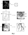
- step S3 a segmentation of 3D central line points in the 3D image is first carried out after the user has selected (S2) at least one start and/or end point M0 for the segmentation.
- Other 3D central line segmentation methods can also be used for this purpose, as described, for example, in O. Wink, W. J. Niessen and M. A. Viergever, "Minimum Cost Path Determination Using a Simple Heuristic Function" in Proc. International Conference on Pattern Recognition - 4, pp.
- the 3D central line points M obtained are projected forward into the 2D projections D used initially to reconstruct the 3D image, as is likewise shown in Fig. 2 by way of example for two 2D projections D1' and D2'.
- the projected-in 3D central line points Z1, Z2 can also be seen therein. Since these central line points Z1, Z2 have been projected in from the same 3D volume, and since the projection geometry with which the respective 2D projection was taken is known, the correspondences between the individual 3D central line points Z1, Z2 between the individual 2D projections D1', D2' are found automatically. There is thus no longer any need for a step to produce these correspondences individually, for example by means of complicated registering, for which purpose known methods use, for example, the so-called epipolar line method.
- the border points of the vessels H are then (S5) determined in each 2D projection D1', D2' on the basis of the central line points Z1, Z2.
- This may be effected, for example, using the gray value profiles in the 2D projections, since the gray value profile normally has an extremum at the borders of vessels. This step is not shown in any greater detail in Fig. 2.
- border points that have been found in the individual 2D projections D1' are then (S6) back-projected into the 3D image, with use again being made of the known correspondence of border points that are associated with one another on account of the known correspondence between the central line points Z1, Z2 in the 2D projections D1', D2'.
- a 3D model R, as shown in Fig. 2, of the vessel system can thus (S7) be modeled.
- a 3D model of a tubular structure can thus be created in a fully automatic manner, said 3D model having a high degree of accuracy on account of the use of the high-resolution 2D projections to determine border points of the tubular structure.
- the user need select just one start point for the segmentation of the 3D central line points in the 3D volume. Where appropriate, even this selection can be fully automated.
- the method according to the invention thus has a considerably lower computational complexity and requires considerably less user interactions while retaining the same degree of accuracy.
Landscapes
- Physics & Mathematics (AREA)
- Engineering & Computer Science (AREA)
- General Physics & Mathematics (AREA)
- Theoretical Computer Science (AREA)
- Geometry (AREA)
- Computer Graphics (AREA)
- Software Systems (AREA)
- Apparatus For Radiation Diagnosis (AREA)
- Image Generation (AREA)
- Image Processing (AREA)
Claims (9)
- Verfahren zur 3D-Modellierung einer dreidimensionalen röhrenförmigen Struktur eines Untersuchungsobjekts aus einer Anzahl von aus unterschiedlichen Projektionsrichtungen erfassten 2D-Projektionsbildern (D) der röhrenförmigen Struktur (H) mit den Schritten:a) Rekonstruktion eines 3D-Bildes (B) aus den 2D-Projektionsbildern (D),b) Auswahl mindestens eines in der röhrenförmigen Struktur (H) liegenden 3D-Zentrallinienpunktes (M0) in dem 3D-Bild (B),c) Segmentierung weiterer 3D-Zentrallinienpunkte (M) der röhrenförmigen Struktur (H) in dem 3D-Bild (B),d) Vorwärtsprojektion der in dem 3D-Bild (B) segmentierten 3D-Zentrallinienpunkte (M) in die 2D-Projektionsbilder (D'),e) Bestimmung von Randpunkten der röhrenförmigen Struktur (H) in den 2D-Projektionsbildern (D') anhand der hineinprojizierten 3D-Zentrallinienpunkte (Z) undf) Rückprojektion der Randpunkte aus den 2D-Projektionsbildern (D') in das 3D-Bild (B).
- Verfahren nach Anspruch 1, dadurch gekennzeichnet, dass in Schritt b) mindestens ein Anfangspunkt und ein Endpunkt einer 3D-Zentrallinie (M) in der röhrenförmigen Struktur (H) ausgewählt werden.
- Verfahren nach Anspruch 1, dadurch gekennzeichnet, dass das 3D-Bild (B) mit niedriger Auflösung rekonstruiert wird.
- Verfahren nach Anspruch 1, dadurch gekennzeichnet, dass die Bestimmung von Randpunkten der röhrenförmigen Struktur (H) in den 2D-Projektionsbildern (D) in Schritt e) automatisch erfolgt, insbesondere durch Berücksichtigung der Bildwerte entlang einem Querschnitt durch die röhrenförmige Struktur (H).
- Verfahren nach Anspruch 1, dadurch gekennzeichnet, dass parallel zur Erfassung der 2D-Projektionsbilder (D) ein eine periodische Bewegung des Untersuchungsobjekts repräsentierendes Bewegungssignal (E) aufgezeichnet wird und dass das 3D-Bild (B) aus in gleichen Bewegungsphasen erfassten 2D-Projektionsbildern (D) erstellt wird.
- Verfahren nach Anspruch 5, dadurch gekennzeichnet, dass als Bewegungssignal (E) ein Elektrokardiogramm oder ein Atembewegungssignal verwendet wird.
- Verfahren nach Anspruch 1, dadurch gekennzeichnet, dass das Verfahren zur Bildgebung der Herzkranzgefäße eines Patienten verwendet wird.
- Vorrichtung zur 3D-Modellierung einer dreidimensionalen röhrenförmigen Struktur eines Untersuchungsobjekts aus einer Anzahl von aus unterschiedlichen Projektionsrichtungen erfassten 2D-Projektionsbildern (D) der röhrenförmigen Struktur (H) mit:a) einer Rekonstruktionseinheit zur Rekonstruktion eines 3D-Bildes (B) aus den 2D-Projektionsbildern (D),b) Auswahlmitteln zur Auswahl mindestens eines in der röhrenförmigen Struktur (H) liegenden 3D-Zentrallinienpunktes (M0) in dem 3D-Bild (B),c) einer Segmentierungseinheit zur Segmentierung weiterer 3D-Zentrallinienpunkte (M) der röhrenförmigen Struktur (H) in dem 3D-Bild (B),d) einer Vorwärtsprojektionseinheit zur Vorwärtsprojektion der in dem 3D-Bild (B) segmentierten 3D-Zentrallinienpunkte (M) in die 2D-Projektionsbilder (D'),e) einer Randpunktbestimmungseinheit zur Bestimmung von Randpunkten der röhrenförmigen Struktur (H) in den 2D-Projektionsbildern (D') anhand der hineinprojizierten 3D-Zentrallinienpunkte (Z) undf) einer Rückprojektionseinheit zur Rückprojektion der Randpunkte aus den 2D-Projektionsbildern (D') in das 3D-Bild (B).
- Computerprogramm mit Computerprogrammmitteln zur Veranlassung eines Computers zur Ausführung der Schritte des Verfahrens nach Anspruch 1, wenn das Computerprogramm auf einem Computer ausgeführt wird.
Priority Applications (1)
| Application Number | Priority Date | Filing Date | Title |
|---|---|---|---|
| EP04707588A EP1595228B1 (de) | 2003-02-12 | 2004-02-03 | Methode zur drei-dimensionalen modellierung von rohrförmige n strukturen |
Applications Claiming Priority (4)
| Application Number | Priority Date | Filing Date | Title |
|---|---|---|---|
| EP03100306 | 2003-02-12 | ||
| EP03100306 | 2003-02-12 | ||
| PCT/IB2004/000261 WO2004072903A2 (en) | 2003-02-12 | 2004-02-03 | Method for the 3d modeling of a tubular structure |
| EP04707588A EP1595228B1 (de) | 2003-02-12 | 2004-02-03 | Methode zur drei-dimensionalen modellierung von rohrförmige n strukturen |
Publications (2)
| Publication Number | Publication Date |
|---|---|
| EP1595228A2 EP1595228A2 (de) | 2005-11-16 |
| EP1595228B1 true EP1595228B1 (de) | 2006-10-25 |
Family
ID=32865032
Family Applications (1)
| Application Number | Title | Priority Date | Filing Date |
|---|---|---|---|
| EP04707588A Expired - Lifetime EP1595228B1 (de) | 2003-02-12 | 2004-02-03 | Methode zur drei-dimensionalen modellierung von rohrförmige n strukturen |
Country Status (6)
| Country | Link |
|---|---|
| US (1) | US7574026B2 (de) |
| EP (1) | EP1595228B1 (de) |
| JP (1) | JP4468353B2 (de) |
| AT (1) | ATE343827T1 (de) |
| DE (1) | DE602004002939T2 (de) |
| WO (1) | WO2004072903A2 (de) |
Families Citing this family (68)
| Publication number | Priority date | Publication date | Assignee | Title |
|---|---|---|---|---|
| WO2007092054A2 (en) * | 2006-02-06 | 2007-08-16 | Specht Donald F | Method and apparatus to visualize the coronary arteries using ultrasound |
| US8473239B2 (en) * | 2009-04-14 | 2013-06-25 | Maui Imaging, Inc. | Multiple aperture ultrasound array alignment fixture |
| JP5121173B2 (ja) * | 2006-06-29 | 2013-01-16 | 株式会社東芝 | 3次元画像生成装置 |
| DE102006045423B4 (de) * | 2006-09-26 | 2016-07-14 | Siemens Healthcare Gmbh | 07.09.07Verfahren zur Nachbearbeitung eines dreidimensionalen Bilddatensatzes einer Gefäßstruktur |
| EP2074592B1 (de) | 2006-10-17 | 2011-04-20 | Philips Intellectual Property & Standards GmbH | Vierdimensionale rekonstruktion von mehrere phasen periodischer bewegung aufweisenden regionen |
| EP2088932B1 (de) | 2006-10-25 | 2020-04-08 | Maui Imaging, Inc. | Verfahren und vorrichtung zur herstellung von ultraschallbildern mithilfe mehrerer öffnungen |
| US8280125B2 (en) * | 2007-02-02 | 2012-10-02 | Siemens Aktiengesellschaft | Method and system for segmentation of tubular structures using pearl strings |
| EP1959391A1 (de) * | 2007-02-13 | 2008-08-20 | BrainLAB AG | Bestimmung des dreidimensionalen Verlaufs des Randes einer anatomischen Struktur |
| US8290247B2 (en) * | 2007-05-16 | 2012-10-16 | Siemens Aktiengesellschaft | Method and system for segmentation of tubular structures in 3D images |
| DE102007024154A1 (de) * | 2007-05-24 | 2008-11-27 | Siemens Ag | Verfahren zur automatischen Auswahl eines Darstellungsmodus für einen Bilddatensatz eines zu untersuchenden Organs |
| EP2175779A2 (de) * | 2007-07-11 | 2010-04-21 | Philips Intellectual Property & Standards GmbH | Verfahren zur erfassung dreidimensionaler bilder von koronargefässen, insbesondere von koronarvenen |
| US8934604B2 (en) * | 2007-09-28 | 2015-01-13 | Kabushiki Kaisha Toshiba | Image display apparatus and X-ray diagnostic apparatus |
| JP5269376B2 (ja) | 2007-09-28 | 2013-08-21 | 株式会社東芝 | 画像表示装置及びx線診断治療装置 |
| US9282945B2 (en) | 2009-04-14 | 2016-03-15 | Maui Imaging, Inc. | Calibration of ultrasound probes |
| US8200466B2 (en) | 2008-07-21 | 2012-06-12 | The Board Of Trustees Of The Leland Stanford Junior University | Method for tuning patient-specific cardiovascular simulations |
| JP5666446B2 (ja) | 2008-08-08 | 2015-02-12 | マウイ イマギング,インコーポレーテッド | マルチアパーチャ方式の医用超音波技術を用いた画像形成方法及びアドオンシステムの同期方法 |
| JP2010042065A (ja) * | 2008-08-08 | 2010-02-25 | Toshiba Corp | 医用画像処理装置、処理方法 |
| US9405886B2 (en) | 2009-03-17 | 2016-08-02 | The Board Of Trustees Of The Leland Stanford Junior University | Method for determining cardiovascular information |
| EP2408375B1 (de) | 2009-03-20 | 2017-12-06 | Orthoscan Incorporated | Bewegliche bildgebungsvorrichtung |
| WO2011103303A2 (en) | 2010-02-18 | 2011-08-25 | Maui Imaging, Inc. | Point source transmission and speed-of-sound correction using mult-aperture ultrasound imaging |
| US9082211B2 (en) * | 2010-05-06 | 2015-07-14 | The Regents Of The University Of California | Measurement of blood flow dynamics with X-ray computed tomography: dynamic CT angiography |
| US8157742B2 (en) | 2010-08-12 | 2012-04-17 | Heartflow, Inc. | Method and system for patient-specific modeling of blood flow |
| US8315812B2 (en) | 2010-08-12 | 2012-11-20 | Heartflow, Inc. | Method and system for patient-specific modeling of blood flow |
| US9589204B2 (en) * | 2010-09-20 | 2017-03-07 | Koninklijke Philips N.V. | Quantification of a characteristic of a lumen of a tubular structure |
| WO2012051305A2 (en) | 2010-10-13 | 2012-04-19 | Mau Imaging, Inc. | Multiple aperture probe internal apparatus and cable assemblies |
| EP2627257B1 (de) | 2010-10-13 | 2019-04-17 | Maui Imaging, Inc. | Konkave ultraschallwandler und 3d-arrays |
| US9125611B2 (en) | 2010-12-13 | 2015-09-08 | Orthoscan, Inc. | Mobile fluoroscopic imaging system |
| JP6000672B2 (ja) * | 2011-07-19 | 2016-10-05 | 東芝メディカルシステムズ株式会社 | 画像処理システム、画像保管装置及び医用画像診断装置 |
| CN104105449B (zh) | 2011-12-01 | 2018-07-17 | 毛伊图像公司 | 使用基于声脉冲和多孔多普勒超声的运动检测 |
| US9265484B2 (en) | 2011-12-29 | 2016-02-23 | Maui Imaging, Inc. | M-mode ultrasound imaging of arbitrary paths |
| CN107028623B (zh) | 2012-02-21 | 2020-09-01 | 毛伊图像公司 | 使用多孔超声确定材料刚度 |
| WO2013148673A1 (en) | 2012-03-26 | 2013-10-03 | Maui Imaging, Inc. | Systems and methods for improving ultrasound image quality by applying weighting factors |
| DE102012205935B4 (de) * | 2012-04-12 | 2018-11-15 | Siemens Healthcare Gmbh | Verfahren zur Aufnahme eines vierdimensionalen Angiographie-Datensatzes |
| US8548778B1 (en) | 2012-05-14 | 2013-10-01 | Heartflow, Inc. | Method and system for providing information from a patient-specific model of blood flow |
| EP2873060B1 (de) | 2012-07-10 | 2016-01-13 | Koninklijke Philips N.V. | Embolisationsvolumenrekonstruktion in der interventionellen radiografie |
| WO2014026185A1 (en) | 2012-08-10 | 2014-02-13 | Maui Imaging, Inc. | Calibration of multiple aperture ultrasound probes |
| KR102176319B1 (ko) | 2012-08-21 | 2020-11-09 | 마우이 이미징, 인코포레이티드 | 초음파 이미징 시스템 메모리 아키텍처 |
| US20140064513A1 (en) | 2012-09-06 | 2014-03-06 | MUSIC Group IP Ltd. | System and method for remotely controlling audio equipment |
| WO2014042902A1 (en) * | 2012-09-13 | 2014-03-20 | The Regents Of The University Of California | Lung, lobe, and fissure imaging systems and methods |
| US9943233B2 (en) | 2012-10-24 | 2018-04-17 | Cathworks Ltd. | Automated measurement system and method for coronary artery disease scoring |
| US10210956B2 (en) | 2012-10-24 | 2019-02-19 | Cathworks Ltd. | Diagnostically useful results in real time |
| JP6139116B2 (ja) * | 2012-11-30 | 2017-05-31 | 東芝メディカルシステムズ株式会社 | 医用画像処理装置 |
| JP5459886B2 (ja) * | 2013-01-25 | 2014-04-02 | 株式会社東芝 | 画像表示装置 |
| US9510806B2 (en) | 2013-03-13 | 2016-12-06 | Maui Imaging, Inc. | Alignment of ultrasound transducer arrays and multiple aperture probe assembly |
| WO2014163334A1 (ko) * | 2013-04-02 | 2014-10-09 | 재단법인 아산사회복지재단 | 물질특성에 기반한 전산유체역학 모델링 및 분석 방법 |
| US9883848B2 (en) | 2013-09-13 | 2018-02-06 | Maui Imaging, Inc. | Ultrasound imaging using apparent point-source transmit transducer |
| US10424063B2 (en) | 2013-10-24 | 2019-09-24 | CathWorks, LTD. | Vascular characteristic determination with correspondence modeling of a vascular tree |
| JP6722656B2 (ja) | 2014-08-18 | 2020-07-15 | マウイ イマギング,インコーポレーテッド | ネットワークベース超音波イメージングシステム |
| US20180214129A1 (en) * | 2014-09-08 | 2018-08-02 | Koninklijke Philips N.V. | Medical imaging apparatus |
| JP6545969B2 (ja) * | 2015-02-03 | 2019-07-17 | 株式会社日立製作所 | 超音波診断装置 |
| EP3277187B1 (de) | 2015-03-30 | 2022-05-04 | Maui Imaging, Inc. | Ultraschallbildgebungverfahren zur erkennung von objektbewegungen |
| EP3128481B1 (de) * | 2015-08-04 | 2019-12-18 | Pie Medical Imaging BV | Verfahren und vorrichtung zur verbesserung einer 3d+zeit-rekonstruktion |
| US11031136B2 (en) | 2015-08-05 | 2021-06-08 | Koninklijke Philips N.V. | Assistance device and method for an interventional hemodynamic measurement |
| US10856846B2 (en) | 2016-01-27 | 2020-12-08 | Maui Imaging, Inc. | Ultrasound imaging with sparse array probes |
| EP3220357A3 (de) * | 2016-03-15 | 2018-01-10 | Siemens Healthcare GmbH | Modellhaftes erzeugen und darstellen von dreidimensionalen objekten |
| EP3457930B1 (de) | 2016-05-16 | 2023-11-15 | Cathworks Ltd. | System zur beurteilung von blutgefässen |
| WO2017199246A1 (en) | 2016-05-16 | 2017-11-23 | Cathworks Ltd. | Vascular selection from images |
| DE102016215971A1 (de) * | 2016-08-25 | 2018-03-01 | Siemens Healthcare Gmbh | Segmentierung einer Angiographie unter Verwendung einer bestehenden dreidimensionalen Rekonstruktion |
| EP3948886B1 (de) | 2019-04-01 | 2025-10-29 | CathWorks Ltd. | Verfahren und vorrichtung zur auswahl von angiografischen bildern |
| WO2021059165A1 (en) | 2019-09-23 | 2021-04-01 | Cathworks Ltd. | Methods, apparatus, and system for synchronization between a three-dimensional vascular model and an imaging device |
| JP7724853B2 (ja) | 2020-10-21 | 2025-08-18 | マウイ イマギング,インコーポレーテッド | 多数開口超音波を用いた組織の特徴付けのためのシステム及び方法 |
| EP4236811A4 (de) | 2020-11-02 | 2024-10-09 | Maui Imaging, Inc. | Systeme und verfahren zur verbesserung der ultraschallbildqualität |
| WO2022236506A1 (en) * | 2021-05-08 | 2022-11-17 | Siemens Industry Software Inc. | Modeling method and system for tubular structure, and computer-readable storage medium thereof |
| US12315076B1 (en) | 2021-09-22 | 2025-05-27 | Cathworks Ltd. | Four-dimensional motion analysis of a patient's coronary arteries and myocardial wall |
| KR20240148399A (ko) | 2022-02-10 | 2024-10-11 | 캐스웍스 엘티디. | 기계 학습 기반 센서 분석 및 혈관 트리 분할을 위한 시스템 및 방법 |
| IL326432A (en) | 2023-08-09 | 2026-04-01 | Cathworks Ltd | Post-pci coronary analysis |
| KR20260052078A (ko) | 2023-08-09 | 2026-04-17 | 캐스웍스 엘티디. | 혈관 지수 측정을 위한 향상된 사용자 인터페이스 및 크로스토크 분석 |
| US12567489B2 (en) | 2024-06-12 | 2026-03-03 | Cathworks Ltd. | Systems and methods for displaying distal fractional flow reserve values in vascular analysis |
Family Cites Families (7)
| Publication number | Priority date | Publication date | Assignee | Title |
|---|---|---|---|---|
| US6047080A (en) * | 1996-06-19 | 2000-04-04 | Arch Development Corporation | Method and apparatus for three-dimensional reconstruction of coronary vessels from angiographic images |
| US6148095A (en) * | 1997-09-08 | 2000-11-14 | University Of Iowa Research Foundation | Apparatus and method for determining three-dimensional representations of tortuous vessels |
| US6928314B1 (en) * | 1998-01-23 | 2005-08-09 | Mayo Foundation For Medical Education And Research | System for two-dimensional and three-dimensional imaging of tubular structures in the human body |
| FR2797978B1 (fr) | 1999-08-30 | 2001-10-26 | Ge Medical Syst Sa | Procede de recalage automatique d'images |
| FR2799030B1 (fr) * | 1999-09-24 | 2002-01-04 | Ge Medical Syst Sa | Procede de reconstruction d'une image tridimensionnelle d'un element d'interet, par exemple un elargisseur vasculaire insere dans un vaisseau |
| US7079132B2 (en) * | 2001-08-16 | 2006-07-18 | Siemens Corporate Reseach Inc. | System and method for three-dimensional (3D) reconstruction from ultrasound images |
| US7620501B2 (en) * | 2004-05-06 | 2009-11-17 | Siemens Medical Solutions Usa, Inc. | Artery-vein separation and vessel modeling |
-
2004
- 2004-01-23 US US10/545,184 patent/US7574026B2/en not_active Expired - Lifetime
- 2004-02-03 AT AT04707588T patent/ATE343827T1/de not_active IP Right Cessation
- 2004-02-03 WO PCT/IB2004/000261 patent/WO2004072903A2/en not_active Ceased
- 2004-02-03 JP JP2006502389A patent/JP4468353B2/ja not_active Expired - Lifetime
- 2004-02-03 EP EP04707588A patent/EP1595228B1/de not_active Expired - Lifetime
- 2004-02-03 DE DE602004002939T patent/DE602004002939T2/de not_active Expired - Lifetime
Also Published As
| Publication number | Publication date |
|---|---|
| US20060159326A1 (en) | 2006-07-20 |
| WO2004072903A3 (en) | 2004-11-25 |
| DE602004002939D1 (de) | 2006-12-07 |
| WO2004072903A2 (en) | 2004-08-26 |
| JP2006517822A (ja) | 2006-08-03 |
| EP1595228A2 (de) | 2005-11-16 |
| JP4468353B2 (ja) | 2010-05-26 |
| ATE343827T1 (de) | 2006-11-15 |
| DE602004002939T2 (de) | 2007-06-21 |
| US7574026B2 (en) | 2009-08-11 |
Similar Documents
| Publication | Publication Date | Title |
|---|---|---|
| US7574026B2 (en) | Method for the 3d modeling of a tubular structure | |
| CN101036165B (zh) | 用于树模型显像以检测肺栓塞的系统和方法 | |
| US7646900B2 (en) | Device and method for generating a three dimensional vascular model | |
| JP5268365B2 (ja) | 脈管幾何形状及び流れ特性を決定するシステム | |
| US20060036167A1 (en) | Vascular image processing | |
| US20080205722A1 (en) | Method and Apparatus for Automatic 4D Coronary Modeling and Motion Vector Field Estimation | |
| CN104252714B (zh) | 时变数据的重建 | |
| JP5345934B2 (ja) | 観察のための三次元レンダリングからのデータ集合の選択 | |
| JP2017077455A (ja) | 3d+時間再構成を改良する方法および装置 | |
| CN1672179A (zh) | 最佳视图v.o.01 | |
| US20110052035A1 (en) | Vessel Extraction Method For Rotational Angiographic X-ray Sequences | |
| US8098919B2 (en) | Three-dimensional reconstruction of an object from projection photographs | |
| JP2025542151A (ja) | 管状構造物の3dモデルからの中心線計算のためのコンピュータ実施による方法、コンピュータプログラム及びイメージングシステム | |
| Müller et al. | Evaluation of interpolation methods for surface‐based motion compensated tomographic reconstruction for cardiac angiographic C‐arm data | |
| CN101151638B (zh) | 用于分割数据集中的结构的方法和系统 | |
| CN107170021B (zh) | 时变数据的细化重构 | |
| JP4564387B2 (ja) | 医用画像生成装置 | |
| Keil et al. | Dynamic cone-beam reconstruction using a variational level set formulation | |
| Koland et al. | 3D Reconstruction of Coronary Vessel Trees from Biplanar X-Ray Images Using a Geometric Approach | |
| CN121883660A (zh) | 一种颈动脉超声时空重建方法及装置 | |
| EP3229210A2 (de) | Verfahren und vorrichtung zur bearbeitung der daten medizinischer bilder zur bestimmung eines geometrischen modells eines anatomischen volumenobjekts |
Legal Events
| Date | Code | Title | Description |
|---|---|---|---|
| PUAI | Public reference made under article 153(3) epc to a published international application that has entered the european phase |
Free format text: ORIGINAL CODE: 0009012 |
|
| 17P | Request for examination filed |
Effective date: 20050912 |
|
| AK | Designated contracting states |
Kind code of ref document: A2 Designated state(s): AT BE BG CH CY CZ DE DK EE ES FI FR GB GR HU IE IT LI LU MC NL PT RO SE SI SK TR |
|
| AX | Request for extension of the european patent |
Extension state: AL LT LV MK |
|
| GRAP | Despatch of communication of intention to grant a patent |
Free format text: ORIGINAL CODE: EPIDOSNIGR1 |
|
| DAX | Request for extension of the european patent (deleted) | ||
| RAP1 | Party data changed (applicant data changed or rights of an application transferred) |
Owner name: PHILIPS INTELLECTUAL PROPERTY & STANDARDS GMBH Owner name: KONINKLIJKE PHILIPS ELECTRONICS N.V. |
|
| GRAS | Grant fee paid |
Free format text: ORIGINAL CODE: EPIDOSNIGR3 |
|
| GRAA | (expected) grant |
Free format text: ORIGINAL CODE: 0009210 |
|
| AK | Designated contracting states |
Kind code of ref document: B1 Designated state(s): AT BE BG CH CY CZ DE DK EE ES FI FR GB GR HU IE IT LI LU MC NL PT RO SE SI SK TR |
|
| PG25 | Lapsed in a contracting state [announced via postgrant information from national office to epo] |
Ref country code: IT Free format text: LAPSE BECAUSE OF FAILURE TO SUBMIT A TRANSLATION OF THE DESCRIPTION OR TO PAY THE FEE WITHIN THE PRESCRIBED TIME-LIMIT;WARNING: LAPSES OF ITALIAN PATENTS WITH EFFECTIVE DATE BEFORE 2007 MAY HAVE OCCURRED AT ANY TIME BEFORE 2007. THE CORRECT EFFECTIVE DATE MAY BE DIFFERENT FROM THE ONE RECORDED. Effective date: 20061025 Ref country code: AT Free format text: LAPSE BECAUSE OF FAILURE TO SUBMIT A TRANSLATION OF THE DESCRIPTION OR TO PAY THE FEE WITHIN THE PRESCRIBED TIME-LIMIT Effective date: 20061025 Ref country code: CZ Free format text: LAPSE BECAUSE OF FAILURE TO SUBMIT A TRANSLATION OF THE DESCRIPTION OR TO PAY THE FEE WITHIN THE PRESCRIBED TIME-LIMIT Effective date: 20061025 Ref country code: CH Free format text: LAPSE BECAUSE OF FAILURE TO SUBMIT A TRANSLATION OF THE DESCRIPTION OR TO PAY THE FEE WITHIN THE PRESCRIBED TIME-LIMIT Effective date: 20061025 Ref country code: BE Free format text: LAPSE BECAUSE OF FAILURE TO SUBMIT A TRANSLATION OF THE DESCRIPTION OR TO PAY THE FEE WITHIN THE PRESCRIBED TIME-LIMIT Effective date: 20061025 Ref country code: FI Free format text: LAPSE BECAUSE OF FAILURE TO SUBMIT A TRANSLATION OF THE DESCRIPTION OR TO PAY THE FEE WITHIN THE PRESCRIBED TIME-LIMIT Effective date: 20061025 Ref country code: LI Free format text: LAPSE BECAUSE OF FAILURE TO SUBMIT A TRANSLATION OF THE DESCRIPTION OR TO PAY THE FEE WITHIN THE PRESCRIBED TIME-LIMIT Effective date: 20061025 Ref country code: SI Free format text: LAPSE BECAUSE OF FAILURE TO SUBMIT A TRANSLATION OF THE DESCRIPTION OR TO PAY THE FEE WITHIN THE PRESCRIBED TIME-LIMIT Effective date: 20061025 Ref country code: SK Free format text: LAPSE BECAUSE OF FAILURE TO SUBMIT A TRANSLATION OF THE DESCRIPTION OR TO PAY THE FEE WITHIN THE PRESCRIBED TIME-LIMIT Effective date: 20061025 Ref country code: RO Free format text: LAPSE BECAUSE OF FAILURE TO SUBMIT A TRANSLATION OF THE DESCRIPTION OR TO PAY THE FEE WITHIN THE PRESCRIBED TIME-LIMIT Effective date: 20061025 |
|
| REG | Reference to a national code |
Ref country code: GB Ref legal event code: FG4D |
|
| REG | Reference to a national code |
Ref country code: CH Ref legal event code: EP |
|
| REG | Reference to a national code |
Ref country code: IE Ref legal event code: FG4D |
|
| REF | Corresponds to: |
Ref document number: 602004002939 Country of ref document: DE Date of ref document: 20061207 Kind code of ref document: P |
|
| PG25 | Lapsed in a contracting state [announced via postgrant information from national office to epo] |
Ref country code: BG Free format text: LAPSE BECAUSE OF FAILURE TO SUBMIT A TRANSLATION OF THE DESCRIPTION OR TO PAY THE FEE WITHIN THE PRESCRIBED TIME-LIMIT Effective date: 20070125 Ref country code: SE Free format text: LAPSE BECAUSE OF FAILURE TO SUBMIT A TRANSLATION OF THE DESCRIPTION OR TO PAY THE FEE WITHIN THE PRESCRIBED TIME-LIMIT Effective date: 20070125 Ref country code: DK Free format text: LAPSE BECAUSE OF FAILURE TO SUBMIT A TRANSLATION OF THE DESCRIPTION OR TO PAY THE FEE WITHIN THE PRESCRIBED TIME-LIMIT Effective date: 20070125 |
|
| PG25 | Lapsed in a contracting state [announced via postgrant information from national office to epo] |
Ref country code: ES Free format text: LAPSE BECAUSE OF FAILURE TO SUBMIT A TRANSLATION OF THE DESCRIPTION OR TO PAY THE FEE WITHIN THE PRESCRIBED TIME-LIMIT Effective date: 20070205 |
|
| PG25 | Lapsed in a contracting state [announced via postgrant information from national office to epo] |
Ref country code: MC Free format text: LAPSE BECAUSE OF NON-PAYMENT OF DUE FEES Effective date: 20070228 |
|
| PG25 | Lapsed in a contracting state [announced via postgrant information from national office to epo] |
Ref country code: PT Free format text: LAPSE BECAUSE OF FAILURE TO SUBMIT A TRANSLATION OF THE DESCRIPTION OR TO PAY THE FEE WITHIN THE PRESCRIBED TIME-LIMIT Effective date: 20070326 |
|
| REG | Reference to a national code |
Ref country code: CH Ref legal event code: PL |
|
| ET | Fr: translation filed | ||
| PLBE | No opposition filed within time limit |
Free format text: ORIGINAL CODE: 0009261 |
|
| STAA | Information on the status of an ep patent application or granted ep patent |
Free format text: STATUS: NO OPPOSITION FILED WITHIN TIME LIMIT |
|
| 26N | No opposition filed |
Effective date: 20070726 |
|
| PG25 | Lapsed in a contracting state [announced via postgrant information from national office to epo] |
Ref country code: IE Free format text: LAPSE BECAUSE OF NON-PAYMENT OF DUE FEES Effective date: 20070205 |
|
| PG25 | Lapsed in a contracting state [announced via postgrant information from national office to epo] |
Ref country code: GR Free format text: LAPSE BECAUSE OF FAILURE TO SUBMIT A TRANSLATION OF THE DESCRIPTION OR TO PAY THE FEE WITHIN THE PRESCRIBED TIME-LIMIT Effective date: 20070126 |
|
| PGFP | Annual fee paid to national office [announced via postgrant information from national office to epo] |
Ref country code: FR Payment date: 20070226 Year of fee payment: 4 |
|
| NLV4 | Nl: lapsed or anulled due to non-payment of the annual fee |
Effective date: 20080901 |
|
| PG25 | Lapsed in a contracting state [announced via postgrant information from national office to epo] |
Ref country code: NL Free format text: LAPSE BECAUSE OF NON-PAYMENT OF DUE FEES Effective date: 20080901 |
|
| REG | Reference to a national code |
Ref country code: FR Ref legal event code: ST Effective date: 20081031 |
|
| PG25 | Lapsed in a contracting state [announced via postgrant information from national office to epo] |
Ref country code: EE Free format text: LAPSE BECAUSE OF FAILURE TO SUBMIT A TRANSLATION OF THE DESCRIPTION OR TO PAY THE FEE WITHIN THE PRESCRIBED TIME-LIMIT Effective date: 20061025 |
|
| PG25 | Lapsed in a contracting state [announced via postgrant information from national office to epo] |
Ref country code: FR Free format text: LAPSE BECAUSE OF NON-PAYMENT OF DUE FEES Effective date: 20080229 |
|
| PG25 | Lapsed in a contracting state [announced via postgrant information from national office to epo] |
Ref country code: CY Free format text: LAPSE BECAUSE OF FAILURE TO SUBMIT A TRANSLATION OF THE DESCRIPTION OR TO PAY THE FEE WITHIN THE PRESCRIBED TIME-LIMIT Effective date: 20061025 Ref country code: LU Free format text: LAPSE BECAUSE OF NON-PAYMENT OF DUE FEES Effective date: 20070203 |
|
| PG25 | Lapsed in a contracting state [announced via postgrant information from national office to epo] |
Ref country code: HU Free format text: LAPSE BECAUSE OF FAILURE TO SUBMIT A TRANSLATION OF THE DESCRIPTION OR TO PAY THE FEE WITHIN THE PRESCRIBED TIME-LIMIT Effective date: 20070426 Ref country code: TR Free format text: LAPSE BECAUSE OF FAILURE TO SUBMIT A TRANSLATION OF THE DESCRIPTION OR TO PAY THE FEE WITHIN THE PRESCRIBED TIME-LIMIT Effective date: 20061025 |
|
| REG | Reference to a national code |
Ref country code: DE Ref legal event code: R081 Ref document number: 602004002939 Country of ref document: DE Owner name: PHILIPS GMBH, DE Free format text: FORMER OWNER: PHILIPS INTELLECTUAL PROPERTY & STANDARDS GMBH, 20099 HAMBURG, DE Effective date: 20140327 Ref country code: DE Ref legal event code: R082 Ref document number: 602004002939 Country of ref document: DE Representative=s name: MEISSNER, BOLTE & PARTNER GBR, DE Effective date: 20140327 Ref country code: DE Ref legal event code: R081 Ref document number: 602004002939 Country of ref document: DE Owner name: PHILIPS DEUTSCHLAND GMBH, DE Free format text: FORMER OWNER: PHILIPS INTELLECTUAL PROPERTY & STANDARDS GMBH, 20099 HAMBURG, DE Effective date: 20140327 Ref country code: DE Ref legal event code: R082 Ref document number: 602004002939 Country of ref document: DE Representative=s name: MEISSNER BOLTE PATENTANWAELTE RECHTSANWAELTE P, DE Effective date: 20140327 |
|
| REG | Reference to a national code |
Ref country code: DE Ref legal event code: R082 Ref document number: 602004002939 Country of ref document: DE Representative=s name: MEISSNER, BOLTE & PARTNER GBR, DE Ref country code: DE Ref legal event code: R081 Ref document number: 602004002939 Country of ref document: DE Owner name: PHILIPS GMBH, DE Free format text: FORMER OWNER: PHILIPS DEUTSCHLAND GMBH, 20099 HAMBURG, DE Ref country code: DE Ref legal event code: R082 Ref document number: 602004002939 Country of ref document: DE Representative=s name: MEISSNER BOLTE PATENTANWAELTE RECHTSANWAELTE P, DE |
|
| REG | Reference to a national code |
Ref country code: DE Ref legal event code: R082 Ref document number: 602004002939 Country of ref document: DE Representative=s name: MEISSNER BOLTE PATENTANWAELTE RECHTSANWAELTE P, DE Ref country code: DE Ref legal event code: R081 Ref document number: 602004002939 Country of ref document: DE Owner name: PHILIPS GMBH, DE Free format text: FORMER OWNER: PHILIPS GMBH, 20099 HAMBURG, DE |
|
| PGFP | Annual fee paid to national office [announced via postgrant information from national office to epo] |
Ref country code: GB Payment date: 20230214 Year of fee payment: 20 Ref country code: DE Payment date: 20220628 Year of fee payment: 20 |
|
| REG | Reference to a national code |
Ref country code: DE Ref legal event code: R071 Ref document number: 602004002939 Country of ref document: DE |
|
| REG | Reference to a national code |
Ref country code: GB Ref legal event code: PE20 Expiry date: 20240202 |
|
| PG25 | Lapsed in a contracting state [announced via postgrant information from national office to epo] |
Ref country code: GB Free format text: LAPSE BECAUSE OF EXPIRATION OF PROTECTION Effective date: 20240202 |