EP1594390B1 - Apparatus for regulating pressure during medical procedures - Google Patents
Apparatus for regulating pressure during medical procedures Download PDFInfo
- Publication number
- EP1594390B1 EP1594390B1 EP04700200A EP04700200A EP1594390B1 EP 1594390 B1 EP1594390 B1 EP 1594390B1 EP 04700200 A EP04700200 A EP 04700200A EP 04700200 A EP04700200 A EP 04700200A EP 1594390 B1 EP1594390 B1 EP 1594390B1
- Authority
- EP
- European Patent Office
- Prior art keywords
- pressure
- inner volume
- housing
- vein
- aperture
- Prior art date
- Legal status (The legal status is an assumption and is not a legal conclusion. Google has not performed a legal analysis and makes no representation as to the accuracy of the status listed.)
- Expired - Lifetime
Links
- 230000001105 regulatory effect Effects 0.000 title claims abstract description 16
- 238000000034 method Methods 0.000 title abstract description 28
- 230000008878 coupling Effects 0.000 claims abstract description 7
- 238000010168 coupling process Methods 0.000 claims abstract description 7
- 238000005859 coupling reaction Methods 0.000 claims abstract description 7
- 239000012530 fluid Substances 0.000 claims description 23
- 239000007788 liquid Substances 0.000 claims description 6
- 210000003462 vein Anatomy 0.000 abstract description 43
- 210000001367 artery Anatomy 0.000 abstract description 4
- 210000003752 saphenous vein Anatomy 0.000 description 7
- 238000001356 surgical procedure Methods 0.000 description 7
- 206010000060 Abdominal distension Diseases 0.000 description 5
- 238000003306 harvesting Methods 0.000 description 5
- 238000005086 pumping Methods 0.000 description 5
- 230000008901 benefit Effects 0.000 description 4
- 230000008569 process Effects 0.000 description 4
- 230000003511 endothelial effect Effects 0.000 description 3
- 239000000523 sample Substances 0.000 description 3
- 201000001320 Atherosclerosis Diseases 0.000 description 2
- 102000002262 Thromboplastin Human genes 0.000 description 2
- 108010000499 Thromboplastin Proteins 0.000 description 2
- 102000003978 Tissue Plasminogen Activator Human genes 0.000 description 2
- 108090000373 Tissue Plasminogen Activator Proteins 0.000 description 2
- 230000002612 cardiopulmonary effect Effects 0.000 description 2
- 238000004891 communication Methods 0.000 description 2
- 201000010099 disease Diseases 0.000 description 2
- 208000037265 diseases, disorders, signs and symptoms Diseases 0.000 description 2
- 210000002889 endothelial cell Anatomy 0.000 description 2
- 238000002347 injection Methods 0.000 description 2
- 239000007924 injection Substances 0.000 description 2
- 238000004519 manufacturing process Methods 0.000 description 2
- 239000000463 material Substances 0.000 description 2
- 230000004048 modification Effects 0.000 description 2
- 238000012986 modification Methods 0.000 description 2
- 239000004033 plastic Substances 0.000 description 2
- 229960000187 tissue plasminogen activator Drugs 0.000 description 2
- 239000005526 vasoconstrictor agent Substances 0.000 description 2
- 206010002383 Angina Pectoris Diseases 0.000 description 1
- 102000004127 Cytokines Human genes 0.000 description 1
- 108090000695 Cytokines Proteins 0.000 description 1
- 102000002045 Endothelin Human genes 0.000 description 1
- 108050009340 Endothelin Proteins 0.000 description 1
- 102100033902 Endothelin-1 Human genes 0.000 description 1
- 101800004490 Endothelin-1 Proteins 0.000 description 1
- 102000009123 Fibrin Human genes 0.000 description 1
- 108010073385 Fibrin Proteins 0.000 description 1
- BWGVNKXGVNDBDI-UHFFFAOYSA-N Fibrin monomer Chemical compound CNC(=O)CNC(=O)CN BWGVNKXGVNDBDI-UHFFFAOYSA-N 0.000 description 1
- 206010051269 Graft thrombosis Diseases 0.000 description 1
- 208000031481 Pathologic Constriction Diseases 0.000 description 1
- 208000005392 Spasm Diseases 0.000 description 1
- 208000007536 Thrombosis Diseases 0.000 description 1
- 206010047139 Vasoconstriction Diseases 0.000 description 1
- 206010047163 Vasospasm Diseases 0.000 description 1
- 238000009825 accumulation Methods 0.000 description 1
- 230000004075 alteration Effects 0.000 description 1
- 210000004369 blood Anatomy 0.000 description 1
- 239000008280 blood Substances 0.000 description 1
- 230000006727 cell loss Effects 0.000 description 1
- 230000015271 coagulation Effects 0.000 description 1
- 238000005345 coagulation Methods 0.000 description 1
- 230000001276 controlling effect Effects 0.000 description 1
- 230000001419 dependent effect Effects 0.000 description 1
- 239000003814 drug Substances 0.000 description 1
- 229940079593 drug Drugs 0.000 description 1
- ZUBDGKVDJUIMQQ-UBFCDGJISA-N endothelin-1 Chemical compound C([C@@H](C(=O)N[C@@H](CC(C)C)C(=O)N[C@@H](CC(O)=O)C(=O)N[C@@H]([C@@H](C)CC)C(=O)N[C@@H]([C@@H](C)CC)C(=O)N[C@@H](CC=1C2=CC=CC=C2NC=1)C(O)=O)NC(=O)[C@H]1NC(=O)[C@H](CC=2C=CC=CC=2)NC(=O)[C@@H](CC=2C=CC(O)=CC=2)NC(=O)[C@H](C(C)C)NC(=O)[C@H]2CSSC[C@@H](C(N[C@H](CO)C(=O)N[C@@H](CO)C(=O)N[C@H](CC(C)C)C(=O)N[C@@H](CCSC)C(=O)N[C@H](CC(O)=O)C(=O)N[C@@H](CCCCN)C(=O)N[C@@H](CCC(O)=O)C(=O)N2)=O)NC(=O)[C@@H](CO)NC(=O)[C@H](N)CSSC1)C1=CNC=N1 ZUBDGKVDJUIMQQ-UBFCDGJISA-N 0.000 description 1
- 229950003499 fibrin Drugs 0.000 description 1
- 230000002706 hydrostatic effect Effects 0.000 description 1
- 206010020718 hyperplasia Diseases 0.000 description 1
- 238000002513 implantation Methods 0.000 description 1
- 230000002757 inflammatory effect Effects 0.000 description 1
- 230000000977 initiatory effect Effects 0.000 description 1
- 230000007246 mechanism Effects 0.000 description 1
- 239000002184 metal Substances 0.000 description 1
- 208000031225 myocardial ischemia Diseases 0.000 description 1
- 210000000440 neutrophil Anatomy 0.000 description 1
- 230000035515 penetration Effects 0.000 description 1
- 230000003389 potentiating effect Effects 0.000 description 1
- 230000009467 reduction Effects 0.000 description 1
- 230000004044 response Effects 0.000 description 1
- 230000000284 resting effect Effects 0.000 description 1
- 230000000250 revascularization Effects 0.000 description 1
- 238000000518 rheometry Methods 0.000 description 1
- 239000002356 single layer Substances 0.000 description 1
- 230000036262 stenosis Effects 0.000 description 1
- 208000037804 stenosis Diseases 0.000 description 1
- 238000007892 surgical revascularization Methods 0.000 description 1
- 208000024891 symptom Diseases 0.000 description 1
Images


Classifications
-
- A—HUMAN NECESSITIES
- A61—MEDICAL OR VETERINARY SCIENCE; HYGIENE
- A61B—DIAGNOSIS; SURGERY; IDENTIFICATION
- A61B90/00—Instruments, implements or accessories specially adapted for surgery or diagnosis and not covered by any of the groups A61B1/00 - A61B50/00, e.g. for luxation treatment or for protecting wound edges
- A61B90/03—Automatic limiting or abutting means, e.g. for safety
- A61B2090/032—Automatic limiting or abutting means, e.g. for safety pressure limiting, e.g. hydrostatic
Definitions
- This invention generally relates to medical procedures including the application of a pressure and, especially, to the field of vein grafting and preparation of a vein during vein grafting.
- angina recurs in up to 20% of patients during the first year after bypass surgery using saphenous vein grafting and in 4% of patients annually during the ensuing 5 years. Further revascularization, either reoperative bypass surgery or percutaneous intervention, is required in 4% of patients by 5 years, 19% of patients by 10 years, and 31% of patients by 12 years after initial bypass surgery.
- “Saphenous vein graft disease” is composed of three discrete processes: thrombosis, intimal hyperplasia, and atherosclerosis. These processes, although more or less temporally distinct, are interlinked pathophysiologically in the evolution of vein graft disease. Between 3% and 12% of saphenous vein grafts occlude, with or without symptoms, within the first month after bypass surgery. At this early stage, the principal underlying mechanism is graft thrombosis caused by a combination of alterations in the vessel wall, changes in blood rheology, and altered flow dynamics, as classically defined in Virchow's triad.
- Endothelial loss also activates the extrinsic coagulation cascade by tissue factor that is constitutively expressed in the exposed subendothelium. Tissue factor is also expressed, within 2 hours of initiating cardiopulmonary bypass, on the surfaces of endothelial cells activated by inflammatory cytokines.
- saphenous veins particularly when denuded, are highly sensitive to circulating vasoconstrictors, including the most potent endogenous vasoconstrictor, endothelin.
- the circulating concentration of endothelin-1 shows a marked initial rise, followed by an additional slower increment, after the onset of cardiopulmonary bypass and the resulting venoconstriction response may further attenuate flow and promote stasis.
- US 4,403,988 discloses a syringe assembly with a syringe and means for limiting the amount of pressure generated by the syringe during pumping of fluid.
- Figs. 9 and 10 show an adapter for a syringe with a passageway for fluid from the syringe. A channel communicating with the passageway and the outside of the adapter can be blocked by a valve. However, when the pressure in the passageway exceeds a predetermined threshold, the valve releases liquid through the channel.
- US 4,623,335 describes an apparatus for detecting probe penetration of human tissue having a predetermined internal pressure. The apparatus comprises an elongate probe connected to means for pumping medication.
- the apparatus comprises a conduit in communication with the pumping means and the probe, in which a spring-biased piston slidably resides.
- a spring-biased piston slidably resides.
- the assembly comprises a syringe for pumping fluid from a reservoir into an injection needle.
- the syringe is connected to two openings that communicate with the reservoir and the needle, respectively.
- each orifice comprises a spring-biased piston.
- the shape of the pistons is adapted to avoid any jamming.
- EP 0 032 826 shows a vein distention apparatus comprising a syringe and a cannula for injecting fluid into a vein to be transplanted.
- the apparatus further comprises pressure limiting means with a fluid path connecting the syringe and the cannula.
- the limiting means are constituted mainly by an expandable reservoir that inflates when the pressure in the fluid path exceeds a certain threshold, thus limiting the pressure.
- the invention provides an apparatus according to claim 1. Further embodiments of the invention a described in the dependent claims.
- the apparatus includes a first element for inserting liquid into a vein, the first element including an inelastic housing enclosing an inner volume.
- the apparatus further includes a second element for regulating pressure within the first and second elements, the second element including an inelastic housing enclosing an inner volume.
- the second element is coupled to the first element such that the inner volume of the second element is continuous with the inner volume of the first element.
- the apparatus further includes a pressure sensor or pressure-operated valve coupled to the second element for measuring pressure within the inner volume of the second element
- the apparatus further includes a valve coupled to the second element and providing access to the inner volume of the second element. If the pressure sensor senses or is exposed to pressure above a threshold, the valve releases pressure from the inner volumes of the first and second elements.
- the method for preparing a vein for grafting includes extracting a portion of a vein and connecting a first end of the vein that was extracted to a coupling. A seal is created between the coupling and the vein and the coupling provides access to an inner volume of the vein.
- the method further includes occluding the second end of the vein and inserting a liquid into the vein via the coupling using an apparatus.
- the apparatus includes a first element for inserting liquid into a vein, the first element including an inelastic housing enclosing an inner volume.
- the apparatus further includes a second element for regulating pressure within the first and second elements, the second element including an inelastic housing enclosing an inner volume.
- the second element is coupled to the first element such that the inner volume of the second element is continuous with the inner volume of the first element.
- the apparatus further includes a pressure sensor or pressure-operated valve coupled to the second element for measuring pressure within the inner volume of the second element a valve coupled to the second element and providing access to the inner volume of the second element. If the pressure sensor senses or is exposed to pressure above a threshold, the valve releases pressure from the inner volumes of the first and second elements.
- An apparatus for regulating intravascular pressure during vein distention includes an inelastic housing enclosing an inner volume, the housing having a first and second end.
- the apparatus further includes an aperture on the first end of the housing, the aperture for coupling to an element having an inner volume such that the inner volume of the housing is continuous with the inner volume of the element.
- the apparatus further includes a pressure sensor or pressure-operated valve coupled to the housing for measuring pressure within the inner volume of the housing and a valve coupled to the housing and providing access to the inner volume of the housing. If the pressure sensor senses or is exposed to pressure above a threshold, the valve releases pressure from within the inner volume of the housing.
- the aforementioned apparatus are not only aids in safe distention of vein grafts, but are also cost-effective, easy to use, and reliable. Further, the apparatus is well suited to safe application of pressure in other medical procedures as well.
- FIG. 1 schematically illustrates an apparatus not in accordance with the present invention
- FIG. 2 is an exploded view of the apparatus of Figure 1 ;
- FIG. 3 shows an embodiment of an apparatus in accordance with the present invention which provides for adjustable setting of the maximum pressure
- FIGS 4-6 illustrate aspects of the present invention for use in regulating the maximum negative pressure.
- the invention relates to an apparatus for controlling the application of pressure during a medical procedure so as to reliably control or regulate the maximum pressure, or maximum negative pressure, which is applied during such a procedure.
- one area where such an apparatus has excellent advantage in use is during preparation of a vein graft, since limiting the application of excessive pressure can provide a conduit such as a vein or artery which is significantly less damaged than such a conduit harvested using conventional processes that can expose the conduit to excessive pressure.
- the present invention overcomes problems with the prior art by providing a vein graft preparation apparatus that controls pressure within a vein graft during the distention process.
- a portion of a conduit such as a vein or artery is extracted and connected to the apparatus of the present invention at one end.
- the other end is occluded, and fluid is inserted into the conduit to distend same.
- the apparatus of the present invention serves to regulate pressure applied to the conduit by the fluid.
- FIG. 1 illustrates a vein graft preparation apparatus 10.
- the apparatus 10 includes a first-element, in this case a standard syringe 12, for inserting fluid, preferably liquid, into the vein, and a second or pressure regulation element 14 used in conjunction with vein graft preparation apparatus 10.
- Pressure regulation element 14 includes a plastic cylinder 16 that attaches and locks into a three-way "stopcock" 18 with syringe 12.
- the pressure regulation element 14 preferably attaches substantially perpendicular to the syringe 12 that will be injecting fluid to the vein.
- the conduit is monitored for leakage from side branches or the like. If such leakage is detected, the side branch can be occluded so as to improve the conduit for subsequent use.
- Pressure regulation element 14 is open on one end 20 in order to attach to stopcock 18, and is closed on the opposite end 22.
- a pressure operated valve is advantageously coupled, either directly or in fluid communication with, element 14.
- This valve can be provided as follows. Within cylinder 16, there is a rubber stopper or piston 24 that sits on one end of a metal coil or spring 26. The rubber stopper is located nearer to open end 20 of the cylinder 16, in its resting position. On a lateral side of the cylinder, there is an orifice or opening 28 that can extend preferably substantially perpendicular from cylinder 16. Orifice 28 on cylinder 16 is located at the maximum allowed pressure level, or threshold pressure, that can be administered in the relevant medical procedure, in this case a safe maximum pressure to prevent damage to the vein.
- orifice 28 The purpose of orifice 28 is to ensure that excessive pressure is not applied when distending the vein.
- the device will respond to and/or measure the pressure that is being applied. The fluid pressure will force rubber stopper 24 to contract coil 26 until fluid reaches orifice 28 of cylinder 16. At that point fluid and pressure will be relieved through orifice 28. As fluid is released through orifice 28, the pressure in the system will be equalized, preventing over-distending of the vein graft.
- Figure 2 shows an exploded view of the apparatus of Figure 1 . This further illustrates the components of the apparatus.
- syringe 12 is standard type of syringe, which is well known to a person of ordinary skill in the art.
- Syringe 12 is adapted for applying a pressure, preferably by injecting a fluid, during a medical procedure.
- a syringe typically includes a tubular portion 30, a plunger 32 slidably disposed within tubular element 30 and a shaft 34 for moving piston 32 within tubular member 30 as desired.
- An open end 36 of syringe 12 serves as an outlet for fluid being injected using syringe 12, all as is well-known to a person of ordinary skill in the art.
- Figure 2 also further illustrates three-way stop cock 18 which advantageously includes a port 38 for connecting to syringe 12, a port 40 for connecting to pressure regulating member 14, and a port 42 for connecting to a vein to be distended, some intermediate structure to be used in connection with a vein to be distended, or some other apparatus or element to which pressure is to be applied during the relevant medical procedure.
- three-way stop cock 18 advantageously includes a port 38 for connecting to syringe 12, a port 40 for connecting to pressure regulating member 14, and a port 42 for connecting to a vein to be distended, some intermediate structure to be used in connection with a vein to be distended, or some other apparatus or element to which pressure is to be applied during the relevant medical procedure.
- Pressure regulating member 14 has been described further above.
- the positioning of orifice 28 along with selection of spring 26 can be used, along with the typical type of fluid to be injected, to select the appropriate position of orifice 28 along the sidewall of the device.
- Figures 1 and 2 illustrate a specific arrangement, it should be readily apparent that this device incorporates the general thrust of the present disclosure which is to provide a pressure regulating member for use in medical procedures which allows for the setting of a maximum pressure beyond which excessive pressure is released.
- Figures 1 and 2 show such a device including the three components described, that is, syringe 12, pressure regulating member 14, and three-way stopcock 18. This is a particularly advantageous configuration since syringe 12 and three way stopcock 18 can either be equipment which is readily available or which is at least substantially similar to and thereby comfortable for use by a person of ordinary skill in the art.
- apparatus 10 could be provided as a single or integral device, or with the fluid injecting member and pressure regulating member as a single or integral member as well.
- a pressure regulating member including a movable plunger or rubber disc for exposure to pressure of the procedure, wherein the plunger or disc is moved by such pressure to expose an orifice which allows release of the pressure.
- the components of the device are referred to herein as being made of plastic. Of course, certain materials are desirable depending upon the end use and, it should be readily apparent that various materials can be used to manufacture the apparatus of the present invention with the end-use in mind.
- Certain components are also referred to herein as being inelastic. This term includes structures that are substantially inelastic, that is, those having an elasticity which is not significant during use and exposure to the pressures of the relevant medical procedure.
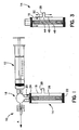
- FIG. 3 illustrates an embodiment of pressure regulating member 14 in accordance with the present invention wherein the apparatus is adapted to allow selection of a desired maximum pressure or threshold.
- cylinder 16 has a plurality of openings 44, 46 and 48, and orifice 28 is mounted on a selector member 50 which is positionable relative to openings 44, 46 and 48.
- member 50 can be positioned relative to cylinder 16 so as to align orifice 28 with a desired opening 44, 46 or 48, thereby opening and allowing flow therethrough.
- Member 50 also advantageously covers or block the other non-selected openings. As set forth above, the position of orifice 28 along the sidewall of cylinder 16 sets the maximum pressure.
- aligning orifice 28 with opening 44 would provide the lowest maximum pressure and, thereby, the most protection for a conduit or other item to which pressure is to be applied, while opening 48 when aligned with orifice 28 will allow the highest maximum pressure to be applied.
- Member 50 can advantageously be movably mounted relative to cylinder 16, for example in a track mounted on the outside of cylinder 16. Of course, other configurations can be used to positionably mount orifice 28 relative to a plurality of openings in cylinder 16.
- the apparatus of the present invention is also useful when limiting the maximum negative pressure which can be applied.
- Figures 4-6 sequentially illustrate operation of an arrangement adapted for use in such negative pressure applications.
- Figure 4 illustrates a pressure regulating member 52 which includes a housing 54 in which is mounted a slidable piston 56.
- a spring or other biasing member 58 is positioned between piston 56 and an end 60 of housing 54 within which an opening 62 is mounted and communicated with a vessel used for applying the desired negative pressure or vacuum.
- Piston 56 has several openings 64 positioned therein, and release plungers 66 slidably positioned therein.
- Application of vacuum to piston 56 serves to hold plunger 66 in position within opening 64 as desired, thereby holding the negative pressure.
- piston 56 moves toward end wall 60 as shown in Figure 5 .
- release plungers 66 have an extended body and forwardly projecting tips 68 which eventually reach and contact end wall 60 as shown in Figure 5 .
- Increase of negative pressure applied to piston 56 once piston 56 has reached this position moves piston 56 towards end wall 60 while release plungers 66 are held in place thereby allowing flow through opening 64 to release vacuum or negative pressure as desired.
- housing 52 can be open to or at least communicated with a source of substantially ambient pressure, or alternatively the space within housing 52 can be utilized as sufficient additional volume to absorb excess negative pressure being applied. Since the present invention is desired to provide an absolute maximum limit upon application of certain pressures, it is preferred for housing 52 to be communicated with a source of substantially ambient pressure.
- pressure regulating member 52 could advantageously be communicated with a device for applying negative pressure, for example through a three-way stopcock 18 as illustrated in the arrangement of Figures 1 and 2 .
- three-way stopcock would be also communicated with a source of vacuum or negative pressure, which can be in the form of a general supply of such negative pressure which is typically available in medical facilities, or a plunger adapted for pulling a negative pressure or the like.
- the present invention has provided an apparatus which can advantageously be used to limit the maximum pressure or negative pressure applied during medical procedures.
- the invention has been illustrated in the specific use of limiting pressure applied to conduits such as veins or arteries during a harvesting procedure, which is a particularly advantageous application of the apparatus in accordance with the present invention.
- the apparatus finds other useful applications within the broad scope of the present invention as well.
Landscapes
- Health & Medical Sciences (AREA)
- Surgery (AREA)
- Life Sciences & Earth Sciences (AREA)
- Molecular Biology (AREA)
- General Health & Medical Sciences (AREA)
- Oral & Maxillofacial Surgery (AREA)
- Engineering & Computer Science (AREA)
- Biomedical Technology (AREA)
- Heart & Thoracic Surgery (AREA)
- Medical Informatics (AREA)
- Nuclear Medicine, Radiotherapy & Molecular Imaging (AREA)
- Animal Behavior & Ethology (AREA)
- Pathology (AREA)
- Public Health (AREA)
- Veterinary Medicine (AREA)
- External Artificial Organs (AREA)
- Infusion, Injection, And Reservoir Apparatuses (AREA)
- Agricultural Chemicals And Associated Chemicals (AREA)
- Prostheses (AREA)
- Radiation-Therapy Devices (AREA)
Applications Claiming Priority (3)
| Application Number | Priority Date | Filing Date | Title |
|---|---|---|---|
| US43826303P | 2003-01-06 | 2003-01-06 | |
| US438263P | 2003-01-06 | ||
| PCT/US2004/000043 WO2004062473A2 (en) | 2003-01-06 | 2004-01-05 | Method and apparatus for regulating pressure during medical procedures |
Publications (3)
| Publication Number | Publication Date |
|---|---|
| EP1594390A2 EP1594390A2 (en) | 2005-11-16 |
| EP1594390A4 EP1594390A4 (en) | 2008-02-13 |
| EP1594390B1 true EP1594390B1 (en) | 2011-12-28 |
Family
ID=32713304
Family Applications (1)
| Application Number | Title | Priority Date | Filing Date |
|---|---|---|---|
| EP04700200A Expired - Lifetime EP1594390B1 (en) | 2003-01-06 | 2004-01-05 | Apparatus for regulating pressure during medical procedures |
Country Status (6)
| Country | Link |
|---|---|
| US (1) | US7998114B2 (enExample) |
| EP (1) | EP1594390B1 (enExample) |
| JP (1) | JP4722030B2 (enExample) |
| AT (1) | ATE538748T1 (enExample) |
| BR (1) | BRPI0406629A (enExample) |
| WO (1) | WO2004062473A2 (enExample) |
Families Citing this family (29)
| Publication number | Priority date | Publication date | Assignee | Title |
|---|---|---|---|---|
| SE0501889L (sv) * | 2005-08-25 | 2007-02-26 | Millicore Ab | Kärlresistansmätare |
| CA2677343C (en) | 2007-02-05 | 2016-06-21 | Boston Scientific Limited | Thrombectomy apparatus and method |
| DE102007029150A1 (de) * | 2007-06-25 | 2009-01-02 | Biotest Ag | Perfusionsvorrichtung für Hohlorgane und deren Verwendung zur Perfusion eines explantierten Hohlorgans |
| US8313467B2 (en) | 2007-12-27 | 2012-11-20 | Medtronic Minimed, Inc. | Reservoir pressure equalization systems and methods |
| US9510854B2 (en) | 2008-10-13 | 2016-12-06 | Boston Scientific Scimed, Inc. | Thrombectomy catheter with control box having pressure/vacuum valve for synchronous aspiration and fluid irrigation |
| US9320846B2 (en) * | 2012-08-28 | 2016-04-26 | Osprey Medical, Inc. | Devices and methods for modulating medium delivery |
| US10022497B2 (en) * | 2012-08-28 | 2018-07-17 | Osprey Medical, Inc. | Reservoir for collection and reuse of diverted medium |
| US20150202361A1 (en) * | 2012-08-28 | 2015-07-23 | Osprey Medical, Inc. | Devices and methods for modulating medium delivery |
| US10413677B2 (en) | 2012-08-28 | 2019-09-17 | Osprey Medical, Inc. | Volume monitoring device |
| US11219719B2 (en) | 2012-08-28 | 2022-01-11 | Osprey Medical, Inc. | Volume monitoring systems |
| US10010673B2 (en) | 2012-08-28 | 2018-07-03 | Osprey Medical, Inc. | Adjustable medium diverter |
| US11116892B2 (en) | 2012-08-28 | 2021-09-14 | Osprey Medical, Inc. | Medium injection diversion and measurement |
| EP2862592A1 (en) * | 2013-10-18 | 2015-04-22 | University of Limerick | A transurethral catheter kit, and syringe assembly suitable for use in correctly inflating a transurethral catheter |
| US9248221B2 (en) | 2014-04-08 | 2016-02-02 | Incuvate, Llc | Aspiration monitoring system and method |
| US9433427B2 (en) | 2014-04-08 | 2016-09-06 | Incuvate, Llc | Systems and methods for management of thrombosis |
| US9883877B2 (en) | 2014-05-19 | 2018-02-06 | Walk Vascular, Llc | Systems and methods for removal of blood and thrombotic material |
| EP3191153B1 (en) * | 2014-09-11 | 2019-11-06 | Osprey Medical Inc. | Reservoir for collection and reuse of diverted medium |
| US10702292B2 (en) | 2015-08-28 | 2020-07-07 | Incuvate, Llc | Aspiration monitoring system and method |
| US10561440B2 (en) | 2015-09-03 | 2020-02-18 | Vesatek, Llc | Systems and methods for manipulating medical devices |
| FR3040635B1 (fr) * | 2015-09-07 | 2017-08-25 | Commissariat Energie Atomique | Dispositif de conversion d'un liquide en vapeur |
| US20170100142A1 (en) | 2015-10-09 | 2017-04-13 | Incuvate, Llc | Systems and methods for management of thrombosis |
| US10226263B2 (en) | 2015-12-23 | 2019-03-12 | Incuvate, Llc | Aspiration monitoring system and method |
| US10492805B2 (en) | 2016-04-06 | 2019-12-03 | Walk Vascular, Llc | Systems and methods for thrombolysis and delivery of an agent |
| DE102017124927A1 (de) | 2017-10-25 | 2019-04-25 | Irasun Gmbh | System zur Vakuum-unterstützten venösen Drainage (VAVD) |
| US11678905B2 (en) | 2018-07-19 | 2023-06-20 | Walk Vascular, Llc | Systems and methods for removal of blood and thrombotic material |
| WO2020210623A1 (en) | 2019-04-12 | 2020-10-15 | Osprey Medical Inc. | Energy-efficient position determining with multiple sensors |
| US20230248367A1 (en) * | 2020-07-16 | 2023-08-10 | Prytime Medical Devices, Inc. | Inflation hub for a fluid inflatable apparatus |
| WO2022174175A1 (en) | 2021-02-15 | 2022-08-18 | Walk Vascular, Llc | Systems and methods for removal of blood and thrombotic material |
| US12274458B2 (en) | 2021-02-15 | 2025-04-15 | Walk Vascular, Llc | Systems and methods for removal of blood and thrombotic material |
Family Cites Families (19)
| Publication number | Priority date | Publication date | Assignee | Title |
|---|---|---|---|---|
| FR1435963A (fr) | 1965-03-09 | 1966-04-22 | Perfectionnements aux seringues d'injection, principalement à usage vétérinaire | |
| US3958557A (en) * | 1975-03-10 | 1976-05-25 | Texas Medical Products, Inc. | Coronary artery bypass graft testing device and method |
| US4329985A (en) | 1980-01-18 | 1982-05-18 | Shiley, Inc. | Vein distention system |
| US4323072A (en) | 1980-01-18 | 1982-04-06 | Shiley, Incorporated | Cannula for a vein distention system |
| US4403988A (en) * | 1980-08-21 | 1983-09-13 | The Kendall Company | Syringe assembly |
| DE3270633D1 (en) * | 1982-08-19 | 1986-05-22 | Vickers Systems Gmbh | Pressure-limiting apparatus |
| US4550747A (en) * | 1983-10-05 | 1985-11-05 | Digital Hydraulics, Inc. | Digital fluid pressure flow rate and position control system |
| US4623335A (en) * | 1985-10-09 | 1986-11-18 | Anthony Jackson | Apparatus and methods for detecting probe penetration of human internal target tissue having predetermined internal pressure |
| US5064193A (en) * | 1989-11-13 | 1991-11-12 | Walker Fitness Systems, Inc. | Automatic force generating and control system |
| US5250034A (en) * | 1990-09-17 | 1993-10-05 | E-Z-Em, Inc. | Pressure responsive valve catheter |
| US5591344A (en) * | 1995-02-13 | 1997-01-07 | Aksys, Ltd. | Hot water disinfection of dialysis machines, including the extracorporeal circuit thereof |
| US5558139A (en) * | 1995-02-13 | 1996-09-24 | Essex Cryogenics Of Missouri | Liquid oxygen system |
| US5568910A (en) * | 1995-03-02 | 1996-10-29 | Delmarva Laboratories, Inc. | Anesthesia machine |
| US5685851A (en) * | 1995-06-06 | 1997-11-11 | Eams Industries, Inc. | Irrigation syringe |
| US5657499A (en) * | 1996-01-11 | 1997-08-19 | Sandia Corporation | Reduced energy and volume air pump for a seat cushion |
| US5928182A (en) * | 1997-07-02 | 1999-07-27 | Johnson & Johnson Professional, Inc. | Pediatric programmable hydrocephalus valve |
| IL162731A0 (en) * | 2001-12-27 | 2005-11-20 | Playtex Products Inc | Breast pump system |
| US7641668B2 (en) * | 2003-05-16 | 2010-01-05 | Scimed Life Systems, Inc. | Fluid delivery system and related methods of use |
| US7060062B2 (en) * | 2003-06-04 | 2006-06-13 | Cryo Vascular Systems, Inc. | Controllable pressure cryogenic balloon treatment system and method |
-
2004
- 2004-01-05 JP JP2006500774A patent/JP4722030B2/ja not_active Expired - Lifetime
- 2004-01-05 EP EP04700200A patent/EP1594390B1/en not_active Expired - Lifetime
- 2004-01-05 WO PCT/US2004/000043 patent/WO2004062473A2/en not_active Ceased
- 2004-01-05 BR BR0406629-4A patent/BRPI0406629A/pt not_active IP Right Cessation
- 2004-01-05 AT AT04700200T patent/ATE538748T1/de active
- 2004-01-05 US US10/751,765 patent/US7998114B2/en not_active Expired - Lifetime
Also Published As
| Publication number | Publication date |
|---|---|
| JP4722030B2 (ja) | 2011-07-13 |
| WO2004062473A2 (en) | 2004-07-29 |
| US7998114B2 (en) | 2011-08-16 |
| JP2006526574A (ja) | 2006-11-24 |
| ATE538748T1 (de) | 2012-01-15 |
| EP1594390A4 (en) | 2008-02-13 |
| US20040138615A1 (en) | 2004-07-15 |
| WO2004062473A3 (en) | 2007-02-15 |
| EP1594390A2 (en) | 2005-11-16 |
| BRPI0406629A (pt) | 2005-12-06 |
Similar Documents
| Publication | Publication Date | Title |
|---|---|---|
| EP1594390B1 (en) | Apparatus for regulating pressure during medical procedures | |
| US12193690B1 (en) | Apparatus and methods for controlled clot aspiration | |
| CA2608633C (en) | Aspiration control | |
| US5048537A (en) | Method and apparatus for sampling blood | |
| US5423746A (en) | Method and apparatus for infiltration detection during administration of intravenous fluids | |
| JPS6458241A (en) | Assembly and method for suction of blood | |
| CA2524008A1 (en) | Arteriovenous access valve system and process | |
| US5395350A (en) | Paracentesis valve | |
| US10813667B1 (en) | Vacuum driven implantation device | |
| CN216415795U (zh) | 一种组织灌注装置 | |
| US20190328963A1 (en) | Infusion device suitable to test for extravasation | |
| US4266697A (en) | Controlled volume liquid meter defining improved plunger means | |
| WO1995021641A1 (en) | Valve apparatus | |
| US20240277352A1 (en) | Medical aspiration system | |
| US20240277353A1 (en) | Medical aspiration system | |
| US20230031759A1 (en) | Passive flow switch for medical aspiration | |
| NL2014978B1 (en) | Infusion pump unit. | |
| JP2586275B2 (ja) | 薬液注入用具 | |
| EP0358429A2 (en) | Multimodal displacement pump and dissolution system for same | |
| WO2023012665A1 (en) | Passive flow switch for medical aspiration | |
| EP4665421A1 (en) | Medical aspiration system | |
| WO2024173185A1 (en) | Medical aspiration system | |
| JP2025516901A (ja) | カテーテルの機能パラメータを決定するための方法およびカテーテル制御アセンブリ | |
| HK40050196A (en) | Apparatus and methods for controlled clot aspiration |
Legal Events
| Date | Code | Title | Description |
|---|---|---|---|
| PUAI | Public reference made under article 153(3) epc to a published international application that has entered the european phase |
Free format text: ORIGINAL CODE: 0009012 |
|
| 17P | Request for examination filed |
Effective date: 20050823 |
|
| AK | Designated contracting states |
Kind code of ref document: A2 Designated state(s): AT BE BG CH CY CZ DE DK EE ES FI FR GB GR HU IE IT LI LU MC NL PT RO SE SI SK TR |
|
| AX | Request for extension of the european patent |
Extension state: AL LT LV MK |
|
| DAX | Request for extension of the european patent (deleted) | ||
| PUAK | Availability of information related to the publication of the international search report |
Free format text: ORIGINAL CODE: 0009015 |
|
| RIC1 | Information provided on ipc code assigned before grant |
Ipc: A61B 19/00 20060101AFI20070320BHEP |
|
| A4 | Supplementary search report drawn up and despatched |
Effective date: 20080115 |
|
| 17Q | First examination report despatched |
Effective date: 20081205 |
|
| RAP1 | Party data changed (applicant data changed or rights of an application transferred) |
Owner name: MAQUET CARDIOVASCULAR LLC |
|
| RIN1 | Information on inventor provided before grant (corrected) |
Inventor name: LOMBARDI, PIERLUCA |
|
| GRAP | Despatch of communication of intention to grant a patent |
Free format text: ORIGINAL CODE: EPIDOSNIGR1 |
|
| RTI1 | Title (correction) |
Free format text: APPARATUS FOR REGULATING PRESSURE DURING MEDICAL PROCEDURES |
|
| GRAS | Grant fee paid |
Free format text: ORIGINAL CODE: EPIDOSNIGR3 |
|
| GRAA | (expected) grant |
Free format text: ORIGINAL CODE: 0009210 |
|
| AK | Designated contracting states |
Kind code of ref document: B1 Designated state(s): AT BE BG CH CY CZ DE DK EE ES FI FR GB GR HU IE IT LI LU MC NL PT RO SE SI SK TR |
|
| REG | Reference to a national code |
Ref country code: GB Ref legal event code: FG4D |
|
| REG | Reference to a national code |
Ref country code: CH Ref legal event code: EP |
|
| REG | Reference to a national code |
Ref country code: AT Ref legal event code: REF Ref document number: 538748 Country of ref document: AT Kind code of ref document: T Effective date: 20120115 |
|
| REG | Reference to a national code |
Ref country code: IE Ref legal event code: FG4D |
|
| REG | Reference to a national code |
Ref country code: DE Ref legal event code: R096 Ref document number: 602004035853 Country of ref document: DE Effective date: 20120308 |
|
| REG | Reference to a national code |
Ref country code: NL Ref legal event code: VDEP Effective date: 20111228 |
|
| PG25 | Lapsed in a contracting state [announced via postgrant information from national office to epo] |
Ref country code: GR Free format text: LAPSE BECAUSE OF FAILURE TO SUBMIT A TRANSLATION OF THE DESCRIPTION OR TO PAY THE FEE WITHIN THE PRESCRIBED TIME-LIMIT Effective date: 20120329 Ref country code: SI Free format text: LAPSE BECAUSE OF FAILURE TO SUBMIT A TRANSLATION OF THE DESCRIPTION OR TO PAY THE FEE WITHIN THE PRESCRIBED TIME-LIMIT Effective date: 20111228 Ref country code: SE Free format text: LAPSE BECAUSE OF FAILURE TO SUBMIT A TRANSLATION OF THE DESCRIPTION OR TO PAY THE FEE WITHIN THE PRESCRIBED TIME-LIMIT Effective date: 20111228 |
|
| PG25 | Lapsed in a contracting state [announced via postgrant information from national office to epo] |
Ref country code: BE Free format text: LAPSE BECAUSE OF FAILURE TO SUBMIT A TRANSLATION OF THE DESCRIPTION OR TO PAY THE FEE WITHIN THE PRESCRIBED TIME-LIMIT Effective date: 20111228 Ref country code: CY Free format text: LAPSE BECAUSE OF FAILURE TO SUBMIT A TRANSLATION OF THE DESCRIPTION OR TO PAY THE FEE WITHIN THE PRESCRIBED TIME-LIMIT Effective date: 20111228 |
|
| PG25 | Lapsed in a contracting state [announced via postgrant information from national office to epo] |
Ref country code: CZ Free format text: LAPSE BECAUSE OF FAILURE TO SUBMIT A TRANSLATION OF THE DESCRIPTION OR TO PAY THE FEE WITHIN THE PRESCRIBED TIME-LIMIT Effective date: 20111228 Ref country code: NL Free format text: LAPSE BECAUSE OF FAILURE TO SUBMIT A TRANSLATION OF THE DESCRIPTION OR TO PAY THE FEE WITHIN THE PRESCRIBED TIME-LIMIT Effective date: 20111228 Ref country code: EE Free format text: LAPSE BECAUSE OF FAILURE TO SUBMIT A TRANSLATION OF THE DESCRIPTION OR TO PAY THE FEE WITHIN THE PRESCRIBED TIME-LIMIT Effective date: 20111228 Ref country code: BG Free format text: LAPSE BECAUSE OF FAILURE TO SUBMIT A TRANSLATION OF THE DESCRIPTION OR TO PAY THE FEE WITHIN THE PRESCRIBED TIME-LIMIT Effective date: 20120328 Ref country code: SK Free format text: LAPSE BECAUSE OF FAILURE TO SUBMIT A TRANSLATION OF THE DESCRIPTION OR TO PAY THE FEE WITHIN THE PRESCRIBED TIME-LIMIT Effective date: 20111228 |
|
| PG25 | Lapsed in a contracting state [announced via postgrant information from national office to epo] |
Ref country code: MC Free format text: LAPSE BECAUSE OF NON-PAYMENT OF DUE FEES Effective date: 20120131 Ref country code: RO Free format text: LAPSE BECAUSE OF FAILURE TO SUBMIT A TRANSLATION OF THE DESCRIPTION OR TO PAY THE FEE WITHIN THE PRESCRIBED TIME-LIMIT Effective date: 20111228 Ref country code: PT Free format text: LAPSE BECAUSE OF FAILURE TO SUBMIT A TRANSLATION OF THE DESCRIPTION OR TO PAY THE FEE WITHIN THE PRESCRIBED TIME-LIMIT Effective date: 20120430 |
|
| REG | Reference to a national code |
Ref country code: CH Ref legal event code: PL |
|
| REG | Reference to a national code |
Ref country code: AT Ref legal event code: MK05 Ref document number: 538748 Country of ref document: AT Kind code of ref document: T Effective date: 20111228 |
|
| REG | Reference to a national code |
Ref country code: IE Ref legal event code: MM4A |
|
| PG25 | Lapsed in a contracting state [announced via postgrant information from national office to epo] |
Ref country code: LI Free format text: LAPSE BECAUSE OF NON-PAYMENT OF DUE FEES Effective date: 20120131 Ref country code: CH Free format text: LAPSE BECAUSE OF NON-PAYMENT OF DUE FEES Effective date: 20120131 Ref country code: DK Free format text: LAPSE BECAUSE OF FAILURE TO SUBMIT A TRANSLATION OF THE DESCRIPTION OR TO PAY THE FEE WITHIN THE PRESCRIBED TIME-LIMIT Effective date: 20111228 |
|
| PLBE | No opposition filed within time limit |
Free format text: ORIGINAL CODE: 0009261 |
|
| STAA | Information on the status of an ep patent application or granted ep patent |
Free format text: STATUS: NO OPPOSITION FILED WITHIN TIME LIMIT |
|
| PG25 | Lapsed in a contracting state [announced via postgrant information from national office to epo] |
Ref country code: IT Free format text: LAPSE BECAUSE OF FAILURE TO SUBMIT A TRANSLATION OF THE DESCRIPTION OR TO PAY THE FEE WITHIN THE PRESCRIBED TIME-LIMIT Effective date: 20111228 |
|
| 26N | No opposition filed |
Effective date: 20121001 |
|
| REG | Reference to a national code |
Ref country code: DE Ref legal event code: R097 Ref document number: 602004035853 Country of ref document: DE Effective date: 20121001 |
|
| PG25 | Lapsed in a contracting state [announced via postgrant information from national office to epo] |
Ref country code: IE Free format text: LAPSE BECAUSE OF NON-PAYMENT OF DUE FEES Effective date: 20120105 Ref country code: AT Free format text: LAPSE BECAUSE OF FAILURE TO SUBMIT A TRANSLATION OF THE DESCRIPTION OR TO PAY THE FEE WITHIN THE PRESCRIBED TIME-LIMIT Effective date: 20111228 |
|
| PG25 | Lapsed in a contracting state [announced via postgrant information from national office to epo] |
Ref country code: ES Free format text: LAPSE BECAUSE OF FAILURE TO SUBMIT A TRANSLATION OF THE DESCRIPTION OR TO PAY THE FEE WITHIN THE PRESCRIBED TIME-LIMIT Effective date: 20120408 |
|
| PG25 | Lapsed in a contracting state [announced via postgrant information from national office to epo] |
Ref country code: FI Free format text: LAPSE BECAUSE OF FAILURE TO SUBMIT A TRANSLATION OF THE DESCRIPTION OR TO PAY THE FEE WITHIN THE PRESCRIBED TIME-LIMIT Effective date: 20111228 |
|
| PG25 | Lapsed in a contracting state [announced via postgrant information from national office to epo] |
Ref country code: TR Free format text: LAPSE BECAUSE OF FAILURE TO SUBMIT A TRANSLATION OF THE DESCRIPTION OR TO PAY THE FEE WITHIN THE PRESCRIBED TIME-LIMIT Effective date: 20111228 |
|
| PG25 | Lapsed in a contracting state [announced via postgrant information from national office to epo] |
Ref country code: LU Free format text: LAPSE BECAUSE OF NON-PAYMENT OF DUE FEES Effective date: 20120105 |
|
| PG25 | Lapsed in a contracting state [announced via postgrant information from national office to epo] |
Ref country code: HU Free format text: LAPSE BECAUSE OF FAILURE TO SUBMIT A TRANSLATION OF THE DESCRIPTION OR TO PAY THE FEE WITHIN THE PRESCRIBED TIME-LIMIT Effective date: 20040105 |
|
| REG | Reference to a national code |
Ref country code: FR Ref legal event code: PLFP Year of fee payment: 13 |
|
| REG | Reference to a national code |
Ref country code: FR Ref legal event code: PLFP Year of fee payment: 14 |
|
| REG | Reference to a national code |
Ref country code: FR Ref legal event code: PLFP Year of fee payment: 15 |
|
| PGFP | Annual fee paid to national office [announced via postgrant information from national office to epo] |
Ref country code: FR Payment date: 20230320 Year of fee payment: 20 |
|
| PGFP | Annual fee paid to national office [announced via postgrant information from national office to epo] |
Ref country code: GB Payment date: 20230315 Year of fee payment: 20 |
|
| PGFP | Annual fee paid to national office [announced via postgrant information from national office to epo] |
Ref country code: DE Payment date: 20230412 Year of fee payment: 20 |
|
| REG | Reference to a national code |
Ref country code: DE Ref legal event code: R071 Ref document number: 602004035853 Country of ref document: DE |
|
| REG | Reference to a national code |
Ref country code: GB Ref legal event code: PE20 Expiry date: 20240104 |
|
| PG25 | Lapsed in a contracting state [announced via postgrant information from national office to epo] |
Ref country code: GB Free format text: LAPSE BECAUSE OF EXPIRATION OF PROTECTION Effective date: 20240104 |