EP1594123A2 - Verfahren zum Erhalt der Integrität von Spuren in magnetischen Plattenspeichereinheiten - Google Patents
Verfahren zum Erhalt der Integrität von Spuren in magnetischen Plattenspeichereinheiten Download PDFInfo
- Publication number
- EP1594123A2 EP1594123A2 EP05252837A EP05252837A EP1594123A2 EP 1594123 A2 EP1594123 A2 EP 1594123A2 EP 05252837 A EP05252837 A EP 05252837A EP 05252837 A EP05252837 A EP 05252837A EP 1594123 A2 EP1594123 A2 EP 1594123A2
- Authority
- EP
- European Patent Office
- Prior art keywords
- data
- implemented
- storage
- detector
- track
- Prior art date
- Legal status (The legal status is an assumption and is not a legal conclusion. Google has not performed a legal analysis and makes no representation as to the accuracy of the status listed.)
- Ceased
Links
Images


Classifications
-
- G—PHYSICS
- G11—INFORMATION STORAGE
- G11B—INFORMATION STORAGE BASED ON RELATIVE MOVEMENT BETWEEN RECORD CARRIER AND TRANSDUCER
- G11B19/00—Driving, starting, stopping record carriers not specifically of filamentary or web form, or of supports therefor; Control thereof; Control of operating function ; Driving both disc and head
- G11B19/02—Control of operating function, e.g. switching from recording to reproducing
- G11B19/04—Arrangements for preventing, inhibiting, or warning against double recording on the same blank or against other recording or reproducing malfunctions
- G11B19/041—Detection or prevention of read or write errors
- G11B19/045—Detection or prevention of read or write errors by detecting mistracking
-
- G—PHYSICS
- G11—INFORMATION STORAGE
- G11B—INFORMATION STORAGE BASED ON RELATIVE MOVEMENT BETWEEN RECORD CARRIER AND TRANSDUCER
- G11B20/00—Signal processing not specific to the method of recording or reproducing; Circuits therefor
- G11B20/10—Digital recording or reproducing
- G11B20/18—Error detection or correction; Testing, e.g. of drop-outs
- G11B20/1883—Methods for assignment of alternate areas for defective areas
-
- G—PHYSICS
- G11—INFORMATION STORAGE
- G11B—INFORMATION STORAGE BASED ON RELATIVE MOVEMENT BETWEEN RECORD CARRIER AND TRANSDUCER
- G11B5/00—Recording by magnetisation or demagnetisation of a record carrier; Reproducing by magnetic means; Record carriers therefor
- G11B5/02—Recording, reproducing, or erasing methods; Read, write or erase circuits therefor
- G11B5/09—Digital recording
-
- G—PHYSICS
- G11—INFORMATION STORAGE
- G11B—INFORMATION STORAGE BASED ON RELATIVE MOVEMENT BETWEEN RECORD CARRIER AND TRANSDUCER
- G11B20/00—Signal processing not specific to the method of recording or reproducing; Circuits therefor
- G11B20/10—Digital recording or reproducing
- G11B20/18—Error detection or correction; Testing, e.g. of drop-outs
- G11B20/1816—Testing
- G11B2020/183—Testing wherein at least one additional attempt is made to read or write the data when a first attempt is unsuccessful
Definitions
- Track squeeze is seen especially in very high data density devices, when they are used under high loads in server applications. It appears when a track on the disk drive is written only rarely, while one or both of the adjacent tracks are written much more frequently. Due to the finite positioning tolerance of the head actuator mechanism, the electromagnetic forces used to effect adj acent track writes intrude to some extent into the rarely written track, causing reduced signal strength of the affected track. This in turn causes data errors during read operations. This problem can be reduced or avoided by reducing the track density on the disk surface or increasing the sophistication and accuracy of the head actuator and the data read process, but all of these techniques have associated cost.
- the present invention is directed to techniques that detect impending data errors such as the track squeeze problem, and, furthermore, to repair the problem or impending problem when detected, such as by rewriting the affected tracks.
- impending data errors such as the track squeeze problem
- repair is effected when the original data can still be read. As a result, that original data is used directly to do the repair.
- the data is no longer readable on the disk in question, but when the disk is part of a RAID system, or other system in which higher level, system fault tolerance mechanisms are implemented, the missing data can be recovered via RAID layer mechanisms and then used to repair the track squeeze problem.
- the invention can be implemented as firmware in a storage system, as a component of a general purpose operating system, or inside individual disk drives, or it can use a combination of these implementations.
- the invention can also be implemented as part of a functioning system in use by a customer in the field, in a manufacturing screening process, or in a diagnosis and repair of units returned from the field.
- the present invention offers a number of advantages over the prior art.
- the invention By detecting errors such as track squeeze usually before the point where they are severe enough to cause unrecoverable data loss, the invention protects customer data from these errors. And by corrective action that actually repairs the underlying problem, the invention effectively eliminates errors such as track squeeze from being a factor in limiting the useful life of disk drives or a factor in the failure rate of disk drives in the field. Repairing the underlying problem also repairs the performance loss that appears when the errors are still recoverable by normal disk drive recovery mechanisms such as ECC or read retry.
- the invention relies only on properties of conventional industry standard disk drives. It does not require any specialized error indications, counters, or non-standard drive commands. Furthermore, the invention comprises both detection and repair, after which the impending problem is eliminated. It is not merely an enhanced read error retry scheme - which might delay the point at which gradual onset errors become unrecoverable, and which does not correct the underlying problem.
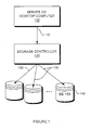
- Figure 1 shows a computer system, which may be a server system or a user workstation such as a desktop or laptop computer.
- the host or base computer 100 (the central processor of the computer system excluding its attached storage), connects to a storage controller 120.
- the storage controller 120 may be a simple disk controller, or it may incorporate more advanced storage mechanisms such as Redundant Array of Independent Disks (RAID).
- the computer 100 is connected to the controller 120 via an interconnect 110.
- the interconnect may be a system bus such as the Peripheral Component Interface (PCI) bus, or it may be a Storage Area Network (SAN) based on Fibre Channel or other SAN technology.
- the storage controller 120 in turns connects to one or more disk drives 140, via disk channels 130.
- the disk channels may be provided any suitable disk drive interface such as Advanced Technology Attachment (ATA), Small Computer System Interface (SCSI) or other disk interfaces.
- ATA Advanced Technology Attachment
- SCSI Small Computer System Interface
- the processes described below may be implemented in computer 100, in storage controller 120, or within drive electronics 150 contained in the disk drives 140.
- the implementation would be part of the operating system or device drivers installed in that computer.
- the recovery process described in Figure 7 may be used, if the computer or storage controller includes higher system layer functions, such as a RAID fault tolerance mechanism, data mirroring, or backup.
- the recovery process described in Figure 6 would be applied, unless provision is made to communicate with any higher layer fault tolerance mechanisms implemented elsewhere, e.g., in storage controller 120.
- the processes described below might be implemented in part in one component and in part in another.
- the detection processes described in Figures 2 through 5 might be implemented in disk drives 140, while the recovery mechanism described in Figure 7 is implemented in storage controller 120.
- FIGS 2 through 5 shows flow charts for four different variations for processes that detect impending data integrity errors (impending data loss).
- the process shown performs the actual I/O operations requested by other components of the system, along with detection steps that serve to detect impending data errors.
- the intent of these steps is to be able, in many cases, to indicate that data loss is threatened before such loss actually occurs. As a result, the threatened data is typically still readable, and this data is available for the repair process.
- Several of the variations shown here rely on a common characteristic of the class of errors to be detected, namely that the early stages of gradual onset errors such as track squeeze are recoverable by the disk drive using its normal error recovery mechanism, but these mechanisms take time and are therefore detectable by observing the drive performance. It should be noted that these approaches are applicable to all disk drives, and are not dependent on any unusual or customized error reporting capabilities in the disk drives.
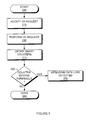
- FIG. 2 illustrates an impending data error detection process that uses I/O timing variance for its detection mechanism.
- the process begins at step 210 by accepting an I/O request, such as a data read or data write operation, from other components of the system.
- an I/O request such as a data read or data write operation
- the current time is recorded.
- the I/O request is performed in the usual manner, such as by sending an I/O command to the disk drive, which in turn causes a data read or write operation to occur from or to the magnetic media on the disk, such as via a read/record head.
- the elapsed time required to perform the I/O is computed.
- step 250 computed elapsed time values from a number of consecutive I/O requests are analyzed statistically to compute the variance of the elapsed time.
- step 260 the calculated variance is compared with a threshold setting to determine if it exceeds the expected variance.
- the expected variance can be established from data provided by the disk drive manufacturer, or from measurements made as part of product design or disk drive type acceptance.
- step 270 if the observed variance exceeds the established threshold value, the process indicates that impending data loss has been detected. In either case, the I/O operation is now complete.
- FIG. 3 illustrates an impending data error detection process that uses disk drive SMART (Self-Monitoring, Analysis, and Reporting Technology) counters for its detection mechanism.
- SMART Self-Monitoring, Analysis, and Reporting Technology
- the process begins at step 210 by accepting an I/O request from other components of the system.
- the I/O request is performed in the usual manner.
- the SMART counters are obtained.
- appropriate SMART counters such as the Raw Read Error Rate counter, are compared with a threshold setting.
- the threshold setting is typically chosen by design and may be supplied by the manufacturer of the disk drive.
- the process indicates that impending data loss has been detected. In either case, the I/O operation is now complete.
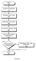
- Figure 4 illustrates an impending data error detection process that uses deviation from expected throughput for its detection mechanism.
- the process begins at step 210 by accepting an I/O request from other components of the system.
- the current time is recorded.
- the I/O request is performed in the usual manner.
- the elapsed time required to perform the I/O is computed.
- computed elapsed time values from a number of consecutive I/O requests for a given disk drive track or portion of a track are analyzed statistically to compute the average I/O throughput.
- the calculated throughput is compared with a threshold setting to determine if it exceeds the expected variance.
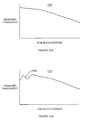
- the expected throughput can be established from data provided by the disk drive manufacturer, or from measurements made as part of product design or disk drive type acceptance; this is described further below in Figures 12A and 12B.
- the process indicates that impending data loss has been detected for the track or portion of the track in question. In either case, the I/O operation is now complete.
- FIG. 5 illustrates an impending data error detection process that uses I/O timing and I/O operation timeout for its detection mechanism.
- the process begins at step 210 by accepting an I/O request from other components of the system.
- the current time is recorded.
- the I/O request is performed in the usual manner.
- the elapsed time required to perform the I/O is computed.
- the elapsed is compared with a threshold setting to determine if it exceeds the expected time required to perform an I/O operation, or if the I/O operation timed out.
- the expected I/O latency can be established from data provided by the disk drive manufacturer, or from measurements made as part of product design or disk drive type acceptance.
- the process indicates that impending data loss has been detected. In either case, the I/O operation is now complete.
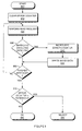
- FIGS 6 and 7 are flow charts for processes that respond to an indication of impending data loss by taking corrective action.
- the corrective action has the effect of completely repairing the impending error; that is, the operation of the disk (for that track or portion of the track) is restored to full normal operation at normal performance.
- the normal disk drive recovery mechanisms triggered by the gradual onset error have a cost in I/O performance; the repair process, by eliminating the error, restores the drive to its full performance.
- the corrective action appropriate for the "track squeeze" error is rewriting of the affected tracks or portion of a track. A single rewrite operation suffices for current generation disk drives.
- the processes described here are not limited to a single rewrite operation, and other recovery mechanisms (for example, multiple rewrite operations) may be employed if the disk drive technology changes to make such changes necessary. Furthermore, the recovery process may rewrite a region larger than a single track. This effectively handles cases where track squeeze occurs on several adjacent tracks, or when the disk access patterns are such that detectable track squeeze on one track is an indication that track squeeze is likely to be a near-term risk on other tracks in the region.
- the correction process starts by performing an I/O request 610 according to any of the processes shown above in Figures 2 through 5.
- step 620 the process checks whether the I/O operation process 610 indicated that impending data loss was detected. If not, the I/O operation is complete. If impending data loss was detected, step 630 then determines whether the I/O operation was a read operation and that operation successfully read the data requested. If not (i.e., either the operation was not a read, or it was not successful), at step 640 the process performs a read operation.
- This read operation 640 may include more extensive than normal error recovery mechanisms, for example the use of longer than normal timeouts, to maximize the probability that the data can be read from the disk drive.
- step 650 the process checks if that read operation succeeded; if not, the I/O operation is unsuccessful and no corrective action is possible, at step 660. If data was read successfully either via step 630 or step 650, the data obtained is written back to the disk at step 670. At this point, the I/O operation is complete and successful.
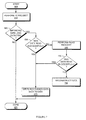
- Figure 7 illustrates an I/O process incorporated in a storage system that includes data recovery mechanisms beyond that which can be performed by the disk drives 140 themselves.
- data recovery mechanisms may include RAID, or other mechanisms such as data replication or data backup. They may also include mechanisms that can reconstruct the needed data on demand from information maintained in higher layer memory data, for example RAID metadata, or control structures in a file system or storage virtualization (logical volume manager) system.
- the process starts by performing an I/O request 610 according to any of the processes shown above in Figures 2 through 5.
- step 620 the process checks whether the I/O operation process 610 indicated that impending data loss was detected. If not, the I/O operation is complete.
- step 630 determines whether the I/O operation was a read operation and that operation successfully read the data requested. If not (i.e., either the operation was not a read, or it was not successful), at step 640 the process performs a read operation. This read operation 640 may include more extensive than normal error recovery mechanisms, for example the use of longer than normal timeouts, to maximize the probability that the data can be read from the disk drive.
- the process checks if that read operation succeeded. If not, at step 700 the process uses the available higher layer data recovery mechanisms (such as RAID) to reconstruct the data that could not be read from the disk drive. The data obtained either by successful read operations at step 630 or 650, or by the higher layer data reconstruction step 700, is then written back to the disk at step 710. At this point, the I/O operation is complete and successful.
- Figure 8 is a flow chart for a device acceptance or fault analysis process.
- the illustrated process could be one of the steps in an incoming disk drive screening process used in a manufacturing line. It can also be used as a step in a fault analysis process applied to disk drives suspected to be defective.
- the process begins at step 810 by initializing an error counter.
- a read request is performed according to any of the processes described in Figures 2 through 5.
- the process tests whether the read process 820 reported impending data loss. If yes, at step 840 the error counter is incremented, and at step 850 known good data is written to repair the impending error.
- Step 860 tests whether the disk scan is complete, and if not, the process repeats steps 820 through 850 as required to scan the disk drive thoroughly.
- the error counter is compared with a threshold value. The threshold value is set by design or engineering policy, based on a determination of what level of impending data loss indication is considered acceptable and normal in the current generation of disk drives. If the error counter exceeds the established threshold, the disk drive is rejected at step 890; otherwise it is accepted at step 880.
- Figures 9 through 11 illustrate how the processes described above may be incorporated into the layered structure of an operating system storage subsystem, storage controller, or disk drive I/O processing subsystem.
- the detection and recovery processes are incorporated in the processing path that processes I/O requests from the users or application programs that use the storage device. These I/O requests are represented schematically by arrow 900. These I/O requests may be submitted, for example, via operating system request mechanisms, or via messages delivered across a system bus or SAN.
- the lowest processing layer 930 is the conventional I/O processing layer, for example a device driver. Layered above that layer 930 is impending error detection layer 920, which implements any of the processes shown in Figures 2 through 5. Layered above that is an error recovery layer 910, which implements the process described in Figure 6 (or possibly that described in Figure 7).
- the detection and recovery processes are used by a disk surface scan process 1000.
- This approach is useful when it is desirable to scan the entire surface of the disk drive (or all disk drives) for gradual onset errors, rather than only rely on detecting such impending errors when the affected area is actually referenced by users or application programs.
- both approaches may be combined within a single system, i.e., both the methods of figure 9 and the method of figure 10 may exist in a system at the same time. This provides both real-time recovery from errors detected during user I/O handling, and background scanning for errors on the entire disk or disk array.
- the lowest processing layer 930 is the conventional I/O processing layer, for example a device driver. Layered above that layer 930 is impending error detection layer 920, which implements any of the processes described in Figures 2 through 5. Layered above that layer 920 is error recovery layer 910, which implements the process described in Figure 6 (or possibly that described in Figure 7).
- Figure 11 illustrates an example of the detection and recovery processes incorporated in a storage system that implements RAID.
- the lowest processing layer 930 is the conventional I/O processing layer, for example a device driver.
- impending error detection layer 920 which implements any of the processes described in Figures 2 through 5.
- RAID subsystem 1100 Layered above that layer 920 is RAID subsystem 1100.
- recovery process 1110 Contained within the RAID subsystem is recovery process 1110, which implements the process described in Figure 7.
- the recovery process cannot recover data from an individual disk drive, it employs the higher layer redundancy mechanisms of RAID to reconstruct the lost data, which it then uses to correct the error as shown in Figure 7, at steps 700 and 710.
- Figures 12A-12B illustrate that measured I/O throughput is dependent on disk block address, and shows an example of throughput affected by errors such as track squeeze.
- Graph 1200 is a typical example of measured I/O throughput for a fully functional drive.
- the graph shows disk block address on the X-axis vs. throughput on the Y-axis.
- throughput is not constant for all blocks; instead it varies in a fairly smooth fashion according to block address.
- the underlying reason for this is that in modem disk drives the number of blocks per track (i.e., per disk revolution) changes according to the circumference of the track, so lower block numbers, which are closer to the outer (longer) tracks, correspond to more sectors accessed per disk revolution.
- the expected throughput graph 1200 is fixed, and can be learned from data provided by the drive manufacturer or measured during system design or as part of drive type acceptance.
- Graph 1210 shows an example of the change in I/O throughput caused by gradual onset errors such as track squeeze.
- region 1220 of the graph shows lower than expected throughput and deviates significantly from the corresponding region of the normal smooth graph 1200. This deviation, when it exceeds a threshold set by design, is used in the process described in Figure 4 as indication of impending data loss.
Landscapes
- Engineering & Computer Science (AREA)
- Signal Processing (AREA)
- Debugging And Monitoring (AREA)
- Signal Processing For Digital Recording And Reproducing (AREA)
Applications Claiming Priority (2)
| Application Number | Priority Date | Filing Date | Title |
|---|---|---|---|
| US10/841,258 US7475276B2 (en) | 2004-05-07 | 2004-05-07 | Method for maintaining track data integrity in magnetic disk storage devices |
| US841258 | 2004-05-07 |
Publications (2)
| Publication Number | Publication Date |
|---|---|
| EP1594123A2 true EP1594123A2 (de) | 2005-11-09 |
| EP1594123A3 EP1594123A3 (de) | 2007-08-29 |
Family
ID=34941208
Family Applications (1)
| Application Number | Title | Priority Date | Filing Date |
|---|---|---|---|
| EP05252837A Ceased EP1594123A3 (de) | 2004-05-07 | 2005-05-09 | Verfahren zum Erhalt der Integrität von Spuren in magnetischen Plattenspeichereinheiten |
Country Status (3)
| Country | Link |
|---|---|
| US (2) | US7475276B2 (de) |
| EP (1) | EP1594123A3 (de) |
| JP (1) | JP5078235B2 (de) |
Cited By (2)
| Publication number | Priority date | Publication date | Assignee | Title |
|---|---|---|---|---|
| EP2778926A1 (de) * | 2012-04-28 | 2014-09-17 | Huawei Technologies Co., Ltd. | Verfahren, vorrichtung und system zur wiederherstellung von festplattendaten |
| CN106648948A (zh) * | 2016-12-28 | 2017-05-10 | 四川秘无痕信息安全技术有限责任公司 | 一种针对西数硬盘11号模块损坏的修复方法 |
Families Citing this family (21)
| Publication number | Priority date | Publication date | Assignee | Title |
|---|---|---|---|---|
| US7490270B2 (en) * | 2004-11-09 | 2009-02-10 | Dell Products L.P. | Method, system, and software for rebuilding a storage drive |
| JP2007242207A (ja) * | 2006-03-13 | 2007-09-20 | Fujitsu Ltd | ディスク装置の媒体スキャン方法 |
| US20070294588A1 (en) * | 2006-05-09 | 2007-12-20 | Coulson Richard L | Performing a diagnostic on a block of memory associated with a correctable read error |
| JP2008010113A (ja) * | 2006-06-30 | 2008-01-17 | Fujitsu Ltd | 磁気ディスク制御装置、磁気ディスク装置および読取り障害修復方法 |
| US7522366B2 (en) | 2006-11-30 | 2009-04-21 | Lenovo (Singapore) Pte. Ltd. | Preservation of hard drive data via preliminary detection of adjacent track interference potential |
| US7774539B2 (en) | 2007-02-07 | 2010-08-10 | Lenovo (Singapore) Pte. Ltd | Preservation of hard drive data via dynamic band boundary definition |
| JP4456626B2 (ja) * | 2007-09-28 | 2010-04-28 | 富士通株式会社 | ディスクアレイ装置、ディスクアレイ装置制御プログラムおよびディスクアレイ装置制御方法 |
| US8176149B2 (en) * | 2008-06-30 | 2012-05-08 | International Business Machines Corporation | Ejection of storage drives in a computing network |
| US8867161B2 (en) | 2013-03-15 | 2014-10-21 | Seagate Technology Llc | Shingled magnetic recording with variable track spacing |
| JP6155768B2 (ja) | 2013-03-29 | 2017-07-05 | 富士通株式会社 | ストレージ制御装置、ストレージ制御プログラム及びストレージ制御方法 |
| EP3022736A1 (de) | 2013-07-15 | 2016-05-25 | Hewlett Packard Enterprise Development LP | Wiederaufbau von laufwerkdaten |
| US9594698B2 (en) | 2013-08-13 | 2017-03-14 | Dell Products, Lp | Local keying for self-encrypting drives (SED) |
| US10013280B2 (en) * | 2013-09-30 | 2018-07-03 | Dell Products, Lp | System and method for host-assisted background media scan (BMS) |
| JP6252285B2 (ja) | 2014-03-24 | 2017-12-27 | 富士通株式会社 | ストレージ制御装置、制御方法、及びプログラム |
| US10339079B2 (en) | 2014-06-02 | 2019-07-02 | Western Digital Technologies, Inc. | System and method of interleaving data retrieved from first and second buffers |
| US9117463B1 (en) | 2014-06-23 | 2015-08-25 | Western Digital Technologies, Inc. | Data storage device erasing multiple adjacent data tracks to recover from inter-track interference |
| US9367254B2 (en) | 2014-06-27 | 2016-06-14 | HGST Netherlands B.V. | Enhanced data verify in data storage arrays |
| JP2017062715A (ja) * | 2015-09-25 | 2017-03-30 | 富士通株式会社 | ストレージ装置、制御ユニット、及び制御プログラム |
| US9607633B1 (en) | 2016-04-06 | 2017-03-28 | Seagate Technology Llc | Shingled magnetic recording interband track pitch tuning |
| US11023605B1 (en) * | 2017-04-20 | 2021-06-01 | EMC IP Holding Company LLC | Data access threat detection and prevention |
| US10418062B2 (en) * | 2017-12-19 | 2019-09-17 | International Business Machines Corporation | Efficient rewrite using larger codeword sizes |
Citations (3)
| Publication number | Priority date | Publication date | Assignee | Title |
|---|---|---|---|---|
| US4516165A (en) * | 1982-12-27 | 1985-05-07 | International Business Machines Corporation | Error recovery procedure using selective erasure |
| US5166936A (en) | 1990-07-20 | 1992-11-24 | Compaq Computer Corporation | Automatic hard disk bad sector remapping |
| US5379162A (en) | 1993-08-19 | 1995-01-03 | International Business Machines Corporation | Customized data recovery procedures selected responsive to readback errors and transducer head and disk parameters |
Family Cites Families (21)
| Publication number | Priority date | Publication date | Assignee | Title |
|---|---|---|---|---|
| US257617A (en) * | 1882-05-09 | Dredging-machine | ||
| US5974544A (en) | 1991-12-17 | 1999-10-26 | Dell Usa, L.P. | Method and controller for defect tracking in a redundant array |
| JPH05257617A (ja) | 1992-03-12 | 1993-10-08 | Nec Corp | 磁気ディスクサブシステム |
| KR100208383B1 (ko) * | 1997-06-03 | 1999-07-15 | 윤종용 | 하드 디스크 드라이브의 용량변환 생산방법 |
| JP3184171B2 (ja) * | 1998-02-26 | 2001-07-09 | 日本電気株式会社 | ディスクアレイ装置、そのエラー制御方法、ならびにその制御プログラムを記録した記録媒体 |
| JPH11306695A (ja) | 1998-04-27 | 1999-11-05 | Mitsumi Electric Co Ltd | 磁気記録媒体のディフェクト管理方法、およびその方法を実現するプログラムを記録した記録媒体 |
| US6405277B1 (en) | 1998-11-06 | 2002-06-11 | International Business Machines Corporation | Method and system for writing data to a magnetic storage device in a relatively cold or hot environment |
| US6442705B1 (en) | 1999-04-26 | 2002-08-27 | International Business Machines Corporation | Method of and apparatus for improving data integrity in a disk drive system |
| JP2000311452A (ja) * | 1999-04-28 | 2000-11-07 | Nec Corp | 磁気ディスク装置 |
| JP2000322334A (ja) | 1999-05-13 | 2000-11-24 | Nec Soft Ltd | 入出力自動性能監視システム |
| US6710952B1 (en) * | 2000-01-19 | 2004-03-23 | Hitachi Global Storage Technologies Netherlands, B.V. | System and method for gracefully relinquishing a computer hard disk drive from imminent catastrophic failure |
| US6384599B1 (en) * | 2000-02-01 | 2002-05-07 | International Business Machines Corporation | System, method, and program for analyzing offset track errors in a storage system |
| US6628471B1 (en) * | 2000-06-16 | 2003-09-30 | Seagate Technology Llc | Detection and cancellation of cage frequency using the clock head in a servowriter |
| US6882489B1 (en) * | 2000-08-15 | 2005-04-19 | Maxtor Corporation | Dynamic off-track detector |
| US6785084B2 (en) * | 2000-10-24 | 2004-08-31 | Seagate Technology Llc | Correction of dynamic track spacing errors in storage devices |
| JP2004063013A (ja) * | 2002-07-30 | 2004-02-26 | Matsushita Electric Ind Co Ltd | Av性能検査方法とそれを用いた磁気ディスク装置の製造方法および磁気ディスク装置 |
| JP2004110946A (ja) * | 2002-09-19 | 2004-04-08 | Hitachi Ltd | 磁気ディスク装置 |
| JP4063694B2 (ja) * | 2003-03-11 | 2008-03-19 | 株式会社日立グローバルストレージテクノロジーズ | 磁気ディスク装置 |
| SG118195A1 (en) * | 2003-07-10 | 2006-01-27 | Agency Science Tech & Res | Detection of track misregistration within user data channel |
| JP2005116096A (ja) | 2003-10-09 | 2005-04-28 | Toshiba Corp | ディスク記憶装置及びサーボ書込み方法 |
| US7650686B2 (en) | 2007-12-28 | 2010-01-26 | Hitachi Global Storage Technologies Netherlands B.V. | Servo track writer clockhead radius jig |
-
2004
- 2004-05-07 US US10/841,258 patent/US7475276B2/en active Active
-
2005
- 2005-05-06 JP JP2005134986A patent/JP5078235B2/ja active Active
- 2005-05-09 EP EP05252837A patent/EP1594123A3/de not_active Ceased
-
2008
- 2008-09-17 US US12/284,021 patent/US8190945B2/en not_active Expired - Lifetime
Patent Citations (3)
| Publication number | Priority date | Publication date | Assignee | Title |
|---|---|---|---|---|
| US4516165A (en) * | 1982-12-27 | 1985-05-07 | International Business Machines Corporation | Error recovery procedure using selective erasure |
| US5166936A (en) | 1990-07-20 | 1992-11-24 | Compaq Computer Corporation | Automatic hard disk bad sector remapping |
| US5379162A (en) | 1993-08-19 | 1995-01-03 | International Business Machines Corporation | Customized data recovery procedures selected responsive to readback errors and transducer head and disk parameters |
Non-Patent Citations (2)
| Title |
|---|
| "Prevention of Hard Errors in magnetic Files Due to Long Term Degradation", IBM TECHNICAL DISCLOSURE BULLETIN, vol. 29, no. 10, pages 4577 - 4578 |
| ANONYMOUS: "Get S.M.A.R.T. for Reliability", 1999, Retrieved from the Internet <URL:http://www.seagate.com/docs/pdf/whitepaper/enhanced_smart.pdf> [retrieved on 20110511] * |
Cited By (5)
| Publication number | Priority date | Publication date | Assignee | Title |
|---|---|---|---|---|
| EP2778926A1 (de) * | 2012-04-28 | 2014-09-17 | Huawei Technologies Co., Ltd. | Verfahren, vorrichtung und system zur wiederherstellung von festplattendaten |
| EP2778926A4 (de) * | 2012-04-28 | 2014-11-05 | Huawei Tech Co Ltd | Verfahren, vorrichtung und system zur wiederherstellung von festplattendaten |
| US9424141B2 (en) | 2012-04-28 | 2016-08-23 | Huawei Technologies Co., Ltd. | Hard disk data recovery method, apparatus, and system |
| CN106648948A (zh) * | 2016-12-28 | 2017-05-10 | 四川秘无痕信息安全技术有限责任公司 | 一种针对西数硬盘11号模块损坏的修复方法 |
| CN106648948B (zh) * | 2016-12-28 | 2020-04-03 | 四川秘无痕科技有限责任公司 | 一种针对西数硬盘11号模块损坏的修复方法 |
Also Published As
| Publication number | Publication date |
|---|---|
| JP2005322399A (ja) | 2005-11-17 |
| US20050262400A1 (en) | 2005-11-24 |
| JP5078235B2 (ja) | 2012-11-21 |
| US7475276B2 (en) | 2009-01-06 |
| EP1594123A3 (de) | 2007-08-29 |
| US20090083584A1 (en) | 2009-03-26 |
| US8190945B2 (en) | 2012-05-29 |
Similar Documents
| Publication | Publication Date | Title |
|---|---|---|
| US8190945B2 (en) | Method for maintaining track data integrity in magnetic disk storage devices | |
| Ma et al. | RAIDShield: characterizing, monitoring, and proactively protecting against disk failures | |
| Bairavasundaram et al. | An analysis of latent sector errors in disk drives | |
| US7971093B1 (en) | Apparatus and method to proactively address hard disk drive inefficiency and failure | |
| US6467023B1 (en) | Method for logical unit creation with immediate availability in a raid storage environment | |
| US6886108B2 (en) | Threshold adjustment following forced failure of storage device | |
| US7543178B2 (en) | Low cost RAID with seamless disk failure recovery | |
| US10013321B1 (en) | Early raid rebuild to improve reliability | |
| US6243827B1 (en) | Multiple-channel failure detection in raid systems | |
| EP1774437B1 (de) | Durchführung einer präventiven rekonstruktion einer fehlertoleranten raid-gruppe | |
| US7761660B1 (en) | Identifying suspect disks | |
| US6922801B2 (en) | Storage media scanner apparatus and method providing media predictive failure analysis and proactive media surface defect management | |
| US20080256397A1 (en) | System and Method for Network Performance Monitoring and Predictive Failure Analysis | |
| US7487400B2 (en) | Method for data protection in disk array systems | |
| US7631067B2 (en) | Server initiated predictive failure analysis for disk drives | |
| JP4114877B2 (ja) | 不正データを検出するための装置、方法、及びプログラム | |
| Hafner et al. | Undetected disk errors in RAID arrays | |
| JP2006268673A (ja) | 記憶制御装置及び記憶デバイスのエラー制御方法 | |
| US8782465B1 (en) | Managing drive problems in data storage systems by tracking overall retry time | |
| US20060215456A1 (en) | Disk array data protective system and method | |
| US20070036055A1 (en) | Device, method and program for recovering from media error in disk array device | |
| EP2912555B1 (de) | Festplattensicherung | |
| US20060245103A1 (en) | Storage device system operating based on system information, and method for controlling thereof | |
| US7457990B2 (en) | Information processing apparatus and information processing recovery method | |
| US7174476B2 (en) | Methods and structure for improved fault tolerance during initialization of a RAID logical unit |
Legal Events
| Date | Code | Title | Description |
|---|---|---|---|
| PUAI | Public reference made under article 153(3) epc to a published international application that has entered the european phase |
Free format text: ORIGINAL CODE: 0009012 |
|
| AK | Designated contracting states |
Kind code of ref document: A2 Designated state(s): AT BE BG CH CY CZ DE DK EE ES FI FR GB GR HU IE IS IT LI LT LU MC NL PL PT RO SE SI SK TR |
|
| AX | Request for extension of the european patent |
Extension state: AL BA HR LV MK YU |
|
| PUAL | Search report despatched |
Free format text: ORIGINAL CODE: 0009013 |
|
| AK | Designated contracting states |
Kind code of ref document: A3 Designated state(s): AT BE BG CH CY CZ DE DK EE ES FI FR GB GR HU IE IS IT LI LT LU MC NL PL PT RO SE SI SK TR |
|
| AX | Request for extension of the european patent |
Extension state: AL BA HR LV MK YU |
|
| 17P | Request for examination filed |
Effective date: 20080228 |
|
| AKX | Designation fees paid |
Designated state(s): AT BE BG CH CY CZ DE DK EE ES FI FR GB GR HU IE IS IT LI LT LU MC NL PL PT RO SE SI SK TR |
|
| 17Q | First examination report despatched |
Effective date: 20080416 |
|
| RAP1 | Party data changed (applicant data changed or rights of an application transferred) |
Owner name: DELL PRODUCTS, L.P. |
|
| APBK | Appeal reference recorded |
Free format text: ORIGINAL CODE: EPIDOSNREFNE |
|
| APBN | Date of receipt of notice of appeal recorded |
Free format text: ORIGINAL CODE: EPIDOSNNOA2E |
|
| APBR | Date of receipt of statement of grounds of appeal recorded |
Free format text: ORIGINAL CODE: EPIDOSNNOA3E |
|
| APAF | Appeal reference modified |
Free format text: ORIGINAL CODE: EPIDOSCREFNE |
|
| APAF | Appeal reference modified |
Free format text: ORIGINAL CODE: EPIDOSCREFNE |
|
| APBT | Appeal procedure closed |
Free format text: ORIGINAL CODE: EPIDOSNNOA9E |
|
| STAA | Information on the status of an ep patent application or granted ep patent |
Free format text: STATUS: THE APPLICATION HAS BEEN REFUSED |
|
| 18R | Application refused |
Effective date: 20171023 |