EP1593913A1 - Chambre de combustion annulaire de turbomachine à bride interne de fixation améliorée - Google Patents
Chambre de combustion annulaire de turbomachine à bride interne de fixation améliorée Download PDFInfo
- Publication number
- EP1593913A1 EP1593913A1 EP05290623A EP05290623A EP1593913A1 EP 1593913 A1 EP1593913 A1 EP 1593913A1 EP 05290623 A EP05290623 A EP 05290623A EP 05290623 A EP05290623 A EP 05290623A EP 1593913 A1 EP1593913 A1 EP 1593913A1
- Authority
- EP
- European Patent Office
- Prior art keywords
- chamber
- turbomachine
- holes
- combustion chamber
- flange
- Prior art date
- Legal status (The legal status is an assumption and is not a legal conclusion. Google has not performed a legal analysis and makes no representation as to the accuracy of the status listed.)
- Granted
Links
- 238000002485 combustion reaction Methods 0.000 title claims abstract description 49
- 238000001816 cooling Methods 0.000 claims abstract description 11
- 239000000446 fuel Substances 0.000 description 10
- 239000000203 mixture Substances 0.000 description 7
- 230000005855 radiation Effects 0.000 description 4
- 239000000567 combustion gas Substances 0.000 description 3
- 238000010790 dilution Methods 0.000 description 2
- 239000012895 dilution Substances 0.000 description 2
- 230000000694 effects Effects 0.000 description 2
- 239000007789 gas Substances 0.000 description 2
- 230000006835 compression Effects 0.000 description 1
- 238000007906 compression Methods 0.000 description 1
- 230000001627 detrimental effect Effects 0.000 description 1
- 238000005553 drilling Methods 0.000 description 1
- 230000001771 impaired effect Effects 0.000 description 1
- 238000012423 maintenance Methods 0.000 description 1
- 238000011144 upstream manufacturing Methods 0.000 description 1
Images

Classifications
-
- F—MECHANICAL ENGINEERING; LIGHTING; HEATING; WEAPONS; BLASTING
- F23—COMBUSTION APPARATUS; COMBUSTION PROCESSES
- F23R—GENERATING COMBUSTION PRODUCTS OF HIGH PRESSURE OR HIGH VELOCITY, e.g. GAS-TURBINE COMBUSTION CHAMBERS
- F23R3/00—Continuous combustion chambers using liquid or gaseous fuel
- F23R3/42—Continuous combustion chambers using liquid or gaseous fuel characterised by the arrangement or form of the flame tubes or combustion chambers
- F23R3/50—Combustion chambers comprising an annular flame tube within an annular casing
-
- F—MECHANICAL ENGINEERING; LIGHTING; HEATING; WEAPONS; BLASTING
- F23—COMBUSTION APPARATUS; COMBUSTION PROCESSES
- F23R—GENERATING COMBUSTION PRODUCTS OF HIGH PRESSURE OR HIGH VELOCITY, e.g. GAS-TURBINE COMBUSTION CHAMBERS
- F23R3/00—Continuous combustion chambers using liquid or gaseous fuel
- F23R3/42—Continuous combustion chambers using liquid or gaseous fuel characterised by the arrangement or form of the flame tubes or combustion chambers
- F23R3/60—Support structures; Attaching or mounting means
Definitions
- the present invention relates to the general field of turbomachine combustion chambers. She is interested more particularly the problem of fixing a chamber of turbomachine annular combustion on the casing of the turbomachine.
- the annular combustion chamber of a turbomachine is formed of inner and outer annular walls connected by a transverse wall forming chamber bottom.
- the bedroom floor is provided with a plurality of openings in which are mounted fuel injectors.
- the inner and outer walls of the combustion chamber usually extend by flanges internal and external, also annular, which are intended to be fixed respectively on inner and outer casings of the casing of the turbine engine. These flanges serve to maintain the position combustion chamber in the casing of the turbomachine.
- Air from a compressor stage of the turbomachine arranged upstream of the combustion chamber circulates between the housing casings and the annular walls of the chamber. This air, which is introduced into the chamber including holes practiced through the walls of the chamber, participates in the combustion air / fuel mixture.
- Part of this air is also intended to feed a cooling circuit of the high-pressure turbine of the turbomachine which is disposed downstream of the combustion chamber.
- the internal fixing flange of the chamber of combustion is typically pierced with a plurality of holes that allow the passage of compressor air to a circuit of cooling of the high-pressure turbine. These holes are usually regularly distributed in a row across the entire circumference of the internal flange.
- the inner casing of the turbomachine casing is also pierced with a plurality of orifices which open into the defined annular space between the inner casing and the internal fixing flange of the chamber and which lead to the cooling circuit of the high-pressure turbine.
- the combustion frequencies of the mixture air / fuel in the chamber cause vibrations in the walls of the chamber that spread to the clamps.
- the clamps must therefore be flexible enough to cushion these vibrations, but also rigid enough to play their role of holding the combustion chamber in position in the housing.
- the present invention therefore aims to overcome such drawbacks by offering a combustion chamber that has a better mechanical resistance to vibrations generated by the combustion of air / fuel mixture.
- an annular combustion chamber is provided turbomachine, having inner and outer annular walls joined by a transverse wall, the inner and outer walls are extending at their downstream end by internal fixing flanges and externally intended to be fixed respectively on internal envelopes and external of a casing of the turbomachine for the maintenance in position of the combustion chamber, the inner flange being provided with a plurality of holes for supplying cooling air to a high-pressure turbine of the turbomachine, characterized in that the holes of air supply of the inner flange are distributed circumferentially in at least two rows arranged in staggered rows.
- the holes air supply of the inner flange are radially offset by compared to air supply holes made through the internal wall.
- the air supply holes of the inner flange are radially offset by relative to orifices made on the inner casing of the casing.
- this radial offset prevents any direct radiation of the combustion gases from the chamber to the cooling circuit of the high-pressure turbine.
- the present invention also relates to an internal flange intended for holding in position a combustion chamber such as previously defined.
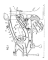
- FIG. 1 illustrates a turbomachine combustion chamber according to the invention.
- the turbomachine has a compression section (no shown) in which air is compressed before being injected into a chamber housing 2, then into a combustion chamber 4 mounted inside of it.
- the compressed air is introduced into the combustion chamber and mixed with fuel before burning.
- the gases resulting from this combustion are then directed to a high-pressure turbine 6 arranged at the outlet of the combustion chamber 4.
- the combustion chamber 4 which is of annular type, is formed of an inner annular wall 4a and an outer annular wall 4b which are joined by a transverse wall 4c forming a bottom of bedroom.
- the inner walls 4a and outer 4b extend along an axis longitudinal X-X slightly inclined relative to the longitudinal axis Y-Y of the turbomachine.
- the chamber bottom 4c is provided with a plurality openings 8 in which are mounted fuel injectors 10.
- the chamber case 2 which is formed of an inner envelope 2a and an outer shell 2b, clean with the chamber of combustion 4 an annular space 12 in which compressed air is admitted intended for combustion, dilution and cooling of the chamber.
- Chamber 4 is divided into a primary zone (or combustion zone) and a secondary zone (or dilution zone) located downstream from the previous one.
- the air that feeds the primary and secondary areas of the combustion chamber 4 is introduced by one or more rows of holes 14, 16 made respectively in the inner walls 4a and external 4b of the room.
- the inner walls 4a and outer 4b of the chamber 4 are extend at their downstream end respectively by flanges (or annular tabs 18 and outer 20.
- the compressed air circulating in the annular space 12 is also intended to feed a cooling circuit of the high-pressure turbine 6 of the turbomachine.
- the internal flange 18 for holding the chamber of combustion 4 is provided with air supply holes 26. These holes 26 allow the circulation of air in the annular space 12 downstream of the internal flange 18.
- the inner casing 2a of the chamber casing 2 is pierced by air supply ports 28, for example distributed over single row, which open into the annular space 12 downstream of the internal flange 18 and open out of the chamber housing 2, to an air injector 30.
- This air injector 30 is intended to cool the turbine high pressure 6 of the turbomachine.
- the air supply holes 26 of the flange internal 18 are distributed circumferentially on at least two rows 26a, 26b arranged in staggered rows.
- FIGS. 3 This distribution is shown in particular in FIGS. 3.
- the two rows 26a, 26b of feed holes in air of the inner flange 18 are arranged in staggered rows.
- staggered rows it is meant that the holes of one of the rows 26a, 26b are not aligned with the holes of the other row along the longitudinal axis X-X of the combustion chamber 4.
- the air supply holes 26 of the combustion chamber have a circular section. It is however possible to consider another form of section, for example oblong.
- the holes 26 of the flange internal 18 are distributed in two rows in staggered rows, their section individual can be reduced compared to a classical provision in single row to keep the same overall airflow supplying the air injector 30.
- the distance separating two holes adjacent areas is increased, further reducing the potential risks of break the internal flange at this point.
- the air supply holes 26 of the internal flange 18 are offset radially from the air supply bores 14 of the inner wall 4a of the combustion chamber 4.
- the air supply holes 26 of the internal flange 18 are offset radially relative to the orifices 28 of the inner casing 2a of the chamber casing 2.
Landscapes
- Engineering & Computer Science (AREA)
- Chemical & Material Sciences (AREA)
- Combustion & Propulsion (AREA)
- Mechanical Engineering (AREA)
- General Engineering & Computer Science (AREA)
- Turbine Rotor Nozzle Sealing (AREA)
Abstract
Description
- la figure 1 est une vue en coupe longitudinale d'une chambre de combustion dans son environnement selon un mode de réalisation de l'invention ;
- la figure 2 est une vue partielle en perspective et en écorché de la figure 1 ; et
- la figure 3 est une vue en développé montrant la répartition des trous de la bride interne de la chambre de combustion selon l'invention.
Claims (4)
- Chambre de combustion annulaire (4) de turbomachine, comportant des parois annulaires interne (4a) et externe (4b) réunies par une paroi transversale (4c), les parois interne et externe se prolongeant à leur extrémité aval par des brides de fixation interne (18) et externe (20) destinées à être fixées respectivement sur des enveloppes interne (2a) et externe (2b) d'un carter (2) de la turbomachine pour le maintien en position de la chambre de combustion, la bride interne (18) étant munie d'une pluralité de trous (26) destinés à alimenter en air de refroidissement une turbine haute-pression (6) de la turbomachine, caractérisée en ce que les trous d'alimentation en air (26) de la bride interne (18) sont répartis circonférentiellement sur au moins deux rangées (26a, 26b) disposées en quinconce.
- Chambre selon la revendication 1, dans laquelle les parois interne (4a) et externe (4b) sont munies d'une pluralité de perçages d'alimentation en air (14, 16) de la chambre, caractérisée en ce que les trous d'alimentation en air (26) de la bride interne (18) sont décalés radialement par rapport aux perçages d'alimentation en air (14) de la paroi interne (4a).
- Chambre selon l'une des revendications 1 et 2, dans laquelle l'enveloppe interne (2a) du carter (2) de la turbomachine est munie d'une pluralité d'orifices (28), caractérisée en ce que les trous d'alimentation en air (26) de la bride interne (18) sont décalés radialement par rapport aux orifices (28) de l'enveloppe interne (2a) du carter (2).
- Bride interne (18) de maintien en position pour chambre de combustion (4) de turbomachine selon l'une quelconque des revendications 1 à 3.
Applications Claiming Priority (2)
| Application Number | Priority Date | Filing Date | Title |
|---|---|---|---|
| FR0403924 | 2004-04-15 | ||
| FR0403924A FR2869094B1 (fr) | 2004-04-15 | 2004-04-15 | Chambre de combustion annulaire de turbomachine a bride interne de fixation amelioree |
Publications (2)
| Publication Number | Publication Date |
|---|---|
| EP1593913A1 true EP1593913A1 (fr) | 2005-11-09 |
| EP1593913B1 EP1593913B1 (fr) | 2016-11-16 |
Family
ID=34942026
Family Applications (1)
| Application Number | Title | Priority Date | Filing Date |
|---|---|---|---|
| EP05290623.7A Expired - Lifetime EP1593913B1 (fr) | 2004-04-15 | 2005-03-22 | Chambre de combustion annulaire de turbomachine à bride interne de fixation améliorée |
Country Status (6)
| Country | Link |
|---|---|
| US (1) | US7412834B2 (fr) |
| EP (1) | EP1593913B1 (fr) |
| JP (1) | JP2005300145A (fr) |
| CA (1) | CA2500762C (fr) |
| FR (1) | FR2869094B1 (fr) |
| RU (1) | RU2365822C2 (fr) |
Cited By (3)
| Publication number | Priority date | Publication date | Assignee | Title |
|---|---|---|---|---|
| FR2890156A1 (fr) * | 2005-08-31 | 2007-03-02 | Snecma | Chambre de combustion d'une turbomachine |
| EP2107307A1 (fr) * | 2008-04-03 | 2009-10-07 | Snecma Propulsion Solide | Chambre de combustion de turbine à gaz à parois interne et externe sectorisées |
| FR2944062A1 (fr) * | 2009-04-06 | 2010-10-08 | Snecma | Injecteur d'ergols |
Families Citing this family (11)
| Publication number | Priority date | Publication date | Assignee | Title |
|---|---|---|---|---|
| US7360364B2 (en) * | 2004-12-17 | 2008-04-22 | General Electric Company | Method and apparatus for assembling gas turbine engine combustors |
| US7578134B2 (en) * | 2006-01-11 | 2009-08-25 | General Electric Company | Methods and apparatus for assembling gas turbine engines |
| US8141370B2 (en) * | 2006-08-08 | 2012-03-27 | General Electric Company | Methods and apparatus for radially compliant component mounting |
| FR2922630B1 (fr) * | 2007-10-22 | 2015-11-13 | Snecma | Paroi de chambre de combustion a dilution et refroidissement optimises,chambre de combustion et turbomachine en etant munies |
| US8863527B2 (en) * | 2009-04-30 | 2014-10-21 | Rolls-Royce Corporation | Combustor liner |
| US10995666B2 (en) | 2015-11-13 | 2021-05-04 | General Electric Company | Particle separators for turbomachines and method of operating the same |
| FR3047544B1 (fr) * | 2016-02-10 | 2018-03-02 | Safran Aircraft Engines | Chambre de combustion de turbomachine |
| WO2019022862A1 (fr) * | 2017-07-24 | 2019-01-31 | Siemens Aktiengesellschaft | Agencement de déviation de particules pour réduire l'ingestion de particules dans un moteur à turbine à combustion |
| FR3120895B1 (fr) | 2021-03-16 | 2024-07-12 | Safran Aircraft Engines | Dispositif de joint d’etancheite a labyrinthe |
| US12146660B2 (en) * | 2021-06-07 | 2024-11-19 | General Electric Company | Combustor for a gas turbine engine |
| CN115539986B (zh) * | 2022-09-22 | 2024-03-19 | 中国航发沈阳发动机研究所 | 一种氢燃料蜂巢仿生燃烧室头部结构 |
Citations (3)
| Publication number | Priority date | Publication date | Assignee | Title |
|---|---|---|---|---|
| FR2356000A1 (fr) * | 1976-06-21 | 1978-01-20 | Gen Electric | Dispositif de support de chambre de combustion pour turbomachine |
| US6434821B1 (en) * | 1999-12-06 | 2002-08-20 | General Electric Company | Method of making a combustion chamber liner |
| FR2841591A1 (fr) * | 2002-06-27 | 2004-01-02 | Snecma Moteurs | Circuits de ventilation de la turbine d'une turbomachine |
Family Cites Families (8)
| Publication number | Priority date | Publication date | Assignee | Title |
|---|---|---|---|---|
| US4466239A (en) * | 1983-02-22 | 1984-08-21 | General Electric Company | Gas turbine engine with improved air cooling circuit |
| SU1753783A1 (ru) * | 1990-02-27 | 1996-06-10 | Моторостроительное конструкторское бюро | Камера сгорания газотурбинного двигателя |
| CA2056592A1 (fr) * | 1990-12-21 | 1992-06-22 | Phillip D. Napoli | Chemise de chambre de combustion a refroidissement par gaine d'air a trous multiples avec demarreur a gaine d'air rainuree |
| FR2671857B1 (fr) * | 1991-01-23 | 1994-12-09 | Snecma | Chambre de combustion, notamment pour turbine a gaz, a paroi deformable. |
| US5758504A (en) * | 1996-08-05 | 1998-06-02 | Solar Turbines Incorporated | Impingement/effusion cooled combustor liner |
| US6286317B1 (en) * | 1998-12-18 | 2001-09-11 | General Electric Company | Cooling nugget for a liner of a gas turbine engine combustor having trapped vortex cavity |
| JP3930252B2 (ja) * | 2000-01-07 | 2007-06-13 | 三菱重工業株式会社 | ガスタービン燃焼器 |
| JP2003328778A (ja) * | 2002-05-15 | 2003-11-19 | Mitsubishi Heavy Ind Ltd | ガスタービンの燃焼振動制御システムおよび燃焼振動制御方法 |
-
2004
- 2004-04-15 FR FR0403924A patent/FR2869094B1/fr not_active Expired - Lifetime
-
2005
- 2005-03-22 EP EP05290623.7A patent/EP1593913B1/fr not_active Expired - Lifetime
- 2005-03-23 CA CA2500762A patent/CA2500762C/fr not_active Expired - Lifetime
- 2005-04-07 US US11/100,543 patent/US7412834B2/en active Active
- 2005-04-11 RU RU2005110358/06A patent/RU2365822C2/ru active
- 2005-04-12 JP JP2005114429A patent/JP2005300145A/ja active Pending
Patent Citations (3)
| Publication number | Priority date | Publication date | Assignee | Title |
|---|---|---|---|---|
| FR2356000A1 (fr) * | 1976-06-21 | 1978-01-20 | Gen Electric | Dispositif de support de chambre de combustion pour turbomachine |
| US6434821B1 (en) * | 1999-12-06 | 2002-08-20 | General Electric Company | Method of making a combustion chamber liner |
| FR2841591A1 (fr) * | 2002-06-27 | 2004-01-02 | Snecma Moteurs | Circuits de ventilation de la turbine d'une turbomachine |
Cited By (6)
| Publication number | Priority date | Publication date | Assignee | Title |
|---|---|---|---|---|
| FR2890156A1 (fr) * | 2005-08-31 | 2007-03-02 | Snecma | Chambre de combustion d'une turbomachine |
| EP1760404A1 (fr) * | 2005-08-31 | 2007-03-07 | Snecma | Chambre de combustion d'une turbomachine |
| US7568350B2 (en) | 2005-08-31 | 2009-08-04 | Snecma | Combustion chamber for a turbomachine |
| EP2107307A1 (fr) * | 2008-04-03 | 2009-10-07 | Snecma Propulsion Solide | Chambre de combustion de turbine à gaz à parois interne et externe sectorisées |
| FR2929689A1 (fr) * | 2008-04-03 | 2009-10-09 | Snecma Propulsion Solide Sa | Chambre de combustion de turbine a gaz a parois interne et externe sectorisees |
| FR2944062A1 (fr) * | 2009-04-06 | 2010-10-08 | Snecma | Injecteur d'ergols |
Also Published As
| Publication number | Publication date |
|---|---|
| US20050229606A1 (en) | 2005-10-20 |
| EP1593913B1 (fr) | 2016-11-16 |
| RU2365822C2 (ru) | 2009-08-27 |
| RU2005110358A (ru) | 2006-10-20 |
| JP2005300145A (ja) | 2005-10-27 |
| FR2869094B1 (fr) | 2006-07-21 |
| CA2500762C (fr) | 2012-09-25 |
| FR2869094A1 (fr) | 2005-10-21 |
| US7412834B2 (en) | 2008-08-19 |
| CA2500762A1 (fr) | 2005-10-15 |
Similar Documents
| Publication | Publication Date | Title |
|---|---|---|
| CA2500762C (fr) | Chambre de combustion annulaire de turbomachine a bride interne de fixation amelioree | |
| CA2577523C (fr) | Chambre de combustion annulaire de turbomachine a fixations alternees | |
| CA2649998C (fr) | Agencement d'une bougie du type a semi-conducteur dans une chambre de combustion de moteur a turbine a gaz | |
| US10513987B2 (en) | System for dissipating fuel egress in fuel supply conduit assemblies | |
| JP4641648B2 (ja) | モジュール式燃焼器ドーム | |
| CA2577507C (fr) | Chambre de combustion d'une turbomachine | |
| RU2406937C2 (ru) | Устройство, используемое для направления конструктивного элемента в отверстие, расположенное в стенке камеры сгорания газотурбинного двигателя, камера сгорания газотурбинного двигателя и газотурбинный двигатель, содержащие вышеуказанное устройство | |
| CN107636301B (zh) | 帽屏蔽的点火系统 | |
| CA2987526C (fr) | Paroi annulaire de chambre de combustion a refroidissement optimise | |
| FR2990073A1 (fr) | Bougie d'allumage pour chambre de combustion d'un moteur a turbine a gaz | |
| US7316117B2 (en) | Can-annular turbine combustors comprising swirler assembly and base plate arrangements, and combinations | |
| FR2931225A1 (fr) | Procede de reglage du refroidissement et de la dilution a une interface de chambre de combustion et une chambre de combustion a gaz | |
| FR2962523A1 (fr) | Chambre de combustion et procedes pour attenuer les crissements de la chambre de combustion | |
| RU2660729C2 (ru) | Камера сгорания для турбинного двигателя с равномерным забором воздуха через систему впрыска топлива | |
| FR2841591A1 (fr) | Circuits de ventilation de la turbine d'une turbomachine | |
| KR102112908B1 (ko) | 가스 터빈 연소기 | |
| CA2619372C (fr) | Chambre de diffusion pour moteur a turnine a gaz, chambre de combustion et moteur a turbine a gaz les comportant | |
| FR2979416A1 (fr) | Paroi de chambre de combustion | |
| FR2942640A1 (fr) | Chambre de post-combustion pour turbomachine | |
| US11112116B2 (en) | Gas turbine combustor and gas turbine | |
| FR2905166A1 (fr) | Chambre de combustion annulaire d'une turbomachine. | |
| FR2889732A1 (fr) | Chambre de combustion a tenue thermique amelioree | |
| US11333359B2 (en) | Gas turbine combustor and gas turbine | |
| FR3064050A1 (fr) | Chambre de combustion d'une turbomachine | |
| EP4179256B1 (fr) | Chambre annulaire de combustion pour une turbomachine d'aéronef |
Legal Events
| Date | Code | Title | Description |
|---|---|---|---|
| PUAI | Public reference made under article 153(3) epc to a published international application that has entered the european phase |
Free format text: ORIGINAL CODE: 0009012 |
|
| 17P | Request for examination filed |
Effective date: 20050325 |
|
| AK | Designated contracting states |
Kind code of ref document: A1 Designated state(s): AT BE BG CH CY CZ DE DK EE ES FI FR GB GR HU IE IS IT LI LT LU MC NL PL PT RO SE SI SK TR |
|
| AX | Request for extension of the european patent |
Extension state: AL BA HR LV MK YU |
|
| RIN1 | Information on inventor provided before grant (corrected) |
Inventor name: HERNANDEZ, DIDIER Inventor name: BES, MARTINE Inventor name: TRAHOT, DENIS Inventor name: LEPRETRE, GILLES |
|
| AKX | Designation fees paid |
Designated state(s): DE FR GB IT |
|
| 17Q | First examination report despatched |
Effective date: 20060627 |
|
| GRAP | Despatch of communication of intention to grant a patent |
Free format text: ORIGINAL CODE: EPIDOSNIGR1 |
|
| INTG | Intention to grant announced |
Effective date: 20160525 |
|
| GRAS | Grant fee paid |
Free format text: ORIGINAL CODE: EPIDOSNIGR3 |
|
| GRAA | (expected) grant |
Free format text: ORIGINAL CODE: 0009210 |
|
| AK | Designated contracting states |
Kind code of ref document: B1 Designated state(s): DE FR GB IT |
|
| REG | Reference to a national code |
Ref country code: GB Ref legal event code: FG4D Free format text: NOT ENGLISH |
|
| REG | Reference to a national code |
Ref country code: DE Ref legal event code: R096 Ref document number: 602005050688 Country of ref document: DE |
|
| REG | Reference to a national code |
Ref country code: FR Ref legal event code: PLFP Year of fee payment: 13 |
|
| REG | Reference to a national code |
Ref country code: DE Ref legal event code: R097 Ref document number: 602005050688 Country of ref document: DE |
|
| PLBE | No opposition filed within time limit |
Free format text: ORIGINAL CODE: 0009261 |
|
| STAA | Information on the status of an ep patent application or granted ep patent |
Free format text: STATUS: NO OPPOSITION FILED WITHIN TIME LIMIT |
|
| 26N | No opposition filed |
Effective date: 20170817 |
|
| REG | Reference to a national code |
Ref country code: FR Ref legal event code: PLFP Year of fee payment: 14 |
|
| PGFP | Annual fee paid to national office [announced via postgrant information from national office to epo] |
Ref country code: DE Payment date: 20240220 Year of fee payment: 20 Ref country code: GB Payment date: 20240220 Year of fee payment: 20 |
|
| PGFP | Annual fee paid to national office [announced via postgrant information from national office to epo] |
Ref country code: IT Payment date: 20240220 Year of fee payment: 20 Ref country code: FR Payment date: 20240220 Year of fee payment: 20 |
|
| REG | Reference to a national code |
Ref country code: DE Ref legal event code: R071 Ref document number: 602005050688 Country of ref document: DE |
|
| REG | Reference to a national code |
Ref country code: GB Ref legal event code: PE20 Expiry date: 20250321 |
|
| PG25 | Lapsed in a contracting state [announced via postgrant information from national office to epo] |
Ref country code: GB Free format text: LAPSE BECAUSE OF EXPIRATION OF PROTECTION Effective date: 20250321 |