EP1593894A1 - Befestigungsklemme für Rohre - Google Patents
Befestigungsklemme für Rohre Download PDFInfo
- Publication number
- EP1593894A1 EP1593894A1 EP05100100A EP05100100A EP1593894A1 EP 1593894 A1 EP1593894 A1 EP 1593894A1 EP 05100100 A EP05100100 A EP 05100100A EP 05100100 A EP05100100 A EP 05100100A EP 1593894 A1 EP1593894 A1 EP 1593894A1
- Authority
- EP
- European Patent Office
- Prior art keywords
- clamp
- arms
- pipe
- base
- arm
- Prior art date
- Legal status (The legal status is an assumption and is not a legal conclusion. Google has not performed a legal analysis and makes no representation as to the accuracy of the status listed.)
- Granted
Links
Images

Classifications
-
- F—MECHANICAL ENGINEERING; LIGHTING; HEATING; WEAPONS; BLASTING
- F16—ENGINEERING ELEMENTS AND UNITS; GENERAL MEASURES FOR PRODUCING AND MAINTAINING EFFECTIVE FUNCTIONING OF MACHINES OR INSTALLATIONS; THERMAL INSULATION IN GENERAL
- F16L—PIPES; JOINTS OR FITTINGS FOR PIPES; SUPPORTS FOR PIPES, CABLES OR PROTECTIVE TUBING; MEANS FOR THERMAL INSULATION IN GENERAL
- F16L3/00—Supports for pipes, cables or protective tubing, e.g. hangers, holders, clamps, cleats, clips, brackets
- F16L3/08—Supports for pipes, cables or protective tubing, e.g. hangers, holders, clamps, cleats, clips, brackets substantially surrounding the pipe, cable or protective tubing
- F16L3/12—Supports for pipes, cables or protective tubing, e.g. hangers, holders, clamps, cleats, clips, brackets substantially surrounding the pipe, cable or protective tubing comprising a member substantially surrounding the pipe, cable or protective tubing
- F16L3/1203—Supports for pipes, cables or protective tubing, e.g. hangers, holders, clamps, cleats, clips, brackets substantially surrounding the pipe, cable or protective tubing comprising a member substantially surrounding the pipe, cable or protective tubing with a pair of arms moved automatically to closed position by overcenter spring
Definitions
- Clamps for pipes or the like which comprise a base for fixing it to a wall or to a support element and a pair of arms which are designed to be adapted to the profile of the pipe are known.
- the arms of said clamps are designed in such a way that they have a semicircular portion, which holds the pipe, and a strut that connects and articulates each arm to the fixing base. Thanks to this configuration, said clamps allow that the arms are automatically closed when they are opened and the pipe is introduced.
- Said clamps allow a fast and easy fastening of the pipes, without need of having to use additional parts.
- the described clamps have the disadvantage that before the pipe is introduced in the clamp, it is necessary to separate the arms to allow introducing the pipe, since if this operation is not carried out, one of the arms is bent inwards and does not allow introducing the pipe.
- this kind of clamps is not adapted to pipes that have small differences of diameters, so it is necessary to have a wide range of clamps for almost each diameter.
- the aim of the present invention is to solve the disadvantages which have the known devices, providing a clamp for pipes and the like, comprising two lateral arms for fixing the pipe between them and articulation means of each arm to a fixing base, each of said arms including a lower end closer to said base which closes the arms when pushing the pipe against it, and an upper end farther from said base which comprises means for blocking both arms when they are closed, characterized in that the upper end of one of said arms is substantially farther from the base than the upper end of the other arm when they are not closed, and in that the articulation means of each arm to the fixing base comprise a constant thickness strut for pressing the arms against the pipe.
- the pipe can be introduced directly in the clamp without need of having to separate the arms previously since, because of one of the arms is longer than the other, it forms an opening through which the pipe is slid.
- the geometry of the clamp becomes asymmetric, this allows its arms to be adapted and to perform an effective fastening for a wider range of diameters of pipes.
- the struts help fastening the pipe more efficiently, as they have a constant thickness all along its length.
- the configuration of the struts allows them acting as a hinging point and a pressure point at the same time, which facilitates that the arms tighten the pipe in a more effective way. This facilitates the arms to be adapted to different diameters of pipes.
- the means for blocking both arms when they are closed comprise a plurality of teeth with a profile complementary to the profile of the teeth of the other arm.
- the teeth allow that the arms are blocked once the pipe has been introduced in the clamp and the arms are closed, and prevent the pipe from being released.
- the teeth have a longitudinal intermediate step for blocking transversal displacement between the arms. Said step improves the fitting of the teeth of both arms, preventing relative displacement between the two arms in the transversal direction and accidental apertures of the clamp.
- the upper end of the arm substantially farther from the base is rounded to facilitate introducing the pipe into the clamp.
- the fixing base comprises means of attachment to a support element fixed to a wall or the like.
- the means of attachment comprise at least a lateral opening in said base which defines a tunnel including a pair of walls provided with longitudinal embossments, part of the support element resting fitted to said longitudinal embossments.
- the longitudinal embossments comprise ribs.
- the support element comprises a plate provided with an orifice coupled to a screw fixed to the wall or the like.
- This metallic plate allows supporting the clamp with a screw in a more solid way without having to machine or form the base of the clamp for that purpose.
- the support element comprises a plug which includes in one of its ends a perimeter groove for fitting it to said ribs by sliding it longitudinally along them.
- the clamp can be fixed quickly and easily without having to hammer or screw it to a wall or the like directly. It is only necessary to fit it to the plug which has already been fixed to the wall.
- the clamp comprises means for blocking the support element when it is attached to the fixing base.
- the means for blocking the support element comprise a flexible flange applied against its end.
- the means of attachment comprise a pair of longitudinal grooves located in both lateral sides of the fixing base for attaching it to a U-shaped profile or the like.
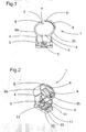
- the clamp 1 of the invention comprises a pair of arms 2a, 2b, one of the arms 2b being longer than the other. Both arms 2a, 2b are attached to a fixing base 3 by means of struts 4, and they include a lower 5 and an upper 6 portion.
- the longer arm 2b defines a vertical opening 7 with regard to the other arm 2a, said opening 7 is wide enough to allow introducing the pipe therein, without having to open the arms 2a, 2b manually.
- the pipe displaces the arms 2a, 2b by sliding them over its surface, and, due to the width of the opening 7, the arms are not bent inwards, but they are displaced laterally and they are opened.
- the upper end 6 of the longer arm 2b is rounded to allow the pipe sliding under it.
- Figure 2 shows teeth 8 present in the upper ends 6 of each arm 2a, 2b, which block the clamp 1 when closed.
- Said teeth 8 have an intermediate step 9 that, once both arms 2a, 2b are attached, prevents transversal displacement between them.
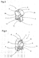
- FIG 4 Operation of the clamp 1 is shown in figure 4.
- the pipe 10 has been introduced by the opening 7, pushing it towards the base 3, in such a way that the arms 2a, 2b are opened sliding over its surface. Once it is situated between both arms 2a, 2b, the pipe 10 is pushed against the lower ends 5, creating a leverage effect that moves the upper ends 6 of both arms 2a, 2b closer to each other until the teeth 8 present in each one of them are automatically coupled.
- the pipe 10 is perfectly fastened, and the struts 4 carry out a supplementary lateral force which presses the arms 2a, 2b against the pipe 10.
- the same clamp 1 can be used for fixing in the same way pipes with considerably different diameters.
- the fact that the longer arm 2b has more teeth 8 than the shorter arm 2a allows blocking the arms 2a, 2b in more positions to adapt them in an optimal way to the diameter of the fixed pipe.
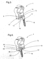
- the base 3 of the clamp 1 is provided with a lateral opening 11 which defines a tunnel 12 that includes, in each of its lateral walls, ribs 13.
- a flexible flange 14 provided with a rim 15 in its front end.
- a plug 18 which will be fixed to the wall, to fix the clamp 1 to the wall (figures 5 and 6).
- the plug 18 is provided with a head 16 which includes a perimeter groove 17 that is introduced inside the tunnel 12, in such a way that the perimeter groove 17 slides longitudinally along the ribs 13, and the flange 14 is displaced upwards.
- the plug 15 reaches the end of the tunnel 12, the flange 14 goes down again and the rim 15 blocks the plug 18 in said position.
- the pipe 1 is fixed in a quick and easy way, sliding it over the head 16 of the plug 18 until it is blocked, without having to use any device.
- a metallic plate 20 provided with a treaded orifice 21 is introduced into a groove 19 at the opposite side of the opening 11 of the base 3, which also communicates with the tunnel 12, until it is aligned with another vertical orifice 22 formed through the base 3.
- said plate acts as a support if the clamp 1 has to be fixed by screwing it, since the screw would be coupled to the orifice 22 of the plate 20 through the vertical orifice 22 of the base 3.
- the base 3 of the clamp comprises a pair of longitudinal grooves 23 to fix them to a U-shaped profile, which makes attaching it easier.
Priority Applications (1)
| Application Number | Priority Date | Filing Date | Title |
|---|---|---|---|
| PL05100100T PL1593894T3 (pl) | 2004-05-05 | 2005-01-10 | Zacisk mocujący do rury |
Applications Claiming Priority (2)
| Application Number | Priority Date | Filing Date | Title |
|---|---|---|---|
| ES200401073U | 2004-05-05 | ||
| ES200401073U ES1057517U (es) | 2004-05-05 | 2004-05-05 | Abrazadera. |
Publications (2)
| Publication Number | Publication Date |
|---|---|
| EP1593894A1 true EP1593894A1 (de) | 2005-11-09 |
| EP1593894B1 EP1593894B1 (de) | 2010-07-07 |
Family
ID=32921846
Family Applications (1)
| Application Number | Title | Priority Date | Filing Date |
|---|---|---|---|
| EP05100100A Not-in-force EP1593894B1 (de) | 2004-05-05 | 2005-01-10 | Befestigungsklemme für Rohre |
Country Status (5)
| Country | Link |
|---|---|
| EP (1) | EP1593894B1 (de) |
| AT (1) | ATE473385T1 (de) |
| DE (1) | DE602005022139D1 (de) |
| ES (2) | ES1057517U (de) |
| PL (1) | PL1593894T3 (de) |
Cited By (1)
| Publication number | Priority date | Publication date | Assignee | Title |
|---|---|---|---|---|
| DE102015110201A1 (de) | 2015-06-25 | 2016-12-29 | Hella Kgaa Hueck & Co. | Befestigungsklammer |
Citations (5)
| Publication number | Priority date | Publication date | Assignee | Title |
|---|---|---|---|---|
| DE7313795U (de) * | 1973-10-18 | Gebauer H | Maschinell montierbare Schelle mit Spreizdübel, zur Befestigung von Kabeln und Rohren | |
| NL8902580A (nl) * | 1989-10-18 | 1991-05-16 | Maskate B V | Buiszadel. |
| US5478033A (en) * | 1994-04-19 | 1995-12-26 | Hungerford, Jr.; Charles S. | Pipe clamp |
| WO1999008032A1 (en) * | 1997-08-05 | 1999-02-18 | J. Van Walraven B.V. | Pipe clip |
| US20030164430A1 (en) * | 2000-07-27 | 2003-09-04 | Clicquick A.G. | Hook closure and pipe clip with such a hook closure |
-
2004
- 2004-05-05 ES ES200401073U patent/ES1057517U/es active Granted
-
2005
- 2005-01-10 EP EP05100100A patent/EP1593894B1/de not_active Not-in-force
- 2005-01-10 AT AT05100100T patent/ATE473385T1/de not_active IP Right Cessation
- 2005-01-10 DE DE602005022139T patent/DE602005022139D1/de active Active
- 2005-01-10 ES ES05100100T patent/ES2346661T3/es active Active
- 2005-01-10 PL PL05100100T patent/PL1593894T3/pl unknown
Patent Citations (5)
| Publication number | Priority date | Publication date | Assignee | Title |
|---|---|---|---|---|
| DE7313795U (de) * | 1973-10-18 | Gebauer H | Maschinell montierbare Schelle mit Spreizdübel, zur Befestigung von Kabeln und Rohren | |
| NL8902580A (nl) * | 1989-10-18 | 1991-05-16 | Maskate B V | Buiszadel. |
| US5478033A (en) * | 1994-04-19 | 1995-12-26 | Hungerford, Jr.; Charles S. | Pipe clamp |
| WO1999008032A1 (en) * | 1997-08-05 | 1999-02-18 | J. Van Walraven B.V. | Pipe clip |
| US20030164430A1 (en) * | 2000-07-27 | 2003-09-04 | Clicquick A.G. | Hook closure and pipe clip with such a hook closure |
Cited By (1)
| Publication number | Priority date | Publication date | Assignee | Title |
|---|---|---|---|---|
| DE102015110201A1 (de) | 2015-06-25 | 2016-12-29 | Hella Kgaa Hueck & Co. | Befestigungsklammer |
Also Published As
| Publication number | Publication date |
|---|---|
| ATE473385T1 (de) | 2010-07-15 |
| ES2346661T3 (es) | 2010-10-19 |
| PL1593894T3 (pl) | 2010-12-31 |
| ES1057517U (es) | 2004-08-16 |
| DE602005022139D1 (de) | 2010-08-19 |
| EP1593894B1 (de) | 2010-07-07 |
Similar Documents
| Publication | Publication Date | Title |
|---|---|---|
| EP1645789B1 (de) | Klemme | |
| US6848683B2 (en) | Arm clamp | |
| US7240930B2 (en) | Quick-connect/quick-disconnect conduit connectors | |
| EP2492563B1 (de) | Klemme für Leitung oder Kabel | |
| US4291855A (en) | Pipe clamp | |
| US9371041B2 (en) | Load carrier foot and a roof rack | |
| US7128560B2 (en) | Expansion tool device for socket pliers | |
| US20090031538A1 (en) | Hose clamp | |
| US6168345B1 (en) | Couplers | |
| CN110462153B (zh) | 用于开关柜壳体的铰链以及相应的开关柜壳体和安装方法 | |
| JPH0266387A (ja) | 管押え | |
| US20050184524A1 (en) | Quick-connect/quick-disconnect conduit connectors | |
| EP1593894A1 (de) | Befestigungsklemme für Rohre | |
| JP2020512516A5 (de) | ||
| KR100971033B1 (ko) | 퀵 조정형 파이프렌치 | |
| EP0437986B1 (de) | Schlauchschelle | |
| BE1018556A5 (fr) | Rallonge de griffes de serrage d'elements electriques. | |
| FR2847327A1 (fr) | Element de maintien pour des faisceaux de conduites tubulaires, faisceaux de cables ou chemins de cables | |
| FR2896760A1 (fr) | Bequille de velo | |
| EP3059826B1 (de) | Aufhängevorrichtung zum aufhängen eines kabels mit einem bestimmten durchmesser an einer halterung | |
| US3966156A (en) | Set of fixing elements for mounting radiators or like bodies on walls | |
| KR20170071264A (ko) | 관체의 이탈방지용 압륜 | |
| KR100900911B1 (ko) | 호스 클램프 체결용 공구 | |
| BE1010158A6 (fr) | Systeme mecanique de securite pour le maintien d'une echelle au niveau d'un toit d'un batiment. | |
| EP0949386A2 (de) | Mehrteiliger Maueranker |
Legal Events
| Date | Code | Title | Description |
|---|---|---|---|
| PUAI | Public reference made under article 153(3) epc to a published international application that has entered the european phase |
Free format text: ORIGINAL CODE: 0009012 |
|
| AK | Designated contracting states |
Kind code of ref document: A1 Designated state(s): AT BE BG CH CY CZ DE DK EE ES FI FR GB GR HU IE IS IT LI LT LU MC NL PL PT RO SE SI SK TR |
|
| AX | Request for extension of the european patent |
Extension state: AL BA HR LV MK YU |
|
| 17P | Request for examination filed |
Effective date: 20051007 |
|
| AKX | Designation fees paid |
Designated state(s): AT BE BG CH CY CZ DE DK EE ES FI FR GB GR HU IE IS IT LI LT LU MC NL PL PT RO SE SI SK TR |
|
| 17Q | First examination report despatched |
Effective date: 20080421 |
|
| GRAP | Despatch of communication of intention to grant a patent |
Free format text: ORIGINAL CODE: EPIDOSNIGR1 |
|
| GRAS | Grant fee paid |
Free format text: ORIGINAL CODE: EPIDOSNIGR3 |
|
| GRAA | (expected) grant |
Free format text: ORIGINAL CODE: 0009210 |
|
| AK | Designated contracting states |
Kind code of ref document: B1 Designated state(s): AT BE BG CH CY CZ DE DK EE ES FI FR GB GR HU IE IS IT LI LT LU MC NL PL PT RO SE SI SK TR |
|
| REG | Reference to a national code |
Ref country code: GB Ref legal event code: FG4D |
|
| REG | Reference to a national code |
Ref country code: CH Ref legal event code: EP |
|
| REG | Reference to a national code |
Ref country code: IE Ref legal event code: FG4D |
|
| REF | Corresponds to: |
Ref document number: 602005022139 Country of ref document: DE Date of ref document: 20100819 Kind code of ref document: P |
|
| REG | Reference to a national code |
Ref country code: NL Ref legal event code: T3 |
|
| REG | Reference to a national code |
Ref country code: ES Ref legal event code: FG2A Ref document number: 2346661 Country of ref document: ES Kind code of ref document: T3 |
|
| PG25 | Lapsed in a contracting state [announced via postgrant information from national office to epo] |
Ref country code: SI Free format text: LAPSE BECAUSE OF FAILURE TO SUBMIT A TRANSLATION OF THE DESCRIPTION OR TO PAY THE FEE WITHIN THE PRESCRIBED TIME-LIMIT Effective date: 20100707 |
|
| LTIE | Lt: invalidation of european patent or patent extension |
Effective date: 20100707 |
|
| REG | Reference to a national code |
Ref country code: PL Ref legal event code: T3 |
|
| PG25 | Lapsed in a contracting state [announced via postgrant information from national office to epo] |
Ref country code: LT Free format text: LAPSE BECAUSE OF FAILURE TO SUBMIT A TRANSLATION OF THE DESCRIPTION OR TO PAY THE FEE WITHIN THE PRESCRIBED TIME-LIMIT Effective date: 20100707 Ref country code: FI Free format text: LAPSE BECAUSE OF FAILURE TO SUBMIT A TRANSLATION OF THE DESCRIPTION OR TO PAY THE FEE WITHIN THE PRESCRIBED TIME-LIMIT Effective date: 20100707 Ref country code: AT Free format text: LAPSE BECAUSE OF FAILURE TO SUBMIT A TRANSLATION OF THE DESCRIPTION OR TO PAY THE FEE WITHIN THE PRESCRIBED TIME-LIMIT Effective date: 20100707 |
|
| PG25 | Lapsed in a contracting state [announced via postgrant information from national office to epo] |
Ref country code: CY Free format text: LAPSE BECAUSE OF FAILURE TO SUBMIT A TRANSLATION OF THE DESCRIPTION OR TO PAY THE FEE WITHIN THE PRESCRIBED TIME-LIMIT Effective date: 20100707 Ref country code: BG Free format text: LAPSE BECAUSE OF FAILURE TO SUBMIT A TRANSLATION OF THE DESCRIPTION OR TO PAY THE FEE WITHIN THE PRESCRIBED TIME-LIMIT Effective date: 20101007 Ref country code: PT Free format text: LAPSE BECAUSE OF FAILURE TO SUBMIT A TRANSLATION OF THE DESCRIPTION OR TO PAY THE FEE WITHIN THE PRESCRIBED TIME-LIMIT Effective date: 20101108 Ref country code: IS Free format text: LAPSE BECAUSE OF FAILURE TO SUBMIT A TRANSLATION OF THE DESCRIPTION OR TO PAY THE FEE WITHIN THE PRESCRIBED TIME-LIMIT Effective date: 20101107 |
|
| PGFP | Annual fee paid to national office [announced via postgrant information from national office to epo] |
Ref country code: PL Payment date: 20101207 Year of fee payment: 7 |
|
| REG | Reference to a national code |
Ref country code: HU Ref legal event code: AG4A Ref document number: E009018 Country of ref document: HU |
|
| PG25 | Lapsed in a contracting state [announced via postgrant information from national office to epo] |
Ref country code: GR Free format text: LAPSE BECAUSE OF FAILURE TO SUBMIT A TRANSLATION OF THE DESCRIPTION OR TO PAY THE FEE WITHIN THE PRESCRIBED TIME-LIMIT Effective date: 20101008 Ref country code: SE Free format text: LAPSE BECAUSE OF FAILURE TO SUBMIT A TRANSLATION OF THE DESCRIPTION OR TO PAY THE FEE WITHIN THE PRESCRIBED TIME-LIMIT Effective date: 20100707 Ref country code: BE Free format text: LAPSE BECAUSE OF FAILURE TO SUBMIT A TRANSLATION OF THE DESCRIPTION OR TO PAY THE FEE WITHIN THE PRESCRIBED TIME-LIMIT Effective date: 20100707 |
|
| PG25 | Lapsed in a contracting state [announced via postgrant information from national office to epo] |
Ref country code: DK Free format text: LAPSE BECAUSE OF FAILURE TO SUBMIT A TRANSLATION OF THE DESCRIPTION OR TO PAY THE FEE WITHIN THE PRESCRIBED TIME-LIMIT Effective date: 20100707 |
|
| PLBE | No opposition filed within time limit |
Free format text: ORIGINAL CODE: 0009261 |
|
| STAA | Information on the status of an ep patent application or granted ep patent |
Free format text: STATUS: NO OPPOSITION FILED WITHIN TIME LIMIT |
|
| PG25 | Lapsed in a contracting state [announced via postgrant information from national office to epo] |
Ref country code: IT Free format text: LAPSE BECAUSE OF FAILURE TO SUBMIT A TRANSLATION OF THE DESCRIPTION OR TO PAY THE FEE WITHIN THE PRESCRIBED TIME-LIMIT Effective date: 20100707 Ref country code: SK Free format text: LAPSE BECAUSE OF FAILURE TO SUBMIT A TRANSLATION OF THE DESCRIPTION OR TO PAY THE FEE WITHIN THE PRESCRIBED TIME-LIMIT Effective date: 20100707 Ref country code: CZ Free format text: LAPSE BECAUSE OF FAILURE TO SUBMIT A TRANSLATION OF THE DESCRIPTION OR TO PAY THE FEE WITHIN THE PRESCRIBED TIME-LIMIT Effective date: 20100707 Ref country code: RO Free format text: LAPSE BECAUSE OF FAILURE TO SUBMIT A TRANSLATION OF THE DESCRIPTION OR TO PAY THE FEE WITHIN THE PRESCRIBED TIME-LIMIT Effective date: 20100707 Ref country code: EE Free format text: LAPSE BECAUSE OF FAILURE TO SUBMIT A TRANSLATION OF THE DESCRIPTION OR TO PAY THE FEE WITHIN THE PRESCRIBED TIME-LIMIT Effective date: 20100707 |
|
| 26N | No opposition filed |
Effective date: 20110408 |
|
| REG | Reference to a national code |
Ref country code: DE Ref legal event code: R097 Ref document number: 602005022139 Country of ref document: DE Effective date: 20110408 |
|
| PG25 | Lapsed in a contracting state [announced via postgrant information from national office to epo] |
Ref country code: MC Free format text: LAPSE BECAUSE OF NON-PAYMENT OF DUE FEES Effective date: 20110131 |
|
| REG | Reference to a national code |
Ref country code: CH Ref legal event code: PL |
|
| REG | Reference to a national code |
Ref country code: IE Ref legal event code: MM4A |
|
| PG25 | Lapsed in a contracting state [announced via postgrant information from national office to epo] |
Ref country code: CH Free format text: LAPSE BECAUSE OF NON-PAYMENT OF DUE FEES Effective date: 20110131 Ref country code: LI Free format text: LAPSE BECAUSE OF NON-PAYMENT OF DUE FEES Effective date: 20110131 |
|
| PG25 | Lapsed in a contracting state [announced via postgrant information from national office to epo] |
Ref country code: IE Free format text: LAPSE BECAUSE OF NON-PAYMENT OF DUE FEES Effective date: 20110110 |
|
| PGFP | Annual fee paid to national office [announced via postgrant information from national office to epo] |
Ref country code: HU Payment date: 20111228 Year of fee payment: 8 |
|
| PGFP | Annual fee paid to national office [announced via postgrant information from national office to epo] |
Ref country code: GB Payment date: 20120104 Year of fee payment: 8 |
|
| PG25 | Lapsed in a contracting state [announced via postgrant information from national office to epo] |
Ref country code: LU Free format text: LAPSE BECAUSE OF NON-PAYMENT OF DUE FEES Effective date: 20110110 |
|
| GBPC | Gb: european patent ceased through non-payment of renewal fee |
Effective date: 20130110 |
|
| PG25 | Lapsed in a contracting state [announced via postgrant information from national office to epo] |
Ref country code: TR Free format text: LAPSE BECAUSE OF FAILURE TO SUBMIT A TRANSLATION OF THE DESCRIPTION OR TO PAY THE FEE WITHIN THE PRESCRIBED TIME-LIMIT Effective date: 20100707 |
|
| PG25 | Lapsed in a contracting state [announced via postgrant information from national office to epo] |
Ref country code: HU Free format text: LAPSE BECAUSE OF NON-PAYMENT OF DUE FEES Effective date: 20130111 |
|
| PG25 | Lapsed in a contracting state [announced via postgrant information from national office to epo] |
Ref country code: GB Free format text: LAPSE BECAUSE OF NON-PAYMENT OF DUE FEES Effective date: 20130110 |
|
| PGFP | Annual fee paid to national office [announced via postgrant information from national office to epo] |
Ref country code: NL Payment date: 20140110 Year of fee payment: 10 |
|
| REG | Reference to a national code |
Ref country code: PL Ref legal event code: LAPE |
|
| PG25 | Lapsed in a contracting state [announced via postgrant information from national office to epo] |
Ref country code: PL Free format text: LAPSE BECAUSE OF NON-PAYMENT OF DUE FEES Effective date: 20130110 |
|
| REG | Reference to a national code |
Ref country code: NL Ref legal event code: V1 Effective date: 20150801 |
|
| PG25 | Lapsed in a contracting state [announced via postgrant information from national office to epo] |
Ref country code: NL Free format text: LAPSE BECAUSE OF NON-PAYMENT OF DUE FEES Effective date: 20150801 |
|
| REG | Reference to a national code |
Ref country code: FR Ref legal event code: PLFP Year of fee payment: 12 |
|
| REG | Reference to a national code |
Ref country code: FR Ref legal event code: PLFP Year of fee payment: 13 |
|
| REG | Reference to a national code |
Ref country code: FR Ref legal event code: PLFP Year of fee payment: 14 |
|
| PGFP | Annual fee paid to national office [announced via postgrant information from national office to epo] |
Ref country code: FR Payment date: 20171211 Year of fee payment: 14 |
|
| PGFP | Annual fee paid to national office [announced via postgrant information from national office to epo] |
Ref country code: DE Payment date: 20171228 Year of fee payment: 14 |
|
| PGFP | Annual fee paid to national office [announced via postgrant information from national office to epo] |
Ref country code: ES Payment date: 20190201 Year of fee payment: 15 |
|
| REG | Reference to a national code |
Ref country code: DE Ref legal event code: R119 Ref document number: 602005022139 Country of ref document: DE |
|
| PG25 | Lapsed in a contracting state [announced via postgrant information from national office to epo] |
Ref country code: DE Free format text: LAPSE BECAUSE OF NON-PAYMENT OF DUE FEES Effective date: 20190801 Ref country code: FR Free format text: LAPSE BECAUSE OF NON-PAYMENT OF DUE FEES Effective date: 20190131 |
|
| REG | Reference to a national code |
Ref country code: ES Ref legal event code: FD2A Effective date: 20210602 |
|
| PG25 | Lapsed in a contracting state [announced via postgrant information from national office to epo] |
Ref country code: ES Free format text: LAPSE BECAUSE OF NON-PAYMENT OF DUE FEES Effective date: 20200111 |