EP1593582A2 - Verfahren zur Steuerung einer elektrischen Servolenkung - Google Patents
Verfahren zur Steuerung einer elektrischen Servolenkung Download PDFInfo
- Publication number
- EP1593582A2 EP1593582A2 EP05101865A EP05101865A EP1593582A2 EP 1593582 A2 EP1593582 A2 EP 1593582A2 EP 05101865 A EP05101865 A EP 05101865A EP 05101865 A EP05101865 A EP 05101865A EP 1593582 A2 EP1593582 A2 EP 1593582A2
- Authority
- EP
- European Patent Office
- Prior art keywords
- steering
- steering handle
- angle
- regulating device
- control
- Prior art date
- Legal status (The legal status is an assumption and is not a legal conclusion. Google has not performed a legal analysis and makes no representation as to the accuracy of the status listed.)
- Granted
Links
Images

Classifications
-
- B—PERFORMING OPERATIONS; TRANSPORTING
- B62—LAND VEHICLES FOR TRAVELLING OTHERWISE THAN ON RAILS
- B62D—MOTOR VEHICLES; TRAILERS
- B62D15/00—Steering not otherwise provided for
- B62D15/02—Steering position indicators ; Steering position determination; Steering aids
- B62D15/021—Determination of steering angle
- B62D15/0235—Determination of steering angle by measuring or deriving directly at the electric power steering motor
-
- B—PERFORMING OPERATIONS; TRANSPORTING
- B62—LAND VEHICLES FOR TRAVELLING OTHERWISE THAN ON RAILS
- B62D—MOTOR VEHICLES; TRAILERS
- B62D15/00—Steering not otherwise provided for
- B62D15/02—Steering position indicators ; Steering position determination; Steering aids
- B62D15/021—Determination of steering angle
- B62D15/0215—Determination of steering angle by measuring on the steering column
-
- B—PERFORMING OPERATIONS; TRANSPORTING
- B62—LAND VEHICLES FOR TRAVELLING OTHERWISE THAN ON RAILS
- B62D—MOTOR VEHICLES; TRAILERS
- B62D5/00—Power-assisted or power-driven steering
- B62D5/04—Power-assisted or power-driven steering electrical, e.g. using an electric servo-motor connected to, or forming part of, the steering gear
- B62D5/0457—Power-assisted or power-driven steering electrical, e.g. using an electric servo-motor connected to, or forming part of, the steering gear characterised by control features of the drive means as such
- B62D5/0481—Power-assisted or power-driven steering electrical, e.g. using an electric servo-motor connected to, or forming part of, the steering gear characterised by control features of the drive means as such monitoring the steering system, e.g. failures
- B62D5/0484—Power-assisted or power-driven steering electrical, e.g. using an electric servo-motor connected to, or forming part of, the steering gear characterised by control features of the drive means as such monitoring the steering system, e.g. failures for reaction to failures, e.g. limp home
-
- B—PERFORMING OPERATIONS; TRANSPORTING
- B62—LAND VEHICLES FOR TRAVELLING OTHERWISE THAN ON RAILS
- B62D—MOTOR VEHICLES; TRAILERS
- B62D6/00—Arrangements for automatically controlling steering depending on driving conditions sensed and responded to, e.g. control circuits
- B62D6/08—Arrangements for automatically controlling steering depending on driving conditions sensed and responded to, e.g. control circuits responsive only to driver input torque
- B62D6/10—Arrangements for automatically controlling steering depending on driving conditions sensed and responded to, e.g. control circuits responsive only to driver input torque characterised by means for sensing or determining torque
Definitions
- the invention relates to a method for controlling an electric power steering and an electric power steering apparatus for performing the method according to The preambles of claims 1 and 14.
- US 6 425 454 B1 describes an electric power steering and a method for the operation of the electric power steering in the case of a steering shaft of a steering torque applied to a driver of a vehicle on a steering handle for steering angle adjustment of one or more steered wheels of the vehicle is transmitted.
- an electric Servomotor provided in which, depending on the at the steering handle entered in a control and / or regulating device steering angle setpoint and a steering torque on the steering handle, a motor torque is generated.
- the engine torque is controlled by an output on the steering shaft and on the steered Transfer wheel or steered wheels.
- the electric power steering has a sensor system consisting of an angle sensor and torque sensor on the Steering handle and u.a.
- a torque sensor for measurement of the torque at the output of the electric servomotor can be omitted since the electric power steering means for estimating the moment at the Steering handle and for estimating the torque at the output of the electric Servomotor has.
- the invention is based on the object, a method for controlling a electric power steering and electric power steering to create the one uncritical behavior in case of malfunction or failure of a torque sensor has on the steering handle.
- the object is achieved by a method for controlling an electric power steering solved with the features of claim 1.
- the method for controlling the Electric power steering will be the virtual moment of the steering handle from the Actual steering angle, the angle of rotation of the output of the electric servomotor, the offset value and the stiffness of the kinematics of the electric power steering of the control and / or regulating device determines and the electric servomotor controlled. Preference is given to the moment of the electric servo motor at a Error of the torque sensor on the steering handle via a stored Transition function, such as a ramp function gradually reduced.
- transition function may also be expedient to consider the transition function to be strictly monotonic Provide function with the same or different pitch.
- the moment of the electric servomotor of the control and / or Control device via a transition function reduces when the virtual Moment the steering handle to a predetermined limit of, for example 2 Nm reduced.
- the sense of direction of the virtual moment of the steering handle changes suddenly and the amount of virtual moment change exceeds one certain limit, which can be specified, so will the electric servomotor preferably switched off by the control and / or regulating device.
- the electric servo motor is also turned off when an offset value due to a Error on an angle sensor on the steering handle or on the output of the electric servomotor can not be determined and the steering angle actual value in the respective driving situation is relatively small and not a predefinable limit exceeds.
- a shutdown of the electric servo motor is for safety reasons acceptable, if the steering angle actual value is smaller than a predefinable limit value, and an error on the angle sensor on the steering handle or an error on the Moment sensor on the steering handle occurs.
- a limit of the actual steering angle value can be about 10 degrees.
- the electric servomotor can also from the control and / or regulating device in combination with the mentioned Criteria or only be turned off when the steering speed a predetermined limit such as 100 ° / sec. exceeds.
- the procedure For controlling the electric power steering is suitable for electric Power steering of passenger cars or commercial vehicles in the same way.
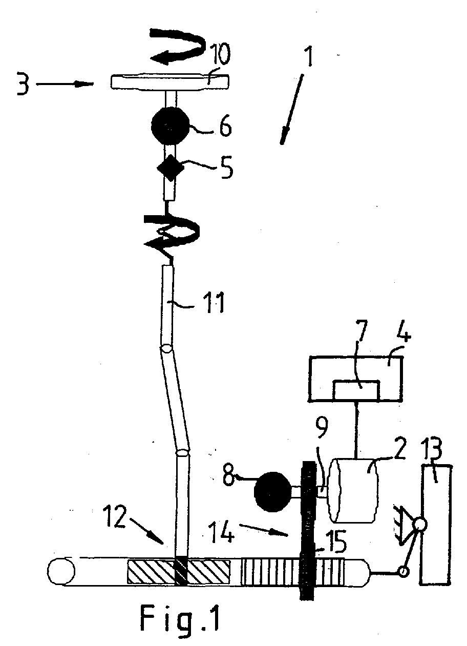
- FIG. 1 shows a schematic view of an electric power steering system 1, the steering handle 10 of which is designed as a steering wheel 10 is mechanically connected via a steering shaft 11 and a rack and pinion steering gear 12 with steerable wheels 13 of a vehicle to their steering angle adjustment.
- An output 9 of an electric servomotor 2 the speed and moment M s is controlled by a control and / or regulating device 4, transmits its torque via a toothed belt 14 to a rack 15 of the rack-and-pinion steering gear 12.
- the rack forms 15th
- the control and / or regulating device 4 processes sensor signals of an angle sensor 6 and a torque sensor 5 on the steering handle 3, and an angle sensor 8 on the output 9 of the electric servo motor. 2
- the angle sensor 6 on the steering handle 3 supplies a steering angle command value ⁇ s and a steering speed value V L.
- the type of drive signal to the electric servomotor 2 may be different, such as a variable voltage signal or a frequency-modulated current signal and may be taken from a map.
- the electric power steering apparatus 1 of the control / or regulating device, and 4 is an offset value ⁇ ⁇ from the steering angle command value ⁇ S and a steering angle value ⁇ L, which also by the angle sensor 8 at the output 9 of the electric servo motor 2 as Angle ⁇ A of the output 9 can be shown formed.
- a virtual torque M v which is approximated to the temperature measured by the torque sensor 5 to the steering handle 3 moment at the steering handle from a device 7 for the estimation of the moment be determined on the steering handle.
- the virtual moment M v is used in a malfunction or failure of the torque sensor 5 on the steering handle 3 to control the electric servomotor 2 of the control and / or regulating device 4.
- FIG. 2 shows a block diagram of a method for controlling the electric servomotor 2 in FIG. 1, which is used on the steering handle 3 when the torque sensor 5 fails.
- the inputted at the steering handle 3 steering angle command value ⁇ s is mechanically transmitted via the steering gear 12, which includes the rack 15 on a steerable wheel 13.
- the electric servomotor 2 acts with its output on the steering gear 12 and provides a moment M s and a rotation angle ⁇ A ready.
- the angle sensor 6 on the steering handle 3 detects the steering angle command value ⁇ s and the steering speed V L on the steering handle 3, the input side of the control and / or regulating device 4 are supplied.
- a torque signal is not provided on the steering handle 3, since the function of the electric power steering 1 is shown in the event of failure of the torque sensor 5 (see FIG.
- An angle sensor 8 detects at the output 9 of the electric servomotor 2 or on the steered wheel 13, the angle ⁇ A of the output 9 and / or the steering angle actual value ⁇ l .
- the device 7 calculates a virtual moment M v for estimating the torque at the steering handle 3 of the control and / or regulating device 4.
- a virtual moment M v for estimating the torque at the steering handle 3 of the control and / or regulating device 4.
- an offset value ⁇ ⁇ from the difference of the steering angle command value ⁇ s and steering angle actual value ⁇ l or instead of the steering angle actual value, by the angle ⁇ A of the output 9 of the electric servomotor 2 is formed.
- the rigidity of the overall system is taken into account.
- the virtual moment M v is used to control the electric servomotor 2.
- the control and / or regulating device 4 checks whether the virtual moment M v by a predeterminable limit lim Mv in the embodiment may be 2 Nm, or has reduced beyond in addition, whether the steering speed V L exceeds a limit lim vL .
- the control and / or regulating device 4 reduces the torque assistance of the electric servomotor 2 via a transition function F when the virtual moment M v exceeds the predefinable limit lim Mv , but the steering speed V L does not exceed the predefinable limit lim vL .
- the transition function F is preferably a ramp function.
- the torque M s of the servomotor 2 is additionally reduced by approximately 30% when the transition function F is applied, which is not irritating to the driver of the vehicle, but rather an indication of a change in the vehicle the power assistance is perceived. If the steering speed V L exceeds the limit value lim vL of, for example, 100 ° / s, then the control and / or regulating device 4 switches off the electric servomotor 2, its moment M s becomes 0 Nm.
Landscapes
- Engineering & Computer Science (AREA)
- Chemical & Material Sciences (AREA)
- Combustion & Propulsion (AREA)
- Transportation (AREA)
- Mechanical Engineering (AREA)
- Steering Control In Accordance With Driving Conditions (AREA)
- Power Steering Mechanism (AREA)
Abstract
Description
- Fig. 1
- zeigt eine schematische Ansicht einer elektrischen Servolenkung,
- Fig. 2
- zeigt in einem Blockschaltbild das Verfahren zur Steuerung der elektrischen Servolenkung bei Ausfall des Momentensensors an der Lenkhandhabe.
Claims (14)
- Verfahren zur Steuerung einer elektrischen Servolenkung (1) für ein Fahrzeug, mit einem elektrischen Servomotor (2), mit einer Lenkhandhabe (3) zur Eingabe eines Lenkwinkel-Sollwertes (δS) in eine Steuer- und/oder Regelungseinrichtung (4), mit einem Momentensensor (5) und einem Winkelsensor (6) für die Lenkhandhabe (3) und mit einer Einrichtung (7) zum Abschätzen des Momentes (Mv) an der Lenkhandhabe (3) und mit einem Winkelsensor (8) zur Bestimmung des Winkels (δA) eines Abtriebs (9) des elektrischen Servomotors (2), dadurch ge- kennzeichnet, dass ständig ein Offsetwert (Δδ) von dem Lenkwinkel-Sollwert (δS) und einem Lenkwinkel-Istwert (δl) ermittelt wird und ein virtuelles Moment (Mv) der Lenkhandhabe (3) anhand des Offsetwertes (Δδ) ermittelt wird.
- Verfahren nach Anspruch 1, dadurch gekennzeichnet, dass das virtuelle Moment (Mv) der Lenkhandhabe (3) aus dem Lenkwinkel-Istwert (δl), dem Winkel (δA) des Abtriebs (9) des elektrischen Servomotors (2), dem Offsetwert (Δδ) und der Steifigkeit der Kinematik der elektrischen Servolenkung (1) von der Steuer- und/oder Regelungseinrichtung (4) ermittelt wird.
- Verfahren nach einem der Ansprüche 1 oder 2, dadurch gekennzeichnet, dass bei einer Fehlfunktion oder einem Ausfall des Momentensensors (5) der Lenkhandhabe (3) in Abhängigkeit von dem virtuellen Moment (Mv) der Lenkhandhabe (3), dem Lenkwinkel-Istwert (δl) und der von der Lenkhandhabe (3) vorgegebenen Lenkgeschwindigkeit (vL) ein Moment (MS) des elektrischen Servomotors (2) von der Steuer- und/oder Regelungseinrichtung (4) über eine Übergangsfunktion (F) reduziert wird.
- Verfahren nach Anspruch 3, dadurch gekennzeichnet, dass die Übergangsfunktion (F) ein Rampenfunktion ist.
- Verfahren nach Anspruch 3, dadurch gekennzeichnet, dass die Übergangsfunktion (F) eine streng monoton fallende Funktion ist.
- Verfahren nach einem der Ansprüche 1 bis 5, dadurch gekennzeichnet, dass das Moment (MS) des elektrischen Servomotors (2) von der Steuer- und/oder Regelungseinrichtung (4) über die Übergangsfunktion (F) reduziert wird, wenn sich das virtuelle Moment (Mv) der Lenkhandhabe (3) bis zu einem vorgebbaren Grenzwert (limMv) verringert hat.
- Verfahren nach Anspruch 6, dadurch gekennzeichnet, dass der Grenzwert (limMv) des virtuellen Moments (Mv) an der Lenkhandhabe (3) etwa 2 Nm ist.
- Verfahren nach einem der Ansprüche 1 bis 5, dadurch gekennzeichnet, dass der elektrische Servomotor (2) von der Steuer- und/oder Regelungseinrichtung (4) abgeschaltet wird, wenn das virtuelle Moment (Mv) der Lenkhandhabe (3) seinen Richtungssinn bei gleichzeitigem Überschreiten des vorgebbaren Grenzwertes (limMv) geändert hat.
- Verfahren nach einem der Ansprüche 1 bis 8, dadurch gekennzeichnet, dass der elektrische Servomotor (2) von der Steuer- und/oder Regelungseinrichtung (4) abgeschaltet wird, wenn ein Fehler an einem Winkelsensor (6,8) der elektrischen Servolenkung (1) von der Steuer- und/oder Regelungseinrichtung (4) erkannt wird.
- Verfahren nach einem der Ansprüche 1 bis 9, dadurch gekennzeichnet, dass der elektrische Servomotor (2) von der Steuer- und/oder Regelungseinrichtung (4) abgeschaltet wird, wenn der Lenkwinkel-Istwert (δl) kleiner als ein vorgebbarer Grenzwert (limδl) ist und ein Fehler an dem Winkelsensor (6) für die Lenkhandhabe (3) oder ein Fehler an dem Momentensensor (5) an der Lenkhandhabe (3) auftritt.
- Verfahren nach Anspruch 10, dadurch gekennzeichnet, dass der Grenzwert (limδl) etwa 10° beträgt.
- Verfahren nach einem der Ansprüche 1 bis 11, dadurch gekennzeichnet, dass der elektrische Servomotor (2) von der Steuer- und/oder Regelungseinrichtung (4) abgeschaltet wird, wenn die Lenkgeschwindigkeit (vL) einen vorgebbaren Grenzwert (limvL) überschreitet.
- Verfahren nach Anspruch 12, dadurch gekennzeichnet, dass der vorgebbare Grenzwert (limvL) etwa 100°/s beträgt.
- Elektrische Servolenkung zur Durchführung des Verfahrens nach einem der Ansprüche 1 bis 13, dadurch gekennzeichnet, dass die elektrische Servolenkung (1) als Hilfskraftlenkung in einem Personenkraftwagen oder Nutzkraftwagen eingebaut ist.
Applications Claiming Priority (2)
| Application Number | Priority Date | Filing Date | Title |
|---|---|---|---|
| DE102004022450A DE102004022450A1 (de) | 2004-05-06 | 2004-05-06 | Verfahren zur Steuerung einer elektrischen Servolenkung |
| DE102004022450 | 2004-05-06 |
Publications (3)
| Publication Number | Publication Date |
|---|---|
| EP1593582A2 true EP1593582A2 (de) | 2005-11-09 |
| EP1593582A3 EP1593582A3 (de) | 2011-10-12 |
| EP1593582B1 EP1593582B1 (de) | 2013-08-21 |
Family
ID=34938941
Family Applications (1)
| Application Number | Title | Priority Date | Filing Date |
|---|---|---|---|
| EP05101865.3A Expired - Lifetime EP1593582B1 (de) | 2004-05-06 | 2005-03-10 | Verfahren zur Steuerung einer elektrischen Servolenkung |
Country Status (3)
| Country | Link |
|---|---|
| US (1) | US7398854B2 (de) |
| EP (1) | EP1593582B1 (de) |
| DE (1) | DE102004022450A1 (de) |
Cited By (4)
| Publication number | Priority date | Publication date | Assignee | Title |
|---|---|---|---|---|
| WO2008058850A1 (de) * | 2006-11-13 | 2008-05-22 | Bayerische Motoren Werke Aktiengesellschaft | Betriebsverfahren für ein lenksystem eines zweispurigen kraftfahrzeugs |
| DE102007003783A1 (de) * | 2007-01-19 | 2008-07-24 | Zf Lenksysteme Gmbh | Verfahren und Steuergerät zum Betrieb einer elektrischen Servolenkung |
| EP1977953A1 (de) * | 2007-04-02 | 2008-10-08 | Jtekt Corporation | Fahrzeuglenkungsgerät |
| FR2920393A1 (fr) * | 2007-08-29 | 2009-03-06 | Peugeot Citroen Automobiles Sa | Procede de mise a jour de la valeur de decalage entre l'angle volant relatif et l'angle volant absolu d'un vehicule automobile |
Families Citing this family (7)
| Publication number | Priority date | Publication date | Assignee | Title |
|---|---|---|---|---|
| DE102006046834A1 (de) * | 2006-10-02 | 2008-04-03 | Robert Bosch Gmbh | Steuergerät in einem Lenksystem eines Fahrzeugs |
| US8126612B2 (en) * | 2008-10-27 | 2012-02-28 | Concordia University | Steering system and method for independent steering of wheels |
| CN103747999B (zh) * | 2011-10-24 | 2016-03-02 | 三菱电机株式会社 | 电动助力转向装置 |
| DE102012102923B4 (de) * | 2012-04-04 | 2015-11-12 | Robert Bosch Automotive Steering Gmbh | Verfahren zum Betreiben einer Hilfskraftlenkung |
| DE102012102924B4 (de) * | 2012-04-04 | 2018-05-09 | Robert Bosch Automotive Steering Gmbh | Verfahren zum Betreiben einer Hilfskraftlenkung |
| DE102013217136B4 (de) * | 2013-08-28 | 2022-11-10 | Volkswagen Aktiengesellschaft | Verfahren zum Reduzieren einer Auswirkung einer Fehlfunktion einer Lenkunterstützung |
| JP6592067B2 (ja) * | 2017-11-29 | 2019-10-16 | 本田技研工業株式会社 | 電動パワーステアリング装置 |
Family Cites Families (13)
| Publication number | Priority date | Publication date | Assignee | Title |
|---|---|---|---|---|
| US4665489A (en) * | 1984-03-15 | 1987-05-12 | Kabushiki Kaisha Meidensha | Unmanned vehicle control system and method |
| DE19748126A1 (de) * | 1997-07-02 | 1999-01-07 | Bosch Gmbh Robert | Verfahren und Vorrichtung zur Überwachung von Sensoren in einem Fahrzeug |
| JP3390333B2 (ja) * | 1997-08-27 | 2003-03-24 | 本田技研工業株式会社 | 電動パワーステアリング装置 |
| DE19755044C1 (de) * | 1997-12-11 | 1999-03-04 | Daimler Benz Ag | Fahrzeuglenkung |
| JP3774599B2 (ja) * | 1999-10-07 | 2006-05-17 | 株式会社ジェイテクト | 電動パワーステアリング装置 |
| US6425454B1 (en) | 2000-02-16 | 2002-07-30 | Ford Global Technologies, Inc. | Vehicle electric power assist steering system and method using velocity based torque estimation |
| JP4128719B2 (ja) * | 2000-02-25 | 2008-07-30 | 三菱電機株式会社 | 電動式パワーステアリング制御装置及びその制御方法 |
| JP3663330B2 (ja) * | 2000-02-29 | 2005-06-22 | 光洋精工株式会社 | 電動パワーステアリング装置 |
| JP3899797B2 (ja) * | 2000-09-25 | 2007-03-28 | 日本精工株式会社 | 電動パワーステアリング装置の制御装置 |
| JP4089197B2 (ja) * | 2001-10-04 | 2008-05-28 | 日本精工株式会社 | 電動パワーステアリング装置の制御装置 |
| US6789017B2 (en) * | 2002-02-15 | 2004-09-07 | Robert Bosch Corporation | Vehicle steering angle position determination method |
| US6816799B2 (en) * | 2002-08-05 | 2004-11-09 | Robert Bosch Corporation | Vehicle operating parameter determination system and method |
| US6895357B2 (en) * | 2002-09-30 | 2005-05-17 | Continental Teves, Inc. | Offset calibration of a semi-relative steering wheel angle sensor |
-
2004
- 2004-05-06 DE DE102004022450A patent/DE102004022450A1/de not_active Withdrawn
-
2005
- 2005-03-10 EP EP05101865.3A patent/EP1593582B1/de not_active Expired - Lifetime
- 2005-04-06 US US11/100,919 patent/US7398854B2/en not_active Expired - Fee Related
Cited By (6)
| Publication number | Priority date | Publication date | Assignee | Title |
|---|---|---|---|---|
| WO2008058850A1 (de) * | 2006-11-13 | 2008-05-22 | Bayerische Motoren Werke Aktiengesellschaft | Betriebsverfahren für ein lenksystem eines zweispurigen kraftfahrzeugs |
| DE102007003783A1 (de) * | 2007-01-19 | 2008-07-24 | Zf Lenksysteme Gmbh | Verfahren und Steuergerät zum Betrieb einer elektrischen Servolenkung |
| EP1977953A1 (de) * | 2007-04-02 | 2008-10-08 | Jtekt Corporation | Fahrzeuglenkungsgerät |
| US8224528B2 (en) | 2007-04-02 | 2012-07-17 | Jtekt Corporation | Vehicle steering apparatus |
| US8744687B2 (en) | 2007-04-02 | 2014-06-03 | Jtekt Corporation | Vehicle steering apparatus |
| FR2920393A1 (fr) * | 2007-08-29 | 2009-03-06 | Peugeot Citroen Automobiles Sa | Procede de mise a jour de la valeur de decalage entre l'angle volant relatif et l'angle volant absolu d'un vehicule automobile |
Also Published As
| Publication number | Publication date |
|---|---|
| US7398854B2 (en) | 2008-07-15 |
| EP1593582B1 (de) | 2013-08-21 |
| US20060000662A1 (en) | 2006-01-05 |
| DE102004022450A1 (de) | 2005-12-01 |
| EP1593582A3 (de) | 2011-10-12 |
Similar Documents
| Publication | Publication Date | Title |
|---|---|---|
| DE602004005804T2 (de) | Lenksteuervorrichtung mit rückstelldrehmomentsteuerung | |
| EP4017785B1 (de) | Kraftfahrzeugservolenkung | |
| DE112016002345B4 (de) | Steuervorrichtung für eine servolenkvorrichtung und servolenkvorrichtung | |
| DE102012204870B4 (de) | Elektrisches Servolenkungssystem für ein Fahrzeug und Fahrzeug | |
| DE60308075T2 (de) | Automatische Lenkeinrichtung für ein Fahrzeug und Steuerverfahren dafür | |
| DE102009020157B4 (de) | Verfahren und Vorrichtung zur Berechnung eines virtuellen Rotorwinkels | |
| DE102016216797A1 (de) | Lenkreaktionskraftsteuervorrichtung für fahrzeug | |
| EP1593582B1 (de) | Verfahren zur Steuerung einer elektrischen Servolenkung | |
| EP1236638B1 (de) | Verfahren und Computerprogramm zum Betrieb einer Fahrzeuglenkung, Steuer- und/oder Regelgerät für eine Fahrzeuglenkung sowie Fahrzeuglenkung | |
| EP3898383B1 (de) | Verfahren zur bestimmung eines lenkgefühls eines steer-by-wire-lenksystems | |
| DE10247975B4 (de) | Verfahren zum Betreiben einer Lenkung, ein Computerprogramm, ein Steuergerät sowie eine Lenkung für ein Fahrzeug | |
| EP4380844B1 (de) | Verfahren zur überwachung eines lenksystems | |
| WO2019048164A1 (de) | Verfahren zum betrieb einer lenkvorrichtung und lenkvorrichtung | |
| WO2023134964A1 (de) | Verfahren zum betrieb eines lenksystems | |
| EP2279396B1 (de) | Verfahren und anordnung zur bestimmung der rotortemperatur eines elektromotors eines hybridfahrzeuges | |
| DE3780516T2 (de) | Motorbetriebene servolenkung fuer fahrzeuge. | |
| DE102019004840A1 (de) | Verfahren zum Betreiben einer motorisch verstellbaren Lenksäule und motorisch verstellbare Lenksäule für ein Kraftfahrzeug | |
| WO2012000574A1 (de) | Verfahren zum elektromechanischen einstellen eines lenkwinkels und kraftfahrzeug mit einer elektromechanischen lenkung | |
| DE102009009448B4 (de) | Verfahren und Vorrichtung zur Eigendiagnose mindestens einer zu diagnostizierenden Sensoreinheit einer elektromechanischen Lenkung | |
| DE10031215C2 (de) | Steuergerät für elektrische Servolenkung | |
| EP1521701B1 (de) | Verfahren zum lenken eines fahrzeugs mit einer überlagerungslenkung | |
| EP2822838B1 (de) | Verfahren zum automatisierten einparken eines mit einem aktiven parklenk-assistenzsystem und einer überlagerungslenkvorrichtung ausgestatteten kraftfahrzeugs | |
| DE102010049431B4 (de) | Verfahren zur Diagnose mindestens einer zu diagnostizierenden Sensoreinheit einer elektromechanischen Lenkung und elektromechanische Lenkung | |
| DE102009011853B4 (de) | Elektrische Servolenkungssysteme für Fahrzeuge mit einstellbaren Drehstabfedern | |
| EP4615740A1 (de) | Mechanisch entkoppeltes lenksystem für ein fahrzeug und verfahren zum betreiben eines mechanisch entkoppelten lenksystems |
Legal Events
| Date | Code | Title | Description |
|---|---|---|---|
| PUAI | Public reference made under article 153(3) epc to a published international application that has entered the european phase |
Free format text: ORIGINAL CODE: 0009012 |
|
| AK | Designated contracting states |
Kind code of ref document: A2 Designated state(s): AT BE BG CH CY CZ DE DK EE ES FI FR GB GR HU IE IS IT LI LT LU MC NL PL PT RO SE SI SK TR |
|
| AX | Request for extension of the european patent |
Extension state: AL BA HR LV MK YU |
|
| PUAL | Search report despatched |
Free format text: ORIGINAL CODE: 0009013 |
|
| AK | Designated contracting states |
Kind code of ref document: A3 Designated state(s): AT BE BG CH CY CZ DE DK EE ES FI FR GB GR HU IE IS IT LI LT LU MC NL PL PT RO SE SI SK TR |
|
| AX | Request for extension of the european patent |
Extension state: AL BA HR LV MK YU |
|
| RIC1 | Information provided on ipc code assigned before grant |
Ipc: B62D 5/04 20060101AFI20110907BHEP |
|
| 17P | Request for examination filed |
Effective date: 20110915 |
|
| AKX | Designation fees paid |
Designated state(s): DE ES FR GB IT SE |
|
| GRAP | Despatch of communication of intention to grant a patent |
Free format text: ORIGINAL CODE: EPIDOSNIGR1 |
|
| INTG | Intention to grant announced |
Effective date: 20130425 |
|
| GRAS | Grant fee paid |
Free format text: ORIGINAL CODE: EPIDOSNIGR3 |
|
| GRAA | (expected) grant |
Free format text: ORIGINAL CODE: 0009210 |
|
| AK | Designated contracting states |
Kind code of ref document: B1 Designated state(s): DE ES FR GB IT SE |
|
| REG | Reference to a national code |
Ref country code: GB Ref legal event code: FG4D Free format text: NOT ENGLISH |
|
| REG | Reference to a national code |
Ref country code: DE Ref legal event code: R096 Ref document number: 502005013925 Country of ref document: DE Effective date: 20131017 |
|
| PG25 | Lapsed in a contracting state [announced via postgrant information from national office to epo] |
Ref country code: SE Free format text: LAPSE BECAUSE OF FAILURE TO SUBMIT A TRANSLATION OF THE DESCRIPTION OR TO PAY THE FEE WITHIN THE PRESCRIBED TIME-LIMIT Effective date: 20130821 |
|
| PG25 | Lapsed in a contracting state [announced via postgrant information from national office to epo] |
Ref country code: ES Free format text: LAPSE BECAUSE OF FAILURE TO SUBMIT A TRANSLATION OF THE DESCRIPTION OR TO PAY THE FEE WITHIN THE PRESCRIBED TIME-LIMIT Effective date: 20130821 Ref country code: IT Free format text: LAPSE BECAUSE OF FAILURE TO SUBMIT A TRANSLATION OF THE DESCRIPTION OR TO PAY THE FEE WITHIN THE PRESCRIBED TIME-LIMIT Effective date: 20130821 |
|
| PLBE | No opposition filed within time limit |
Free format text: ORIGINAL CODE: 0009261 |
|
| STAA | Information on the status of an ep patent application or granted ep patent |
Free format text: STATUS: NO OPPOSITION FILED WITHIN TIME LIMIT |
|
| 26N | No opposition filed |
Effective date: 20140522 |
|
| REG | Reference to a national code |
Ref country code: DE Ref legal event code: R097 Ref document number: 502005013925 Country of ref document: DE Effective date: 20140522 |
|
| REG | Reference to a national code |
Ref country code: DE Ref legal event code: R081 Ref document number: 502005013925 Country of ref document: DE Owner name: ROBERT BOSCH AUTOMOTIVE STEERING GMBH, DE Free format text: FORMER OWNER: ZF LENKSYSTEME GMBH, 73527 SCHWAEBISCH GMUEND, DE Effective date: 20150423 Ref country code: DE Ref legal event code: R081 Ref document number: 502005013925 Country of ref document: DE Owner name: ROBERT BOSCH AUTOMOTIVE STEERING GMBH, DE Free format text: FORMER OWNER: ZF LENKSYSTEME GMBH, 73527 SCHWAEBISCH GMUEND, DE Effective date: 20130828 |
|
| PGFP | Annual fee paid to national office [announced via postgrant information from national office to epo] |
Ref country code: GB Payment date: 20150304 Year of fee payment: 11 |
|
| REG | Reference to a national code |
Ref country code: FR Ref legal event code: PLFP Year of fee payment: 12 |
|
| PGFP | Annual fee paid to national office [announced via postgrant information from national office to epo] |
Ref country code: DE Payment date: 20160302 Year of fee payment: 12 |
|
| PGFP | Annual fee paid to national office [announced via postgrant information from national office to epo] |
Ref country code: FR Payment date: 20160208 Year of fee payment: 12 |
|
| GBPC | Gb: european patent ceased through non-payment of renewal fee |
Effective date: 20160310 |
|
| PG25 | Lapsed in a contracting state [announced via postgrant information from national office to epo] |
Ref country code: GB Free format text: LAPSE BECAUSE OF NON-PAYMENT OF DUE FEES Effective date: 20160310 |
|
| REG | Reference to a national code |
Ref country code: DE Ref legal event code: R119 Ref document number: 502005013925 Country of ref document: DE |
|
| REG | Reference to a national code |
Ref country code: FR Ref legal event code: ST Effective date: 20171130 |
|
| PG25 | Lapsed in a contracting state [announced via postgrant information from national office to epo] |
Ref country code: DE Free format text: LAPSE BECAUSE OF NON-PAYMENT OF DUE FEES Effective date: 20171003 Ref country code: FR Free format text: LAPSE BECAUSE OF NON-PAYMENT OF DUE FEES Effective date: 20170331 |