EP1593561A1 - Seat belt device for vehicle - Google Patents
Seat belt device for vehicle Download PDFInfo
- Publication number
- EP1593561A1 EP1593561A1 EP04703919A EP04703919A EP1593561A1 EP 1593561 A1 EP1593561 A1 EP 1593561A1 EP 04703919 A EP04703919 A EP 04703919A EP 04703919 A EP04703919 A EP 04703919A EP 1593561 A1 EP1593561 A1 EP 1593561A1
- Authority
- EP
- European Patent Office
- Prior art keywords
- collision
- seatbelt
- winding
- vehicle
- load
- Prior art date
- Legal status (The legal status is an assumption and is not a legal conclusion. Google has not performed a legal analysis and makes no representation as to the accuracy of the status listed.)
- Granted
Links
- 238000004804 winding Methods 0.000 claims abstract description 126
- 230000000630 rising effect Effects 0.000 claims abstract description 34
- 238000001514 detection method Methods 0.000 abstract 1
- 238000000034 method Methods 0.000 description 26
- 239000000126 substance Substances 0.000 description 12
- 230000005540 biological transmission Effects 0.000 description 1
- 238000012986 modification Methods 0.000 description 1
- 230000004048 modification Effects 0.000 description 1
Images

Classifications
-
- B—PERFORMING OPERATIONS; TRANSPORTING
- B60—VEHICLES IN GENERAL
- B60R—VEHICLES, VEHICLE FITTINGS, OR VEHICLE PARTS, NOT OTHERWISE PROVIDED FOR
- B60R21/00—Arrangements or fittings on vehicles for protecting or preventing injuries to occupants or pedestrians in case of accidents or other traffic risks
- B60R21/01—Electrical circuits for triggering passive safety arrangements, e.g. airbags, safety belt tighteners, in case of vehicle accidents or impending vehicle accidents
- B60R21/013—Electrical circuits for triggering passive safety arrangements, e.g. airbags, safety belt tighteners, in case of vehicle accidents or impending vehicle accidents including means for detecting collisions, impending collisions or roll-over
-
- B—PERFORMING OPERATIONS; TRANSPORTING
- B60—VEHICLES IN GENERAL
- B60R—VEHICLES, VEHICLE FITTINGS, OR VEHICLE PARTS, NOT OTHERWISE PROVIDED FOR
- B60R22/00—Safety belts or body harnesses in vehicles
- B60R22/34—Belt retractors, e.g. reels
- B60R22/46—Reels with means to tension the belt in an emergency by forced winding up
-
- B—PERFORMING OPERATIONS; TRANSPORTING
- B60—VEHICLES IN GENERAL
- B60R—VEHICLES, VEHICLE FITTINGS, OR VEHICLE PARTS, NOT OTHERWISE PROVIDED FOR
- B60R21/00—Arrangements or fittings on vehicles for protecting or preventing injuries to occupants or pedestrians in case of accidents or other traffic risks
- B60R21/01—Electrical circuits for triggering passive safety arrangements, e.g. airbags, safety belt tighteners, in case of vehicle accidents or impending vehicle accidents
- B60R21/013—Electrical circuits for triggering passive safety arrangements, e.g. airbags, safety belt tighteners, in case of vehicle accidents or impending vehicle accidents including means for detecting collisions, impending collisions or roll-over
- B60R21/0134—Electrical circuits for triggering passive safety arrangements, e.g. airbags, safety belt tighteners, in case of vehicle accidents or impending vehicle accidents including means for detecting collisions, impending collisions or roll-over responsive to imminent contact with an obstacle, e.g. using radar systems
-
- B—PERFORMING OPERATIONS; TRANSPORTING
- B60—VEHICLES IN GENERAL
- B60R—VEHICLES, VEHICLE FITTINGS, OR VEHICLE PARTS, NOT OTHERWISE PROVIDED FOR
- B60R21/00—Arrangements or fittings on vehicles for protecting or preventing injuries to occupants or pedestrians in case of accidents or other traffic risks
- B60R21/01—Electrical circuits for triggering passive safety arrangements, e.g. airbags, safety belt tighteners, in case of vehicle accidents or impending vehicle accidents
- B60R2021/01204—Actuation parameters of safety arrangents
- B60R2021/01252—Devices other than bags
- B60R2021/01265—Seat belts
-
- B—PERFORMING OPERATIONS; TRANSPORTING
- B60—VEHICLES IN GENERAL
- B60R—VEHICLES, VEHICLE FITTINGS, OR VEHICLE PARTS, NOT OTHERWISE PROVIDED FOR
- B60R21/00—Arrangements or fittings on vehicles for protecting or preventing injuries to occupants or pedestrians in case of accidents or other traffic risks
- B60R21/01—Electrical circuits for triggering passive safety arrangements, e.g. airbags, safety belt tighteners, in case of vehicle accidents or impending vehicle accidents
- B60R21/013—Electrical circuits for triggering passive safety arrangements, e.g. airbags, safety belt tighteners, in case of vehicle accidents or impending vehicle accidents including means for detecting collisions, impending collisions or roll-over
- B60R2021/01311—Electrical circuits for triggering passive safety arrangements, e.g. airbags, safety belt tighteners, in case of vehicle accidents or impending vehicle accidents including means for detecting collisions, impending collisions or roll-over monitoring the braking system, e.g. ABS
-
- B—PERFORMING OPERATIONS; TRANSPORTING
- B60—VEHICLES IN GENERAL
- B60R—VEHICLES, VEHICLE FITTINGS, OR VEHICLE PARTS, NOT OTHERWISE PROVIDED FOR
- B60R22/00—Safety belts or body harnesses in vehicles
- B60R22/34—Belt retractors, e.g. reels
- B60R22/46—Reels with means to tension the belt in an emergency by forced winding up
- B60R2022/4685—Reels with means to tension the belt in an emergency by forced winding up with means to adjust or regulate the tensioning force in relation to external parameters
Definitions
- the present invention relates to a vehicle seatbelt apparatus provided with a winder for winding a seatbelt.
- an apparatus of this type is adapted to predict a collision with an object of collision and detect the collision as disclosed in Japanese Unexamined Patent Application Publication No. 6-286581.
- a seatbelt is wound at a first winding load when the collision is predicted.
- the seatbelt is wound at a second winding load which is larger than the first winding load when the collision is detected,
- a vehicle seatbelt apparatus in which a seatbelt is wound at a winding mode and a winding load which can protect a passenger while giving a sense of discomfort as little as possible.
- a characteristic of the vehicle seatbelt apparatus provided with a winder for winding a seatbelt according to the present invention is in that collision predicting means for predicting a collision with an object of collision, and first winding control means for controlling the winder so as to wind the seatbelt at a first winding load when a collision is predicted by the collision predicting means are provided.
- the first winding load may be set, for example to a value between 80N and 120N inclusive.
- the characteristic of the present invention is also in that the collision predicting means for predicting the collision with the object of collision, and the first winding control means for controlling the winder so as to wind the seatbelt while increasing the winding load of the seatbelt at a first rising gradient from a moment when the collision is predicted by the collision predicting means.
- the first rising gradient may be set to a value equal to or larger than 100N/180ms and smaller than 100N/100ms.
- the winding load of the seatbelt which is increased by the first winding control means may be limited up to the first winding load.
- the collision predicting means may be configured to have, for example, a radar device using extremely high-frequency wave (millimetric-wave), or ultrasonic wave, a camera, and the like, and to predict the collision by measuring a length to the object of collision (for example, a vehicle existing in front) and considering a velocity of the vehicle in question with respect to the measured length.
- the collision predicting means may predict the collision with the object of collision by continuously detecting the length from the vehicle in question to the object of collision and, based on the detected length which varies with time. According to the present invention configured in this manner, when the collision is predicted, a constraining force of the seatbelt and variations in the constraining force is restricted, and hence the feeling of discomfort of the passenger due to the constraining force of the seatbelt can be alleviated.
- Another characteristic of the vehicle seatbelt apparatus provided with the collision predicting means and the first winding control means of the present invention is also in that an emergency brake detecting means for detecting an emergency braking state, and second winding control means for controlling the winder so as to wind the seatbelt at a second winding load which is larger than the first winding load when the emergency braking state is detected by the emergency brake detecting means are provided.
- the second winding load may be set, for example, to a value equal to or larger than 150 N.
- Another characteristic of the vehicle seatbelt apparatus provided with the collision predicting means and the first winding control means of the present invention is in that the emergency brake detecting means for detecting the emergency braking state, and the second winding control means for controlling the winder so as to wind the seatbelt while increasing the winding load of the seatbelt at a second rising gradient which is larger than the first rising gradient from a moment when the emergency braking state is detected by the emergency brake detecting means are provided.
- the second rising gradient may be set to a value equal to or larger than, for example, 100N/100ms.
- the winding load of the seatbelt which is increased by the second winding control means may be limited up to the second winding load.
- the emergency brake detecting means may be adapted to detect a pressed amount, a pressing speed, and a pressing force of a brake pedal, or a brake hydraulic pressure and, when the detected value is equal to or larger than the predetermined value, to detect the emergency braking state.
- the emergency braking state in these other characteristics of the present invention is based on the passenger's intension, and hence even when the winding load and the rising gradient of the winding load of the seatbelt is increased to a certain extent, the passenger does not have much feeling of discomfort. Therefore, by carrying out the second winding control in addition to the first winding control described above, the protection of the passenger is ensured without giving much feeling of discomfort to the passenger.
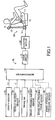
- Fig. 1 schematically shows a vehicle seatbelt apparatus according to the embodiment.
- the vehicle seatbelt apparatus includes a seatbelt mechanism SB and an electric control device EL.
- the seatbelt mechanism SB includes a seatbelt 12 for constraining and protecting a passenger seated on a seat 11.
- the seatbelt 12 is pulled out from a retractor device 13 provided on one side of the seat 11, is slidably supported by a shoulder belt anchor 14 at a midsection thereof, and is fixed to the other side of the seat 11 at the other end thereof.
- the midsection of the seatbelt 12 is provided with a tongue plate 15 assembled so as to be capable of moving.
- the tongue plate 15 is adapted to be detachably fitted to a buckle 16 fixed to the other side of the seat 11.
- the retractor device 13 includes an electric motor 20 for winding the seatbelt 12 in case of emergency, and a mechanism for prohibiting the wound seatbelt 12 from being pulled out.
- the electric control device EL includes a microcomputer 30 having a CPU, a ROM, a RAM, and a timer.
- the microcomputer 30 controls a current amount to be supplied to the electric motor 20 via a drive circuit 31 by repeatedly implementing a winding control program shown in Fig. 2 at predetermined short intervals. Accordingly, a winding load and a rising gradient of the winding load of the seatbelt 12 by the electric motor 20 are controlled.
- a length sensor 41, a vehicle velocity sensor 42, and a brake switch 43 are connected to the microcomputer 30.
- the length sensor 41 includes a radar device using extremely high-frequency wave (millimetric-wave), ultrasonic wave, or the like mounted to a front end of the vehicle, and detects a length Lx from the front end of the vehicle to a substance in front (mainly, a vehicle in front).
- the vehicle velocity sensor 42 detects a vehicle velocity V by counting the number of revolution of an output shaft of a transmission.
- the brake switch 43 having a function to detect sudden braking applied by the passenger, is usually in an OFF-state, and is switched to an ON-state when a brake pedal is deeply pressed.
- the microcomputer 30 By turning on an ignition switch, the microcomputer 30 starts repeated implement of the winding control program shown in Fig. 2 at predetermined short intervals.
- the implement of the winding control program is started in Step 100, the microcomputer 30 inputs a signal indicating the state of the brake switch 43 in Step 102, and determines whether the sudden braking is being operated or not depending on whether or not the same switch 43 is in the ON-state is determined.
- Step 104 the microcomputer 30 inputs the vehicle velocity V detected by the vehicle velocity sensor 42, and determines whether the vehicle velocity V is equal to or higher than a predetermined low vehicle velocity V 0 (for example, 5 km/h) or not, whereby the microcomputer 30 determines whether the vehicle is in a traveling state or not.
- a predetermined low vehicle velocity V 0 for example, 5 km/h
- Step 122 the microcomputer 30 determines whether it is under the winding control of the seatbelt 12 or not in Steps 118, 120 described later. When the microcomputer 30 is not under the winding control of the seatbelt 12, it is determined to be "No" in Step 122, and the implement of the winding control program in Step 128 is ended once.
- Step 106 the length Lx from the front end of the vehicle to the substance in front detected by the length sensor 41 is input, and is set as a new length Lnew indicating the input length by the implement of the program of this time.
- the previous length Lold is set to "0" by an initial setting procedure, not shown.
- the relative velocity Vab calculated at the first time is a negative value, and it is determined to be "No" in Step 112, described later and hence the procedure goes to Step 122. Therefore, even when the relative velocity Vab calculated at the first time is not suitable, this does not cause a problem.
- Step 112 the microcomputer 30 determines whether the same relative velocity Vab is a positive value or not.
- the relative velocity Vab is not a positive value, it is determined to be "No" in Step 112 as described above, and the procedure goes to Step 122. It is because that the fact that the relative velocity Vab is not a positive value means that the length Lx from the front end of the vehicle to the substance in front does not vary, or increases, and in this case, there is no possibility of collision of the vehicle with the substance in front.
- the time Ts is referred to as a collision time.
- the microcomputer 30 determines whether the collision time Ts is equal to or lower than a predetermined time Ts 0 or not.
- the predetermined time Ts 0 is set, for example, to a value on the order of 0. 5 seconds, which is an estimated time that the front end of the vehicle will collide the substance in front unless the passenger (operator) performs a collision avoiding operation such as pressing of the brake pedal or maneuvering of a steering handle or the like quickly.
- Step 116 When the front end collision time Ts is larger than the predetermined time Ts 0 , it is determined to be "No" in Step 116, and the procedure goes to Step 122. On the other hand, when the collision time Ts is equal to or lower than the predetermined time Ts 0 , it is determined to be "Yes” in Step 116, that is, collision predicted, and a first winding control process is carried out in Step 118.
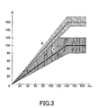
- the current amount flowing in the electric motor 20 is controlled in such a manner that the winding load of the seatbelt 12 is continuously increased at a predetermined first rising gradient (for example, 100N/140ms) and, when it reaches a predetermined first winding load (for example, 100N), the same first winding load is maintained (see a thick solid line in Fig. 3).
- a predetermined first rising gradient for example, 100N/140ms
- a predetermined first winding load for example, 100N
- the same first winding load is maintained (see a thick solid line in Fig. 3).
- the inventors obtained the following experimental result relating the first rising gradient and the first winding load.
- the first rising gradient is equal to, or larger than, 100N/180ms, and smaller than 100N/100ms (range A shown in Fig. 3)
- major part of the people can accept the constraint by the seatbelt 12.
- the first rising gradient is equal to, or larger than 1 00N/100ms
- major part of the people feel that the constraint by the seatbelt 12 is at the acceptable limit, or unacceptable.
- the lower limit value 100N/180ms of the first rising gradient is a value determined from a viewpoint of protection of the passenger.
- the lower limit value 80N of the first winding load is a value determined from a viewpoint of the protection of the passenger.
- Step 120 a case in which a sudden braking operation is performed in order to avoid collision.
- it is determined to be "Yes” that is, the brake switch 43 is in the ON-state, in the above-described Step 102, and a second winding control process is carried out in Step 120.
- the current amount flowing in the electric motor 20 is controlled in such a manner that the winding load of the seatbelt 12 increases continuously at a second rising gradient (for example, 100N/90ms) and, when it reaches the predetermined second winding load (for example, 160N), it is maintained at the second winding load (see a thick broken line in Fig. 3).
- the seatbelt 12 is wound in the retractor device 13, and the passenger is constrained by the seatbelt 12 with a constraining force larger than the case of first winding control.
- the second rising gradient and the second winding load are set to large values from the viewpoint of protection of the passenger.
- the passenger operates the brake, even when the second rising gradient is 100N/100ms or higher, and even when the second winding load is larger than 150N, many people do not have a feeling of discomfort according to the result of the experiment.
- the first winding control is started at a moment when the second winding control is started.
- the current amount flowing in the electric motor 20 is controlled so that the winding load of the seatbelt 12 is increased from the winding load of the seatbelt 12 currently under control to the second winding load at the second rising gradient.
- the seatbelt apparatus when the collision is predicted through the procedure in Steps 104-116, the passenger is constrained at a relatively small winding load of the seatbelt 12 which increases at a relatively small rising gradient by the first winding control process in Step 118. Therefore, the passenger does not have a feeling of discomfort and is protected even when the vehicle collides.
- the sudden braking operation is performed, the sudden braking operation is detected by the process in Step 102, and the passenger is constrained by a winding load which increases at a larger rising gradient than the first winding control and is larger than the same first winding control by the second winding control process in Step 120.
- the passenger since the passenger is conscious of the sudden braking operation, he/she does not have much feeling of discomfort even with a relatively large rising gradient and winding load. Then, even though the vehicle collides, protection of the passenger is ensured.
- Step 124 the microcomputer 30 determines whether conditions of releasing the winding control are satisfied or not. Such release of the winding control of the seatbelt 12 is done because it is desirable to release the passenger from the constraint by the seatbelt 12 after the collision is avoided by the steering operation of the passenger, or the vehicle is stopped even when the collision is occurred.
- Step 124 whether the sudden braking operation by the same procedure as in the above-described Step 102 is released, whether the collision is not predicted through the same procedure as in Steps 104-116, whether the vehicle is in the stopped state, and whether more than the predetermined time is elapsed since the first or the second winding control has started are determined.
- release conditions it is determined to be "No" in Step 124, and implement of the winding control program is ended once in Step 128. In this case, the first or second winding control process continues.
- Step 124 the microcomputer 30 performs a winding control release process for stopping the control of the operation of the electric motor 20 in Step 126, and the implement of the winding control program is ended once in Step 128. Accordingly, the winding load of the seatbelt 12 is reduced, so that the passenger can pull out the seatbelt 12 freely.
- the seatbelt 12 cannot be pulled out even when the winding control of the seatbelt 12 is ended due to a locking function of the retractor device 13, it is necessary to perform a process of releasing the locking function.
- the sudden braking operation is detected by the braking switch 43.
- various methods may be considered as regards the sudden braking operation.
- a brake pedal pressing amount sensor 44 for detecting a pressing amount of the brake pedal, and detect the sudden braking operation under the conditions that the pressing amount of the brake pedal detected by the same sensor 44 or a pressing speed of the brake pedal calculated from the detected pressing amount of the brake pedal is equal to or larger than the predetermined value.
- a brake pedal pressing force sensor 45 for detecting a brake pedal pressing force and detect the sudden braking operation under the conditions that the brake pedal pressing force detected by the same sensor 45 or the varying speed of the brake pedal pressing force calculated from the detected pressing force is equal to or larger than the predetermined value.
- a brake hydraulic pressure sensor 46 for detecting a hydraulic pressure in a route of brake oil (for example, an output side of a master cylinder for the brake), and detect the sudden braking operation under the conditions that the brake hydraulic pressure detected by the same sensor 46 or the varying speed of the brake hydraulic pressure calculated from the detected brake hydraulic pressure is equal to or larger than the predetermined value.
- the length Lx with respect to the substance in front is detected by the radar device using extremely high-frequency wave (millimetric-wave) or ultrasonic wave.
- extremely high-frequency wave millimetric-wave
- ultrasonic wave ultrasonic wave
- prediction of collision is performed by using the vehicle velocity V and the collision time Ts through the process in Steps 104-116.
- the winding of the seatbelt 12 is performed by the rotation of the electric motor 20.
- means other than the electric motor it is also possible to employ means other than the electric motor as long as it enables the winding of the seatbelt 12.
Landscapes
- Engineering & Computer Science (AREA)
- Mechanical Engineering (AREA)
- Radar, Positioning & Navigation (AREA)
- Remote Sensing (AREA)
- Automotive Seat Belt Assembly (AREA)
Abstract
Description
Claims (18)
- A vehicle seatbelt apparatus provided with a winder for winding a seatbelt comprising:collision predicting means for predicting a collision with an object of collision;first winding control means for controlling the winder so as to wind the seatbelt at a first winding load when a collision is predicted by the collision predicting means;emergency brake detecting means for detecting an emergency braking state; andsecond winding control means for controlling the winder so as to wind the seatbelt at a second winding load which is larger than the first winding load when the emergency braking state is detected by the emergency brake detecting means.
- The vehicle seatbelt apparatus according to Claim 1, characterized in that the first winding control means is adapted to increase a winding load of the seatbelt by the winder to the first winding load from a moment when the collision is predicted by the collision predicting means at a first rising gradient, and
the second winding control means is adapted to increase a winding load of the seatbelt by the winder to the second winding load from a moment when the emergency braking state is detected by the emergency brake detecting means at a second rising gradient which is larger than the first rising gradient. - The vehicle seatbelt apparatus according to Claim 2, characterized in that the second rising gradient is set to a value equal to or larger than 100N/100ms.
- The vehicle seatbelt apparatus according to Claim 2 or 3, characterized in that the first rising gradient is set to a value equal to or larger than 100N/180ms and smaller than 100N/100ms.
- The vehicle seatbelt apparatus according to any one of Claims 1 to 4, characterized in that the second winding load is set to a value equal to or larger than 150N.
- The vehicle seatbelt apparatus according to any one of Claims 1 to 5, characterized in that the first winding load is set to a value between 80N and 120 N inclusive.
- The vehicle seatbelt apparatus according to any one of Claims 1 to 6, characterized in that the collision predicting means continuously detects a length from the vehicle in question to the object of collision, and predicts the collision with the object of collision based on the detected length which varies with time.
- The vehicle seatbelt apparatus according any one of Claims 1 to 7, characterized in that the emergency brake detecting means detects the emergency braking state based on at least any one of a pressing amount, a pressing speed, and pressing force of the brake pedal and a brake hydraulic pressure.
- A vehicle seatbelt apparatus provided with a winder for winding a seatbelt comprising:collision predicting means for predicting a collision with an object of collision;first winding control means for controlling the winder so as to wind the seatbelt from a moment when the collision is predicted by the collision predicting means while increasing the winding load of the seatbelt at a first rising gradient;emergency brake detecting means for detecting an emergency braking state; andsecond winding control means for controlling the winder so as to wind the seatbelt while increasing the winding load of the seatbelt at a second rising gradient which is larger than the first rising gradient from a moment when the emergency braking state is detected by the emergency brake detecting means.
- The vehicle seatbelt apparatus according to Claim 9, characterized in that the second rising gradient is set to a value equal to or larger than 100N/100ms.
- The vehicle seatbelt apparatus according to Claim 9 or 10, characterized in that the first rising gradient is set to a value equal to or larger than 100N/180ms and smaller than 100N/100ms.
- The vehicle seatbelt apparatus according to any one of Claims 9 to 11, characterized in that the collision predicting means continuously detects a length from the vehicle in question to the object of collision and detects the collision with the object of collision based on the detected length which varies with time.
- The vehicle seatbelt apparatus according to any one of Claims 9 to 12, characterized in that the emergency brake detecting means detects the emergency braking state based on at least any one of a pressing amount, a pressing speed, and pressing force of the brake pedal and a brake hydraulic pressure.
- A vehicle seatbelt apparatus provided with a winder for winding a seatbelt comprising;
collision predicting means for predicting a collision with an object of collision; and
winding control means for controlling the winder so as to wind the seatbelt at a predetermined winding load between 80N and 120N inclusive when the collision is predicted by the collision predicting means. - The vehicle seatbelt apparatus according to Claim 14, characterized in that the winding control means is adapted to increase the winding load of the seatbelt by the winder to the predetermined winding load from a moment when the collision is predicted by the collision predicting means at a predetermined rising gradient equal to or larger than 100N/180ms and smaller than 100N/100ms.
- The vehicle seatbelt apparatus according to Claim 14 or 15, characterized in that the collision predicting means continuously detects a length from the vehicle in question to the object of collision, and predicts the collision with the object of collision based on the detected length which varies with time.
- A vehicle seatbelt apparatus provided with a winder for winding a seatbelt comprising:collision predicting means for predicting a collision with an object of collision, andwinding control means for controlling the winder so as to wind the seatbelt while increasing the winding load of the seatbelt from a moment when the collision is predicted by the collision predicting means at a predetermined rising gradient equal to or larger than 100N/180ms and smaller than 100N/100ms.
- The vehicle seatbelt apparatus according to Claim 17, characterized in that the collision predicting means continuously detects a length from the vehicle in question to the object of collision and predicts the collision with the object of collision based on the detected length which varies with time.
Applications Claiming Priority (3)
| Application Number | Priority Date | Filing Date | Title |
|---|---|---|---|
| JP2003012646A JP3949061B2 (en) | 2003-01-21 | 2003-01-21 | Vehicle seat belt device |
| JP2003012646 | 2003-01-21 | ||
| PCT/JP2004/000472 WO2004065181A1 (en) | 2003-01-21 | 2004-01-21 | Seat belt device for vehicle |
Publications (3)
| Publication Number | Publication Date |
|---|---|
| EP1593561A1 true EP1593561A1 (en) | 2005-11-09 |
| EP1593561A4 EP1593561A4 (en) | 2006-01-18 |
| EP1593561B1 EP1593561B1 (en) | 2007-05-30 |
Family
ID=32767337
Family Applications (1)
| Application Number | Title | Priority Date | Filing Date |
|---|---|---|---|
| EP04703919A Expired - Lifetime EP1593561B1 (en) | 2003-01-21 | 2004-01-21 | Seat belt device for vehicle |
Country Status (7)
| Country | Link |
|---|---|
| US (1) | US7654573B2 (en) |
| EP (1) | EP1593561B1 (en) |
| JP (1) | JP3949061B2 (en) |
| KR (1) | KR100634777B1 (en) |
| CN (1) | CN100348444C (en) |
| DE (1) | DE602004006721T2 (en) |
| WO (1) | WO2004065181A1 (en) |
Cited By (5)
| Publication number | Priority date | Publication date | Assignee | Title |
|---|---|---|---|---|
| EP1586490A4 (en) * | 2003-01-24 | 2006-03-22 | Honda Motor Co Ltd | Travel safety device for motor vehicle |
| WO2006044953A1 (en) * | 2004-10-19 | 2006-04-27 | Autoliv Asp, Inc. | Adaptive restraint system with retractor having pretensioner |
| WO2006050897A1 (en) * | 2004-11-10 | 2006-05-18 | Daimlerchrysler Ag | Preventive protection system in a motor vehicle |
| WO2006072283A1 (en) * | 2004-12-24 | 2006-07-13 | Daimlerchrysler Ag | Method for a preventatively acting protection system in a motor vehicle |
| EP2650180A1 (en) * | 2012-04-10 | 2013-10-16 | Autoliv Development AB | Method for triggering a motorized retractor for a safety belt system of a vehicle |
Families Citing this family (30)
| Publication number | Priority date | Publication date | Assignee | Title |
|---|---|---|---|---|
| DE10318417B4 (en) * | 2003-04-23 | 2006-04-13 | Faurecia Autositze Gmbh & Co. Kg | Adjustment arrangement for pre-crash adjustment of a vehicle component, in particular a vehicle seat |
| US7318607B2 (en) | 2004-10-19 | 2008-01-15 | Autoliv Asp, Inc. | Adaptive restraint system with retractor pretensioner |
| US7581757B2 (en) | 2004-10-19 | 2009-09-01 | Autoliv Asp, Inc. | Retractor with pretensioner |
| US7963473B2 (en) | 2004-10-19 | 2011-06-21 | Autoliv Asp, Inc. | Retractor with pretensioner |
| DE112004002998A5 (en) * | 2004-11-10 | 2007-09-20 | Daimlerchrysler Ag | Method for a preventive protection system in a motor vehicle |
| US8068956B2 (en) * | 2004-12-23 | 2011-11-29 | Daimler Ag | Restraining device for an occupant of a vehicle |
| JP4501880B2 (en) * | 2006-03-22 | 2010-07-14 | トヨタ自動車株式会社 | Crew protection device |
| US7806357B2 (en) | 2006-07-07 | 2010-10-05 | Autoliv Asp, Inc | Retractor pretensioner with clutch |
| JP4875946B2 (en) * | 2006-08-11 | 2012-02-15 | 本田技研工業株式会社 | Vehicle seat belt device |
| JP4851485B2 (en) * | 2007-04-27 | 2012-01-11 | 本田技研工業株式会社 | VEHICLE CONTROL DEVICE AND SEAT BELT DEVICE CONTROL METHOD |
| KR100931162B1 (en) | 2007-11-21 | 2009-12-10 | 대성전기공업 주식회사 | Vehicle seat belt device and control method thereof |
| JP4911040B2 (en) * | 2008-01-15 | 2012-04-04 | トヨタ自動車株式会社 | Crew protection device |
| JP4729111B2 (en) * | 2009-02-13 | 2011-07-20 | 本田技研工業株式会社 | Vehicle seat belt device |
| CN102791540B (en) * | 2010-03-04 | 2015-12-16 | 本田技研工业株式会社 | The seat belt apparatus of vehicle |
| JP5229507B2 (en) * | 2010-03-30 | 2013-07-03 | 株式会社デンソー | Vehicle distance sensor |
| EP2492159B1 (en) * | 2011-02-28 | 2013-12-25 | Volvo Car Corporation | Method and system for seat belt retraction speed control |
| GB2489464B (en) * | 2011-03-29 | 2013-08-07 | Jaguar Cars | Actuation of an active device of a vehicle under braking |
| GB201105277D0 (en) * | 2011-03-29 | 2011-05-11 | Jaguar Cars | Speed and category trigger for an active device of a vehicle |
| CN102935868B (en) * | 2011-08-15 | 2014-08-06 | 久鼎金属实业股份有限公司 | A variable-speed bicycle capable of identifying abnormal conditions and its identification method |
| CN102874210B (en) * | 2012-06-18 | 2016-01-20 | 浙江吉利汽车研究院有限公司杭州分公司 | Device for preventing safety belt from being tied in false state |
| CN102774349B (en) * | 2012-07-27 | 2015-06-03 | 浙江吉利汽车研究院有限公司杭州分公司 | Auxiliary device and auxiliary method for pre-tightening motor type safety belt |
| CN103121434A (en) * | 2013-02-28 | 2013-05-29 | 安徽江淮汽车股份有限公司 | Safety belt tightening system and method |
| US9266487B2 (en) * | 2014-03-17 | 2016-02-23 | Ford Global Technologies, Llc | Adaptive suppression of vehicle restraint system |
| EP3018010B1 (en) * | 2014-11-06 | 2018-01-10 | Volvo Car Corporation | Method for controlling a time of activation of a reversible restraint system in a vehicle |
| JP6364436B2 (en) * | 2016-03-22 | 2018-07-25 | 株式会社Subaru | Vehicle occupant protection device |
| JP6493354B2 (en) | 2016-10-13 | 2019-04-03 | トヨタ自動車株式会社 | Vehicle occupant restraint system |
| JP6767276B2 (en) | 2017-02-07 | 2020-10-14 | トヨタ自動車株式会社 | Vehicle occupant restraint device |
| JP2018203211A (en) * | 2017-06-09 | 2018-12-27 | 株式会社東海理化電機製作所 | Seat belt retractor |
| DE102017210301A1 (en) | 2017-06-20 | 2018-12-20 | Robert Bosch Gmbh | Method and control device for controlling an emergency braking function of a vehicle |
| DE102018210794A1 (en) * | 2018-06-29 | 2020-01-02 | Robert Bosch Gmbh | Method for triggering an occupant protection device in a vehicle |
Family Cites Families (19)
| Publication number | Priority date | Publication date | Assignee | Title |
|---|---|---|---|---|
| JP2946995B2 (en) * | 1993-03-31 | 1999-09-13 | 日産自動車株式会社 | Vehicle seat belt device |
| JP3467339B2 (en) * | 1994-12-20 | 2003-11-17 | タカタ株式会社 | Vehicle collision state control system |
| JP4142750B2 (en) * | 1995-09-08 | 2008-09-03 | タカタ株式会社 | Vehicle occupant restraint protection system |
| GB2333077B (en) | 1995-09-08 | 1999-12-15 | Takata Corp | Vehicle occupant restraint system |
| SE9801261D0 (en) * | 1998-04-07 | 1998-04-07 | Stridsberg Innovation Ab | Safety belt tensioners |
| JP3837909B2 (en) * | 1998-05-22 | 2006-10-25 | マツダ株式会社 | Vehicle occupant protection device |
| JP2000118352A (en) * | 1998-10-14 | 2000-04-25 | Takata Corp | Seat belt retractor and seat belt device |
| JP2001151076A (en) * | 1999-11-29 | 2001-06-05 | Takata Corp | Occupant restraint protection system |
| DE19961799B4 (en) * | 1999-12-21 | 2004-03-25 | Breed Automotive Technology, Inc., Lakeland | Passive safety system of a motor vehicle |
| DE10005010C2 (en) | 2000-02-04 | 2002-11-21 | Daimler Chrysler Ag | Method and safety restraint for restraining an occupant in a vehicle seat |
| US6726249B2 (en) * | 2000-05-26 | 2004-04-27 | Takata Corporation | Motorized seat belt retractor |
| DE10029061C2 (en) * | 2000-06-13 | 2003-12-11 | Breed Automotive Tech | Restraint |
| EP1219510B1 (en) * | 2000-12-28 | 2006-04-12 | TAKATA-PETRI (Ulm) GmbH | Belt force limiting device in a seatbelt retractor |
| JP3858592B2 (en) * | 2000-12-28 | 2006-12-13 | 日産自動車株式会社 | Crew protection device |
| JP3601511B2 (en) | 2001-12-18 | 2004-12-15 | トヨタ自動車株式会社 | Seat belt equipment |
| US6722698B2 (en) * | 2002-03-22 | 2004-04-20 | General Motors Corporation | Seat belt retractor system |
| JP3562519B2 (en) * | 2002-09-30 | 2004-09-08 | 日産自動車株式会社 | Vehicle seat belt device |
| JP4082177B2 (en) * | 2002-10-30 | 2008-04-30 | トヨタ自動車株式会社 | Vehicle safety device |
| US7140571B2 (en) * | 2003-06-11 | 2006-11-28 | Autoliv, Asp, Inc. | Electric seat belt retractor system |
-
2003
- 2003-01-21 JP JP2003012646A patent/JP3949061B2/en not_active Expired - Fee Related
-
2004
- 2004-01-21 EP EP04703919A patent/EP1593561B1/en not_active Expired - Lifetime
- 2004-01-21 KR KR1020057013469A patent/KR100634777B1/en not_active Expired - Fee Related
- 2004-01-21 DE DE602004006721T patent/DE602004006721T2/en not_active Expired - Lifetime
- 2004-01-21 US US10/542,949 patent/US7654573B2/en not_active Expired - Lifetime
- 2004-01-21 WO PCT/JP2004/000472 patent/WO2004065181A1/en not_active Ceased
- 2004-01-21 CN CNB2004800025287A patent/CN100348444C/en not_active Expired - Fee Related
Cited By (6)
| Publication number | Priority date | Publication date | Assignee | Title |
|---|---|---|---|---|
| EP1586490A4 (en) * | 2003-01-24 | 2006-03-22 | Honda Motor Co Ltd | Travel safety device for motor vehicle |
| WO2006044953A1 (en) * | 2004-10-19 | 2006-04-27 | Autoliv Asp, Inc. | Adaptive restraint system with retractor having pretensioner |
| WO2006050897A1 (en) * | 2004-11-10 | 2006-05-18 | Daimlerchrysler Ag | Preventive protection system in a motor vehicle |
| WO2006072283A1 (en) * | 2004-12-24 | 2006-07-13 | Daimlerchrysler Ag | Method for a preventatively acting protection system in a motor vehicle |
| US7954590B2 (en) | 2004-12-24 | 2011-06-07 | Daimler Ag | Method for a preventive-action protection system in a motor vehicle |
| EP2650180A1 (en) * | 2012-04-10 | 2013-10-16 | Autoliv Development AB | Method for triggering a motorized retractor for a safety belt system of a vehicle |
Also Published As
| Publication number | Publication date |
|---|---|
| US7654573B2 (en) | 2010-02-02 |
| JP2004262256A (en) | 2004-09-24 |
| EP1593561B1 (en) | 2007-05-30 |
| WO2004065181A1 (en) | 2004-08-05 |
| DE602004006721D1 (en) | 2007-07-12 |
| CN1741926A (en) | 2006-03-01 |
| US20060237960A1 (en) | 2006-10-26 |
| DE602004006721T2 (en) | 2008-01-24 |
| EP1593561A4 (en) | 2006-01-18 |
| KR100634777B1 (en) | 2006-10-16 |
| CN100348444C (en) | 2007-11-14 |
| JP3949061B2 (en) | 2007-07-25 |
| KR20050105441A (en) | 2005-11-04 |
Similar Documents
| Publication | Publication Date | Title |
|---|---|---|
| EP1593561B1 (en) | Seat belt device for vehicle | |
| US7686118B2 (en) | Seatbelt apparatus | |
| JP4591750B2 (en) | Vehicle occupant protection device | |
| US6846019B2 (en) | Seatbelt apparatus for vehicle | |
| JP2003182519A (en) | Seat belt equipment | |
| US6959613B2 (en) | Seatbelt apparatus for vehicle | |
| KR101514419B1 (en) | Vehicle Passenger Security Control System and Control Method thereof | |
| CN100548752C (en) | seat belt pretensioner | |
| JP3951959B2 (en) | Vehicle seat belt device | |
| JP4333305B2 (en) | Electric parking brake system | |
| JP4114492B2 (en) | Vehicle seat belt device | |
| JP3951958B2 (en) | Vehicle seat belt device | |
| JP4007245B2 (en) | Vehicle seat belt device | |
| JP2000326824A5 (en) | ||
| JP2004284381A (en) | Occupant protection device | |
| JP2004149042A (en) | Vehicle seat belt device | |
| JP2004149049A (en) | Vehicle seat belt device | |
| KR100557322B1 (en) | Vehicle collision detection device and method | |
| JP2008024134A (en) | Seat belt device | |
| CN111038439A (en) | Control device for seat belt of vehicle | |
| JP2008024133A (en) | Seat belt device | |
| JP2004322689A (en) | Vehicle seat belt device |
Legal Events
| Date | Code | Title | Description |
|---|---|---|---|
| PUAI | Public reference made under article 153(3) epc to a published international application that has entered the european phase |
Free format text: ORIGINAL CODE: 0009012 |
|
| 17P | Request for examination filed |
Effective date: 20050809 |
|
| AK | Designated contracting states |
Kind code of ref document: A1 Designated state(s): AT BE BG CH CY CZ DE DK EE ES FI FR GB GR HU IE IT LI LU MC NL PT RO SE SI SK TR |
|
| AX | Request for extension of the european patent |
Extension state: AL LT LV MK |
|
| A4 | Supplementary search report drawn up and despatched |
Effective date: 20051202 |
|
| RAP1 | Party data changed (applicant data changed or rights of an application transferred) |
Owner name: DENSO CORPORATION Owner name: TOYOTA JIDOSHA KABUSHIKI KAISHA |
|
| RAP1 | Party data changed (applicant data changed or rights of an application transferred) |
Owner name: DENSO CORPORATION Owner name: TOYOTA JIDOSHA KABUSHIKI KAISHA |
|
| DAX | Request for extension of the european patent (deleted) | ||
| RBV | Designated contracting states (corrected) |
Designated state(s): DE FR GB |
|
| GRAP | Despatch of communication of intention to grant a patent |
Free format text: ORIGINAL CODE: EPIDOSNIGR1 |
|
| GRAJ | Information related to disapproval of communication of intention to grant by the applicant or resumption of examination proceedings by the epo deleted |
Free format text: ORIGINAL CODE: EPIDOSDIGR1 |
|
| GRAP | Despatch of communication of intention to grant a patent |
Free format text: ORIGINAL CODE: EPIDOSNIGR1 |
|
| GRAS | Grant fee paid |
Free format text: ORIGINAL CODE: EPIDOSNIGR3 |
|
| RIN1 | Information on inventor provided before grant (corrected) |
Inventor name: KUDO, TOSHIYA,C/O TOYOTA JIDOSHA KABUSHIKI KAISHA Inventor name: KACHUU, RYOUTAROU,C/O TOYOTA JIDOSHA KABUSHIKI KAI Inventor name: KATO, HIDEKI,C/O TOYOTA JIDOSHA KABUSHIKI KAISHA Inventor name: NEZAKI, TAKUYA,C/O TOYOTA JIDOSHA KABUSHIKI KAISHA Inventor name: ISAJI, KAZUYOSHI,C/O DENSO CORPORATION |
|
| GRAA | (expected) grant |
Free format text: ORIGINAL CODE: 0009210 |
|
| RAP1 | Party data changed (applicant data changed or rights of an application transferred) |
Owner name: DENSO CORPORATION Owner name: TOYOTA JIDOSHA KABUSHIKI KAISHA |
|
| AK | Designated contracting states |
Kind code of ref document: B1 Designated state(s): DE FR GB |
|
| REG | Reference to a national code |
Ref country code: GB Ref legal event code: FG4D |
|
| REF | Corresponds to: |
Ref document number: 602004006721 Country of ref document: DE Date of ref document: 20070712 Kind code of ref document: P |
|
| ET | Fr: translation filed | ||
| PLBE | No opposition filed within time limit |
Free format text: ORIGINAL CODE: 0009261 |
|
| STAA | Information on the status of an ep patent application or granted ep patent |
Free format text: STATUS: NO OPPOSITION FILED WITHIN TIME LIMIT |
|
| 26N | No opposition filed |
Effective date: 20080303 |
|
| REG | Reference to a national code |
Ref country code: FR Ref legal event code: PLFP Year of fee payment: 13 |
|
| REG | Reference to a national code |
Ref country code: DE Ref legal event code: R084 Ref document number: 602004006721 Country of ref document: DE |
|
| REG | Reference to a national code |
Ref country code: GB Ref legal event code: 746 Effective date: 20161025 |
|
| REG | Reference to a national code |
Ref country code: FR Ref legal event code: PLFP Year of fee payment: 14 |
|
| REG | Reference to a national code |
Ref country code: FR Ref legal event code: PLFP Year of fee payment: 15 |
|
| PGFP | Annual fee paid to national office [announced via postgrant information from national office to epo] |
Ref country code: GB Payment date: 20211206 Year of fee payment: 19 Ref country code: FR Payment date: 20211217 Year of fee payment: 19 |
|
| PGFP | Annual fee paid to national office [announced via postgrant information from national office to epo] |
Ref country code: DE Payment date: 20211130 Year of fee payment: 19 |
|
| REG | Reference to a national code |
Ref country code: DE Ref legal event code: R119 Ref document number: 602004006721 Country of ref document: DE |
|
| GBPC | Gb: european patent ceased through non-payment of renewal fee |
Effective date: 20230121 |
|
| PG25 | Lapsed in a contracting state [announced via postgrant information from national office to epo] |
Ref country code: GB Free format text: LAPSE BECAUSE OF NON-PAYMENT OF DUE FEES Effective date: 20230121 Ref country code: DE Free format text: LAPSE BECAUSE OF NON-PAYMENT OF DUE FEES Effective date: 20230801 |
|
| PG25 | Lapsed in a contracting state [announced via postgrant information from national office to epo] |
Ref country code: FR Free format text: LAPSE BECAUSE OF NON-PAYMENT OF DUE FEES Effective date: 20230131 |