EP1593517A1 - Inkjet recording head and head unit - Google Patents
Inkjet recording head and head unit Download PDFInfo
- Publication number
- EP1593517A1 EP1593517A1 EP05009911A EP05009911A EP1593517A1 EP 1593517 A1 EP1593517 A1 EP 1593517A1 EP 05009911 A EP05009911 A EP 05009911A EP 05009911 A EP05009911 A EP 05009911A EP 1593517 A1 EP1593517 A1 EP 1593517A1
- Authority
- EP
- European Patent Office
- Prior art keywords
- plate
- information recording
- recording head
- head
- disposed
- Prior art date
- Legal status (The legal status is an assumption and is not a legal conclusion. Google has not performed a legal analysis and makes no representation as to the accuracy of the status listed.)
- Granted
Links
- 238000004891 communication Methods 0.000 claims description 4
- 239000002184 metal Substances 0.000 claims description 4
- 229910052751 metal Inorganic materials 0.000 claims description 4
- 229920003002 synthetic resin Polymers 0.000 claims description 3
- 239000000057 synthetic resin Substances 0.000 claims description 3
- 239000010703 silicon Substances 0.000 claims description 2
- 229910052710 silicon Inorganic materials 0.000 claims description 2
- 239000000976 ink Substances 0.000 description 97
- 125000006850 spacer group Chemical group 0.000 description 18
- 238000004519 manufacturing process Methods 0.000 description 13
- 238000005259 measurement Methods 0.000 description 8
- 238000003754 machining Methods 0.000 description 6
- 230000003213 activating effect Effects 0.000 description 5
- 238000010926 purge Methods 0.000 description 5
- 239000000463 material Substances 0.000 description 4
- 238000007639 printing Methods 0.000 description 4
- 239000000853 adhesive Substances 0.000 description 3
- 230000015572 biosynthetic process Effects 0.000 description 3
- 230000002950 deficient Effects 0.000 description 3
- 238000010586 diagram Methods 0.000 description 3
- 238000000034 method Methods 0.000 description 3
- 239000002245 particle Substances 0.000 description 3
- 238000003860 storage Methods 0.000 description 3
- 238000012360 testing method Methods 0.000 description 3
- 239000012780 transparent material Substances 0.000 description 3
- PXHVJJICTQNCMI-UHFFFAOYSA-N Nickel Chemical compound [Ni] PXHVJJICTQNCMI-UHFFFAOYSA-N 0.000 description 2
- 238000005530 etching Methods 0.000 description 2
- 238000010030 laminating Methods 0.000 description 2
- 238000011084 recovery Methods 0.000 description 2
- 229910000990 Ni alloy Inorganic materials 0.000 description 1
- 239000004642 Polyimide Substances 0.000 description 1
- 229910000831 Steel Inorganic materials 0.000 description 1
- 230000004913 activation Effects 0.000 description 1
- 238000004140 cleaning Methods 0.000 description 1
- 238000011109 contamination Methods 0.000 description 1
- 230000000694 effects Effects 0.000 description 1
- 230000005489 elastic deformation Effects 0.000 description 1
- 238000010438 heat treatment Methods 0.000 description 1
- 239000003550 marker Substances 0.000 description 1
- 229910052759 nickel Inorganic materials 0.000 description 1
- 229920001721 polyimide Polymers 0.000 description 1
- 229920001296 polysiloxane Polymers 0.000 description 1
- 230000000717 retained effect Effects 0.000 description 1
- 238000007789 sealing Methods 0.000 description 1
- 238000002791 soaking Methods 0.000 description 1
- 239000010959 steel Substances 0.000 description 1
Images






Classifications
-
- B—PERFORMING OPERATIONS; TRANSPORTING
- B41—PRINTING; LINING MACHINES; TYPEWRITERS; STAMPS
- B41J—TYPEWRITERS; SELECTIVE PRINTING MECHANISMS, i.e. MECHANISMS PRINTING OTHERWISE THAN FROM A FORME; CORRECTION OF TYPOGRAPHICAL ERRORS
- B41J2/00—Typewriters or selective printing mechanisms characterised by the printing or marking process for which they are designed
- B41J2/005—Typewriters or selective printing mechanisms characterised by the printing or marking process for which they are designed characterised by bringing liquid or particles selectively into contact with a printing material
- B41J2/01—Ink jet
- B41J2/17—Ink jet characterised by ink handling
- B41J2/175—Ink supply systems ; Circuit parts therefor
- B41J2/17503—Ink cartridges
- B41J2/17543—Cartridge presence detection or type identification
-
- B—PERFORMING OPERATIONS; TRANSPORTING
- B41—PRINTING; LINING MACHINES; TYPEWRITERS; STAMPS
- B41J—TYPEWRITERS; SELECTIVE PRINTING MECHANISMS, i.e. MECHANISMS PRINTING OTHERWISE THAN FROM A FORME; CORRECTION OF TYPOGRAPHICAL ERRORS
- B41J2/00—Typewriters or selective printing mechanisms characterised by the printing or marking process for which they are designed
- B41J2/005—Typewriters or selective printing mechanisms characterised by the printing or marking process for which they are designed characterised by bringing liquid or particles selectively into contact with a printing material
- B41J2/01—Ink jet
- B41J2/135—Nozzles
- B41J2/14—Structure thereof only for on-demand ink jet heads
- B41J2/14201—Structure of print heads with piezoelectric elements
- B41J2/14209—Structure of print heads with piezoelectric elements of finger type, chamber walls consisting integrally of piezoelectric material
-
- B—PERFORMING OPERATIONS; TRANSPORTING
- B41—PRINTING; LINING MACHINES; TYPEWRITERS; STAMPS
- B41J—TYPEWRITERS; SELECTIVE PRINTING MECHANISMS, i.e. MECHANISMS PRINTING OTHERWISE THAN FROM A FORME; CORRECTION OF TYPOGRAPHICAL ERRORS
- B41J2/00—Typewriters or selective printing mechanisms characterised by the printing or marking process for which they are designed
- B41J2/005—Typewriters or selective printing mechanisms characterised by the printing or marking process for which they are designed characterised by bringing liquid or particles selectively into contact with a printing material
- B41J2/01—Ink jet
- B41J2/135—Nozzles
- B41J2/14—Structure thereof only for on-demand ink jet heads
- B41J2/14201—Structure of print heads with piezoelectric elements
- B41J2/14209—Structure of print heads with piezoelectric elements of finger type, chamber walls consisting integrally of piezoelectric material
- B41J2002/14217—Multi layer finger type piezoelectric element
-
- B—PERFORMING OPERATIONS; TRANSPORTING
- B41—PRINTING; LINING MACHINES; TYPEWRITERS; STAMPS
- B41J—TYPEWRITERS; SELECTIVE PRINTING MECHANISMS, i.e. MECHANISMS PRINTING OTHERWISE THAN FROM A FORME; CORRECTION OF TYPOGRAPHICAL ERRORS
- B41J2/00—Typewriters or selective printing mechanisms characterised by the printing or marking process for which they are designed
- B41J2/005—Typewriters or selective printing mechanisms characterised by the printing or marking process for which they are designed characterised by bringing liquid or particles selectively into contact with a printing material
- B41J2/01—Ink jet
- B41J2/135—Nozzles
- B41J2/14—Structure thereof only for on-demand ink jet heads
- B41J2/14201—Structure of print heads with piezoelectric elements
- B41J2/14209—Structure of print heads with piezoelectric elements of finger type, chamber walls consisting integrally of piezoelectric material
- B41J2002/14225—Finger type piezoelectric element on only one side of the chamber
-
- B—PERFORMING OPERATIONS; TRANSPORTING
- B41—PRINTING; LINING MACHINES; TYPEWRITERS; STAMPS
- B41J—TYPEWRITERS; SELECTIVE PRINTING MECHANISMS, i.e. MECHANISMS PRINTING OTHERWISE THAN FROM A FORME; CORRECTION OF TYPOGRAPHICAL ERRORS
- B41J2/00—Typewriters or selective printing mechanisms characterised by the printing or marking process for which they are designed
- B41J2/005—Typewriters or selective printing mechanisms characterised by the printing or marking process for which they are designed characterised by bringing liquid or particles selectively into contact with a printing material
- B41J2/01—Ink jet
- B41J2/135—Nozzles
- B41J2/14—Structure thereof only for on-demand ink jet heads
- B41J2/14201—Structure of print heads with piezoelectric elements
- B41J2002/14306—Flow passage between manifold and chamber
-
- B—PERFORMING OPERATIONS; TRANSPORTING
- B41—PRINTING; LINING MACHINES; TYPEWRITERS; STAMPS
- B41J—TYPEWRITERS; SELECTIVE PRINTING MECHANISMS, i.e. MECHANISMS PRINTING OTHERWISE THAN FROM A FORME; CORRECTION OF TYPOGRAPHICAL ERRORS
- B41J2/00—Typewriters or selective printing mechanisms characterised by the printing or marking process for which they are designed
- B41J2/005—Typewriters or selective printing mechanisms characterised by the printing or marking process for which they are designed characterised by bringing liquid or particles selectively into contact with a printing material
- B41J2/01—Ink jet
- B41J2/135—Nozzles
- B41J2/14—Structure thereof only for on-demand ink jet heads
- B41J2002/14419—Manifold
-
- B—PERFORMING OPERATIONS; TRANSPORTING
- B41—PRINTING; LINING MACHINES; TYPEWRITERS; STAMPS
- B41J—TYPEWRITERS; SELECTIVE PRINTING MECHANISMS, i.e. MECHANISMS PRINTING OTHERWISE THAN FROM A FORME; CORRECTION OF TYPOGRAPHICAL ERRORS
- B41J2202/00—Embodiments of or processes related to ink-jet or thermal heads
- B41J2202/01—Embodiments of or processes related to ink-jet heads
- B41J2202/17—Readable information on the head
Definitions
- the present invention relates to an inkj et recording head, which ejects ink onto a recording medium to record images, and a head unit.
- An inkjet recording head (hereinafter referred to as a recording head) is used to record an image on a paper (recording medium) , in a printer serving as an output device of a computer, a copier, a facsimile, or the like.
- the recording head includes, for example, a member defining nozzles for ejecting ink and an actuator such as a piezoelectric element or a heating resistor in combination. The recording head ejects ink by actuating the actuator to record an image.
- the recording head is an extremely minute device and also has a large deviation in individual characteristics. For this reason, it has been know that optimum activating voltage or the like is determined in advance by measuring the characteristics of respective recording heads and that each of the recording heads is controlled in response to the respective characteristics thereof when each recording head is installed in a main body of a recording device.
- JP-A-Hei.5-159112 and U.S. Patent No.6,053,597 disclose that a cartridge in which a recording head unit and an ink tank unit are integrated has a bar code label containing characteristic information attached on a side surface of the ink tank unit, and that control is performed in response to the characteristic information obtained by reading the bar code.
- U.S. Patent No.6,478,399 discloses that a head unit provided with a detachable ink cartridge has a bar code label containing characteristic information attached on an upper surface of a casing thereof, and that control is performed in response to the characteristic information.
- the label is pasted to the ink tank or casing after a finished recording head is mounted on the ink tank or casing. Accordingly, when the finished recording head is used, it is possible to make reference to the characteristic information of the entire recording head by identifying the recording head through the information recorded on the label.
- the recording head has wide deviation caused during its manufacturing in the nozzle diameter or the actuator performance.
- combination of a member having the nozzles and the actuator has a significant effect on the characteristic of the entire recording head. For this reason, it is necessary that characteristics of each component should be inspected for quality management even during a process of manufacturing the recording head.
- the invention provides an inkjet recording head and a head unit capable of being formed therein unique information of the recording head easily, allowing an operator to make reference to the unique information easily when the recording head is replaced with a new one or mounted onto a main body of a recording device, and preventing the unique information from being illegible.
- an inkjet recording head includes a plurality of plates bonded to each other and an information recording portion.
- the plates include a first plate defining in one surface thereof a plurality of nozzle holes through which ink is ejected to a recording medium.
- the one surface of the first plate is exposed to an outside.
- unique information of the inkjet recording head is recorded.
- the information recording portion is disposed so as to be readable from the outside on a one-surface side.
- the information recording portion is disposed to be readable from the outside on the one-surface side.
- the recording head itself has the unique information recorded therein. Accordingly, it is possible to store measurement data obtained during manufacturing the recording head so as to be associated with the unique information and utilize the measurement data for quality management and/or understanding of manufacturing history.
- a head unit includes an inkjet recording head, and a head holder.
- the inkj et recording head includes a plurality of plates bonded to each other.
- the plates include a first plate defining in one surface thereof a plurality of nozzle holes through which ink is ejected to a recording medium.
- the one surface of the first plate is exposed to an outside.
- the inkjet recording head is mounted on the head holder so that the one surface of the first plate faces the recordingmedium.
- the head holder is capable of moving in parallel to the recording medium.
- the inkjet recording head includes an information recording portion in which unique information of the inkjet recording head is recorded.
- the information recording portion is disposed so as to be readable from the outside on a one-surface side.
- the head unit including the inkjet recording head and the head holder onto which the recording head is mounted, the head holder capable of scanning in parallel to the recording medium, the information recording portion is disposed so as to be readable from the outside on the one-surface side.
- the recording head itself has the unique information recorded therein. Accordingly, it is possible to store measurement data obtained during manufacturing the recording head so as to be associated with the unique information and utilize the measurement data for quality management and/or understanding of manufacturing history.
- the inkjet printer includes a recording unit 1, which is provided into a main frame (not shown) , for ejecting ink onto a printing paper as a recording medium to record images.
- the inkjet printer serves as a printer of a multi-function device (MFD) having, for example, function as a copier, scanner, facsimile, etc.
- MFD multi-function device
- the recording unit 1 includes a head unit 53 constituting a carriage slidably reciprocating on horizontal plate-shaped guide rails 51 and 52 extending in a Y-direction (a direction perpendicular to a paper conveyance direction, i.e.X-direction, that is, a main scanning direction).
- the head unit 53 includes a head holder 54, an inkjet recording head (hereinafter referred to as a recording head) and a damper device 55 (see Fig. 6) .
- the head holder 54 has a substantially box-shaped main-body portion 54a and a connecting support piece 54b protruding toward downstream of the paper conveyance direction (a direction indicated by arrow A in Fig. 1) from the main-body portion 54a.
- the inkjet recording head 10 is fixed to face a paper, at a lower surface side of a bottom plate 54c of the head holder 54.
- the damper device 55 is fixed to an upper side of the bottom plate 54c.
- the inkjet printer has individual ink tanks (not shown), which are provided in a main frame of a main body, including tanks for yellow ink (Y), magenta ink (M), cyan ink (C), and black ink (Bk) serving as ink supply sources for full-color recording.
- the ink is supplied from individual ink tanks to the recording head 10 through individual ink supply pipes (not shown) such as ink tubes and the damper device 55.
- the recording head 10 includes a cavity unit 20 having a plurality of nozzle holes 4, which are arranged on a surface (front surface) exposed to outside, for ejecting the ink onto a printing paper; a plate-shaped piezoelectric actuator unit 23 laminated and fixed on a rear side of the cavityunit 20; and a flexible flat cable 24 laminated and fixed on a rear side of the piezoelectric actuator unit 23 for connection with external devices.
- Fig. 2 is a diagram illustrating the recording head 10 as viewed from the nozzle surface (front surface) side, the piezoelectric actuator unit 23 is disposed on a lower side of the cavity unit 20 while the nozzle surface is positioned on an upper side. However, the nozzle surface is placed on a lower side when the recording head 10 is actually mounted on the inkjet printer.
- the cavity unit 20 has a laminated structure including a total of eight plates, that is, a nozzle plate 11, a spacer plate 12, a damper plate 13, two manifold plates 14a and 14b, a supply plate 15, a base plate 16, and a cavity plate 17, laminated and joined on each other with adhesive agent.
- each of the plates 11 to 17 has a thickness of about 50 to 150 ⁇ m.
- the nozzle plate 11 is made of a substantially transparent synthetic resin such as polyimide, while the other plates 12 to 17 are made of a substantially opaque material such as metal (e.g., a nickel alloy steel including 42% of nickel) or a silicone.
- the nozzles holes 4 for ejecting ink are defined to have an extremely small diameter (about 25 ⁇ m in this embodiment) and to be arranged at predetermined minute intervals.
- the nozzle holes 4 are arranged along a long-side direction (X direction) of the nozzle plate to form five rows in a zigzag manner.
- a plurality of pressure chambers 36 are arranged along a long-side direction (the X direction) of the cavity plate to form five rows in a zigzag manner.
- each of the pressure chambers 36 is formed in an elongated rectangle shape as viewed in a plan view.
- the pressure chambers 36 passes through the cavity plate 17 so that its longitudinal direction extends in a short-side direction (Y direction) of the cavity plate 17.
- one end portions 36a thereof in the longitudinal direction communicate with the nozzle holes, and the other end portions 36b communicate with common ink chamber 7, which will be described later.
- the endportions 36 a of the pressure chambers 36 communicate with the respective nozzle holes 4 of the nozzle plate 11 through communication holes 37, which have a minute diameter and are formed in a similar zigzag manner to pass through the supply plate 15, the base plate 16, the two manifold plates 14a and 14b, the damper plate 13, and the spacer plate 12.
- the base plate 16 adjacent to a lower surface of the cavity plate 17 defines through-holes 38 at a position corresponding to the other end portions 36b of the respective pressure chambers 36, in order to connect to the other end portions 36b.
- connection flow path 40 for supplying the ink from the common ink chamber 7 to the respective pressure chambers 36.
- connection flow path 40 has an inlet hole to which the ink is introduced from the common ink chamber 7, an outlet hole opened to the pressure chamber 36 (the through-holes 38), and a flow restricting portion between the inlet and outlet holes.
- the flow restricting portion has a small sectional area to have the largest flow resistance of the ink in the connection flow path.
- the two manifold plates 14a and 14b are have five long common ink chambers 7 along the long-side direction (X direction) thereof.
- the common ink chambers are formed to pass through the entire thickness of each of the two manifold plates 14a and 14b and to extend along the respective rows of the nozzle holes 4. That is, as shown in Figs. 2 and 4, the five common ink chambers (manifold chambers) 7 are formed hermetically by laminating the two manifold plates 14a and 14b on each other, covering an upper surface thereof (a lower surface in Fig. 2) with the supply plate 15, and covering a lower surface thereof (an upper surface in Fig. 2) with the damper plate 13.
- Each common ink chamber 7 elongates in a direction substantially parallel to the rows of the pressure chambers 36 (the direction of the rows of the nozzle holes 4) while partially overlapping the pressure chambers 36, as viewed in a direction perpendicular to the laminated direction of each plate.
- the damper plate 13 adjacent to a lower surface of the manifold plate 14a defines damper chambers 45 recessed on a lower surface thereof so that the damper chambers 45 are isolated from the common ink chamber 7.
- the position and shape of respective damper chambers 45 are identical with those of respective common ink chambers 7. Since the damper plate 13 is made of elastically deformable metal, a sheet-shaped ceiling portion on an upper side of the damper chamber 45 can freely oscillate toward the common ink chamber 7 and toward the damper chamber 45.
- each of the cavity plate 17, the base plate 16, and the supply plate 15 defines four ink supply ports 47 is formed to pass therethrough at an end portion on one short-side side so that positions of the ink supply ports 47 correspond to each other vertically. Outlet openings of the damper device 55 communicate with one end portions of the respective common ink chambers 7 through the ink supply ports 47.
- the four ink supply ports 47 are denoted by 47a, 47b, 47c, and 47d from the right side of Fig. 2, respectively.
- ink flow paths from the ink supply ports 47 to the nozzle holes 4 after ink supplied from the damper device 55 is supplied from the ink supply ports 47 to the common ink chambers 7 serving as ink supply channels, the ink is distributed to the respective pressure chambers 36 via the connection flow paths 40 of the supply plate 15 and the through-holes 38 of the base plate 16 as shown in Fig. 3. As described later, then, the ink is supplied from inside of each of the pressure chambers 36 to the nozzle hole 4 corresponding to the pressure chamber 36 via the corresponding communicating holes 37, by activation of the piezoelectric actuator unit 2.
- the four ink supply ports 47 are defined, while the five common ink chambers 7 are defined.
- the ink supply port 47a for supplying black ink is connected to two common ink chambers 7 and 7.
- the black ink is supplied to the ink supply port 47a. This is because the black ink is more frequently used than the other color inks. Yellow, magenta, and cyan inks are supplied to the other ink supply ports 47b, 47c, 47d, respectively.
- the base plate 16 defines circulation grooves 50 for testing, which are opened to a boundary face with the cavity plate 17 while being opened toward a end face on a short-side side of the base plate 16.
- a leak test is performed using the circulation grooves 50 for testing to inspect poor sealing between the pressure chambers 36 due to poor adhesion between the cavity plate 17 and the base plate 16.
- the cavity unit 20 has an information recording portion 8, in which in which unique information of the recording head 10 is recorded, so that the information recording portion 8 is readable from outside on the nozzle plate 11 side.
- the information recording portion 8 is disposed on a surface of the spacer plate 12, which faces the nozzle plate 11. As shown in Figs. 2 and 5, the nozzle plate 11 is adhered to the spacer plate 12 to cover the information recording portion 8.
- the information recording portion 8 is disposed outside a region where the plural communicating holes 37 form the rows in the spacer plate 12, and is disposed at a position corresponding to a position of the ink supply ports 47. In other words, the information recording portion 8 at least partially overlaps the ink supply ports 47 when viewed in a plan view.
- the ink supply ports 47 are disposed outside a region corresponding to the rows formed of the nozzle holes 4 (communicating holes 37) . Accordingly, the ink supply ports 47 occupy relatively wide region on an end portion on one short-side side of the cavity unit 20. Also, a hole process is not applied to the spacer plate 12 at a position corresponding to the inky supplyports 47. Accordingly, since the information recording portion 8 is disposed at the position described above, a wide are can be secured for the information recording portion 8.
- a first code portion 8a and a second code portion 8b are provided.
- the first code portion 8a for example, a QR code or another two-dimensional code is recorded.
- the first code portion 8a is read by a known two-dimensional code scanner.
- the second code portion 8b is provided supplementarily so that when it is impossible to read the first code portion 8a, an operator can read from the second code portion 8b the same contents as the first code portion 8a with eyes. Since the two-dimensional code is adopted in the information recording portion 8, more information can be recorded in a small area.
- the information recording portion 8 has a manufacturing serial number recorded thereon serving as unique information of the recording head 10.
- Measurement data and various data in each process in manufacturing the recording head 10 are stored in an external device (which will be described below) so as to be associated with the serial number.
- the first code portion 8a may contain more information as well as the serial number.
- the second code portion 8b may be omitted.
- the first code portion 8a is not limited to the two-dimensional code, but may be a bar code or hologram.
- the information recorded in the information recording portion 8 is formed as concavity and convexity.
- the information is inscribed on the plate using a laser marker, etc.
- the nozzle plate 11 is made of the substantially transparent material, the information recording portion 8 covered with the nozzle plate 11 is readable from the outside. Since the spacer plate 12 having the information recording portion 8 is covered with the substantially transparent nozzle plate 11, the information recording portion 8 is readable while the nozzle plate 11 protects the information recording portion 8 from contamination.
- the piezoelectric actuator unit 23 has a structure in which a plurality of piezoelectric sheets are laminated on each other (not shown). Individual electrodes having a narrow width are formed on an upper surface (i.e., surface having a relatively large width) of each even-numbered one of the piezoelectric sheets, which have thickness of about 30 ⁇ m, as counted from the lowermost one. The individual electrodes are formed at positions corresponding to the pressure chambers 36, respectively. The individual electrodes extend in the long-side direction (X direction) to form rows.
- a common electrode which is common to the plurality of pressure chambers 36, is formed on an upper surface (i.e., surface having a relatively large width) of each odd-numbered one of the piezoelectric sheets as counted from the lowermost one.
- surface electrodes electrically connected to the individual electrodes and a surface electrode electrically connected to the common electrodes are formed as a surface electrode 48.
- An adhesive agent sheet (not-shown) made of a synthetic resin material having ink nonpermeability is attached onto the entire lower surface of the sheet-shaped piezoelectric actuator unit 23 (i.e., the wide width surface opposed to the pressure chambers 36) in advance. Then, the actuator unit 23 is bonded and fixed to the cavity unit 20 so that the individual electrodes are located at positions corresponding to the pressure chambers 36 of the cavity unit 20. Further, the flexible flat cable 24 (see Fig. 4) is laid and pressed onto the upper surface of the actuator unit 23. Thereby, electrically conductive wire patterns (not shown) of the flexible flat cable 24 are electrically connected to the surface electrodes 48, respectively.
- plural plates of the same type are connected to each other in plan view. More specifically, plural plates of each type are arranged in a frame 210 through connecting pieces 211 having a narrow width. Openings such as the pressure chamber and the communicating hole are formed in each plate by press machining, etching, or laser machining. At this time, the two-dimensional code (the first code portion 8a) and the second code portion 8b, which serve as the information recording portion 8, are inscribed by the laser machining in a surface of the spacer plate 12 facing the nozzle plate 11. Since plural spacer plates 12 are arranged in the frame 210, it is easy to attach a serial number serving as the information recording portion 8.
- a transparent plate material 11a serving as the nozzle plate 11 is adhered and fixed to each of the spacer plates 12 arranged in the frame 210 to cover the information recording portion 8. Thereafter, like a knownmethod disclosed in JP-A-Hei . 11-147316, a laser beam is irradiated to the spacer plate 12 and the nozzle plate 11, which are laminated on each other, through the communicating holes 37 from the spacer plate 12 side, thereby to forming the plural nozzle holes in the nozzle plate.
- a subunit 22 (see Fig. 2) is formed by laminating the damper plate 13, the manifold plates 14a and 14b, the supply plate 15, the base plate 16, and the cavity plate 17, which are arranged in the frames 210, respectively, and bonding and integrating those plates.
- the subunit 22 is laminated on a subunit 21 (see Fig. 2) in which the spacer plate and the nozzle plate have been integrated, and those subunits are bonded and are integrated together, thereby forming the cavity unit 20.
- the bonding is performed utilizing positioning holes 49 and 50 in the frame 210 shown in Fig. 7. After the bonding, the connecting pieces 211 are cut off to separate individual cavity units from each other.
- machining accuracies such as diameters of the nozzle holes 4 or a hole pitch flow path resistance, are measured. Criterion for classifying the machining accuracies into plural levels (ranks) in accordance with finishing state of the cavity unit 20 is determined in advance. The measurement values and/or classified result of each cavity unit 20 are input into an external computer and stored in its storage device in association with the serial number recorded on the information recording portion 8.
- the cavity unit 20 is bonded with the piezoelectric actuator unit 23.
- the piezoelectric actuator unit 23 has also been assigned a lot number in advance, and been inspected to check piezoelectric characteristic thereof and classified into the levels (ranks). Further, an optimum combination for ejecting ink between classifications of the measurement values of the piezoelectric actuator units 23 and classifications of the measurement values of the cavity units 20 is determined in advance, and an optimum activating voltage for each combination is also determined in advance. Accordingly, upon bonding, a cavity unit 20 suitable for each piezoelectric actuator unit 23 can be selected on the basis of the unique information (serial number) recorded in the information recording section 8 thereof with reference to data.
- the machining accuracies of the nozzle holes 4 are inspected with using the cavity unit 20 along prior to bonding the cavity unit 20 and the piezoelectric actuator unit 23 together. Therefore, it is possible to remove only a defective cavity unit 20 without wasting a good piezoelectric actuator unit 23 if the nozzle hole formation has been made poorly.
- the flexible flat cable 24 is further bonded to the cavity unit 20 and the piezoelectric actuator unit 23 to form the recording head 10.
- the activating voltage of each recording head 10 is stored in the external storage device so as to be associated with the unique information of the information recording portion 8.
- the activating voltage stored in the storage device is referred to on the basis on the unique information, and the voltage is set to an output voltage of the main body of the inkjet printer.
- anoptimumactivating voltage for the new recording head 10 can be identified based on the unique information recorded in the information recording portion 8. Therefore, an output voltage to the recording head 10 can be immediately changed.
- the information recording portion 8 is disposed on the spacer plate 12 used for forming the nozzle holes 4, and the unique information for identifying the respective recording heads is attached in an early stage of the manufacturing process of the recording head 10. Therefore, it is possible to always collect and store data so as to be associated with the unique information. Accordingly, the unique information can be utilized in the manufacturing process for quality management such as removal of defective products or combination of optimum parts.
- the recording head 10 includes various elements such as a bottom plate 54c of the head holder and a damper device 55, on an opposite surface to a surface from which the nozzle hole 4 is exposed. Accordingly, since the information recording portion 8 is arranged to be readable from outside of the surface from which the nozzle hole 4 is exposed, the information recording portion 8 can be easily read without being obstructed by another element.
- the information recording portion 8 is arranged at a position covered with the nozzle plate 11, even if the nozzle plate 11 is contaminated with ejected ink or particles of paper, those ink and particles are easily removed with using a known wiper member. Also, although the information recording portion 8 is implemented by minute concavity and convexity, those ink or particles of paper will not be retained in the information recording portion 8 to contaminate a recording medium.
- the recording head 10 when the recording head 10 is broken down, it is possible to easily find out its manufacturing history based on the unique information of the information recording portion 8.
- the information recording portion 8 since the information recording portion 8 is directly inscribed on the plate, the information recording portion 8 can be formed even in a minute element such as the recording head 10. Accordingly, workability is more excellent than the conventional operation of pasting a label.
- the recording head 10 and an ink cartridge 61 serving as an ink supply source are mounted on a carriage 64 in the second embodiment.
- an inkjet printer 100 includes the ink cartridge 61 filled with four color inks, for example, including cyan, magenta, yellow, and black; a head unit 63 for printing an image on a paper 62 (recording medium) 62; the carriage 64 on which the ink cartridge 61 and the head unit 63 are mounted; a driving unit 65 for reciprocating the carriage 64 in a direction (main-scanning direction, y-direction) perpendicular to a conveyance direction (sub-scanning direction, x-direction) of the paper 62; a platen roller 66 extending in the reciprocating direction of the carriage 64 and being arranged to face the head unit 63; and a purge unit 67.
- the ink cartridge 61 filled with four color inks, for example, including cyan, magenta, yellow, and black
- a head unit 63 for printing an image on a paper 62 (recording medium) 62
- the carriage 64 on which the ink cartridge 61 and the head unit
- the driving unit 65 includes a carriage shaft 71, which is disposed on a lower side of the carriage 64 and extends in parallel to the platen roller 66; a guide plate 72, which is disposed on an upper side of the carriage 64 and extends in parallel to the carriage shaft 71; two pulleys 73 and 74, which are disposed between the carriage shaft 71 and the guide plate 72 and arranged on both end portions of the carriage shaft 71; and a timing belt 75, which is wound around the two pulleys 73 and 74.
- the carriage 64 which is joined with the timing belt 75, can reciprocate linearly while being supported by the carriage shaft 71 and the guide plate 72, by a driving force transmitted from one pulley 73 rotated by a motor 76.
- the paper 62 conveyed in the X-direction (sub-scanning direction) from a paper feeder (not shown) is introduced into a gap between the platen roller 66 and the head unit 63. Subsequently, the ink is ejected from the head unit 63 onto the paper 62, thereby printing an image on the paper 62.
- the purge unit 67 is disposed to face the head unit 63 when the head unit 63 is located at a recovery position.
- the purge unit 67 includes a purge cap 81, which abuts against the plural nozzle holes 4 of the head unit 63 to cover the nozzle holes 4; a pump 82; a cam 83; and an ink reservoir unit 84.
- the purge unit 67 further includes a wiper member 86 for cleaning a nozzle surface of the head unit 63, and a cap 85 for covering the nozzle holes 4 when the carriage 64 returns to a rest position.
- the head unit 63 includes two recording heads 10 and 10 provided parallel to each other on a lower surface side (an upper side in Fig. 9) of a bottom plate 154a of the head holder 154; and a protecting cover 87 covering the recording heads 10 and 10.
- the protecting cover 87 has a box shape and defines an opening window 87a allowing the rows of the nozzle holes 4 on a surface of each recording head 10 to be exposed.
- the protecting cover 87 is fixed to front faces of the recording heads 10, 10 and the head holder 154.
- the head holder 154 has a box shape with its top surface opened.
- the four ink cartridges 61 serving as the ink supply sources are detachably mounted on opening portions of the head holder 154 from thereabove .
- the head holder 154 defines in a side portion of a bottom plate 154a thereof a supply passage 90 (being designated as 90a to 90d, respectively) , which is capable of connecting to an ink discharge portion (not shown) of each of the ink cartridges 61 (see Fig. 10) .
- holes 89a and 89b are defined through the bottom plate 154a to serve as holes used for injecting an adhesive agent to fix the recording head.
- the recording head 10 according to the second embodiment is configured so that the cavity unit 20 in which eight plates are laminated on each other, the piezoelectric actuator unit 23, and the flexible flat cable 24 are laminated and fixed.
- a single recording head 10 has tow rows of nozzle holes 4 and two ink supply ports 47 so that two color inks are ejected separately. Therefore, the two recording heads 10, 10 are mounted on one head holder 154 to correspond to the four color inks.
- the total of four ink supply ports 47 (47a to 47d) are respectively connected to the supply passages 90a to 90d of the head holder 154, respectively so that the ink is supplied from the ink cartridge 61 to the nozzle holes 4.
- the information recording portion 8 is disposed to be readable from the outside on the nozzle plate 11 side.
- the information recording portion 8 is inscribed on a surface of the spacer plate 12, which faces the nozzle plate 11, and is covered with the nozzle plate 11 made of a substantially transparent material (the nozzle plate 11 and the spacer plate 12 are not shown in Figs. 8 to 10) .
- the information recording portion 8 is disposed outside a region corresponding to the rows of the plural communicating holes 37 in the spacer plate 12 and is disposed at a position corresponding to a connection position between the ink supply ports 47 and the supply passage 90. In other words, the information recording portion 8 at least partially overlaps the connection position when viewed in a plan view.
- the second code portion 8b may be provided together with the first code portion 8a.
- the recording heads 10 are individually managed based on the unique information recorded on the information recording portions 8, and various measured values or data stored from an early stage of the manufacturing process can be always referred to as with the first embodiment. All of the other advantages are the same as those in the first embodiment.
- the information recording portion 8 is formed as the minute concavity and convexity in the above-mentioned first and second embodiments, the information recording portion 8may be provided in the form of an IC chip storing unique information, or a small-sized sticker in which the unique information is printed so long as those IC chip and sticker are readable from outside.
- the information recording portion 8 has been provided in the spacer plate 12 (the second plate from the plate defining the nozzle holes 4) adjacent to the nozzle plate 11, the invention is not limited thereto.
- the information recording portion 8 may be disposed on another plate so long as the information recording portion 8 is readable from outside of the surface from which the nozzle holes 4 are exposed.
- the information recording portion 8 may be disposed on the surface of the nozzle plate 11, which is exposed to the outside. If the information recording portion 8 were made of a sticker, it would be impossible to wipe ink soaking into the sticker even with using a wiper member.
- the information recordingportion 8 is formed as minute concavity and convexity by etching or the like. Therefore, even when the ink contaminates the information recording portion 8 disposed on the exposed surface of the nozzle plate 11, it is possible to remove (wipe) the ink adhered to the information recording portion 8, for example, by using the wiping member.
- the nozzle plate 11 is made of a substantially opaque material such as metal or silicon, instead of the substantially transparent material.
- the recording head 10 has been manufactured by separately forming the first subunit 21 and the second subunit 22, combining the first and second subunit 21 and 22 together to form the cavity unit 20, and further bonding the piezoelectric actuator unit 23 with the cavity unit 20, the recording head 10 may be manufactured using a different combination and sequence in bonding.
Landscapes
- Particle Formation And Scattering Control In Inkjet Printers (AREA)
- Ink Jet (AREA)
Abstract
Description
- The present invention relates to an inkj et recording head, which ejects ink onto a recording medium to record images, and a head unit.
- An inkjet recording head (hereinafter referred to as a recording head) is used to record an image on a paper (recording medium) , in a printer serving as an output device of a computer, a copier, a facsimile, or the like. The recording head includes, for example, a member defining nozzles for ejecting ink and an actuator such as a piezoelectric element or a heating resistor in combination. The recording head ejects ink by actuating the actuator to record an image.
- However, the recording head is an extremely minute device and also has a large deviation in individual characteristics. For this reason, it has been know that optimum activating voltage or the like is determined in advance by measuring the characteristics of respective recording heads and that each of the recording heads is controlled in response to the respective characteristics thereof when each recording head is installed in a main body of a recording device.
- For example, JP-A-Hei.5-159112 and U.S. Patent No.6,053,597 disclose that a cartridge in which a recording head unit and an ink tank unit are integrated has a bar code label containing characteristic information attached on a side surface of the ink tank unit, and that control is performed in response to the characteristic information obtained by reading the bar code.
- In addition, U.S. Patent No.6,478,399 discloses that a head unit provided with a detachable ink cartridge has a bar code label containing characteristic information attached on an upper surface of a casing thereof, and that control is performed in response to the characteristic information.
- In JP-A-Hei.5-159112, U.S. Patent No.6,053,597 and U.S. Patent No.6,478,399, the label is pasted to the ink tank or casing after a finished recording head is mounted on the ink tank or casing. Accordingly, when the finished recording head is used, it is possible to make reference to the characteristic information of the entire recording head by identifying the recording head through the information recorded on the label.
- However, the recording head has wide deviation caused during its manufacturing in the nozzle diameter or the actuator performance. As a result, combination of a member having the nozzles and the actuator has a significant effect on the characteristic of the entire recording head. For this reason, it is necessary that characteristics of each component should be inspected for quality management even during a process of manufacturing the recording head.
- Also, as disclosed in JP-A-Hei.5-159112, U.S. Patent No.6,053,597 and U. S . Patent No . 6, 478, 399, a problem has arisen in that it takes time to paste the label to the recording head.
- Further, a problem has arisen in that it is not possible to make reference to the characteristic information when the label is removed or contaminated.
- The invention provides an inkjet recording head and a head unit capable of being formed therein unique information of the recording head easily, allowing an operator to make reference to the unique information easily when the recording head is replaced with a new one or mounted onto a main body of a recording device, and preventing the unique information from being illegible.
- According to one embodiment of the invention, an inkjet recording head includes a plurality of plates bonded to each other and an information recording portion. The plates include a first plate defining in one surface thereof a plurality of nozzle holes through which ink is ejected to a recording medium. The one surface of the first plate is exposed to an outside. In the information recording portion, unique information of the inkjet recording head is recorded. The information recording portion is disposed so as to be readable from the outside on a one-surface side.
- According to this structure, the information recording portion is disposed to be readable from the outside on the one-surface side. Also, the recording head itself has the unique information recorded therein. Accordingly, it is possible to store measurement data obtained during manufacturing the recording head so as to be associated with the unique information and utilize the measurement data for quality management and/or understanding of manufacturing history.
- According to one embodiment of the invention, a head unit includes an inkjet recording head, and a head holder. The inkj et recording head includes a plurality of plates bonded to each other. The plates include a first plate defining in one surface thereof a plurality of nozzle holes through which ink is ejected to a recording medium. The one surface of the first plate is exposed to an outside. The inkjet recording head is mounted on the head holder so that the one surface of the first plate faces the recordingmedium. The head holder is capable of moving in parallel to the recording medium. The inkjet recording head includes an information recording portion in which unique information of the inkjet recording head is recorded. The information recording portion is disposed so as to be readable from the outside on a one-surface side.
- According to this structure, in the head unit including the inkjet recording head and the head holder onto which the recording head is mounted, the head holder capable of scanning in parallel to the recording medium, the information recording portion is disposed so as to be readable from the outside on the one-surface side. Also, the recording head itself has the unique information recorded therein. Accordingly, it is possible to store measurement data obtained during manufacturing the recording head so as to be associated with the unique information and utilize the measurement data for quality management and/or understanding of manufacturing history.
-
- Fig. 1 is a perspective view illustrating a recording portion of an inkjet printer according to a first embodiment as viewed from a bottom surface (i.e., a nozzle surface) side of the recording portion.
- Fig. 2 is an exploded perspective view illustrating a cavity unit.
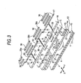
- Fig. 3 is a partially exploded perspective view illustrating the cavity unit.
- Fig. 4 is a partially enlarged sectional view illustrating the cavity unit.
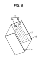
- Fig. 5 is a diagram illustrating formation of a first subunit of the cavity unit.
- Fig. 6 is a partially sectional view illustrating a recording head.
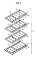
- Fig. 7 is a diagram illustrating formation of a second subunit of the cavity unit.
- Fig. 8 is a perspective view illustrating an inkjet printer according to a second embodiment.
- Fig. 9 is a perspective view illustrating a head holder as viewed from the bottom surface side of a head unit.
- Fig. 10 is an exploded perspective view illustrating a head unit.
-
- Hereinafter, embodiments of the invention will be described with reference to the accompanying drawings.
- As shown in Fig. 1, the inkjet printer according to this embodiment includes a recording unit 1, which is provided into a main frame (not shown) , for ejecting ink onto a printing paper as a recording medium to record images. The inkjet printer serves as a printer of a multi-function device (MFD) having, for example, function as a copier, scanner, facsimile, etc.
- The recording unit 1 includes a
head unit 53 constituting a carriage slidably reciprocating on horizontal plate-shaped guide rails - As shown in Fig. 1, the
head unit 53 includes ahead holder 54, an inkjet recording head (hereinafter referred to as a recording head) and a damper device 55 (see Fig. 6) . Thehead holder 54 has a substantially box-shaped main-body portion 54a and a connectingsupport piece 54b protruding toward downstream of the paper conveyance direction (a direction indicated by arrow A in Fig. 1) from the main-body portion 54a. Theinkjet recording head 10 is fixed to face a paper, at a lower surface side of abottom plate 54c of thehead holder 54. Thedamper device 55 is fixed to an upper side of thebottom plate 54c. - The inkjet printer has individual ink tanks (not shown), which are provided in a main frame of a main body, including tanks for yellow ink (Y), magenta ink (M), cyan ink (C), and black ink (Bk) serving as ink supply sources for full-color recording. The ink is supplied from individual ink tanks to the
recording head 10 through individual ink supply pipes (not shown) such as ink tubes and thedamper device 55. - As shown in Figs. 2 and 4, the
recording head 10 includes acavity unit 20 having a plurality ofnozzle holes 4, which are arranged on a surface (front surface) exposed to outside, for ejecting the ink onto a printing paper; a plate-shapedpiezoelectric actuator unit 23 laminated and fixed on a rear side of thecavityunit 20; and a flexibleflat cable 24 laminated and fixed on a rear side of thepiezoelectric actuator unit 23 for connection with external devices. Since Fig. 2 is a diagram illustrating therecording head 10 as viewed from the nozzle surface (front surface) side, thepiezoelectric actuator unit 23 is disposed on a lower side of thecavity unit 20 while the nozzle surface is positioned on an upper side. However, the nozzle surface is placed on a lower side when therecording head 10 is actually mounted on the inkjet printer. - As shown in Fig. 2, the
cavity unit 20 has a laminated structure including a total of eight plates, that is, anozzle plate 11, aspacer plate 12, adamper plate 13, twomanifold plates supply plate 15, abase plate 16, and acavity plate 17, laminated and joined on each other with adhesive agent. - In this embodiment, each of the
plates 11 to 17 has a thickness of about 50 to 150 µm. Thenozzle plate 11 is made of a substantially transparent synthetic resin such as polyimide, while theother plates 12 to 17 are made of a substantially opaque material such as metal (e.g., a nickel alloy steel including 42% of nickel) or a silicone. In thenozzle plate 11, the nozzles holes 4 for ejecting ink are defined to have an extremely small diameter (about 25 µm in this embodiment) and to be arranged at predetermined minute intervals. The nozzle holes 4 are arranged along a long-side direction (X direction) of the nozzle plate to form five rows in a zigzag manner. - Also, as shown in Fig. 3, in the
cavity plate 17, a plurality ofpressure chambers 36 are arranged along a long-side direction (the X direction) of the cavity plate to form five rows in a zigzag manner. In this embodiment, each of thepressure chambers 36 is formed in an elongated rectangle shape as viewed in a plan view. Thepressure chambers 36 passes through thecavity plate 17 so that its longitudinal direction extends in a short-side direction (Y direction) of thecavity plate 17. Also, oneend portions 36a thereof in the longitudinal direction communicate with the nozzle holes, and theother end portions 36b communicate withcommon ink chamber 7, which will be described later. - The endportions 36 a of the
pressure chambers 36 communicate with therespective nozzle holes 4 of thenozzle plate 11 through communication holes 37, which have a minute diameter and are formed in a similar zigzag manner to pass through thesupply plate 15, thebase plate 16, the twomanifold plates damper plate 13, and thespacer plate 12. - The
base plate 16 adjacent to a lower surface of thecavity plate 17 defines through-holes 38 at a position corresponding to theother end portions 36b of therespective pressure chambers 36, in order to connect to theother end portions 36b. - The
supply plate 15 adjacent to a lower surface of thebase plate 16 definesconnection flow path 40 for supplying the ink from thecommon ink chamber 7 to therespective pressure chambers 36. Each of theconnection flow path 40 has an inlet hole to which the ink is introduced from thecommon ink chamber 7, an outlet hole opened to the pressure chamber 36 (the through-holes 38), and a flow restricting portion between the inlet and outlet holes. The flow restricting portion has a small sectional area to have the largest flow resistance of the ink in the connection flow path. - The two
manifold plates common ink chambers 7 along the long-side direction (X direction) thereof. The common ink chambers are formed to pass through the entire thickness of each of the twomanifold plates manifold plates supply plate 15, and covering a lower surface thereof (an upper surface in Fig. 2) with thedamper plate 13. Eachcommon ink chamber 7 elongates in a direction substantially parallel to the rows of the pressure chambers 36 (the direction of the rows of the nozzle holes 4) while partially overlapping thepressure chambers 36, as viewed in a direction perpendicular to the laminated direction of each plate. - As shown in Figs. 3 and 4, the
damper plate 13 adjacent to a lower surface of themanifold plate 14a definesdamper chambers 45 recessed on a lower surface thereof so that thedamper chambers 45 are isolated from thecommon ink chamber 7. As shown in Fig. 2, the position and shape ofrespective damper chambers 45 are identical with those of respectivecommon ink chambers 7. Since thedamper plate 13 is made of elastically deformable metal, a sheet-shaped ceiling portion on an upper side of thedamper chamber 45 can freely oscillate toward thecommon ink chamber 7 and toward thedamper chamber 45. Even though pressure variation generated in thepressure chamber 36 upon ejecting ink is transmitted to thecommon ink chamber 7, the pressure variation can be damped or absorbed by an elastic deformation of the ceiling portion, thereby being prevented from crosstalk transmitting the pressure variation toother pressure chambers 36. - In addition, as shown in Fig. 2, each of the
cavity plate 17, thebase plate 16, and thesupply plate 15 defines fourink supply ports 47 is formed to pass therethrough at an end portion on one short-side side so that positions of theink supply ports 47 correspond to each other vertically. Outlet openings of thedamper device 55 communicate with one end portions of the respectivecommon ink chambers 7 through theink supply ports 47. The fourink supply ports 47 are denoted by 47a, 47b, 47c, and 47d from the right side of Fig. 2, respectively. - In ink flow paths from the
ink supply ports 47 to the nozzle holes 4, after ink supplied from thedamper device 55 is supplied from theink supply ports 47 to thecommon ink chambers 7 serving as ink supply channels, the ink is distributed to therespective pressure chambers 36 via theconnection flow paths 40 of thesupply plate 15 and the through-holes 38 of thebase plate 16 as shown in Fig. 3. As described later, then, the ink is supplied from inside of each of thepressure chambers 36 to thenozzle hole 4 corresponding to thepressure chamber 36 via the corresponding communicatingholes 37, by activation of the piezoelectric actuator unit 2. - In this embodiment, as shown in Fig. 2, the four
ink supply ports 47 are defined, while the fivecommon ink chambers 7 are defined. Here, only theink supply port 47a for supplying black ink is connected to twocommon ink chambers ink supply port 47a. This is because the black ink is more frequently used than the other color inks. Yellow, magenta, and cyan inks are supplied to the otherink supply ports - Also, the
base plate 16 definescirculation grooves 50 for testing, which are opened to a boundary face with thecavity plate 17 while being opened toward a end face on a short-side side of thebase plate 16. During the manufacturing process, a leak test is performed using thecirculation grooves 50 for testing to inspect poor sealing between thepressure chambers 36 due to poor adhesion between thecavity plate 17 and thebase plate 16. - Also, the
cavity unit 20 has aninformation recording portion 8, in which in which unique information of therecording head 10 is recorded, so that theinformation recording portion 8 is readable from outside on thenozzle plate 11 side. In this embodiment, theinformation recording portion 8 is disposed on a surface of thespacer plate 12, which faces thenozzle plate 11. As shown in Figs. 2 and 5, thenozzle plate 11 is adhered to thespacer plate 12 to cover theinformation recording portion 8. - The
information recording portion 8 is disposed outside a region where the plural communicatingholes 37 form the rows in thespacer plate 12, and is disposed at a position corresponding to a position of theink supply ports 47. In other words, theinformation recording portion 8 at least partially overlaps theink supply ports 47 when viewed in a plan view. Theink supply ports 47 are disposed outside a region corresponding to the rows formed of the nozzle holes 4 (communicating holes 37) . Accordingly, theink supply ports 47 occupy relatively wide region on an end portion on one short-side side of thecavity unit 20. Also, a hole process is not applied to thespacer plate 12 at a position corresponding to theinky supplyports 47. Accordingly, since theinformation recording portion 8 is disposed at the position described above, a wide are can be secured for theinformation recording portion 8. - In the
information recording portion 8, afirst code portion 8a and asecond code portion 8b are provided. In thefirst code portion 8a, for example, a QR code or another two-dimensional code is recorded. Thefirst code portion 8a is read by a known two-dimensional code scanner. Thesecond code portion 8b is provided supplementarily so that when it is impossible to read thefirst code portion 8a, an operator can read from thesecond code portion 8b the same contents as thefirst code portion 8a with eyes. Since the two-dimensional code is adopted in theinformation recording portion 8, more information can be recorded in a small area. Here, theinformation recording portion 8 has a manufacturing serial number recorded thereon serving as unique information of therecording head 10. Measurement data and various data in each process in manufacturing therecording head 10 are stored in an external device (which will be described below) so as to be associated with the serial number. In addition, thefirst code portion 8a may contain more information as well as the serial number. Further, thesecond code portion 8b may be omitted. Also, thefirst code portion 8a is not limited to the two-dimensional code, but may be a bar code or hologram. - Also, the information recorded in the
information recording portion 8 is formed as concavity and convexity. Here, the information is inscribed on the plate using a laser marker, etc. As described above, since thenozzle plate 11 is made of the substantially transparent material, theinformation recording portion 8 covered with thenozzle plate 11 is readable from the outside. Since thespacer plate 12 having theinformation recording portion 8 is covered with the substantiallytransparent nozzle plate 11, theinformation recording portion 8 is readable while thenozzle plate 11 protects theinformation recording portion 8 from contamination. - On the other hand, like a piezoelectric actuator unit disclosed in JP-A-Hei.4-341853, the
piezoelectric actuator unit 23 has a structure in which a plurality of piezoelectric sheets are laminated on each other (not shown). Individual electrodes having a narrow width are formed on an upper surface (i.e., surface having a relatively large width) of each even-numbered one of the piezoelectric sheets, which have thickness of about 30 µm, as counted from the lowermost one. The individual electrodes are formed at positions corresponding to thepressure chambers 36, respectively. The individual electrodes extend in the long-side direction (X direction) to form rows. A common electrode, which is common to the plurality ofpressure chambers 36, is formed on an upper surface (i.e., surface having a relatively large width) of each odd-numbered one of the piezoelectric sheets as counted from the lowermost one. On an upper surface of the top sheet, surface electrodes electrically connected to the individual electrodes and a surface electrode electrically connected to the common electrodes are formed as asurface electrode 48. - An adhesive agent sheet (not-shown) made of a synthetic resin material having ink nonpermeability is attached onto the entire lower surface of the sheet-shaped piezoelectric actuator unit 23 (i.e., the wide width surface opposed to the pressure chambers 36) in advance. Then, the
actuator unit 23 is bonded and fixed to thecavity unit 20 so that the individual electrodes are located at positions corresponding to thepressure chambers 36 of thecavity unit 20. Further, the flexible flat cable 24 (see Fig. 4) is laid and pressed onto the upper surface of theactuator unit 23. Thereby, electrically conductive wire patterns (not shown) of the flexibleflat cable 24 are electrically connected to thesurface electrodes 48, respectively. - In the first embodiment thus configured, as shown in Fig. 7, plural plates of the same type are connected to each other in plan view. More specifically, plural plates of each type are arranged in a
frame 210 through connectingpieces 211 having a narrow width. Openings such as the pressure chamber and the communicating hole are formed in each plate by press machining, etching, or laser machining. At this time, the two-dimensional code (thefirst code portion 8a) and thesecond code portion 8b, which serve as theinformation recording portion 8, are inscribed by the laser machining in a surface of thespacer plate 12 facing thenozzle plate 11. Sinceplural spacer plates 12 are arranged in theframe 210, it is easy to attach a serial number serving as theinformation recording portion 8. - As shown in Fig. 5, a
transparent plate material 11a serving as thenozzle plate 11 is adhered and fixed to each of thespacer plates 12 arranged in theframe 210 to cover theinformation recording portion 8. Thereafter, like a knownmethod disclosed in JP-A-Hei . 11-147316, a laser beam is irradiated to thespacer plate 12 and thenozzle plate 11, which are laminated on each other, through the communicatingholes 37 from thespacer plate 12 side, thereby to forming the plural nozzle holes in the nozzle plate. - Also, a subunit 22 (see Fig. 2) is formed by laminating the
damper plate 13, themanifold plates supply plate 15, thebase plate 16, and thecavity plate 17, which are arranged in theframes 210, respectively, and bonding and integrating those plates. Thesubunit 22 is laminated on a subunit 21 (see Fig. 2) in which the spacer plate and the nozzle plate have been integrated, and those subunits are bonded and are integrated together, thereby forming thecavity unit 20. The bonding is performed utilizingpositioning holes frame 210 shown in Fig. 7. After the bonding, the connectingpieces 211 are cut off to separate individual cavity units from each other. - At a time where the
cavity unit 20 has been formed, machining accuracies such as diameters of the nozzle holes 4 or a hole pitch flow path resistance, are measured. Criterion for classifying the machining accuracies into plural levels (ranks) in accordance with finishing state of thecavity unit 20 is determined in advance. The measurement values and/or classified result of eachcavity unit 20 are input into an external computer and stored in its storage device in association with the serial number recorded on theinformation recording portion 8. - Next, the
cavity unit 20 is bonded with thepiezoelectric actuator unit 23. Thepiezoelectric actuator unit 23 has also been assigned a lot number in advance, and been inspected to check piezoelectric characteristic thereof and classified into the levels (ranks). Further, an optimum combination for ejecting ink between classifications of the measurement values of thepiezoelectric actuator units 23 and classifications of the measurement values of thecavity units 20 is determined in advance, and an optimum activating voltage for each combination is also determined in advance. Accordingly, upon bonding, acavity unit 20 suitable for eachpiezoelectric actuator unit 23 can be selected on the basis of the unique information (serial number) recorded in theinformation recording section 8 thereof with reference to data. - Also, the machining accuracies of the nozzle holes 4 are inspected with using the
cavity unit 20 along prior to bonding thecavity unit 20 and thepiezoelectric actuator unit 23 together. Therefore, it is possible to remove only adefective cavity unit 20 without wasting a goodpiezoelectric actuator unit 23 if the nozzle hole formation has been made poorly. - The flexible
flat cable 24 is further bonded to thecavity unit 20 and thepiezoelectric actuator unit 23 to form therecording head 10. As described above, since the optimum activating voltage for therecording head 10 varies depending on the combination of thecavity unit 20 and thepiezoelectric actuator unit 23, the activating voltage of eachrecording head 10 is stored in the external storage device so as to be associated with the unique information of theinformation recording portion 8. When therecording head 10 is mounted onto a main body of an inkjet printer, the activating voltage stored in the storage device is referred to on the basis on the unique information, and the voltage is set to an output voltage of the main body of the inkjet printer. - Also, when the
recording head 10 is separated from a frame of themainbodytobe replaced with newone, anoptimumactivating voltage for thenew recording head 10 can be identified based on the unique information recorded in theinformation recording portion 8. Therefore, an output voltage to therecording head 10 can be immediately changed. - In the first embodiment, the
information recording portion 8 is disposed on thespacer plate 12 used for forming the nozzle holes 4, and the unique information for identifying the respective recording heads is attached in an early stage of the manufacturing process of therecording head 10. Therefore, it is possible to always collect and store data so as to be associated with the unique information. Accordingly, the unique information can be utilized in the manufacturing process for quality management such as removal of defective products or combination of optimum parts. - Also, as shown in Fig. 6, the
recording head 10 includes various elements such as abottom plate 54c of the head holder and adamper device 55, on an opposite surface to a surface from which thenozzle hole 4 is exposed. Accordingly, since theinformation recording portion 8 is arranged to be readable from outside of the surface from which thenozzle hole 4 is exposed, theinformation recording portion 8 can be easily read without being obstructed by another element. - Also, since the
information recording portion 8 is arranged at a position covered with thenozzle plate 11, even if thenozzle plate 11 is contaminated with ejected ink or particles of paper, those ink and particles are easily removed with using a known wiper member. Also, although theinformation recording portion 8 is implemented by minute concavity and convexity, those ink or particles of paper will not be retained in theinformation recording portion 8 to contaminate a recording medium. - Also, when the
recording head 10 is broken down, it is possible to easily find out its manufacturing history based on the unique information of theinformation recording portion 8. - In addition, since the
information recording portion 8 is directly inscribed on the plate, theinformation recording portion 8 can be formed even in a minute element such as therecording head 10. Accordingly, workability is more excellent than the conventional operation of pasting a label. - Next, a second embodiment of the inventionwill be described with reference to the drawings. The same as the elements of the first embodiment are denoted by the same reference numerals and detailed description thereof will be omitted herein.
- While the ink is supplied from the ink supply source provided in a main body to the
recording head 10 provided on a carriage (headunit 53) through an ink supplypipe in the first embodiment, therecording head 10 and anink cartridge 61 serving as an ink supply source are mounted on acarriage 64 in the second embodiment. - As shown in Fig. 8, an
inkjet printer 100 according to the second embodiment includes theink cartridge 61 filled with four color inks, for example, including cyan, magenta, yellow, and black; ahead unit 63 for printing an image on a paper 62 (recording medium) 62; thecarriage 64 on which theink cartridge 61 and thehead unit 63 are mounted; a drivingunit 65 for reciprocating thecarriage 64 in a direction (main-scanning direction, y-direction) perpendicular to a conveyance direction (sub-scanning direction, x-direction) of thepaper 62; aplaten roller 66 extending in the reciprocating direction of thecarriage 64 and being arranged to face thehead unit 63; and apurge unit 67. - The driving
unit 65 includes acarriage shaft 71, which is disposed on a lower side of thecarriage 64 and extends in parallel to theplaten roller 66; aguide plate 72, which is disposed on an upper side of thecarriage 64 and extends in parallel to thecarriage shaft 71; twopulleys carriage shaft 71 and theguide plate 72 and arranged on both end portions of thecarriage shaft 71; and atiming belt 75, which is wound around the twopulleys carriage 64, which is joined with thetiming belt 75, can reciprocate linearly while being supported by thecarriage shaft 71 and theguide plate 72, by a driving force transmitted from onepulley 73 rotated by amotor 76. Thepaper 62 conveyed in the X-direction (sub-scanning direction) from a paper feeder (not shown) is introduced into a gap between theplaten roller 66 and thehead unit 63. Subsequently, the ink is ejected from thehead unit 63 onto thepaper 62, thereby printing an image on thepaper 62. - The
purge unit 67 is disposed to face thehead unit 63 when thehead unit 63 is located at a recovery position. Thepurge unit 67 includes apurge cap 81, which abuts against the plural nozzle holes 4 of thehead unit 63 to cover the nozzle holes 4; apump 82; acam 83; and anink reservoir unit 84. When thehead unit 63 is located at the recovery position, defective ink containing bubbles or the like within thehead unit 63 is absorbed by thepump 82 by driving thecam 83, and is collected in theink reservoir unit 84. Also, thepurge unit 67 further includes awiper member 86 for cleaning a nozzle surface of thehead unit 63, and acap 85 for covering the nozzle holes 4 when thecarriage 64 returns to a rest position. - As shown in Fig. 9, the
head unit 63 includes two recording heads 10 and 10 provided parallel to each other on a lower surface side (an upper side in Fig. 9) of abottom plate 154a of thehead holder 154; and a protectingcover 87 covering the recording heads 10 and 10. The protectingcover 87 has a box shape and defines anopening window 87a allowing the rows of the nozzle holes 4 on a surface of eachrecording head 10 to be exposed. The protectingcover 87 is fixed to front faces of the recording heads 10, 10 and thehead holder 154. - As shown in Fig. 10, the
head holder 154 has a box shape with its top surface opened. The fourink cartridges 61 serving as the ink supply sources are detachably mounted on opening portions of thehead holder 154 from thereabove . Thehead holder 154 defines in a side portion of abottom plate 154a thereof a supply passage 90 (being designated as 90a to 90d, respectively) , which is capable of connecting to an ink discharge portion (not shown) of each of the ink cartridges 61 (see Fig. 10) . Further, holes 89a and 89b are defined through thebottom plate 154a to serve as holes used for injecting an adhesive agent to fix the recording head. - Like the recording head according to the first embodiment, the
recording head 10 according to the second embodiment is configured so that thecavity unit 20 in which eight plates are laminated on each other, thepiezoelectric actuator unit 23, and the flexibleflat cable 24 are laminated and fixed. However, unlike the first embodiment, asingle recording head 10 has tow rows ofnozzle holes 4 and twoink supply ports 47 so that two color inks are ejected separately. Therefore, the two recording heads 10, 10 are mounted on onehead holder 154 to correspond to the four color inks. The total of four ink supply ports 47 (47a to 47d) are respectively connected to thesupply passages 90a to 90d of thehead holder 154, respectively so that the ink is supplied from theink cartridge 61 to the nozzle holes 4. - As shown in Fig. 9, in the
recording head 10 according to the second embodiment, theinformation recording portion 8 is disposed to be readable from the outside on thenozzle plate 11 side. Like the first embodiment, theinformation recording portion 8 is inscribed on a surface of thespacer plate 12, which faces thenozzle plate 11, and is covered with thenozzle plate 11 made of a substantially transparent material (thenozzle plate 11 and thespacer plate 12 are not shown in Figs. 8 to 10) . Also, in order to secure a predetermined area for recording information, theinformation recording portion 8 is disposed outside a region corresponding to the rows of the plural communicatingholes 37 in thespacer plate 12 and is disposed at a position corresponding to a connection position between theink supply ports 47 and thesupply passage 90. In other words, theinformation recording portion 8 at least partially overlaps the connection position when viewed in a plan view. - In addition, in the second embodiment, while only the
first code portion 8a is illustrated as theinformation recording portion 8, thesecond code portion 8b may be provided together with thefirst code portion 8a. - Even in configuration in which a plurality of recording heads 10 are mounted on a single inkjet printer as described in the second embodiment, the recording heads 10 are individually managed based on the unique information recorded on the
information recording portions 8, and various measured values or data stored from an early stage of the manufacturing process can be always referred to as with the first embodiment. All of the other advantages are the same as those in the first embodiment. - In addition, while the
information recording portion 8 is formed as the minute concavity and convexity in the above-mentioned first and second embodiments, the information recording portion 8may be provided in the form of an IC chip storing unique information, or a small-sized sticker in which the unique information is printed so long as those IC chip and sticker are readable from outside. - Also, while the
information recording portion 8 has been provided in the spacer plate 12 (the second plate from the plate defining the nozzle holes 4) adjacent to thenozzle plate 11, the invention is not limited thereto. Theinformation recording portion 8 may be disposed on another plate so long as theinformation recording portion 8 is readable from outside of the surface from which the nozzle holes 4 are exposed. - The
information recording portion 8 may be disposed on the surface of thenozzle plate 11, which is exposed to the outside. If theinformation recording portion 8 were made of a sticker, it would be impossible to wipe ink soaking into the sticker even with using a wiper member. In the embodiments, theinformation recordingportion 8 is formed as minute concavity and convexity by etching or the like. Therefore, even when the ink contaminates theinformation recording portion 8 disposed on the exposed surface of thenozzle plate 11, it is possible to remove (wipe) the ink adhered to theinformation recording portion 8, for example, by using the wiping member. In this case, thenozzle plate 11 is made of a substantially opaque material such as metal or silicon, instead of the substantially transparent material. - In addition, while the
recording head 10 has been manufactured by separately forming the first subunit 21 and thesecond subunit 22, combining the first andsecond subunit 21 and 22 together to form thecavity unit 20, and further bonding thepiezoelectric actuator unit 23 with thecavity unit 20, therecording head 10 may be manufactured using a different combination and sequence in bonding.
Claims (19)
- An inkjet recording head comprising:a plurality of plates (11, 12, 13, 14a, 14b, 15, 16, 17) bonded to each other, the plates (11, 12, 13, 14a, 14b, 15, 16, 17) including a first plate (11) defining in one surface thereof a plurality of nozzle holes (4) through which ink is ejected to a recording medium, the one surface of the first plate (11) exposed to an outside; andan information recording portion (8) in which unique information (8a, 8b) of the inkjet recording head is recorded, the information recording portion (8) disposed so as to be readable from the outside on a one-surface side.
- The inkjet recording head according to claim 1, wherein:the first plate is substantially transparent;the plurality of plates further include an opaque second plate defining a plurality of communication holes communicating with the nozzle holes;the information recording portion is disposed on the second plate; andthe first plate is laminated on the second plate to cover the information recording portion.
- The inkjet recording head according to claim 2, wherein concavity and convexity are formed as the unique information in the information recording portion disposed on the second plate.
- The inkjet recording head according to any one of claims 2 to 3, wherein the information recording portion is disposed outside a region where the communication holes form rows.
- The inkjet recording head according to any one of claims 2 to 4, wherein:the first plate is made of a synthetic resin; andthe second plate is made of one of silicon and metal.
- The inkjet recording head according to claim 1, wherein:the first plate is substantially opaque; andthe information recording portion is disposed on the one surface of the first plate.
- The inkjet recording head according to claim 6, wherein concavity and convexity are formed as the unique information in the information recording portion disposed on the first plate.
- The inkjet recording head according to any one of claims 6 to 7, wherein the information recording portion is disposed outside a region where the nozzle holes form rows.
- The inkjet recording head according to any one of claims 1 to 8, wherein the information recording portion includes at least one of serial number, bar code, two-dimensional code, and hologram.
- The inkjet recording head according to any one of claims 1 to 9, wherein:the one surface of the first plate is identical with one surface of the inkjet recording head, which is exposed to the outside;the other surface of the inkjet recording head defines therein an ink supply port through which the ink supplied to the nozzle holes are flown from an ink supply source; andthe information recording portion is disposed at a position corresponding to a position of the ink supply port.
- The inkjet recording head according to claim 10, wherein when viewed in a plan view, the information recording portion at least partially overlaps the ink supply port.
- The inkjet recording head according to any one of claims 10 to 11, further comprising:an ink supply channel extending from the ink supply port along a direction of a row formed of the nozzle holes, wherein:the ink supply port is disposed outside a region corresponding to the row formed of the nozzle holes.
- A head unit comprising:an inkjet recording head (10) including a plurality of plates (11, 12, 13, 14a, 14b, 15, 16, 17) bonded to each other, the plates (11, 12, 13, 14a, 14b, 15, 16, 17) including a first plate (11) defining in one surface thereof a plurality of nozzle holes (4) through which ink is ejected to a recording medium, the one surface of the first plate (11) exposed to an outside; anda head holder (154) onto which the inkjet recording head (10) is mounted so that the one surface of the first plate (11) faces the recording medium, the head holder (154) capable of moving in parallel to the recording medium, wherein:the inkjet recording head (10) includes an information recording portion (8) in which unique information (8a, 8b) of the inkj et recording head is recorded, the information recording portion (8) disposed so as to be readable from the outside on a one-surface side
- The head unit according to claim 13, wherein
the first plate is substantially transparent;
the plurality of plates further include an opaque second plate defining a plurality of communication holes communicating with the nozzle holes;
the information recording portion is disposed on the second plate; and
the first plate is laminated on the second plate to cover the information recording portion. - The head unit according to claim 14, wherein concavity and convexity are formed as the unique information in the information recording portion disposed on the second plate.
- The head unit according to claim 13, wherein:the first plate is substantially opaque; andthe information recording portion is disposed on the one surface of the first plate.
- The head unit according to claim 16, wherein concavity and convexity are formed as the unique information in the information recording portion disposed on the second plate.
- The head unit according to any one of claims 13 to 17, wherein:the head holder comprises an ink supply path that introduces the ink to be supplied to the nozzle holes, from an ink supply source to the inkjet recording head;a connection portion between the ink supply path and the inkjet recording head is disposed outside a region corresponding to a row formed of the nozzle holes; andthe information recording portion is disposed at a position corresponding to the connection portion.
- The head unit according to claim 18, when viewed in aplanview, the information recording portion at least partially overlaps the connection position.
Applications Claiming Priority (2)
| Application Number | Priority Date | Filing Date | Title |
|---|---|---|---|
| JP2004138454A JP4235820B2 (en) | 2004-05-07 | 2004-05-07 | Ink jet recording head, head unit, and method of manufacturing ink jet recording head |
| JP2004138454 | 2004-05-07 |
Publications (2)
| Publication Number | Publication Date |
|---|---|
| EP1593517A1 true EP1593517A1 (en) | 2005-11-09 |
| EP1593517B1 EP1593517B1 (en) | 2008-03-19 |
Family
ID=34936217
Family Applications (1)
| Application Number | Title | Priority Date | Filing Date |
|---|---|---|---|
| EP05009911A Expired - Lifetime EP1593517B1 (en) | 2004-05-07 | 2005-05-06 | Inkjet recording head and head unit |
Country Status (5)
| Country | Link |
|---|---|
| US (1) | US7344229B2 (en) |
| EP (1) | EP1593517B1 (en) |
| JP (1) | JP4235820B2 (en) |
| AT (1) | ATE389541T1 (en) |
| DE (1) | DE602005005379T2 (en) |
Cited By (1)
| Publication number | Priority date | Publication date | Assignee | Title |
|---|---|---|---|---|
| CN101823369A (en) * | 2009-03-02 | 2010-09-08 | 兄弟工业株式会社 | Liquid ejection head, recording apparatus including liquid ejection head, and manufacturing method thereof |
Families Citing this family (12)
| Publication number | Priority date | Publication date | Assignee | Title |
|---|---|---|---|---|
| JP4831325B2 (en) * | 2006-07-13 | 2011-12-07 | セイコーエプソン株式会社 | Liquid ejecting head manufacturing method, liquid ejecting head, and liquid ejecting apparatus |
| JP4363458B2 (en) * | 2007-05-10 | 2009-11-11 | セイコーエプソン株式会社 | Liquid ejecting head unit and liquid ejecting apparatus |
| JP2010137487A (en) * | 2008-12-15 | 2010-06-24 | Seiko Epson Corp | Liquid discharge head, liquid discharge head unit, and liquid discharge device |
| JP4720917B2 (en) * | 2009-03-02 | 2011-07-13 | ブラザー工業株式会社 | LIQUID DISCHARGE HEAD, RECORDING DEVICE MANUFACTURING METHOD INCLUDING THE SAME, LIQUID DISCHARGE HEAD AND RECORDING DEVICE |
| US8342659B2 (en) * | 2009-08-25 | 2013-01-01 | Canon Kabushiki Kaisha | Liquid discharge head and method for manufacturing the same |
| JP2012020422A (en) * | 2010-07-12 | 2012-02-02 | Seiko Epson Corp | Liquid ejecting head, liquid ejecting head unit and liquid ejecting apparatus |
| JP2012121282A (en) * | 2010-12-10 | 2012-06-28 | Seiko Epson Corp | Liquid ejecting apparatus |
| JP5750753B2 (en) * | 2011-01-11 | 2015-07-22 | セイコーエプソン株式会社 | Liquid ejecting head and liquid ejecting apparatus |
| JP5668482B2 (en) | 2011-01-13 | 2015-02-12 | セイコーエプソン株式会社 | Liquid ejecting head and liquid ejecting apparatus |
| JPWO2017130695A1 (en) * | 2016-01-29 | 2018-11-15 | コニカミノルタ株式会社 | Ink jet drive device and ink jet drive method |
| JP7877045B2 (en) * | 2022-04-21 | 2026-06-22 | キヤノン株式会社 | Recording element substrate and method for manufacturing the same |
| KR102881039B1 (en) * | 2023-02-10 | 2025-11-04 | 서울대학교산학협력단 | Microdroplet discharge device |
Citations (8)
| Publication number | Priority date | Publication date | Assignee | Title |
|---|---|---|---|---|
| EP0389296A2 (en) * | 1989-03-24 | 1990-09-26 | Canon Kabushiki Kaisha | Ink jet head substrate and ink jet head having the same |
| JPH04341853A (en) | 1991-05-20 | 1992-11-27 | Brother Ind Ltd | piezoelectric inkjet printer head |
| JPH05159112A (en) | 1991-12-04 | 1993-06-25 | Canon Inc | Recorder |
| EP0775587A1 (en) * | 1995-11-21 | 1997-05-28 | Hewlett-Packard Company | Inkjet printhead alignment via measurement and entry |
| JPH09234861A (en) * | 1996-02-29 | 1997-09-09 | Copyer Co Ltd | Inkjet image forming apparatus |
| JPH11147316A (en) | 1997-11-17 | 1999-06-02 | Fujitsu Ltd | Method of manufacturing ink jet recording head and nozzle plate |
| US6053597A (en) | 1996-05-30 | 2000-04-25 | Ricoh Company, Ltd. | Ink jet recording apparatus and method for automatically changing recording operation mode when interchangeable recording head unit is replaced |
| US6478399B1 (en) | 1998-08-31 | 2002-11-12 | Seiko Epson Corporation | Printer and print head unit for same |
Family Cites Families (16)
| Publication number | Priority date | Publication date | Assignee | Title |
|---|---|---|---|---|
| US4829319A (en) * | 1987-11-13 | 1989-05-09 | Hewlett-Packard Company | Plastic orifice plate for an ink jet printhead and method of manufacture |
| JPH02128181U (en) * | 1989-03-30 | 1990-10-23 | ||
| US5402159A (en) | 1990-03-26 | 1995-03-28 | Brother Kogyo Kabushiki Kaisha | Piezoelectric ink jet printer using laminated piezoelectric actuator |
| JPH0843271A (en) | 1994-07-28 | 1996-02-16 | Teijin Bio Lab:Kk | Method for storing / transporting body fluid sample and storage container usable therefor |
| US5721573A (en) * | 1995-05-24 | 1998-02-24 | Hewlett-Packard Company | Cooldown timing system monitors inkjet cartridge ink levels |
| JP2755251B2 (en) * | 1996-05-10 | 1998-05-20 | 日本電気株式会社 | Marking device and marking method for electronic component |
| JP3371330B2 (en) * | 1998-08-31 | 2003-01-27 | セイコーエプソン株式会社 | Printer and print head unit therefor |
| JP2000248854A (en) * | 1999-02-26 | 2000-09-12 | Okamura Corp | Door with display function |
| JP2001129983A (en) * | 1999-11-09 | 2001-05-15 | Canon Inc | Ink jet recording apparatus and adjustment method thereof |
| JP2002137394A (en) * | 2000-08-24 | 2002-05-14 | Seiko Epson Corp | Two-dimensional code creation device and conversion code string creation device |
| US6464344B2 (en) * | 2000-12-27 | 2002-10-15 | Citizen Watch Co., Ltd. | Microstructured element and method for producing the same |
| JP2002273885A (en) * | 2001-01-12 | 2002-09-25 | Fuji Photo Film Co Ltd | Inkjet head |
| JP2002331668A (en) * | 2001-05-11 | 2002-11-19 | Canon Inc | Liquid ejection head |
| JP3687649B2 (en) * | 2002-01-15 | 2005-08-24 | セイコーエプソン株式会社 | Method for measuring natural vibration period of liquid ejecting head, natural vibration period measuring apparatus, liquid ejecting head, and liquid ejecting apparatus |
| US6994428B2 (en) * | 2002-05-21 | 2006-02-07 | Brother Kogyo Kabushiki Kaisha | Ink-jet printing head having a plurality of actuator units and/or a plurality of manifold chambers |
| JP4051541B2 (en) * | 2002-05-21 | 2008-02-27 | ブラザー工業株式会社 | Inkjet printer head |
-
2004
- 2004-05-07 JP JP2004138454A patent/JP4235820B2/en not_active Expired - Fee Related
-
2005
- 2005-05-04 US US11/122,184 patent/US7344229B2/en not_active Expired - Lifetime
- 2005-05-06 DE DE602005005379T patent/DE602005005379T2/en not_active Expired - Lifetime
- 2005-05-06 AT AT05009911T patent/ATE389541T1/en not_active IP Right Cessation
- 2005-05-06 EP EP05009911A patent/EP1593517B1/en not_active Expired - Lifetime
Patent Citations (8)
| Publication number | Priority date | Publication date | Assignee | Title |
|---|---|---|---|---|
| EP0389296A2 (en) * | 1989-03-24 | 1990-09-26 | Canon Kabushiki Kaisha | Ink jet head substrate and ink jet head having the same |
| JPH04341853A (en) | 1991-05-20 | 1992-11-27 | Brother Ind Ltd | piezoelectric inkjet printer head |
| JPH05159112A (en) | 1991-12-04 | 1993-06-25 | Canon Inc | Recorder |
| EP0775587A1 (en) * | 1995-11-21 | 1997-05-28 | Hewlett-Packard Company | Inkjet printhead alignment via measurement and entry |
| JPH09234861A (en) * | 1996-02-29 | 1997-09-09 | Copyer Co Ltd | Inkjet image forming apparatus |
| US6053597A (en) | 1996-05-30 | 2000-04-25 | Ricoh Company, Ltd. | Ink jet recording apparatus and method for automatically changing recording operation mode when interchangeable recording head unit is replaced |
| JPH11147316A (en) | 1997-11-17 | 1999-06-02 | Fujitsu Ltd | Method of manufacturing ink jet recording head and nozzle plate |
| US6478399B1 (en) | 1998-08-31 | 2002-11-12 | Seiko Epson Corporation | Printer and print head unit for same |
Non-Patent Citations (1)
| Title |
|---|
| PATENT ABSTRACTS OF JAPAN vol. 1998, no. 01 30 January 1998 (1998-01-30) * |
Cited By (2)
| Publication number | Priority date | Publication date | Assignee | Title |
|---|---|---|---|---|
| CN101823369A (en) * | 2009-03-02 | 2010-09-08 | 兄弟工业株式会社 | Liquid ejection head, recording apparatus including liquid ejection head, and manufacturing method thereof |
| CN101823369B (en) * | 2009-03-02 | 2012-11-21 | 兄弟工业株式会社 | Liquid ejection head, recording apparatus with the same, and manufacturing method thereof |
Also Published As
| Publication number | Publication date |
|---|---|
| EP1593517B1 (en) | 2008-03-19 |
| DE602005005379T2 (en) | 2009-04-23 |
| DE602005005379D1 (en) | 2008-04-30 |
| JP2005319645A (en) | 2005-11-17 |
| ATE389541T1 (en) | 2008-04-15 |
| US20050248627A1 (en) | 2005-11-10 |
| US7344229B2 (en) | 2008-03-18 |
| JP4235820B2 (en) | 2009-03-11 |
Similar Documents
| Publication | Publication Date | Title |
|---|---|---|
| US8348407B2 (en) | Liquid ejection head, liquid-droplet ejection device, and image forming apparatus | |
| CN109228654B (en) | Flow path member, liquid ejecting head, and liquid ejecting apparatus | |
| KR100190416B1 (en) | Ink jet recording head | |
| EP1593517B1 (en) | Inkjet recording head and head unit | |
| US7614719B2 (en) | Inkjet printer and inkjet head with modification of driving waveform data | |
| CN109228657B (en) | Liquid ejecting head and liquid ejecting apparatus | |
| KR20070073926A (en) | Liquid discharge head, liquid discharge device, and image forming device | |
| JPH10309804A (en) | Multi-cartridge printhead assembly for use in inkjet printing systems | |
| US20100328400A1 (en) | Liquid-ejection head unit and image forming apparatus | |
| US20110298872A1 (en) | Piezoelectric actuator, liquid ejection head, and image forming apparatus | |
| US20140218450A1 (en) | Liquid ejection head and image forming device | |
| US7407267B2 (en) | Liquid droplet ejection head and image forming apparatus | |
| JP2020093468A (en) | Liquid ejection head manufacturing method and machine learning device | |
| CN109228656B (en) | Flow path member, liquid ejecting head, and liquid ejecting apparatus | |
| US20030210305A1 (en) | Ink-jet head | |
| US7422315B2 (en) | Liquid ejection head and image forming apparatus comprising same | |
| CN109228658B (en) | Liquid ejecting head and liquid ejecting apparatus | |
| JP2005067130A (en) | Liquid ejecting head unit, manufacturing method thereof, and liquid ejecting apparatus | |
| JP4935994B2 (en) | Liquid ejecting head unit and liquid ejecting apparatus | |
| JP4363458B2 (en) | Liquid ejecting head unit and liquid ejecting apparatus | |
| CN109228655B (en) | Liquid ejecting head and liquid ejecting apparatus | |
| CN109228662B (en) | Liquid ejecting head and liquid ejecting apparatus | |
| JPH06297722A (en) | Cap and ink jet recording apparatus using the cap | |
| JPH09187947A (en) | Inkjet head having an ink supply mechanism, inkjet head cartridge, and inkjet device | |
| EP1880853B1 (en) | Method for producing a liquid-ejecting head by checking a quality thereof |
Legal Events
| Date | Code | Title | Description |
|---|---|---|---|
| PUAI | Public reference made under article 153(3) epc to a published international application that has entered the european phase |
Free format text: ORIGINAL CODE: 0009012 |
|
| AK | Designated contracting states |
Kind code of ref document: A1 Designated state(s): AT BE BG CH CY CZ DE DK EE ES FI FR GB GR HU IE IS IT LI LT LU MC NL PL PT RO SE SI SK TR |
|
| AX | Request for extension of the european patent |
Extension state: AL BA HR LV MK YU |
|
| 17P | Request for examination filed |
Effective date: 20051116 |
|
| AKX | Designation fees paid |
Designated state(s): AT BE BG CH CY CZ DE DK EE ES FI FR GB GR HU IE IS IT LI LT LU MC NL PL PT RO SE SI SK TR |
|
| 17Q | First examination report despatched |
Effective date: 20060626 |
|
| GRAP | Despatch of communication of intention to grant a patent |
Free format text: ORIGINAL CODE: EPIDOSNIGR1 |
|
| GRAS | Grant fee paid |
Free format text: ORIGINAL CODE: EPIDOSNIGR3 |
|
| GRAA | (expected) grant |
Free format text: ORIGINAL CODE: 0009210 |
|
| AK | Designated contracting states |
Kind code of ref document: B1 Designated state(s): AT BE BG CH CY CZ DE DK EE ES FI FR GB GR HU IE IS IT LI LT LU MC NL PL PT RO SE SI SK TR |
|
| REG | Reference to a national code |
Ref country code: GB Ref legal event code: FG4D |
|
| REG | Reference to a national code |
Ref country code: CH Ref legal event code: EP |
|
| REF | Corresponds to: |
Ref document number: 602005005379 Country of ref document: DE Date of ref document: 20080430 Kind code of ref document: P |
|
| REG | Reference to a national code |
Ref country code: IE Ref legal event code: FG4D |
|
| PG25 | Lapsed in a contracting state [announced via postgrant information from national office to epo] |
Ref country code: LT Free format text: LAPSE BECAUSE OF FAILURE TO SUBMIT A TRANSLATION OF THE DESCRIPTION OR TO PAY THE FEE WITHIN THE PRESCRIBED TIME-LIMIT Effective date: 20080319 Ref country code: FI Free format text: LAPSE BECAUSE OF FAILURE TO SUBMIT A TRANSLATION OF THE DESCRIPTION OR TO PAY THE FEE WITHIN THE PRESCRIBED TIME-LIMIT Effective date: 20080319 |
|
| PG25 | Lapsed in a contracting state [announced via postgrant information from national office to epo] |
Ref country code: AT Free format text: LAPSE BECAUSE OF FAILURE TO SUBMIT A TRANSLATION OF THE DESCRIPTION OR TO PAY THE FEE WITHIN THE PRESCRIBED TIME-LIMIT Effective date: 20080319 |
|
| NLV1 | Nl: lapsed or annulled due to failure to fulfill the requirements of art. 29p and 29m of the patents act | ||
| PG25 | Lapsed in a contracting state [announced via postgrant information from national office to epo] |
Ref country code: BE Free format text: LAPSE BECAUSE OF FAILURE TO SUBMIT A TRANSLATION OF THE DESCRIPTION OR TO PAY THE FEE WITHIN THE PRESCRIBED TIME-LIMIT Effective date: 20080319 Ref country code: SI Free format text: LAPSE BECAUSE OF FAILURE TO SUBMIT A TRANSLATION OF THE DESCRIPTION OR TO PAY THE FEE WITHIN THE PRESCRIBED TIME-LIMIT Effective date: 20080319 Ref country code: PL Free format text: LAPSE BECAUSE OF FAILURE TO SUBMIT A TRANSLATION OF THE DESCRIPTION OR TO PAY THE FEE WITHIN THE PRESCRIBED TIME-LIMIT Effective date: 20080319 |
|
| ET | Fr: translation filed | ||
| PG25 | Lapsed in a contracting state [announced via postgrant information from national office to epo] |
Ref country code: SE Free format text: LAPSE BECAUSE OF FAILURE TO SUBMIT A TRANSLATION OF THE DESCRIPTION OR TO PAY THE FEE WITHIN THE PRESCRIBED TIME-LIMIT Effective date: 20080619 Ref country code: SK Free format text: LAPSE BECAUSE OF FAILURE TO SUBMIT A TRANSLATION OF THE DESCRIPTION OR TO PAY THE FEE WITHIN THE PRESCRIBED TIME-LIMIT Effective date: 20080319 Ref country code: CZ Free format text: LAPSE BECAUSE OF FAILURE TO SUBMIT A TRANSLATION OF THE DESCRIPTION OR TO PAY THE FEE WITHIN THE PRESCRIBED TIME-LIMIT Effective date: 20080319 Ref country code: ES Free format text: LAPSE BECAUSE OF FAILURE TO SUBMIT A TRANSLATION OF THE DESCRIPTION OR TO PAY THE FEE WITHIN THE PRESCRIBED TIME-LIMIT Effective date: 20080630 Ref country code: PT Free format text: LAPSE BECAUSE OF FAILURE TO SUBMIT A TRANSLATION OF THE DESCRIPTION OR TO PAY THE FEE WITHIN THE PRESCRIBED TIME-LIMIT Effective date: 20080826 |
|
| PG25 | Lapsed in a contracting state [announced via postgrant information from national office to epo] |
Ref country code: RO Free format text: LAPSE BECAUSE OF FAILURE TO SUBMIT A TRANSLATION OF THE DESCRIPTION OR TO PAY THE FEE WITHIN THE PRESCRIBED TIME-LIMIT Effective date: 20080319 Ref country code: NL Free format text: LAPSE BECAUSE OF FAILURE TO SUBMIT A TRANSLATION OF THE DESCRIPTION OR TO PAY THE FEE WITHIN THE PRESCRIBED TIME-LIMIT Effective date: 20080319 |
|
| PG25 | Lapsed in a contracting state [announced via postgrant information from national office to epo] |
Ref country code: IS Free format text: LAPSE BECAUSE OF FAILURE TO SUBMIT A TRANSLATION OF THE DESCRIPTION OR TO PAY THE FEE WITHIN THE PRESCRIBED TIME-LIMIT Effective date: 20080719 Ref country code: MC Free format text: LAPSE BECAUSE OF NON-PAYMENT OF DUE FEES Effective date: 20080531 |
|
| PLBE | No opposition filed within time limit |
Free format text: ORIGINAL CODE: 0009261 |
|
| STAA | Information on the status of an ep patent application or granted ep patent |
Free format text: STATUS: NO OPPOSITION FILED WITHIN TIME LIMIT |
|
| PG25 | Lapsed in a contracting state [announced via postgrant information from national office to epo] |
Ref country code: DK Free format text: LAPSE BECAUSE OF FAILURE TO SUBMIT A TRANSLATION OF THE DESCRIPTION OR TO PAY THE FEE WITHIN THE PRESCRIBED TIME-LIMIT Effective date: 20080319 Ref country code: EE Free format text: LAPSE BECAUSE OF FAILURE TO SUBMIT A TRANSLATION OF THE DESCRIPTION OR TO PAY THE FEE WITHIN THE PRESCRIBED TIME-LIMIT Effective date: 20080319 |
|
| 26N | No opposition filed |
Effective date: 20081222 |
|
| PG25 | Lapsed in a contracting state [announced via postgrant information from national office to epo] |
Ref country code: IE Free format text: LAPSE BECAUSE OF NON-PAYMENT OF DUE FEES Effective date: 20080506 Ref country code: BG Free format text: LAPSE BECAUSE OF FAILURE TO SUBMIT A TRANSLATION OF THE DESCRIPTION OR TO PAY THE FEE WITHIN THE PRESCRIBED TIME-LIMIT Effective date: 20080619 |
|
| PG25 | Lapsed in a contracting state [announced via postgrant information from national office to epo] |
Ref country code: IT Free format text: LAPSE BECAUSE OF FAILURE TO SUBMIT A TRANSLATION OF THE DESCRIPTION OR TO PAY THE FEE WITHIN THE PRESCRIBED TIME-LIMIT Effective date: 20080319 |
|
| PG25 | Lapsed in a contracting state [announced via postgrant information from national office to epo] |
Ref country code: CY Free format text: LAPSE BECAUSE OF FAILURE TO SUBMIT A TRANSLATION OF THE DESCRIPTION OR TO PAY THE FEE WITHIN THE PRESCRIBED TIME-LIMIT Effective date: 20080319 |
|
| REG | Reference to a national code |
Ref country code: CH Ref legal event code: PL |
|
| PG25 | Lapsed in a contracting state [announced via postgrant information from national office to epo] |
Ref country code: LI Free format text: LAPSE BECAUSE OF NON-PAYMENT OF DUE FEES Effective date: 20090531 Ref country code: CH Free format text: LAPSE BECAUSE OF NON-PAYMENT OF DUE FEES Effective date: 20090531 |
|
| PG25 | Lapsed in a contracting state [announced via postgrant information from national office to epo] |
Ref country code: HU Free format text: LAPSE BECAUSE OF FAILURE TO SUBMIT A TRANSLATION OF THE DESCRIPTION OR TO PAY THE FEE WITHIN THE PRESCRIBED TIME-LIMIT Effective date: 20080920 Ref country code: LU Free format text: LAPSE BECAUSE OF NON-PAYMENT OF DUE FEES Effective date: 20080506 |
|
| PG25 | Lapsed in a contracting state [announced via postgrant information from national office to epo] |
Ref country code: TR Free format text: LAPSE BECAUSE OF FAILURE TO SUBMIT A TRANSLATION OF THE DESCRIPTION OR TO PAY THE FEE WITHIN THE PRESCRIBED TIME-LIMIT Effective date: 20080319 |
|
| PG25 | Lapsed in a contracting state [announced via postgrant information from national office to epo] |
Ref country code: GR Free format text: LAPSE BECAUSE OF FAILURE TO SUBMIT A TRANSLATION OF THE DESCRIPTION OR TO PAY THE FEE WITHIN THE PRESCRIBED TIME-LIMIT Effective date: 20080620 |
|
| REG | Reference to a national code |
Ref country code: FR Ref legal event code: PLFP Year of fee payment: 12 |
|
| REG | Reference to a national code |
Ref country code: FR Ref legal event code: PLFP Year of fee payment: 13 |
|
| REG | Reference to a national code |
Ref country code: FR Ref legal event code: PLFP Year of fee payment: 14 |
|
| PGFP | Annual fee paid to national office [announced via postgrant information from national office to epo] |
Ref country code: FR Payment date: 20190410 Year of fee payment: 15 |
|
| PGFP | Annual fee paid to national office [announced via postgrant information from national office to epo] |
Ref country code: GB Payment date: 20190501 Year of fee payment: 15 |
|
| GBPC | Gb: european patent ceased through non-payment of renewal fee |
Effective date: 20200506 |
|
| PG25 | Lapsed in a contracting state [announced via postgrant information from national office to epo] |
Ref country code: FR Free format text: LAPSE BECAUSE OF NON-PAYMENT OF DUE FEES Effective date: 20200531 Ref country code: GB Free format text: LAPSE BECAUSE OF NON-PAYMENT OF DUE FEES Effective date: 20200506 |
|
| PGFP | Annual fee paid to national office [announced via postgrant information from national office to epo] |
Ref country code: DE Payment date: 20240328 Year of fee payment: 20 |
|
| REG | Reference to a national code |
Ref country code: DE Ref legal event code: R071 Ref document number: 602005005379 Country of ref document: DE |