EP1592890B1 - A linear hydraulic motor and a reciprocating floor conveyor - Google Patents
A linear hydraulic motor and a reciprocating floor conveyor Download PDFInfo
- Publication number
- EP1592890B1 EP1592890B1 EP04706750A EP04706750A EP1592890B1 EP 1592890 B1 EP1592890 B1 EP 1592890B1 EP 04706750 A EP04706750 A EP 04706750A EP 04706750 A EP04706750 A EP 04706750A EP 1592890 B1 EP1592890 B1 EP 1592890B1
- Authority
- EP
- European Patent Office
- Prior art keywords
- cylinder
- hydraulic motor
- piston
- linear hydraulic
- pistons
- Prior art date
- Legal status (The legal status is an assumption and is not a legal conclusion. Google has not performed a legal analysis and makes no representation as to the accuracy of the status listed.)
- Expired - Lifetime
Links
- 239000012530 fluid Substances 0.000 claims description 56
- VYZAMTAEIAYCRO-UHFFFAOYSA-N Chromium Chemical compound [Cr] VYZAMTAEIAYCRO-UHFFFAOYSA-N 0.000 claims description 2
- 239000010935 stainless steel Substances 0.000 claims 1
- 238000007789 sealing Methods 0.000 description 6
- 230000000295 complement effect Effects 0.000 description 4
- 238000006073 displacement reaction Methods 0.000 description 4
- 239000000463 material Substances 0.000 description 4
- 229910001369 Brass Inorganic materials 0.000 description 3
- 239000004677 Nylon Substances 0.000 description 3
- 229910000831 Steel Inorganic materials 0.000 description 3
- 230000015572 biosynthetic process Effects 0.000 description 3
- 239000010951 brass Substances 0.000 description 3
- 238000005755 formation reaction Methods 0.000 description 3
- 229920001778 nylon Polymers 0.000 description 3
- 239000010959 steel Substances 0.000 description 3
- PXHVJJICTQNCMI-UHFFFAOYSA-N Nickel Chemical compound [Ni] PXHVJJICTQNCMI-UHFFFAOYSA-N 0.000 description 2
- 239000002131 composite material Substances 0.000 description 2
- 229910000838 Al alloy Inorganic materials 0.000 description 1
- 229910000669 Chrome steel Inorganic materials 0.000 description 1
- 239000004411 aluminium Substances 0.000 description 1
- XAGFODPZIPBFFR-UHFFFAOYSA-N aluminium Chemical compound [Al] XAGFODPZIPBFFR-UHFFFAOYSA-N 0.000 description 1
- 229910052782 aluminium Inorganic materials 0.000 description 1
- 230000003247 decreasing effect Effects 0.000 description 1
- 239000010720 hydraulic oil Substances 0.000 description 1
- 238000009434 installation Methods 0.000 description 1
- 239000007788 liquid Substances 0.000 description 1
- 238000000034 method Methods 0.000 description 1
- 229910052759 nickel Inorganic materials 0.000 description 1
- 239000004033 plastic Substances 0.000 description 1
- 229920003023 plastic Polymers 0.000 description 1
- 230000003014 reinforcing effect Effects 0.000 description 1
- 239000002023 wood Substances 0.000 description 1
Images





Classifications
-
- F—MECHANICAL ENGINEERING; LIGHTING; HEATING; WEAPONS; BLASTING
- F15—FLUID-PRESSURE ACTUATORS; HYDRAULICS OR PNEUMATICS IN GENERAL
- F15B—SYSTEMS ACTING BY MEANS OF FLUIDS IN GENERAL; FLUID-PRESSURE ACTUATORS, e.g. SERVOMOTORS; DETAILS OF FLUID-PRESSURE SYSTEMS, NOT OTHERWISE PROVIDED FOR
- F15B11/00—Servomotor systems without provision for follow-up action; Circuits therefor
- F15B11/08—Servomotor systems without provision for follow-up action; Circuits therefor with only one servomotor
- F15B11/12—Servomotor systems without provision for follow-up action; Circuits therefor with only one servomotor providing distinct intermediate positions; with step-by-step action
- F15B11/127—Servomotor systems without provision for follow-up action; Circuits therefor with only one servomotor providing distinct intermediate positions; with step-by-step action with step-by-step action
-
- B—PERFORMING OPERATIONS; TRANSPORTING
- B65—CONVEYING; PACKING; STORING; HANDLING THIN OR FILAMENTARY MATERIAL
- B65G—TRANSPORT OR STORAGE DEVICES, e.g. CONVEYORS FOR LOADING OR TIPPING, SHOP CONVEYOR SYSTEMS OR PNEUMATIC TUBE CONVEYORS
- B65G25/00—Conveyors comprising a cyclically-moving, e.g. reciprocating, carrier or impeller which is disengaged from the load during the return part of its movement
- B65G25/04—Conveyors comprising a cyclically-moving, e.g. reciprocating, carrier or impeller which is disengaged from the load during the return part of its movement the carrier or impeller having identical forward and return paths of movement, e.g. reciprocating conveyors
- B65G25/06—Conveyors comprising a cyclically-moving, e.g. reciprocating, carrier or impeller which is disengaged from the load during the return part of its movement the carrier or impeller having identical forward and return paths of movement, e.g. reciprocating conveyors having carriers, e.g. belts
- B65G25/065—Reciprocating floor conveyors
-
- F—MECHANICAL ENGINEERING; LIGHTING; HEATING; WEAPONS; BLASTING
- F15—FLUID-PRESSURE ACTUATORS; HYDRAULICS OR PNEUMATICS IN GENERAL
- F15B—SYSTEMS ACTING BY MEANS OF FLUIDS IN GENERAL; FLUID-PRESSURE ACTUATORS, e.g. SERVOMOTORS; DETAILS OF FLUID-PRESSURE SYSTEMS, NOT OTHERWISE PROVIDED FOR
- F15B15/00—Fluid-actuated devices for displacing a member from one position to another; Gearing associated therewith
- F15B15/08—Characterised by the construction of the motor unit
- F15B15/082—Characterised by the construction of the motor unit the motor being of the slotted cylinder type
-
- F—MECHANICAL ENGINEERING; LIGHTING; HEATING; WEAPONS; BLASTING
- F15—FLUID-PRESSURE ACTUATORS; HYDRAULICS OR PNEUMATICS IN GENERAL
- F15B—SYSTEMS ACTING BY MEANS OF FLUIDS IN GENERAL; FLUID-PRESSURE ACTUATORS, e.g. SERVOMOTORS; DETAILS OF FLUID-PRESSURE SYSTEMS, NOT OTHERWISE PROVIDED FOR
- F15B15/00—Fluid-actuated devices for displacing a member from one position to another; Gearing associated therewith
- F15B15/08—Characterised by the construction of the motor unit
- F15B15/14—Characterised by the construction of the motor unit of the straight-cylinder type
- F15B15/1409—Characterised by the construction of the motor unit of the straight-cylinder type with two or more independently movable working pistons
-
- F—MECHANICAL ENGINEERING; LIGHTING; HEATING; WEAPONS; BLASTING
- F15—FLUID-PRESSURE ACTUATORS; HYDRAULICS OR PNEUMATICS IN GENERAL
- F15B—SYSTEMS ACTING BY MEANS OF FLUIDS IN GENERAL; FLUID-PRESSURE ACTUATORS, e.g. SERVOMOTORS; DETAILS OF FLUID-PRESSURE SYSTEMS, NOT OTHERWISE PROVIDED FOR
- F15B15/00—Fluid-actuated devices for displacing a member from one position to another; Gearing associated therewith
- F15B15/08—Characterised by the construction of the motor unit
- F15B15/14—Characterised by the construction of the motor unit of the straight-cylinder type
- F15B15/1423—Component parts; Constructional details
- F15B15/1471—Guiding means other than in the end cap
Definitions
- THIS INVENTION relates to a linear hydraulic motor and a reciprocating floor conveyor.
- EP 0 704 275 discloses a linear actuator which has a single piston which is reciprocatingly movable inside a cylinder, with a joint member effectively defining the piston and protruding through an upper surface of an actuator body to move a slide table reciprocatingly.
- FR 2 580 735 and FR 2 023 430 both disclose a linear hydraulic motor. The motor effectively has a single piston located between two chambers with force being transferred sideways from the piston through a wall of the cylinder.
- EP 0 259 901 discloses a reciprocating floor which has a linear hydraulic motor with fixed piston heads and cylinder housings mounted to travel on the piston heads.
- a linear hydraulic motor which includes an elongate cylinder and at least one piston located slidingly inside the cylinder, characterised in that in use force is transferred from the piston transversely outwardly through the cylinder.
- the motor may thus include a force transfer component or member or means to transfer driving forces from the piston transversely outwardly through the cylinder to a driven object.
- a linear hydraulic motor which includes an elongate cylinder with at least one longitudinally extending aperture in a longitudinally extending wall of the cylinder; at least two pistons slidingly located in series inside the cylinder; at least two chambers defined inside the cylinder, with at least one of the chambers being defined between the pistons; and a force transfer member connected to at least one of the pistons through said aperture in the cylinder wall, the pistons being movable independently from one another in at least one longitudinal direction inside the cylinder and movable in unison in a counter direction, thereby providing the motor with a stroke characterised in that, when a hydraulic fluid is forced into only one of the chambers, the pistons are simultaneously displaced in a common direction.
- longitudinal extending aperture an aperture which extends in a direction which has at least a directional component which is longitudinal with respect to the cylinder.
- the aperture has a longitudinal axis which is parallel to the longitudinal axis of the cylinder.
- each force transfer member there is a longitudinally extending aperture.
- the apertures may be oblong and may form discrete openings in the wall of the cylinder.
- the aperture is typically spaced from ends of the cylinder.
- the aperture has ends that are longitudinally spaced from the ends of the cylinder.
- the cylinder may have end portions which are free of discontinuities that extend longitudinally between the aperture and the ends of the cylinder, advantageously allowing the cylinder to operate with a hydraulic fluid under substantial pressure without the pressure deforming the cylinder.
- the cylinder has at least two longitudinally extending, longitudinally spaced apertures and an intermediate portion between adjacent apertures, the intermediate portion being free of discontinuities extending longitudinally between the apertures.
- the at least two apertures are aligned with one another, thus having centres that are spaced in a longitudinal direction, with adjacent ends of the apertures being spaced.
- the linear hydraulic motor will thus include at least two, e.g. up to four, longitudinally spaced pistons inside the cylinder. It is to be appreciated however that the number of pistons will typically be dictated by practical considerations and the application in which the linear hydraulic motor is to be used, and that there is no theoretical reason why more than four pistons cannot be included. For application in reciprocating floor conveyors, it is expected that mostly three, and sometimes two, pistons will be included.
- the cylinder typically includes an elongate body, which is preferably seamless. If desired, at least one end of the body may be domed.
- a removable cap may be located at at least one end of the elongate body.
- the cap is screwed onto the elongate body.
- the cap is clamped or bolted to the elongate body.
- the Applicant expects that in a preferred embodiment there will be two end caps, both end caps being bolted to the elongate body.
- the cap may be domed, if desired.
- the cap or caps may fit slidingly into the cylinder with end heads abutting against ends of the cylinder.
- An interior zone of the cylinder is typically unpressurised by a hydraulic fluid during any stroke of the piston.
- the cylinder defines a hollow interior within which the piston can slide, a portion of the hollow interior, corresponding with the location of the aperture, not being filled with a working hydraulic fluid during a stroke, in any longitudinal direction, of the piston.
- it is thus not necessary to provide for sealing around the periphery of the aperture.
- One or more of the pistons may include one or more hollow portions.
- this reduces the mass of the linear hydraulic motor.
- opposed end surfaces of at least some of the pistons are substantially equal in area to the cross-sectional internal area of the cylinder, advantageously increasing the contact area with hydraulic fluid.
- At least one of the pistons may define a bore for receiving an end portion of an adjacent piston, the bore and adjacent piston also defining between them a chamber for receiving hydraulic fluid.
- the piston with the bore and the adjacent piston are forced apart, with typically one of the pistons being displaced.
- the piston defining a bore may have an associated force transfer member.
- the end portion of the adjacent piston may describe a path in use which penetrates an interior zone of the cylinder which extends radially inwardly from the aperture in the cylinder wall for the force transfer member of the piston defining a bore.
- the overall length of the cylinder can be limited and this can be achieved without providing sealing between the end portion of the adjacent piston, on the one hand, and the cylinder and the aperture on the other hand.
- the pistons and the cylinder define a plurality of chambers for receiving hydraulic fluid, the number of chambers being equal to the number of pistons plus one.
- the linear hydraulic motor may include one or more stops to prevent one of the pistons from being displaced when a hydraulic fluid is forced into a chamber between two pistons. Said stop or stops may be defined by an end cap.
- the linear hydraulic motor when the linear hydraulic motor includes a chamber defined between the bore of one piston and an end portion of an adjacent piston received inside the bore, a reduced number of critical hydraulic fluid seals are required between the pistons and the cylinder than when the chambers are not defined inside the bore of a piston.
- the number of critical hydraulic fluid seals equals the number of pistons plus one. Further advantages of this arrangement include that the length of the cylinder and the weight of the motor are reduced.
- the linear hydraulic motor typically includes, for each piston, at least one force transfer member associated with and connected transversely outwardly through an aperture in the wall of the cylinder to the piston, to replace conventional piston rods.
- the force transfer member may be secured in a keyway in a side of its associated piston. Instead, or in addition, the force transfer member and its associated piston may have textured, e.g. corrugated surfaces where they contact each other.
- each force transfer member includes a portion which projects radially away from its associated piston.
- each piston is associated with at least a pair of force transfer members.
- the force transfer members are preferably diagonally opposed to each other and each preferably includes a portion which projects radially away from its associated piston.
- the force transfer members are preferably equiangularly spaced about the piston.
- Each force transfer member may be removably connected to its associated piston.
- the force transfer members are each bolted to their associated pistons by means of radially extending bolts.
- At least some of the force transfer members may each define a passage for hydraulic fluid. Typically, when present, the passage is aligned with a hydraulic fluid passage defined by the associated piston and leading into one of the chambers.
- the hydraulic fluid passages defined by the force transfer members may be connected or connectable to a hydraulic fluid source by means of flexible conduits.
- the linear hydraulic motor may include one or more longitudinally extending passages, some of which may extend through one or more of the pistons, for hydraulic fluid.
- the passage or passages typically extend through one or both ends of the cylinder.
- Such a passage may be defined by a conduit, which may thus pass through one of the pistons.
- a hydraulic fluid seal may be provided.
- hydraulic fluid conduits for supplying and removing hydraulic fluid to the motor may be rigid.
- the linear hydraulic motor is thus a motor which includes two or more pistons and at least two chambers defined inside the cylinder, the motor having a stroke characterised in that, when a hydraulic fluid is forced into only one chamber, all of the pistons are simultaneously displaced in a common direction.
- the motor also includes a chamber defined between adjacent pistons and it thus has a stroke characterised in that, when a hydraulic fluid is forced into said chamber, only one of the adjacent pistons is displaced.
- the other piston may be prevented from moving as a result of the presence of the stop, as hereinbefore described.
- Each longitudinally extending aperture or slot may have a longitudinally extending length of at least 100 mm, preferably between about 150 mm and about 500 mm, e.g. about 300 mm. This length is thus typically about equal to the length of a stroke of the piston associated with the aperture, plus the width of the portion of the force transfer member which projects through the aperture.
- an exterior surface of the wall of the cylinder may be treated in order to provide a bearing surface for supporting a sliding load on the cylinder.
- the bearing surface may be provided by a chromed or nickel coated exterior surface portion of the wall of the cylinder.
- the exterior surface of the wall of the cylinder may be merely polished, with the cylinder being of a high chrome steel, i.e. a steel with more than 10.5 % chrome by weight.
- the steel may comply with Euronorm Standards EN 10088 or EN 10028, and may be 3CR12 steel.
- the bearing surface is provided by a sleeve, which may be of a synthetic plastics or polymeric material such as Vesconite (trade mark) or nylon, or another suitable material with a low coefficient of kinetic friction such as brass.
- the cylinder and/or the pistons may be of aluminium or an aluminium alloy.
- the linear hydraulic motor may include a cover or covers associated with one or more of the apertures.
- a concertina-like sleeve is provided over the cylinder for each pair of opposed apertures.
- a tubular sleeve over the cylinder is provided for each piston, the sleeve moving in unison with the piston.
- a reciprocating floor conveyor which includes a plurality of elongate floor members defining a floor surface and being grouped in at least two sets; at least two transverse drive beams, each being fast with an associated set of the floor members; and drive means drivingly connected to the transverse drive beams, the drive means including at least one linear hydraulic motor in accordance with the invention drivingly connected to at least one of the transverse drive beams.
- the drive means is thus configured to drive the elongate floor members in one direction, for advancing a load supported on the floor, and for retracting them in the opposite direction.
- the linear hydraulic motor includes two or three longitudinally spaced pistons, each piston in use transferring force transversely outwardly through the cylinder to an associated transverse drive beam.
- each piston is associated with a pair of force transfer members, the force transfer members being diagonally opposed to each other.
- Each force transfer member may include a portion which projects radially, preferably horizontally away from the other, with the cylinder or cylinders being horizontally arranged, although portions projecting in other directions, e.g. vertically, are naturally not excluded from the scope of the invention.
- At least one of the transverse drive beams may be supported slidingly on the cylinder.
- each of the transverse drive beams is supported slidingly on the cylinder, which in the preferred embodiment is a common cylinder for all the transverse drive beams.
- At least 90 %, preferably at least 95 % of the weight of each transverse drive beam may be supported by the cylinder on which the transverse drive beam rests. In one embodiment of the invention, the entire weight of at least one of the transverse drive beams is supported by the cylinder on which it rests.
- the cylinder may have an outer diameter of at least 100 mm, preferably at least 150 mm, e.g. about 175 mm.
- Each transverse drive beam may be arranged relative to the cylinder such that the shortest radially measured distance between an outer surface of the cylinder and the floor surface is less than 120 mm, preferably less than 100 mm, e.g. about 85 mm.
- this reduces the moment about a transverse axis extending through the connection between a piston and a force transfer member, caused by inertia and/or frictional forces when a transverse drive beam is slidingly linearly displaced.
- a portion of the cylinder may be received inside a recess provided underneath the transverse drive beam supported by the cylinder. Instead, the transverse drive beam may be elevated entirely above the upper outer surface of the cylinder.
- At least one of the transverse drive beams may support at least some of the elongate floor members not forming part of the associated set of elongate floor members fast with said at least one transverse drive beam.
- Said at least one transverse drive beam may thus include guide formations guiding and supporting the elongate floor members not fast with said at least one transverse drive beam.
- At least one of the transverse drive beams may taper outwardly towards free ends thereof, thus having an operative vertical dimension decreasing from immediately adjacent the cylinder supporting it towards its free ends.
- at least one of the transverse drive beams may taper outwardly from its middle towards its opposed free ends.
- the cylinder of the at least one linear hydraulic motor may be fastened to two or more transverse beams forming part of or fast with a chassis of a vehicle or other structure. A portion of the cylinder may be received in a recess provided in the bottom of each transverse beam.
- At least one cradle associated with and fastened to one of the transverse beams may support the cylinder.
- At least one of the transverse beams may be a composite beam, comprising a central length portion of higher mass per unit length, and two end portions of lower mass per unit length, end regions of the central length portion being supported by longitudinally extending members of the chassis.
- the linear hydraulic motor thus has a working stroke in which a hydraulic fluid forced into a chamber inside the cylinder displaces all of the pistons simultaneously in a common direction.
- a reciprocating floor conveyor linear hydraulic motor assembly including a linear hydraulic motor in accordance with the invention spanning between two transverse beams and being fast with the beams at locations longitudinally spaced along the length of the cylinder of the motor, the beams being connected to each other and braced to resist relative movement by means of the cylinder only.
- the assembly may thus be a modular unit ready for installation to form part of a reciprocating floor conveyor.
- the assembly may be configured to form part of a reciprocating floor conveyor in accordance with the invention.
- the transverse beams may thus be fastened to the cylinder at locations not occupied by transverse drive beams of the motor during travel of the transverse drive beams in use, immediately adjacent longitudinally spaced end borders of a space occupied by outermost transverse drive beams during their travel.
- reference numeral 10 generally indicates a reciprocating floor conveyor in accordance with the invention, which includes a linear hydraulic motor in accordance with the invention, generally designated by reference numeral 12.
- the reciprocating floor conveyor 10 comprises a plurality of elongate floor members or slats 14 arranged side-by-side to define a floor surface 16 (see Figure 9).
- the slats 14 are grouped together in three groups 14.1, 14.2 and 14.3. Thus, when starting from the left, the first slat 14, and every third slat thereafter, belongs to the group 14.1.
- the second slat, and every third slat thereafter belongs to the group 14.2 and the third slat, and every third slat thereafter, belongs to the group 14.3.
- the slats of the group 14.1 are attached to a transverse drive beam 18.1
- the slats of the group 14.2 are attached to a transverse drive beam 18.2
- the slats of the group 14.3 are attached to a transverse drive beam 18.3.
- the transverse drive beams 18.1, 18.2, 18.3, and thus the groups of slats 14.1, 14.2, 14.3 are reciprocatingly moved backwards and forwards in a particular sequence, in the direction of the double-headed arrow 20 shown in Figure 9.
- the operation of a reciprocating floor conveyor is well known to those skilled in the art, and only a very brief description of the sequence of the displacement of the groups of slats 14.1, 14.2, 14.3 will be given.
- the group of slats 14.1 are displaced longitudinally by means of the transverse drive beam 18.1 in say the direction of arrow 22 shown in Figure 9. Thereafter, the group of slats 14.2 are displaced by means of the transverse drive beam 18.2 in the direction of the arrow 22, followed by the displacement of the group of slats 14.3 by means of the transverse drive beam 18.3, in the direction of arrow 22.
- the load supported on the floor surface 16 remains stationary.
- the linear hydraulic motor 12 comprises an elongate circular cylindrical cylinder 26.
- ends of the cylinder 26 are closed by means of domed end caps 28.
- at least one of the end caps 28 is removable, and may thus be screwed or bolted to the cylinder 26. No particular fastening mechanism is shown in the drawings.
- the slots 30 are provided in the cylinder 26.
- the slots 30 are arranged in three groups of two each, with the two slots 30 of each group being located on diagonally opposed sides of the cylinder 26, facing sideways in a horizontal direction.
- the cylinder 26 has an internal diameter of about 145 mm, a length of about 1600 mm, and slots 30 with a length of about 300 mm each.
- the slots 30 extend also through the sleeve 32.
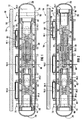
- Three pistons 34.1, 34.2 and 34.3 are axially, reciprocatingly slidingly, located inside the cylinder 26. End portions of each piston 34.1, 34.2, 34.3 are hollow, thus advantageously reducing the weight of the pistons. Furthermore, the hollow end portions of the piston 34.2 each define a bore 36 (see Figures 2 and 3) within which end portions of the pistons 34.1 and 34.3 are received in a sealing and sliding manner. The end portions of the pistons 34.1 and 34.3 are thus guided in the bores 36.
- four varying capacity chambers 38.1, 38.2, 38.3 and 38.4 for receiving and expelling hydraulic fluid are defined. These chambers can clearly be seen in Figures 1 to 5 of the drawings.
- Annular critical hydraulic fluid seals 40 seal the pistons 34.1 and 34.3 against an interior surface of the cylinder 26.
- annular hydraulic fluid seals 42 seal the pistons 34.1 and 34.3 against interior surfaces of the bores 36 defined by the piston 34.2.
- Annular bands of friction-reducing material 44 such as Vesconite (trade mark), nylon or brass act as bearing surfaces for the piston 34.2, thus facilitating axial displacement of the piston 34.2 inside the cylinder 26.
- each piston 34.1, 34.2, 34.3 defines a keyway 46 (see Figure 7 of the drawings) within which a radially horizontally extending mounting block 48 of a force transfer member 50 (see Figures 6 and 7) is secured.
- Each mounting block 48 thus extends through the slot 30 in use to transfer force from the piston 34.1, 34.2, 34.3 to which it is secured, sideways through the cylinder 26 to an associated one of the transverse drive beams 18.1, 18.2, 18.3.
- a pair of passages 52 is provided in each mounting block 48 (see Figure 6), and a pair of threaded passages 53 is provided on diagonally opposed sides of each piston 34.1, 34.2, 34.3.
- Bolts 55 are used to bolt each mounting block 48 and thus each force transfer member 50, to its associated piston 34.1, 34.2, 34.3, as shown in Figure 7 of the drawings.
- One of the mounting blocks 48 secured to the piston 34.1 and one of the mounting blocks 48 secured to the piston 34.3 each defines a hydraulic fluid passage (not shown) which is aligned with a hydraulic fluid passage 54 defined respectively by the pistons 34.1 and 34.3 and which respectively leads into the chambers 38.1 and 38.4.
- both of the mounting blocks 48 secured to the piston 34.2 define a hydraulic fluid passage 57 aligned with a hydraulic fluid passage 56 defined by the piston 34.2 and respectively leading into the chambers 38.2 and 38.3.
- a sealing arrangement such as an "O"-ring or the like, is typically used to ensure that the passages 57 connect in a leak-free manner with the passages 56.
- FIG. 8 shows some components only of a further embodiment of a linear hydraulic motor in accordance with the invention, using the same reference numerals where possible for the same parts or features as were used in relation to the motor 12.
- the piston 34.3 is shown schematically only.
- the force transfer members 50 each comprise a radially extending portion 50.1 and a vertically extending portion 50.2.
- Diagonally opposed curved external surface areas 50.3 of the piston 34.3 are corrugated (only one of the areas 50.3 is visible in Figure 8).
- Areas 50.4 of the portions 50.1 facing the areas 50.3 are complementary curved and complementary corrugated.
- the corrugations of the areas 50.3 and 50.4 thus provide an interlocking feature to inhibit relative longitudinal displacement of the piston 34.3 and the force transfer members 50.
- Bolt holes 50.5 are provided in the portions 50.1 and complementary threaded holes 50.6 are provided in the piston 34.3 to allow the portions 50.1 to be bolted to the piston 34.3.
- the portions 50.1 are extended longitudinally in one direction only, defining base portions 50.7 with corrugated upper surface areas 50.8.
- Lower surfaces 50.9 of the portions 50.2 are corrugated complementary to the surfaces 50.8 and bolt holes 50.0 extend through the portions 50.7 and into the portions 50.2, where they are threaded, allowing the portions 50.2 to be bolted from beneath to the portions 50.7.
- Upper surfaces of the portions 50.2 are then welded or bolted to an associated transverse drive beam, in this case the transverse drive beam 18.3.
- the two outer transverse drive beams 18.3 and 18.1 can be brought closer to the centre transverse drive beam 18.2, allowing the transverse beams 76 from which the linear hydraulic motor is suspended to be brought closer together. This advantageously reduces the span between the transverse beams 76, in turn reducing the deflection in the cylinder 26 when the reciprocating floor conveyor is carrying a load and advantageously providing more support to the slats 14.
- each pair of slots 30 is associated with a split collar 58 comprising an upper half 58.1 and a lower half 58.2.
- the upper and lower halves 58.1, 58.2 of the collar 58 encircle the cylinder 26.
- recesses 60 are provided to define apertures through which the mounting blocks 48 can extend.
- the collar 58 when assembled, can be slidingly displaced along the length of the cylinder 26 in the direction of the double-headed arrow 20 as shown in Figure 9 of the drawings, with the mounting blocks 48 extending through the slots 30 and limiting the longitudinal travel of the collar 58 to the length of the slots 30 minus the width of the mounting block 48, i.e. about 200 mm.
- a short sleeve or lining may be attached to the collar 58 to slide with the collar 58 over the cylinder 26.
- Each collar half 58.1, 58.2 includes a semi-circular flattened flange 62 defining two apertures 64. When assembled, the apertures 64 are aligned with threaded passages 66 in the force transfer members 50. The apertures 64 and the threaded passages 66 are thus used to bolt the force transfer members 50 to the upper and lower halves 58.1, 58.2 of the collar 58, thereby also to bolt the upper and lower halves 58.1, 58.2 together.
- Each of the transverse drive beams 18.1, 18.2, 18.3 is supported by an associated one of the upper collar halves 58.1.
- a recess is provided in a lower surface of each transverse drive beam 18.1, 18.2, 18.3, within which the upper collar half 58.1 is received.
- Two apertures 68 are provided in each force transfer member 50, through which bolts can be inserted to bolt the force transfer members 50 to their associated transverse drive beams 18.1, 18.2 and 18.3.
- the slats 14 of a group of slats 14.1, 14.2, 14.3 are secured to an associated transverse drive beam 18.1, 18.2, 18.3 by means of mounting formations 70.
- a guide block 72 is provided to support and guide each slat 14.
- Such mounting formations 70 and guide blocks 72 are known to those skilled in the art, are not described in any more detail, and the guide blocks 72 are entirely optional.
- each transverse drive beam 18.1, 18.2, 18.3 becomes thinner, in a vertical direction, away from the cylinder 26.
- each transverse drive beam 18.1, 18.2, 18.3 taper in plan view towards its free ends, away from the cylinder 26.
- the drive beams 18.1, 18.2, 18.3 thus taper in a lateral direction starting from a widest portion near or at their points of attachment to the cylinder 26, the widest portion of the drive beam 18.2 being midway between its ends and the widest portion of the drive beams 18.1, 18.3 being off-centre, so that the transverse drive beams are staggered relative to one another.
- the reciprocating floor conveyor 10 forms part of a heavy load-bearing vehicle, with the floor surface 16 defining the load-bearing surface of the vehicle.
- the reciprocating floor conveyor 10 of the invention does not necessarily have to form part of a vehicle, but can be used also in other applications.
- the linear hydraulic motor 12 is suspended between two longitudinally extending "I"-beam chassis members 74 of the vehicle.
- the linear hydraulic motor 12 is suspended from two longitudinally spaced transverse beams 76, supported on the chassis members 74.
- a semi-circular recess is provided in the bottom of each transverse beam 76.
- a half-cylindrical flanged bush 77 is welded in the recess, with the cylinder 26 of the linear hydraulic motor 12 being received inside the half-cylindrical bush 77.
- a cradle 78 is used to bolt the cylinder 26 to each of the transverse beams 76.
- each transverse beam 76 is a composite beam, comprising a central length portion 76.1 and two end portions 76.2.
- the central length portion 76.1 has a higher mass per unit length than the two end portions 76.2, being of 8 mm thick rectangular tubing, whereas the end portions 76.2 are of 2 mm thick rectangular tubing.
- a length of flat bar 80 is sandwiched between the cradle 78 and the central length portion 76.1, on each side of the cylinder 26, thereby reinforcing the central length portion 76.1.
- the flat bars 80 are welded to the central length portion 76.1 and the half-cylindrical bush 77.
- the central length portion 76.1 is supported, near its ends, by the chassis members 74.
- the end portions 76.2 are fastened to U-shaped channel members 82 forming part of the load bed of the vehicle.
- hydraulic fluid is then forced into the chamber 38.3 as shown by arrow 90 in Figure 3.
- the piston 34.3 cannot be displaced to the left.
- the piston 34.3 is then displaced to the right against the piston 34.2, in the direction of arrow 92 as shown in Figure 4 by injecting hydraulic fluid into the chamber 38.4, as shown by arrow 94 in Figure 4.
- FIG. 200 another embodiment of a linear hydraulic motor in accordance with the invention is generally indicated by reference numeral 200.
- the linear hydraulic motor 200 is similar to the linear hydraulic motor 12 and, unless otherwise indicated, the same reference numerals are used to indicate the same or similar parts or features.
- the operation of the linear hydraulic motor 200 is substantially identical to the operation of the linear hydraulic motor 12, with the only difference of importance being the manner in which the hydraulic fluid is introduced into the various chambers 38.1, 38.2, 38.3 and 38.4.
- the hydraulic fluid is injected through the conduit 202 as indicated by arrow 210 in Figures 12 and 13.
- the hydraulic fluid is injected through the conduit 204 as shown by arrow 212 in Figure 14.
- the piston 34.3 is displaced to the right by injecting the hydraulic fluid through the port 208, as shown by arrow 214 in Figure 15. All three of the pistons 34.1, 34.2 and 34.3 are then displaced to the left by injecting the hydraulic fluid through the port 206 into the chamber 38.1, as shown by arrow 216 in Figure 16.
- hydraulic fluid is removed from a chamber 38.1, 38.2, 38.3 and 38.4, when the volume of the chamber is reduced as a result of the movement of the pistons 34.1, 34.2, 34.3, by the same passage or port as with which the hydraulic fluid is injected into the chamber.
- FIG 17 shows a more detailed vertically sectioned view through an end portion of the linear hydraulic motor 200.
- a flange 210 is welded to an end of the cylinder 26.
- An end cap 212 comprising a disc-shaped end head 214 and an integral spigot portion 216 closes the open end of the cylinder 26.
- the spigot portion 216 slides into the cylinder 26 with the end head 214 abutting against the flange 210.
- Threaded bolts 218 screw into threaded bolt holes 220 to mount the end cap 212 to the cylinder 26.
- An O-ring seal 222 located in an annular groove on the spigot portion 216 ensures adequate sealing between the spigot portion 216 and the cylinder 26.
- the hydraulic fluid port 208 simply extends through the end cap 212.
- the hydraulic fluid conduit 204 comprises a passage 204.1 in the end cap 212 and a tube 204.2 bolted to the end cap 212 by means of bolts 224, with an O-ring seal 226 being provided.
- the tube 204.2 extends through the piston 34.3.
- Annular seals 228 ensure adequate sealing between the tube 204.2 and the piston 34.3.
- linear hydraulic motor 12, 200 of the invention, as illustrated, and the reciprocating floor conveyor 10, as illustrated have the following advantages compared to prior art equipment of similar load-bearing capacity of which the Applicant is aware:
Landscapes
- Engineering & Computer Science (AREA)
- Mechanical Engineering (AREA)
- Physics & Mathematics (AREA)
- Fluid Mechanics (AREA)
- General Engineering & Computer Science (AREA)
- Actuator (AREA)
- Reciprocating Conveyors (AREA)
- Types And Forms Of Lifts (AREA)
- Control Of Vehicles With Linear Motors And Vehicles That Are Magnetically Levitated (AREA)
- Hydraulic Motors (AREA)
- Fertilizing (AREA)
- Nozzles (AREA)
Abstract
Description
- THIS INVENTION relates to a linear hydraulic motor and a reciprocating floor conveyor.
-
EP 0 704 275 discloses a linear actuator which has a single piston which is reciprocatingly movable inside a cylinder, with a joint member effectively defining the piston and protruding through an upper surface of an actuator body to move a slide table reciprocatingly. FR 2 580 735 and FR 2 023 430 both disclose a linear hydraulic motor. The motor effectively has a single piston located between two chambers with force being transferred sideways from the piston through a wall of the cylinder.EP 0 259 901 discloses a reciprocating floor which has a linear hydraulic motor with fixed piston heads and cylinder housings mounted to travel on the piston heads. - According to a first aspect of the invention, broadly, there is provided a linear hydraulic motor which includes an elongate cylinder and at least one piston located slidingly inside the cylinder, characterised in that in use force is transferred from the piston transversely outwardly through the cylinder.
- The motor may thus include a force transfer component or member or means to transfer driving forces from the piston transversely outwardly through the cylinder to a driven object.
- More particularly, according to the first aspect of the invention, there is provided a linear hydraulic motor which includes
an elongate cylinder with at least one longitudinally extending aperture in a longitudinally extending wall of the cylinder;
at least two pistons slidingly located in series inside the cylinder;
at least two chambers defined inside the cylinder, with at least one of the chambers being defined between the pistons; and
a force transfer member connected to at least one of the pistons through said aperture in the cylinder wall, the pistons being movable independently from one another in at least one longitudinal direction inside the cylinder and movable in unison in a counter direction, thereby providing the motor with a stroke characterised in that, when a hydraulic fluid is forced into only one of the chambers, the pistons are simultaneously displaced in a common direction. - By "longitudinally extending aperture" is meant an aperture which extends in a direction which has at least a directional component which is longitudinal with respect to the cylinder. Preferably, the aperture has a longitudinal axis which is parallel to the longitudinal axis of the cylinder.
- Preferably, for each force transfer member, there is a longitudinally extending aperture. The apertures may be oblong and may form discrete openings in the wall of the cylinder.
- Although the Applicant expects that there may be many applications for the linear hydraulic motor of the invention, it is expected that the linear hydraulic motor will be particularly suitable for use in reciprocating floor conveyors.
- The aperture is typically spaced from ends of the cylinder. In other words, the aperture has ends that are longitudinally spaced from the ends of the cylinder. The cylinder may have end portions which are free of discontinuities that extend longitudinally between the aperture and the ends of the cylinder, advantageously allowing the cylinder to operate with a hydraulic fluid under substantial pressure without the pressure deforming the cylinder.
- Typically, the cylinder has at least two longitudinally extending, longitudinally spaced apertures and an intermediate portion between adjacent apertures, the intermediate portion being free of discontinuities extending longitudinally between the apertures. Preferably, the at least two apertures are aligned with one another, thus having centres that are spaced in a longitudinal direction, with adjacent ends of the apertures being spaced.
- The linear hydraulic motor will thus include at least two, e.g. up to four, longitudinally spaced pistons inside the cylinder. It is to be appreciated however that the number of pistons will typically be dictated by practical considerations and the application in which the linear hydraulic motor is to be used, and that there is no theoretical reason why more than four pistons cannot be included. For application in reciprocating floor conveyors, it is expected that mostly three, and sometimes two, pistons will be included.
- The cylinder typically includes an elongate body, which is preferably seamless. If desired, at least one end of the body may be domed.
- A removable cap may be located at at least one end of the elongate body. In one embodiment, the cap is screwed onto the elongate body. In another embodiment of the invention, the cap is clamped or bolted to the elongate body. In fact, the Applicant expects that in a preferred embodiment there will be two end caps, both end caps being bolted to the elongate body.
- The cap may be domed, if desired. The cap or caps may fit slidingly into the cylinder with end heads abutting against ends of the cylinder.
- An interior zone of the cylinder, with a length at least equal to the length of the aperture and into which the aperture opens, is typically unpressurised by a hydraulic fluid during any stroke of the piston. In other words, the cylinder defines a hollow interior within which the piston can slide, a portion of the hollow interior, corresponding with the location of the aperture, not being filled with a working hydraulic fluid during a stroke, in any longitudinal direction, of the piston. Advantageously, it is thus not necessary to provide for sealing around the periphery of the aperture.
- One or more of the pistons may include one or more hollow portions. Advantageously, this reduces the mass of the linear hydraulic motor. Also, in some embodiments of the invention, opposed end surfaces of at least some of the pistons are substantially equal in area to the cross-sectional internal area of the cylinder, advantageously increasing the contact area with hydraulic fluid.
- At least one of the pistons may define a bore for receiving an end portion of an adjacent piston, the bore and adjacent piston also defining between them a chamber for receiving hydraulic fluid. Thus, in use, when a hydraulic fluid is forced into the chamber defined by the bore and the adjacent piston, the piston with the bore and the adjacent piston are forced apart, with typically one of the pistons being displaced.
- The piston defining a bore may have an associated force transfer member. The end portion of the adjacent piston may describe a path in use which penetrates an interior zone of the cylinder which extends radially inwardly from the aperture in the cylinder wall for the force transfer member of the piston defining a bore. Advantageously, in this way the overall length of the cylinder can be limited and this can be achieved without providing sealing between the end portion of the adjacent piston, on the one hand, and the cylinder and the aperture on the other hand.
- Typically, the pistons and the cylinder define a plurality of chambers for receiving hydraulic fluid, the number of chambers being equal to the number of pistons plus one.
- The linear hydraulic motor may include one or more stops to prevent one of the pistons from being displaced when a hydraulic fluid is forced into a chamber between two pistons. Said stop or stops may be defined by an end cap.
- Advantageously, when the linear hydraulic motor includes a chamber defined between the bore of one piston and an end portion of an adjacent piston received inside the bore, a reduced number of critical hydraulic fluid seals are required between the pistons and the cylinder than when the chambers are not defined inside the bore of a piston. Thus, in one embodiment of the invention, the number of critical hydraulic fluid seals equals the number of pistons plus one. Further advantages of this arrangement include that the length of the cylinder and the weight of the motor are reduced.
- The linear hydraulic motor typically includes, for each piston, at least one force transfer member associated with and connected transversely outwardly through an aperture in the wall of the cylinder to the piston, to replace conventional piston rods. The force transfer member may be secured in a keyway in a side of its associated piston. Instead, or in addition, the force transfer member and its associated piston may have textured, e.g. corrugated surfaces where they contact each other.
- Preferably, each force transfer member includes a portion which projects radially away from its associated piston.
- Preferably, each piston is associated with at least a pair of force transfer members. In case of a pair of force transfer members, the force transfer members are preferably diagonally opposed to each other and each preferably includes a portion which projects radially away from its associated piston. When a piston is associated with more than two force transfer members, e.g. three, the force transfer members are preferably equiangularly spaced about the piston.
- Each force transfer member may be removably connected to its associated piston. In one embodiment of the invention, the force transfer members are each bolted to their associated pistons by means of radially extending bolts.
- At least some of the force transfer members may each define a passage for hydraulic fluid. Typically, when present, the passage is aligned with a hydraulic fluid passage defined by the associated piston and leading into one of the chambers. The hydraulic fluid passages defined by the force transfer members may be connected or connectable to a hydraulic fluid source by means of flexible conduits.
- Instead, the linear hydraulic motor may include one or more longitudinally extending passages, some of which may extend through one or more of the pistons, for hydraulic fluid. In this case, the passage or passages typically extend through one or both ends of the cylinder. Such a passage may be defined by a conduit, which may thus pass through one of the pistons. Where the conduit passes through a piston, a hydraulic fluid seal may be provided. In this case, hydraulic fluid conduits for supplying and removing hydraulic fluid to the motor may be rigid.
- The linear hydraulic motor is thus a motor which includes two or more pistons and at least two chambers defined inside the cylinder, the motor having a stroke characterised in that, when a hydraulic fluid is forced into only one chamber, all of the pistons are simultaneously displaced in a common direction. The motor also includes a chamber defined between adjacent pistons and it thus has a stroke characterised in that, when a hydraulic fluid is forced into said chamber, only one of the adjacent pistons is displaced. The other piston may be prevented from moving as a result of the presence of the stop, as hereinbefore described.
- Each longitudinally extending aperture or slot may have a longitudinally extending length of at least 100 mm, preferably between about 150 mm and about 500 mm, e.g. about 300 mm. This length is thus typically about equal to the length of a stroke of the piston associated with the aperture, plus the width of the portion of the force transfer member which projects through the aperture.
- At least a portion of an exterior surface of the wall of the cylinder may be treated in order to provide a bearing surface for supporting a sliding load on the cylinder. In one embodiment of the invention, the bearing surface may be provided by a chromed or nickel coated exterior surface portion of the wall of the cylinder. Instead, the exterior surface of the wall of the cylinder may be merely polished, with the cylinder being of a high chrome steel, i.e. a steel with more than 10.5 % chrome by weight. The steel may comply with Euronorm Standards EN 10088 or EN 10028, and may be 3CR12 steel. In another embodiment of the invention, the bearing surface is provided by a sleeve, which may be of a synthetic plastics or polymeric material such as Vesconite (trade mark) or nylon, or another suitable material with a low coefficient of kinetic friction such as brass.
- In yet another embodiment, the cylinder and/or the pistons may be of aluminium or an aluminium alloy.
- The linear hydraulic motor may include a cover or covers associated with one or more of the apertures. In one embodiment of the invention, a concertina-like sleeve is provided over the cylinder for each pair of opposed apertures. In another embodiment, a tubular sleeve over the cylinder is provided for each piston, the sleeve moving in unison with the piston.
- According to another aspect of the invention, there is provided a reciprocating floor conveyor which includes
a plurality of elongate floor members defining a floor surface and being grouped in at least two sets;
at least two transverse drive beams, each being fast with an associated set of the floor members; and
drive means drivingly connected to the transverse drive beams, the drive means including at least one linear hydraulic motor in accordance with the invention drivingly connected to at least one of the transverse drive beams.. - The drive means is thus configured to drive the elongate floor members in one direction, for advancing a load supported on the floor, and for retracting them in the opposite direction.
- Preferably, the linear hydraulic motor includes two or three longitudinally spaced pistons, each piston in use transferring force transversely outwardly through the cylinder to an associated transverse drive beam. Typically, each piston is associated with a pair of force transfer members, the force transfer members being diagonally opposed to each other. Each force transfer member may include a portion which projects radially, preferably horizontally away from the other, with the cylinder or cylinders being horizontally arranged, although portions projecting in other directions, e.g. vertically, are naturally not excluded from the scope of the invention.
- At least one of the transverse drive beams may be supported slidingly on the cylinder. In a preferred embodiment, each of the transverse drive beams is supported slidingly on the cylinder, which in the preferred embodiment is a common cylinder for all the transverse drive beams.
- At least 90 %, preferably at least 95 % of the weight of each transverse drive beam may be supported by the cylinder on which the transverse drive beam rests. In one embodiment of the invention, the entire weight of at least one of the transverse drive beams is supported by the cylinder on which it rests.
- The cylinder may have an outer diameter of at least 100 mm, preferably at least 150 mm, e.g. about 175 mm.
- Each transverse drive beam may be arranged relative to the cylinder such that the shortest radially measured distance between an outer surface of the cylinder and the floor surface is less than 120 mm, preferably less than 100 mm, e.g. about 85 mm. Advantageously, this reduces the moment about a transverse axis extending through the connection between a piston and a force transfer member, caused by inertia and/or frictional forces when a transverse drive beam is slidingly linearly displaced. A portion of the cylinder may be received inside a recess provided underneath the transverse drive beam supported by the cylinder. Instead, the transverse drive beam may be elevated entirely above the upper outer surface of the cylinder.
- At least one of the transverse drive beams may support at least some of the elongate floor members not forming part of the associated set of elongate floor members fast with said at least one transverse drive beam. Said at least one transverse drive beam may thus include guide formations guiding and supporting the elongate floor members not fast with said at least one transverse drive beam.
- At least one of the transverse drive beams may taper outwardly towards free ends thereof, thus having an operative vertical dimension decreasing from immediately adjacent the cylinder supporting it towards its free ends. Similarly, in plan view, at least one of the transverse drive beams may taper outwardly from its middle towards its opposed free ends.
- The cylinder of the at least one linear hydraulic motor may be fastened to two or more transverse beams forming part of or fast with a chassis of a vehicle or other structure. A portion of the cylinder may be received in a recess provided in the bottom of each transverse beam.
- At least one cradle associated with and fastened to one of the transverse beams may support the cylinder.
- At least one of the transverse beams may be a composite beam, comprising a central length portion of higher mass per unit length, and two end portions of lower mass per unit length, end regions of the central length portion being supported by longitudinally extending members of the chassis.
- The linear hydraulic motor thus has a working stroke in which a hydraulic fluid forced into a chamber inside the cylinder displaces all of the pistons simultaneously in a common direction.
- According to a further aspect of the invention, there is provided a reciprocating floor conveyor linear hydraulic motor assembly, the assembly including a linear hydraulic motor in accordance with the invention spanning between two transverse beams and being fast with the beams at locations longitudinally spaced along the length of the cylinder of the motor, the beams being connected to each other and braced to resist relative movement by means of the cylinder only.
- The assembly may thus be a modular unit ready for installation to form part of a reciprocating floor conveyor.
- The assembly may be configured to form part of a reciprocating floor conveyor in accordance with the invention. The transverse beams may thus be fastened to the cylinder at locations not occupied by transverse drive beams of the motor during travel of the transverse drive beams in use, immediately adjacent longitudinally spaced end borders of a space occupied by outermost transverse drive beams during their travel.
- The invention will now be described, by way of example only, with reference to the accompanying diagrammatic drawings in which
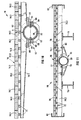
- Figures 1 to 5 show a vertical, longitudinal section through a portion of a reciprocating floor conveyor in accordance with the invention, and which includes a linear hydraulic motor in accordance with the invention;
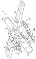
- Figure 6 shows an exploded three-dimensional view of some components only of the linear hydraulic motor of Figure 1, and one transverse drive beam of the reciprocating floor conveyor of Figure 1;
- Figure 7 shows a longitudinal horizontal section taken at VII-VII in Figure 6 of the drawings;
- Figure 8 shows an exploded three-dimensional view of some components only of a further embodiment of a linear hydraulic motor in accordance with the invention;
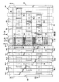
- Figure 9 shows a plan view of a portion of the reciprocating floor conveyor of Figure 1;
- Figure 10 shows a vertical transverse section taken at IX-IX in Figure 8;
- Figure 11 shows a vertical transverse section taken at X-X in Figure 8;
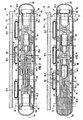
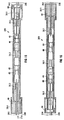
- Figures 12 to 16 show a vertical longitudinal section through another embodiment of a linear hydraulic motor in accordance with the invention, with some detail omitted for clarity and the drawings being of a schematic nature only; and
- Figure 17 shows an exploded vertical longitudinal section through an end portion of the linear hydraulic motor of Figures 12 to 16, in more detail.
- Referring to Figures 1 to 11 of the drawings,
reference numeral 10 generally indicates a reciprocating floor conveyor in accordance with the invention, which includes a linear hydraulic motor in accordance with the invention, generally designated byreference numeral 12. - The
reciprocating floor conveyor 10 comprises a plurality of elongate floor members orslats 14 arranged side-by-side to define a floor surface 16 (see Figure 9). Theslats 14 are grouped together in three groups 14.1, 14.2 and 14.3. Thus, when starting from the left, thefirst slat 14, and every third slat thereafter, belongs to the group 14.1. The second slat, and every third slat thereafter belongs to the group 14.2 and the third slat, and every third slat thereafter, belongs to the group 14.3. - The slats of the group 14.1 are attached to a transverse drive beam 18.1, the slats of the group 14.2 are attached to a transverse drive beam 18.2 and the slats of the group 14.3 are attached to a transverse drive beam 18.3.
- By means of the linear
hydraulic motor 12, the transverse drive beams 18.1, 18.2, 18.3, and thus the groups of slats 14.1, 14.2, 14.3 are reciprocatingly moved backwards and forwards in a particular sequence, in the direction of the double-headedarrow 20 shown in Figure 9. The operation of a reciprocating floor conveyor is well known to those skilled in the art, and only a very brief description of the sequence of the displacement of the groups of slats 14.1, 14.2, 14.3 will be given. - In order to displace a load, such as a load of wood chips supported on the
floor surface 16, the group of slats 14.1 are displaced longitudinally by means of the transverse drive beam 18.1 in say the direction ofarrow 22 shown in Figure 9. Thereafter, the group of slats 14.2 are displaced by means of the transverse drive beam 18.2 in the direction of thearrow 22, followed by the displacement of the group of slats 14.3 by means of the transverse drive beam 18.3, in the direction ofarrow 22. As will be appreciated, with one third of theslats 14 only being displaced each time, the load supported on thefloor surface 16 remains stationary. Once all three groups 14.1, 14.2, 14.3 have been displaced in the direction of thearrow 22, all three groups 14.1, 14.2, 14.3 are simultaneously displaced in the direction ofarrow 24, thus moving the entire load supported on thefloor surface 16 in the direction of thearrow 24. This process is then repeated in order to move the load stepwise over thesurface 16. - The linear
hydraulic motor 12 will now be described in more detail. Themotor 12 comprises an elongate circularcylindrical cylinder 26. In the embodiment shown in Figures 1-6, ends of thecylinder 26 are closed by means ofdomed end caps 28. Typically, at least one of the end caps 28 is removable, and may thus be screwed or bolted to thecylinder 26. No particular fastening mechanism is shown in the drawings. - Six longitudinally extending apertures or
slots 30 are provided in thecylinder 26. Theslots 30 are arranged in three groups of two each, with the twoslots 30 of each group being located on diagonally opposed sides of thecylinder 26, facing sideways in a horizontal direction. In the embodiment of the linearhydraulic motor 12 shown in the drawings, thecylinder 26 has an internal diameter of about 145 mm, a length of about 1600 mm, andslots 30 with a length of about 300 mm each. - A
sleeve 32 of a friction-reducing material, such as Vesconite (trade mark), nylon or brass, is fitted over thecylinder 26. Theslots 30 extend also through thesleeve 32. - Three pistons 34.1, 34.2 and 34.3 are axially, reciprocatingly slidingly, located inside the
cylinder 26. End portions of each piston 34.1, 34.2, 34.3 are hollow, thus advantageously reducing the weight of the pistons. Furthermore, the hollow end portions of the piston 34.2 each define a bore 36 (see Figures 2 and 3) within which end portions of the pistons 34.1 and 34.3 are received in a sealing and sliding manner. The end portions of the pistons 34.1 and 34.3 are thus guided in thebores 36. Thus, between thecylinder 26 and the pistons 34.1, 34.2 and 34.3, four varying capacity chambers 38.1, 38.2, 38.3 and 38.4 for receiving and expelling hydraulic fluid are defined. These chambers can clearly be seen in Figures 1 to 5 of the drawings. - Annular critical hydraulic fluid seals 40 seal the pistons 34.1 and 34.3 against an interior surface of the
cylinder 26. Similarly, annular hydraulic fluid seals 42 seal the pistons 34.1 and 34.3 against interior surfaces of thebores 36 defined by the piston 34.2. Annular bands of friction-reducingmaterial 44, such as Vesconite (trade mark), nylon or brass act as bearing surfaces for the piston 34.2, thus facilitating axial displacement of the piston 34.2 inside thecylinder 26. - Associated with each
slot 30, each piston 34.1, 34.2, 34.3 defines a keyway 46 (see Figure 7 of the drawings) within which a radially horizontally extending mountingblock 48 of a force transfer member 50 (see Figures 6 and 7) is secured. Each mountingblock 48 thus extends through theslot 30 in use to transfer force from the piston 34.1, 34.2, 34.3 to which it is secured, sideways through thecylinder 26 to an associated one of the transverse drive beams 18.1, 18.2, 18.3. - A pair of
passages 52 is provided in each mounting block 48 (see Figure 6), and a pair of threadedpassages 53 is provided on diagonally opposed sides of each piston 34.1, 34.2, 34.3. Bolts 55 (see Figure 7) are used to bolt each mountingblock 48 and thus eachforce transfer member 50, to its associated piston 34.1, 34.2, 34.3, as shown in Figure 7 of the drawings. - One of the mounting
blocks 48 secured to the piston 34.1 and one of the mountingblocks 48 secured to the piston 34.3 each defines a hydraulic fluid passage (not shown) which is aligned with ahydraulic fluid passage 54 defined respectively by the pistons 34.1 and 34.3 and which respectively leads into the chambers 38.1 and 38.4. Similarly, both of the mountingblocks 48 secured to the piston 34.2 define ahydraulic fluid passage 57 aligned with ahydraulic fluid passage 56 defined by the piston 34.2 and respectively leading into the chambers 38.2 and 38.3. Although not shown in the drawings, a sealing arrangement, such as an "O"-ring or the like, is typically used to ensure that thepassages 57 connect in a leak-free manner with thepassages 56. - An alternative configuration for the
force transfer members 50 is shown in Figure 8 of the drawings. Figure 8 shows some components only of a further embodiment of a linear hydraulic motor in accordance with the invention, using the same reference numerals where possible for the same parts or features as were used in relation to themotor 12. The piston 34.3 is shown schematically only. Theforce transfer members 50 each comprise a radially extending portion 50.1 and a vertically extending portion 50.2. Diagonally opposed curved external surface areas 50.3 of the piston 34.3 are corrugated (only one of the areas 50.3 is visible in Figure 8). Areas 50.4 of the portions 50.1 facing the areas 50.3 are complementary curved and complementary corrugated. The corrugations of the areas 50.3 and 50.4 thus provide an interlocking feature to inhibit relative longitudinal displacement of the piston 34.3 and theforce transfer members 50. Bolt holes 50.5 are provided in the portions 50.1 and complementary threaded holes 50.6 are provided in the piston 34.3 to allow the portions 50.1 to be bolted to the piston 34.3. - The portions 50.1 are extended longitudinally in one direction only, defining base portions 50.7 with corrugated upper surface areas 50.8. Lower surfaces 50.9 of the portions 50.2 are corrugated complementary to the surfaces 50.8 and bolt holes 50.0 extend through the portions 50.7 and into the portions 50.2, where they are threaded, allowing the portions 50.2 to be bolted from beneath to the portions 50.7. Upper surfaces of the portions 50.2 are then welded or bolted to an associated transverse drive beam, in this case the transverse drive beam 18.3.
- With the configuration shown in Figure 8 of the drawings, the two outer transverse drive beams 18.3 and 18.1 can be brought closer to the centre transverse drive beam 18.2, allowing the
transverse beams 76 from which the linear hydraulic motor is suspended to be brought closer together. This advantageously reduces the span between thetransverse beams 76, in turn reducing the deflection in thecylinder 26 when the reciprocating floor conveyor is carrying a load and advantageously providing more support to theslats 14. - Referring now again to the
reciprocating floor conveyor 10 with theforce transfer members 50 of the configuration shown in Figure 6 (in which many components have been omitted for clarity and in which only one pair ofslots 30 is shown), each pair ofslots 30 is associated with asplit collar 58 comprising an upper half 58.1 and a lower half 58.2. The upper and lower halves 58.1, 58.2 of thecollar 58 encircle thecylinder 26. Along longitudinally extending edges of the halves 58.1, 58.2 where they meet, recesses 60 are provided to define apertures through which the mounting blocks 48 can extend. Thus, when assembled, thecollar 58 can be slidingly displaced along the length of thecylinder 26 in the direction of the double-headedarrow 20 as shown in Figure 9 of the drawings, with the mountingblocks 48 extending through theslots 30 and limiting the longitudinal travel of thecollar 58 to the length of theslots 30 minus the width of the mountingblock 48, i.e. about 200 mm. Instead of thesleeve 32 fitted over thecylinder 26, a short sleeve or lining may be attached to thecollar 58 to slide with thecollar 58 over thecylinder 26. - Each collar half 58.1, 58.2 includes a semi-circular flattened
flange 62 defining twoapertures 64. When assembled, theapertures 64 are aligned with threadedpassages 66 in theforce transfer members 50. Theapertures 64 and the threadedpassages 66 are thus used to bolt theforce transfer members 50 to the upper and lower halves 58.1, 58.2 of thecollar 58, thereby also to bolt the upper and lower halves 58.1, 58.2 together. - Each of the transverse drive beams 18.1, 18.2, 18.3 is supported by an associated one of the upper collar halves 58.1. As can be clearly seen in Figure 6 of the drawings, in the embodiment shown, a recess is provided in a lower surface of each transverse drive beam 18.1, 18.2, 18.3, within which the upper collar half 58.1 is received. Two
apertures 68 are provided in eachforce transfer member 50, through which bolts can be inserted to bolt theforce transfer members 50 to their associated transverse drive beams 18.1, 18.2 and 18.3. Thus, as will be appreciated, when a piston, such as the piston 13.2, is displaced axially inside thecylinder 26, its associated transverse drive beam 18.2 moves in unison with the piston 34.2. - The
slats 14 of a group of slats 14.1, 14.2, 14.3 are secured to an associated transverse drive beam 18.1, 18.2, 18.3 by means of mountingformations 70. Where theslats 14 of one of the groups pass over the transverse drive beam to which theslats 14 of another group are secured, aguide block 72 is provided to support and guide eachslat 14. Such mountingformations 70 and guide blocks 72 are known to those skilled in the art, are not described in any more detail, and the guide blocks 72 are entirely optional. - As can be clearly seen in Figure 6 of the drawings, each transverse drive beam 18.1, 18.2, 18.3 becomes thinner, in a vertical direction, away from the
cylinder 26. Similarly, as shown in Figure 9 of the drawings, each transverse drive beam 18.1, 18.2, 18.3 taper in plan view towards its free ends, away from thecylinder 26. The drive beams 18.1, 18.2, 18.3 thus taper in a lateral direction starting from a widest portion near or at their points of attachment to thecylinder 26, the widest portion of the drive beam 18.2 being midway between its ends and the widest portion of the drive beams 18.1, 18.3 being off-centre, so that the transverse drive beams are staggered relative to one another. - The
reciprocating floor conveyor 10, as illustrated, forms part of a heavy load-bearing vehicle, with thefloor surface 16 defining the load-bearing surface of the vehicle. However, as will be appreciated, thereciprocating floor conveyor 10 of the invention does not necessarily have to form part of a vehicle, but can be used also in other applications. - As shown in Figure 11, the linear
hydraulic motor 12 is suspended between two longitudinally extending "I"-beam chassis members 74 of the vehicle. The linearhydraulic motor 12 is suspended from two longitudinally spacedtransverse beams 76, supported on thechassis members 74. As also shown in Figure 11 of the drawings, a semi-circular recess is provided in the bottom of eachtransverse beam 76. A half-cylindricalflanged bush 77 is welded in the recess, with thecylinder 26 of the linearhydraulic motor 12 being received inside the half-cylindrical bush 77. Acradle 78 is used to bolt thecylinder 26 to each of the transverse beams 76. - In the embodiment shown in the drawings, each
transverse beam 76 is a composite beam, comprising a central length portion 76.1 and two end portions 76.2. The central length portion 76.1 has a higher mass per unit length than the two end portions 76.2, being of 8 mm thick rectangular tubing, whereas the end portions 76.2 are of 2 mm thick rectangular tubing. A length offlat bar 80 is sandwiched between thecradle 78 and the central length portion 76.1, on each side of thecylinder 26, thereby reinforcing the central length portion 76.1. The flat bars 80 are welded to the central length portion 76.1 and the half-cylindrical bush 77. - As can be clearly seen in Figure 11, the central length portion 76.1 is supported, near its ends, by the
chassis members 74. The end portions 76.2 are fastened toU-shaped channel members 82 forming part of the load bed of the vehicle. - Between the
adjacent collars 58, and between thecollars 58 and thetransverse beams 76, concertina-like rubber sleeves 84 are located, to ensure that theslots 30 are always protected against ingress of dirt or the like. - With reference to Figures 1 to 5, the operation of the linear
hydraulic motor 10 is now described. In Figure 1, all three of the pistons 34.1, 34.2, 34.3 are shown in positions where they are as far to the left inside thecylinder 26 as possible. In order to displace the transverse drive beam 18.1 in the direction of arrow 84 (see Figure 1), and thus also to displace theslats 14 of the group of slats 14.1 in the direction of thearrow 84, a hydraulic fluid, typically a hydraulic oil, is injected into the chamber 38.2, as shown byarrow 86 in Figures 1 and 2, thus forcing the piston 34.1 to the right as far as it can go, as shown in Figure 2. At this time, the pistons 34.2 and 34.3 cannot be displaced to the left. In order to displace the piston 34.2 to the right as shown byarrow 88 in Figure 3, hydraulic fluid is then forced into the chamber 38.3 as shown byarrow 90 in Figure 3. At this time, the piston 34.3 cannot be displaced to the left. The piston 34.3 is then displaced to the right against the piston 34.2, in the direction ofarrow 92 as shown in Figure 4 by injecting hydraulic fluid into the chamber 38.4, as shown byarrow 94 in Figure 4. In order to return all three of the pistons 34.1, 34.2, 34.3 to the starting position in which they are as far to the left as possible, as shown byarrows 96 in Figure 5, hydraulic fluid is forced into the chamber 38.1 as shown by thearrow 98 in Figure 5, thus pushing all three pistons 34.1, 34.2, 34.3 simultaneously to the left. In this fashion, the movement sequence of the groups of slats 14.1, 14.2, 14.3 is established. It is however to be appreciated that the sequence can also be reversed, with all the pistons starting at the right in Figure 1. - Referring to Figures 12 to 16 of the drawings, another embodiment of a linear hydraulic motor in accordance with the invention is generally indicated by
reference numeral 200. The linearhydraulic motor 200 is similar to the linearhydraulic motor 12 and, unless otherwise indicated, the same reference numerals are used to indicate the same or similar parts or features. - One of the differences between the linear
hydraulic motor 12 and the linearhydraulic motor 200 is that the pistons 34.1 and 34.2, and 34.2 and 34.3, abut against each other, with no portion of the outer pistons 34.1, 34.3 being received inside the central piston 34.2. As a result, additional hydraulic fluid seals 40 are required. - A further difference between the linear
hydraulic motor 200 and the linearhydraulic motor 12, is that, in the linearhydraulic motor 200, the mountingblocks 48 and the pistons 34.1, 34.2, 34.3 do not define hydraulic fluid passages. Instead, a hydraulicfluid conduit 202 extends through an end of thecylinder 26, through the piston 34.1, into the chamber 38.2. Similarly, a hydraulicfluid conduit 204 extends through an opposite end of thecylinder 26, through the piston 34.3, into the chamber 38.3. For the chambers 38.1 and 38.4,hydraulic fluid ports - Despite the differences between the linear
hydraulic motor 10 and the linearhydraulic motor 200, the operation of the linearhydraulic motor 200 is substantially identical to the operation of the linearhydraulic motor 12, with the only difference of importance being the manner in which the hydraulic fluid is introduced into the various chambers 38.1, 38.2, 38.3 and 38.4. Thus, in order to displace the piston 34.1 to the right, the hydraulic fluid is injected through theconduit 202 as indicated byarrow 210 in Figures 12 and 13. In order to displace the piston 34.2 to the right, the hydraulic fluid is injected through theconduit 204 as shown byarrow 212 in Figure 14. The piston 34.3 is displaced to the right by injecting the hydraulic fluid through theport 208, as shown byarrow 214 in Figure 15. All three of the pistons 34.1, 34.2 and 34.3 are then displaced to the left by injecting the hydraulic fluid through theport 206 into the chamber 38.1, as shown byarrow 216 in Figure 16. - As will be appreciated, hydraulic fluid is removed from a chamber 38.1, 38.2, 38.3 and 38.4, when the volume of the chamber is reduced as a result of the movement of the pistons 34.1, 34.2, 34.3, by the same passage or port as with which the hydraulic fluid is injected into the chamber.
- Figure 17 shows a more detailed vertically sectioned view through an end portion of the linear
hydraulic motor 200. As can be seen in Figure 17, aflange 210 is welded to an end of thecylinder 26. Anend cap 212 comprising a disc-shapedend head 214 and anintegral spigot portion 216 closes the open end of thecylinder 26. Thespigot portion 216 slides into thecylinder 26 with theend head 214 abutting against theflange 210. Threadedbolts 218 screw into threaded bolt holes 220 to mount theend cap 212 to thecylinder 26. An O-ring seal 222 located in an annular groove on thespigot portion 216 ensures adequate sealing between thespigot portion 216 and thecylinder 26. - As can be seen in Figure 17, the hydraulic
fluid port 208 simply extends through theend cap 212. The hydraulicfluid conduit 204 comprises a passage 204.1 in theend cap 212 and a tube 204.2 bolted to theend cap 212 by means ofbolts 224, with an O-ring seal 226 being provided. The tube 204.2 extends through the piston 34.3.Annular seals 228 ensure adequate sealing between the tube 204.2 and the piston 34.3. - The other end portion of the linear
hydraulic motor 200 of Figures 12 to 16 is identical to the end portion shown in Figure 17. - As will be appreciated, various combinations of the features illustrated in Figures 1 to 7, Figure 8, Figures 12 to 16 and Figure 17 can be used together in an embodiment of the linear hydraulic motor and the reciprocating floor conveyor of the invention. The Applicant however expects that a preferred embodiment of the linear hydraulic motor and the reciprocating floor conveyor of the invention will include the pistons and cylinder more-or-less as shown in Figures 1 to 5 with the force transfer members as shown in Figure 8 and the end caps, hydraulic fluid ports and hydraulic fluid conduits illustrated in Figure 17 of the drawings.
- The linear
hydraulic motor reciprocating floor conveyor 10, as illustrated, have the following advantages compared to prior art equipment of similar load-bearing capacity of which the Applicant is aware: - The equipment is of lower mass and it is expected that the equipment can be produced at lower cost. In some embodiments of the linear hydraulic motor, the linear hydraulic motor requires fewer critical hydraulic fluid seals. The cylinder is closed and any hydraulic fluid leaking past the critical hydraulic seals on the middle piston is contained in a central zone of the cylinder, ensuring that the motor is environmentally friendly. If desired or necessary, the leaked hydraulic fluid can be periodically tapped from said central zone in a controlled manner. The cylinder acts as a support and guide for the transverse drive beams, thus protecting the pistons and seals against stresses induced by the transverse drive beams. The cylinder can be of a substantial diameter, increasing the linear force that can be produced by means of the linear hydraulic motor. Also as a result of the large cylinder diameter, the cylinder can support the entire weight of the transverse drive beams and some of the weight of the slats, making it unnecessary to provide further support beams on which the transverse drive beams are slidingly supported, whilst at the same time protecting the pistons against scuffing. Due to the lack of the presence of a rod, minimal tensile forces are introduced to the pistons. The hollow pistons reduce the overall weight of the linear hydraulic motor. The linear hydraulic motor is shorter and narrower than prior art motors of which the Applicant is aware.
- The compactness of the linear hydraulic motor allows for the radially measured distance R (see Figure 10) between a surface of the cylinder and the floor surface to be small. Each transverse drive beam may also support and guide slats not fast with said transverse drive beam. Due to the configuration of the hydraulic motor, only one chamber has to be pressurised with hydraulic liquid in order for a labour or working stroke to be effected in which all of the pistons are simultaneously displaced in the same direction.
Claims (17)
- A linear hydraulic motor (12) which includes
an elongate cylinder (26) with at least one longitudinally extending aperture (30) in a longitudinally extending wall of the cylinder (26);
at least two pistons (34) slidingly located in series inside the cylinder (26);
at least two chambers (38) defined inside the cylinder (26), with at least one of the chambers (38) being defined between the pistons (34); and
a force transfer member (50) connected to at least one of the pistons (34) through said aperture (30) in the cylinder wall, the pistons (34) being movable independently from one another in at least one longitudinal direction inside the cylinder (26) and movable in unison in a counter direction, thereby providing the motor (12) with a stroke characterised in that, when a hydraulic fluid is forced into only one of the chambers (38), the pistons (34) are simultaneously displaced in a common direction. - A linear hydraulic motor (12) as claimed in claim 1, in which the aperture (30) is spaced from ends of the cylinder (26), the cylinder (26) having end portions which are free of discontinuities that extend longitudinally between the aperture (30) and the ends of the cylinder (26).
- A linear hydraulic motor (12) as claimed in claim 1 or claim 2, in which the cylinder (26) has at least two longitudinally extending, longitudinally spaced apertures (30) and an intermediate portion between adjacent apertures (30), the intermediate portion being free of discontinuities extending longitudinally between the apertures (30).
- A linear hydraulic motor (12) as claimed in any one of claims 1 to 3 inclusive, in which the cylinder (26) includes an elongate body, a removable cap (28) being located at at least one end of the elongate body and the cylinder (26) being of a corrosion resistant steel having a chrome content of at least 10.5 % by weight.
- A linear hydraulic motor (12) as claimed in any one of claims 1 to 4 inclusive, in which an interior zone of the cylinder (26), with a length at least equal to the length of the aperture (30) and into which the aperture (30) opens, is unpressurised by a hydraulic fluid during any stroke of the piston (34).
- A linear hydraulic motor (12) as claimed in any one of claims 1 to 5 inclusive, in which one or more of the pistons (34) includes one or more hollow portions.
- A linear hydraulic motor (12) as claimed in any one of claims 1 to 6 inclusive, in which at least one of the pistons (34) defines a bore (36) for receiving an end portion of an adjacent piston (34), the bore (36) and adjacent piston (34) defining between them a chamber (38) for receiving hydraulic fluid.
- A linear hydraulic motor (12) as claimed in claim 7, in which the piston (34) defining a bore (36) has an associated force transfer member (50), and in which the end portion of the adjacent piston (34) describes a path in use which penetrates an interior zone of the cylinder(26) which extends radially inwardly from the aperture (30) in the cylinder wall for the force transfer member (50) of the piston (34) defining a bore (36).
- A linear hydraulic motor (12) as claimed in any one of claims 1 to 8 inclusive, which includes, for each piston (34), at least one force transfer member (50) associated with and connected transversely outwardly through an aperture (30) in the wall of the cylinder (26) to the piston (34).
- A linear hydraulic motor (12) as claimed in claim 9, in which each piston (34) is associated with at least a pair of force transfer members (50), the force transfer members (50) being diagonally opposed to each other and each including a portion which projects radially away from its associated piston (34).
- A linear hydraulic motor (12) as claimed in any one of claims 1 to 10 inclusive, which includes at least one longitudinally extending hydraulic fluid passage (202) which extends through one or more of the pistons.
- A reciprocating floor conveyor (10) which includes
a plurality of elongate floor members (14) defining a floor surface (16) and being grouped in at least two sets (14.1,14.2,14.3);
at least two transverse drive beams (18), each being fast with an associated set (14.1,14.2,14.3) of the floor members (14); and
drive means drivingly connected to the transverse drive beams, the drive means including at least one linear hydraulic motor (10) as claimed in any one of the preceding claims drivingly connected to at least one of the transverse drive beams (18) - A reciprocating floor conveyor (10) as claimed in claim 12, in which at least one of the transverse drive beams (18) is supported slidingly on the cylinder (26)
- A reciprocating floor conveyor (10) as claimed in claim 13, in which the cylinder (26) is of sufficiently large diameter to allow at least 90 % of the weight of each transverse drive beam (18) to be supported by the cylinder (26) on which the transverse drive beam (18) rests.
- A reciprocating floor conveyor (10) as claimed in any one of claims 12 to 14 inclusive, in which at least one of the transverse drive beams (18) supports at least some of the elongate floor members (14) not forming part of the associated set (14.1,14.2,14.3) of elongate floor members (14) fast with said at least one transverse drive beam (18).
- A reciprocating floor conveyor (10) as claimed in any one of claims 12 to 15 inclusive, in which each transverse drive beam (18) is arranged relative to the cylinder (26) such that the shortest radially measured distance between an outer surface of the cylinder (26) and the floor surface (16) is less than 120 mm.
- A reciprocating floor conveyor linear hydraulic motor assembly, which includes a linear hydraulic motor (12) as claimed in any one of claims 1 to 12 inclusive, the motor (12) spanning between two transverse beams (76) and being fast with the beams (76) at locations longitudinally spaced along the length of the cylinder (26) of the motor (12), the beams (76) being connected to each other and braced to resist relative movement by means of the cylinder (26) only.
Priority Applications (1)
| Application Number | Priority Date | Filing Date | Title |
|---|---|---|---|
| EP07006171A EP1801043A3 (en) | 2003-01-30 | 2004-01-30 | A reciprocating floor conveyor |
Applications Claiming Priority (3)
| Application Number | Priority Date | Filing Date | Title |
|---|---|---|---|
| ZA200300838 | 2003-01-30 | ||
| ZA200300838 | 2003-01-30 | ||
| PCT/IB2004/000219 WO2004067967A1 (en) | 2003-01-30 | 2004-01-30 | A linear hydraulic motor and a reciprocating floor conveyor |
Related Child Applications (1)
| Application Number | Title | Priority Date | Filing Date |
|---|---|---|---|
| EP07006171A Division EP1801043A3 (en) | 2003-01-30 | 2004-01-30 | A reciprocating floor conveyor |
Publications (2)
| Publication Number | Publication Date |
|---|---|
| EP1592890A1 EP1592890A1 (en) | 2005-11-09 |
| EP1592890B1 true EP1592890B1 (en) | 2007-03-28 |
Family
ID=32825830
Family Applications (2)
| Application Number | Title | Priority Date | Filing Date |
|---|---|---|---|
| EP04706750A Expired - Lifetime EP1592890B1 (en) | 2003-01-30 | 2004-01-30 | A linear hydraulic motor and a reciprocating floor conveyor |
| EP07006171A Withdrawn EP1801043A3 (en) | 2003-01-30 | 2004-01-30 | A reciprocating floor conveyor |
Family Applications After (1)
| Application Number | Title | Priority Date | Filing Date |
|---|---|---|---|
| EP07006171A Withdrawn EP1801043A3 (en) | 2003-01-30 | 2004-01-30 | A reciprocating floor conveyor |
Country Status (9)
| Country | Link |
|---|---|
| US (1) | US7584838B2 (en) |
| EP (2) | EP1592890B1 (en) |
| AT (1) | ATE358238T1 (en) |
| CA (1) | CA2515358A1 (en) |
| DE (1) | DE602004005573T2 (en) |
| ES (1) | ES2286601T3 (en) |
| MX (1) | MXPA05008162A (en) |
| WO (1) | WO2004067967A1 (en) |
| ZA (1) | ZA200506379B (en) |
Families Citing this family (8)
| Publication number | Priority date | Publication date | Assignee | Title |
|---|---|---|---|---|
| US7661523B2 (en) * | 2004-11-02 | 2010-02-16 | Rene Wegkamp | Linear hydraulic motor and reciprocating floor conveyor |
| EP2415694A1 (en) | 2005-11-10 | 2012-02-08 | Rene Wegkamp | A mounting arrangement |
| US20090107807A1 (en) * | 2005-11-10 | 2009-04-30 | Rene Wegkamp | Reciprocating Floor |
| FR2905427B1 (en) * | 2006-09-06 | 2008-11-21 | Hydro Leduc Soc Par Actions Si | PERFECTED LINEAR MOTOR. |
| GB2491629B (en) * | 2011-06-10 | 2013-05-22 | Oliver Dixon | An apparatus for removing material from a reciprocating floor container |
| US9057181B2 (en) * | 2012-11-09 | 2015-06-16 | Fluid Dynamics Holdings, LLC | Water flow valve for improving accuracy of meter readings in communication with a water distribution system |
| US11313109B2 (en) | 2018-04-05 | 2022-04-26 | Microflow, Llc, A Delaware Limited Liability Company | Valve for controlling water flow and for improving water meter health and readings |
| US10611579B2 (en) * | 2018-07-05 | 2020-04-07 | Keith Manufacturing Co. | End plug for floor slat |
Family Cites Families (14)
| Publication number | Priority date | Publication date | Assignee | Title |
|---|---|---|---|---|
| SE326376B (en) * | 1968-11-15 | 1970-07-20 | Mecmatic Ab | |
| DE3514074A1 (en) * | 1985-04-18 | 1986-10-23 | Herion-Werke Kg, 7012 Fellbach | Rodless cylinder |
| US4821868A (en) * | 1986-09-08 | 1989-04-18 | Foster Raymond K | Drive/frame assembly for a reciprocating floor |
| US4748893A (en) * | 1986-09-08 | 1988-06-07 | Foster Raymond K | Drive/frame assembly for a reciprocating floor |
| US4899870A (en) * | 1987-07-01 | 1990-02-13 | Foster Raymond K | Reciprocating floor conveyor with snap-on floor members |
| US4817783A (en) * | 1988-05-03 | 1989-04-04 | Foster Raymond K | Single piston rod hydraulic drive |
| US5605221A (en) * | 1994-09-12 | 1997-02-25 | Foster; Raymond K. | Drive unit with bearing mount |
| JP3655367B2 (en) * | 1994-09-30 | 2005-06-02 | Smc株式会社 | Linear actuator |
| US5433312A (en) * | 1994-10-21 | 1995-07-18 | Foster; Raymond K. | Drive assembly for conveyor slats of reciprocating floor conveyor |
| US6003660A (en) * | 1999-03-24 | 1999-12-21 | Foster; Raymond Keith | Drive units and drive assembly for a reciprocating slat conveyors |
| US6056113A (en) * | 1999-10-13 | 2000-05-02 | Foster; Raymond Keith | Drive beam to drive unit connections |
| ES2223988T3 (en) * | 2002-04-05 | 2005-03-01 | FESTO AG & CO | LIQUID DRIVEN DRIVE DEVICE. |
| US6994012B2 (en) * | 2003-02-26 | 2006-02-07 | Keith Investments, Llc | Drive units and drive assemblies |
| US7320395B2 (en) * | 2005-03-02 | 2008-01-22 | Cargo Floor B.V. | Floor for cargo space |
-
2004
- 2004-01-30 EP EP04706750A patent/EP1592890B1/en not_active Expired - Lifetime
- 2004-01-30 EP EP07006171A patent/EP1801043A3/en not_active Withdrawn
- 2004-01-30 WO PCT/IB2004/000219 patent/WO2004067967A1/en not_active Ceased
- 2004-01-30 CA CA002515358A patent/CA2515358A1/en not_active Abandoned
- 2004-01-30 US US10/543,854 patent/US7584838B2/en not_active Expired - Fee Related
- 2004-01-30 MX MXPA05008162A patent/MXPA05008162A/en active IP Right Grant
- 2004-01-30 ES ES04706750T patent/ES2286601T3/en not_active Expired - Lifetime
- 2004-01-30 DE DE602004005573T patent/DE602004005573T2/en not_active Expired - Lifetime
- 2004-01-30 AT AT04706750T patent/ATE358238T1/en not_active IP Right Cessation
-
2005
- 2005-08-10 ZA ZA200506379A patent/ZA200506379B/en unknown
Also Published As
| Publication number | Publication date |
|---|---|
| DE602004005573D1 (en) | 2007-05-10 |
| ZA200506379B (en) | 2007-02-28 |
| WO2004067967A1 (en) | 2004-08-12 |
| EP1801043A3 (en) | 2012-04-04 |
| ATE358238T1 (en) | 2007-04-15 |
| US20060260463A1 (en) | 2006-11-23 |
| US7584838B2 (en) | 2009-09-08 |
| MXPA05008162A (en) | 2006-02-17 |
| EP1801043A2 (en) | 2007-06-27 |
| ES2286601T3 (en) | 2007-12-01 |
| EP1592890A1 (en) | 2005-11-09 |
| CA2515358A1 (en) | 2004-08-12 |
| DE602004005573T2 (en) | 2007-12-13 |
Similar Documents
| Publication | Publication Date | Title |
|---|---|---|
| CA1315646C (en) | Drive/frame assembly for a reciprocating floor | |
| US4748893A (en) | Drive/frame assembly for a reciprocating floor | |
| US7584838B2 (en) | Linear hydraulic motor and a reciprocating floor conveyor | |
| US20090289496A1 (en) | Chain tensioning device | |
| EP1428776B1 (en) | Drive assembly for reciprocating slat conveyor | |
| EP1815147B1 (en) | Linear hydraulic motor and reciprocating floor conveyor | |
| US6056113A (en) | Drive beam to drive unit connections | |
| US7658276B2 (en) | Drive beam | |
| US20090107807A1 (en) | Reciprocating Floor | |
| CA1250781A (en) | Hydraulic press | |
| EP1954603B1 (en) | A mounting arrangement | |
| US20070045085A1 (en) | Reciprocating slat conveyor | |
| JPH0362606B2 (en) | ||
| CA1329534C (en) | Drive/frame assembly for a reciprocating floor | |
| EP0292078B1 (en) | A floor conveyor | |
| JP2972612B2 (en) | Reciprocating slat conveyor | |
| GB2397287A (en) | Working arm for a machine |
Legal Events
| Date | Code | Title | Description |
|---|---|---|---|
| PUAI | Public reference made under article 153(3) epc to a published international application that has entered the european phase |
Free format text: ORIGINAL CODE: 0009012 |
|
| 17P | Request for examination filed |
Effective date: 20050817 |
|
| AK | Designated contracting states |
Kind code of ref document: A1 Designated state(s): AT BE BG CH CY CZ DE DK EE ES FI FR GB GR HU IE IT LI LU MC NL PT RO SE SI SK TR |
|
| AX | Request for extension of the european patent |
Extension state: AL LT LV MK |
|
| DAX | Request for extension of the european patent (deleted) | ||
| GRAP | Despatch of communication of intention to grant a patent |
Free format text: ORIGINAL CODE: EPIDOSNIGR1 |
|
| GRAS | Grant fee paid |
Free format text: ORIGINAL CODE: EPIDOSNIGR3 |
|
| GRAA | (expected) grant |
Free format text: ORIGINAL CODE: 0009210 |
|
| AK | Designated contracting states |
Kind code of ref document: B1 Designated state(s): AT BE BG CH CY CZ DE DK EE ES FI FR GB GR HU IE IT LI LU MC NL PT RO SE SI SK TR |
|
| PG25 | Lapsed in a contracting state [announced via postgrant information from national office to epo] |
Ref country code: CH Free format text: LAPSE BECAUSE OF FAILURE TO SUBMIT A TRANSLATION OF THE DESCRIPTION OR TO PAY THE FEE WITHIN THE PRESCRIBED TIME-LIMIT Effective date: 20070328 Ref country code: AT Free format text: LAPSE BECAUSE OF FAILURE TO SUBMIT A TRANSLATION OF THE DESCRIPTION OR TO PAY THE FEE WITHIN THE PRESCRIBED TIME-LIMIT Effective date: 20070328 Ref country code: SI Free format text: LAPSE BECAUSE OF FAILURE TO SUBMIT A TRANSLATION OF THE DESCRIPTION OR TO PAY THE FEE WITHIN THE PRESCRIBED TIME-LIMIT Effective date: 20070328 Ref country code: LI Free format text: LAPSE BECAUSE OF FAILURE TO SUBMIT A TRANSLATION OF THE DESCRIPTION OR TO PAY THE FEE WITHIN THE PRESCRIBED TIME-LIMIT Effective date: 20070328 Ref country code: FI Free format text: LAPSE BECAUSE OF FAILURE TO SUBMIT A TRANSLATION OF THE DESCRIPTION OR TO PAY THE FEE WITHIN THE PRESCRIBED TIME-LIMIT Effective date: 20070328 |
|
| REG | Reference to a national code |
Ref country code: GB Ref legal event code: FG4D |
|
| REG | Reference to a national code |
Ref country code: CH Ref legal event code: EP |
|
| REF | Corresponds to: |
Ref document number: 602004005573 Country of ref document: DE Date of ref document: 20070510 Kind code of ref document: P |
|
| REG | Reference to a national code |
Ref country code: IE Ref legal event code: FG4D |
|
| PG25 | Lapsed in a contracting state [announced via postgrant information from national office to epo] |
Ref country code: SE Free format text: LAPSE BECAUSE OF FAILURE TO SUBMIT A TRANSLATION OF THE DESCRIPTION OR TO PAY THE FEE WITHIN THE PRESCRIBED TIME-LIMIT Effective date: 20070628 |
|
| PG25 | Lapsed in a contracting state [announced via postgrant information from national office to epo] |
Ref country code: PT Free format text: LAPSE BECAUSE OF FAILURE TO SUBMIT A TRANSLATION OF THE DESCRIPTION OR TO PAY THE FEE WITHIN THE PRESCRIBED TIME-LIMIT Effective date: 20070828 |
|
| REG | Reference to a national code |
Ref country code: CH Ref legal event code: PL |
|
| ET | Fr: translation filed | ||
| PG25 | Lapsed in a contracting state [announced via postgrant information from national office to epo] |
Ref country code: SK Free format text: LAPSE BECAUSE OF FAILURE TO SUBMIT A TRANSLATION OF THE DESCRIPTION OR TO PAY THE FEE WITHIN THE PRESCRIBED TIME-LIMIT Effective date: 20070328 |
|
| REG | Reference to a national code |
Ref country code: ES Ref legal event code: FG2A Ref document number: 2286601 Country of ref document: ES Kind code of ref document: T3 |
|
| PG25 | Lapsed in a contracting state [announced via postgrant information from national office to epo] |
Ref country code: CZ Free format text: LAPSE BECAUSE OF FAILURE TO SUBMIT A TRANSLATION OF THE DESCRIPTION OR TO PAY THE FEE WITHIN THE PRESCRIBED TIME-LIMIT Effective date: 20070328 Ref country code: RO Free format text: LAPSE BECAUSE OF FAILURE TO SUBMIT A TRANSLATION OF THE DESCRIPTION OR TO PAY THE FEE WITHIN THE PRESCRIBED TIME-LIMIT Effective date: 20070328 |
|
| PG25 | Lapsed in a contracting state [announced via postgrant information from national office to epo] |
Ref country code: DK Free format text: LAPSE BECAUSE OF FAILURE TO SUBMIT A TRANSLATION OF THE DESCRIPTION OR TO PAY THE FEE WITHIN THE PRESCRIBED TIME-LIMIT Effective date: 20070328 |
|
| PLBE | No opposition filed within time limit |
Free format text: ORIGINAL CODE: 0009261 |
|
| STAA | Information on the status of an ep patent application or granted ep patent |
Free format text: STATUS: NO OPPOSITION FILED WITHIN TIME LIMIT |
|
| 26N | No opposition filed |
Effective date: 20080102 |
|
| PG25 | Lapsed in a contracting state [announced via postgrant information from national office to epo] |
Ref country code: GR Free format text: LAPSE BECAUSE OF FAILURE TO SUBMIT A TRANSLATION OF THE DESCRIPTION OR TO PAY THE FEE WITHIN THE PRESCRIBED TIME-LIMIT Effective date: 20070629 |
|
| PG25 | Lapsed in a contracting state [announced via postgrant information from national office to epo] |
Ref country code: MC Free format text: LAPSE BECAUSE OF NON-PAYMENT OF DUE FEES Effective date: 20080131 |
|
| PG25 | Lapsed in a contracting state [announced via postgrant information from national office to epo] |
Ref country code: EE Free format text: LAPSE BECAUSE OF FAILURE TO SUBMIT A TRANSLATION OF THE DESCRIPTION OR TO PAY THE FEE WITHIN THE PRESCRIBED TIME-LIMIT Effective date: 20070328 |
|
| PGFP | Annual fee paid to national office [announced via postgrant information from national office to epo] |
Ref country code: ES Payment date: 20090130 Year of fee payment: 6 Ref country code: IE Payment date: 20090127 Year of fee payment: 6 |
|
| PGFP | Annual fee paid to national office [announced via postgrant information from national office to epo] |
Ref country code: GB Payment date: 20090126 Year of fee payment: 6 |
|
| PG25 | Lapsed in a contracting state [announced via postgrant information from national office to epo] |
Ref country code: CY Free format text: LAPSE BECAUSE OF FAILURE TO SUBMIT A TRANSLATION OF THE DESCRIPTION OR TO PAY THE FEE WITHIN THE PRESCRIBED TIME-LIMIT Effective date: 20070328 |
|
| PG25 | Lapsed in a contracting state [announced via postgrant information from national office to epo] |
Ref country code: BG Free format text: LAPSE BECAUSE OF FAILURE TO SUBMIT A TRANSLATION OF THE DESCRIPTION OR TO PAY THE FEE WITHIN THE PRESCRIBED TIME-LIMIT Effective date: 20070628 |
|
| PGFP | Annual fee paid to national office [announced via postgrant information from national office to epo] |
Ref country code: IT Payment date: 20090127 Year of fee payment: 6 |
|
| PG25 | Lapsed in a contracting state [announced via postgrant information from national office to epo] |
Ref country code: HU Free format text: LAPSE BECAUSE OF FAILURE TO SUBMIT A TRANSLATION OF THE DESCRIPTION OR TO PAY THE FEE WITHIN THE PRESCRIBED TIME-LIMIT Effective date: 20070929 Ref country code: LU Free format text: LAPSE BECAUSE OF NON-PAYMENT OF DUE FEES Effective date: 20080130 |
|
| PG25 | Lapsed in a contracting state [announced via postgrant information from national office to epo] |
Ref country code: TR Free format text: LAPSE BECAUSE OF FAILURE TO SUBMIT A TRANSLATION OF THE DESCRIPTION OR TO PAY THE FEE WITHIN THE PRESCRIBED TIME-LIMIT Effective date: 20070328 |
|
| GBPC | Gb: european patent ceased through non-payment of renewal fee |
Effective date: 20100130 |
|
| PG25 | Lapsed in a contracting state [announced via postgrant information from national office to epo] |
Ref country code: GB Free format text: LAPSE BECAUSE OF NON-PAYMENT OF DUE FEES Effective date: 20100130 |
|
| PG25 | Lapsed in a contracting state [announced via postgrant information from national office to epo] |
Ref country code: IE Free format text: LAPSE BECAUSE OF NON-PAYMENT OF DUE FEES Effective date: 20100130 |
|
| REG | Reference to a national code |
Ref country code: ES Ref legal event code: FD2A Effective date: 20110225 |
|
| PG25 | Lapsed in a contracting state [announced via postgrant information from national office to epo] |
Ref country code: IT Free format text: LAPSE BECAUSE OF NON-PAYMENT OF DUE FEES Effective date: 20100130 |
|
| PGFP | Annual fee paid to national office [announced via postgrant information from national office to epo] |
Ref country code: FR Payment date: 20110214 Year of fee payment: 8 |
|
| PG25 | Lapsed in a contracting state [announced via postgrant information from national office to epo] |
Ref country code: ES Free format text: LAPSE BECAUSE OF NON-PAYMENT OF DUE FEES Effective date: 20110224 |
|
| PG25 | Lapsed in a contracting state [announced via postgrant information from national office to epo] |
Ref country code: ES Free format text: LAPSE BECAUSE OF NON-PAYMENT OF DUE FEES Effective date: 20100131 |
|
| PGFP | Annual fee paid to national office [announced via postgrant information from national office to epo] |
Ref country code: BE Payment date: 20120412 Year of fee payment: 9 |
|
| REG | Reference to a national code |
Ref country code: FR Ref legal event code: ST Effective date: 20120928 |
|
| PG25 | Lapsed in a contracting state [announced via postgrant information from national office to epo] |
Ref country code: FR Free format text: LAPSE BECAUSE OF NON-PAYMENT OF DUE FEES Effective date: 20120131 |
|
| PGFP | Annual fee paid to national office [announced via postgrant information from national office to epo] |
Ref country code: DE Payment date: 20120731 Year of fee payment: 9 |
|
| PGFP | Annual fee paid to national office [announced via postgrant information from national office to epo] |
Ref country code: NL Payment date: 20120730 Year of fee payment: 9 |
|
| BERE | Be: lapsed |
Owner name: WEGKAMP, RENE Effective date: 20130131 |
|
| REG | Reference to a national code |
Ref country code: NL Ref legal event code: V1 Effective date: 20130801 |
|
| PG25 | Lapsed in a contracting state [announced via postgrant information from national office to epo] |
Ref country code: DE Free format text: LAPSE BECAUSE OF NON-PAYMENT OF DUE FEES Effective date: 20130801 Ref country code: NL Free format text: LAPSE BECAUSE OF NON-PAYMENT OF DUE FEES Effective date: 20130801 Ref country code: BE Free format text: LAPSE BECAUSE OF NON-PAYMENT OF DUE FEES Effective date: 20130131 |
|
| REG | Reference to a national code |
Ref country code: DE Ref legal event code: R119 Ref document number: 602004005573 Country of ref document: DE Effective date: 20130801 |