EP1592844B1 - Fahrzeugblockiervorrichtung - Google Patents
Fahrzeugblockiervorrichtung Download PDFInfo
- Publication number
- EP1592844B1 EP1592844B1 EP04700723A EP04700723A EP1592844B1 EP 1592844 B1 EP1592844 B1 EP 1592844B1 EP 04700723 A EP04700723 A EP 04700723A EP 04700723 A EP04700723 A EP 04700723A EP 1592844 B1 EP1592844 B1 EP 1592844B1
- Authority
- EP
- European Patent Office
- Prior art keywords
- net
- vehicle
- spikes
- side edges
- attached
- Prior art date
- Legal status (The legal status is an assumption and is not a legal conclusion. Google has not performed a legal analysis and makes no representation as to the accuracy of the status listed.)
- Expired - Lifetime
Links
- 239000000463 material Substances 0.000 claims abstract description 18
- 230000000149 penetrating effect Effects 0.000 claims abstract 2
- 230000000712 assembly Effects 0.000 claims description 9
- 238000000429 assembly Methods 0.000 claims description 9
- 238000000034 method Methods 0.000 claims description 7
- 230000035515 penetration Effects 0.000 claims 1
- 230000002787 reinforcement Effects 0.000 description 4
- 229910000831 Steel Inorganic materials 0.000 description 2
- 239000004033 plastic Substances 0.000 description 2
- 229920003023 plastic Polymers 0.000 description 2
- 239000010959 steel Substances 0.000 description 2
- 229910000760 Hardened steel Inorganic materials 0.000 description 1
- 229920000271 Kevlar® Polymers 0.000 description 1
- 239000004698 Polyethylene Substances 0.000 description 1
- 239000000853 adhesive Substances 0.000 description 1
- 230000001070 adhesive effect Effects 0.000 description 1
- 238000009954 braiding Methods 0.000 description 1
- 238000010276 construction Methods 0.000 description 1
- 229910003460 diamond Inorganic materials 0.000 description 1
- 239000010432 diamond Substances 0.000 description 1
- 230000000694 effects Effects 0.000 description 1
- 239000003292 glue Substances 0.000 description 1
- 239000004761 kevlar Substances 0.000 description 1
- 239000003562 lightweight material Substances 0.000 description 1
- -1 polyethylene Polymers 0.000 description 1
- 229920000573 polyethylene Polymers 0.000 description 1
- 230000000717 retained effect Effects 0.000 description 1
- 239000007787 solid Substances 0.000 description 1
Images



Classifications
-
- E—FIXED CONSTRUCTIONS
- E01—CONSTRUCTION OF ROADS, RAILWAYS, OR BRIDGES
- E01F—ADDITIONAL WORK, SUCH AS EQUIPPING ROADS OR THE CONSTRUCTION OF PLATFORMS, HELICOPTER LANDING STAGES, SIGNS, SNOW FENCES, OR THE LIKE
- E01F13/00—Arrangements for obstructing or restricting traffic, e.g. gates, barricades ; Preventing passage of vehicles of selected category or dimensions
- E01F13/12—Arrangements for obstructing or restricting traffic, e.g. gates, barricades ; Preventing passage of vehicles of selected category or dimensions for forcibly arresting or disabling vehicles, e.g. spiked mats
Definitions
- the present invention relates to vehicle arresting devices, such as may be deployed by law enforcement agencies to safely stop the progress of a suspect vehicle for example if stolen or engaged in other criminal activity.
- Vehicle pursuit is one of the most common high-risk areas of law enforcement and many people are killed each year as a result of high speed chases.
- An alternative method for stopping, or attempting to stop, a fleeing vehicle which is quite widely practised is to deploy on the roadway ahead of the vehicle a device intended to puncture its tyres.
- a common form of this type of device comprises a lightweight plastics latticework which is laid across the road and carries a number of tubular spikes. When the target vehicle passes over the device some of the spikes penetrate its tyres and are carried along with the vehicle enabling deflation of the respective tyre(s) through their hollow construction.
- US 6220781 Another form of device intended for more positive arresting of the progress of a vehicle is proposed in US 6220781 .
- This device comprises a panel of lightweight material, such as silk, to be laid on the roadway and having a tactile surface at its leading edge formed from barbed pins and/or adhesive blisters.
- a split seam extends through the panel from the centre of its leading edge to approximately three-quarters of its length (in the fore and aft direction) and a reinforcement sash of Kevlar ® or similar material is affixed to the panel and extends in a partial loop around the split.
- US 6322285 discloses a vehicle arresting device comprising at least one high tensile strength filament disposed transverse to the direction of vehicle movement and spike plates attached to the filament.
- the spike plates are covered with further elements having spikes or covered with glue so that as a vehicle passes over the device those elements are removed by the front tyres to expose the spike plates beneath. Then when the rear tyres encounter the exposed spike plates they engage in the tyres and the filament is wound round a component of the vehicle underside, thereby locking the rear wheels and bringing the vehicle to a stop.
- the filament is formed as a net.
- the loops of the net are of elongate form with their longer dimension in the transverse direction of the device.
- a vehicle arresting device comprising a net adapted to be laid flat on the ground in the path of a vehicle to be arrested with one or more transverse rows of upwardly-directed spikes attached to the net at a leading portion thereof, characterised in that the loops of said net are deformed to have a longer dimension in the fore and aft direction than in the transverse direction, whereby in use any widthwise portion of the net is capable of substantial transverse elongation.
- the invention resides in a method of arresting a vehicle which comprises laying a device according to the first aspect of the invention on the ground in the path of the vehicle such that when the front tyres of the vehicle run over the leading portion of the device one or more said spikes become embedded in each said tyre, the net becomes wrapped around the front wheels of the vehicle, and the portion thereof between the wheels of the vehicle is pulled tight under the vehicle, thereby preventing further rotation of those wheels.
- the transverse stretchability of the net in a device according to the invention it can readily absorb the loads which are imposed on it as it pulls tight under a vehicle in use of the device, and readily ensure that it is fully wrapped around the vehicle's wheels before pulling tight. Furthermore the device can be effective to arrest a vehicle irrespective of the particular position across its width over which the front tyres of the vehicle run and is not limited in this respect to the critical relative positioning of a split seam and reinforcement sash as in the case of the device of US6220781 .
- the invention resides in a method of constructing a vehicle arresting device according to the first aspect of the invention which comprises: taking a net and deforming the same to elongate the loops thereof in the intended fore and aft direction of the device while reducing the dimension of the net in the intended transverse direction; and attaching elongate elements of flexible material between opposite side edges of the net, whereby to retain the net in such deformed condition when laid on the ground in preparation for arresting a vehicle.
- FIG. 1 With reference to Figure 1 there is shown a plan view of a vehicle arresting device in accordance with the invention in its deployed configuration, that is to say laid flat upon the ground with the intention of arresting a vehicle travelling in the direction of arrow A.
- the device comprises a net 1 of rectangular planform (the mesh of which is illustrated only schematically in Figure 1 but is more accurately depicted in Figures 7 and 9).
- the net 1 is preferably woven from high breaking strain braided polyethylene and is similar in this respect to commercial fishing netting.
- the overall shape of the net is maintained by strips of flexible material 2, 3, 4, 5, 6 and 7 attached respectively at its leading and trailing edges (in the sense of its orientation to oncoming traffic), side edges and transversely at two intermediate locations.
- each spike 8 is part of an assembly 10 comprising also a perforated steel base 11 welded to the respective spike.
- the relatively wide base 11 helps to ensure that the spike remains upright when the device is laid on the ground, and is perforated to minimise the weight of the assembly.
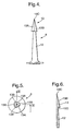
- each spike 8 is machined to define a shaft 12 tipped with a sharply pointed, generally pyramidal barb 13. More particularly the barb 13 is polygonal in planform, being machined from a solid cone to provide three major flat faces 13A between three minor frustoconical faces 13B with a common vertex 13C, and is undercut at its base as indicated at 13D in Figure 6. This form of barb with flats 13A machined into a cone has been found to require less force to penetrate conventional tyre rubber than the equivalent plain cone.
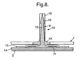
- FIGs 7 and 8 show the relationship of the net 1, spike assemblies 10 and leading edge strip 2.
- a spike 8 located at each alternate knot across the width of the net 1, with the two rows laterally offset from each other by one knot.
- the spikes are held on the strip 2 at the correct spacing by multiple hook and loop contact fastener material such as that known under the registered trade mark Velcro.
- Lengths of Velcro ® hook material 14 ( Figure 8) are sewn to the leading edge strip 2 where the two rows of spikes are required and the spike assemblies 10 are attached by respective pads of Velcro ® loop material 15 passing over the spike assembly bases 11 and into contact with the hook material 14, the pads 15 being apertured to pass the spikes 8.
- Holes 16 and 17 are shown cut through the material of the strip 2 and (in the case of holes 17) through the associated Velcro ® fasteners in Figures 1 and 7 to reduce both the weight of the overall assembly and any aerodynamic forces due to wind acting on the leading edge of the device when deployed.
- spike assemblies 10 Having attached the spike assemblies 10 to the leading edge strip 2 they are assembled with the net 1 by thrusting the barb 13 of each spike through the respective knot of the net and passing the knot down to engage frictionally around its shaft 12, as shown for the knot 1 A in Figure 8.
- a plastics tube 18 is passed over the exposed length of each spike 8 to resist lifting of the net along the shaft 12 and to prevent the barb 13 snagging on the net when it is folded for storage and transportation.
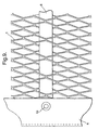
- Figure 9 shows the relationship of the intermediate strip 6, net 1 and side strip 4, the equivalent applying to the opposite side strip 5 and for the trailing edge strip 3 and other intermediate strip 7.
- the strip 6 comprises a length of webbing which is threaded through loops of the net 1 across its width as illustrated.
- the respective strip 4 or 5 is folded over the net 1 and over the ends of the strips 2 (see also Figure 7), 3, 6 and 7, and glued thereto.
- rivets 19 are applied, passing through the material of the respective strips and a local loop of the net.
- the side strips 4 and 5 are apertured to pass the outermost spikes 8A, 8B in each row, as shown for the strip 5 in Figure 7.
- the illustrated device is designed to be man-portable and is normally kept folded in an appropriate backpack, from which it can rapidly be unfolded and deployed across a roadway when a target vehicle is to be arrested.
- the net 1 has sufficient lateral stretch to absorb the loads that are imposed on it as it pulls tight to arrest a vehicle, and to allow the net to become fully wrapped around the front wheels before the tension builds up to a level at which there might otherwise be a risk of the spikes 8 being pulled from the tyres.
- the loops of the net are in a diamond shape with the longer dimension in the fore and aft direction. It is therefore capable of significant lateral elongation before the loops are pulled to a condition in which their longer dimension is in the transverse direction and the net begins to tighten.
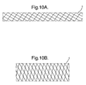
- the "natural" form of the loops in which the net is originally woven is rectangular with the longer dimension in the transverse direction, as schematically depicted in Figure 10(a) (where the size of the loops is greatly exaggerated in relation to the overall size of the net for ease of illustration),
- the net is pulled out of the "natural" shape of Figure 10(a) and held in a jig in the less elongate aspect ratio schematically depicted in Figure 10(b) in which it is subsequently retained by the attachment of the strips 2 to 7.
- the device can operate to arrest a vehicle as described above so long as both front tyres run over its leading edge, irrespective of the position across the width of the device where this actually occurs.
- its leading edge may be formed with a series of short longitudinal cuts spaced across its width, as schematically indicated at 1 B in Figure 1.
Landscapes
- Engineering & Computer Science (AREA)
- Architecture (AREA)
- Civil Engineering (AREA)
- Structural Engineering (AREA)
- Refuge Islands, Traffic Blockers, Or Guard Fence (AREA)
- Road Paving Structures (AREA)
- Tires In General (AREA)
- Vehicle Body Suspensions (AREA)
- Harvester Elements (AREA)
- Braking Arrangements (AREA)
- Window Of Vehicle (AREA)
- Diaphragms For Electromechanical Transducers (AREA)
- Automobile Manufacture Line, Endless Track Vehicle, Trailer (AREA)
Claims (16)
- Vorrichtung zum Aufhalten eines Fahrzeugs, die ein Netz (1) umfasst, das ausgebildet ist, flach auf den Boden und in den Weg eines aufzuhaltenden Fahrzeugs gelegt zu werden, wobei an einem vorderen Abschnitt des Netzes (1) eine oder mehrere quer verlaufende Reihen von nach oben gerichteten Dornen (8) angebracht sind,
dadurch gekennzeichnet, dass die Maschen des Netzes (1) so deformiert sind, dass ihre Abmessungen in Richtung von Vorne nach Hinten länger als quer dazu sind, wodurch jeder Breitenabschnitt des Netzes (1) beim Einsatz beträchtlich in Querrichtung gedehnt werden kann. - Vorrichtung nach Anspruch 1, worin die Dorne (8) mit allgemein pyramidenförmigen Spitzen (13) bestückt sind.
- Vorrichtung nach Anspruch 2, worin die Spitzen (13) mehrere von stumpfkegelförmigen Seitenflächen (13B) voneinander getrennte abgeflachte dreieckförmige Seitenflächen (13A) aufweisen.
- Vorrichtung nach Anspruch 2 oder 3, worin die Spitzen (13) an ihren Grundflächen hinterschnitten (13D) sind.
- Vorrichtung nach einem der vorangehenden Ansprüche, worin die Dorne (8) in Dornenbaugruppen (10) aufgenommen sind, die einen Fußbereich (11), mittels dessen der jeweilige Dorn (8) in einer aufwärts gerichteten Ausrichtung aufgestellt werden kann, einen Schaftbereich (12), der sich vom Fußbereich (11) aus erstreckt, und an der Spitze des Schaftbereichs (12) einen Spitzenbereich (13) umfassen.
- Vorrichtung nach einem der vorangehenden Ansprüche, die mehrere längliche Elemente (2, 3, 5, 7) aus einem elastischen Material aufweist, die sich an zueinander beabstandeten Stellen quer über das Netz (1) erstrecken und an gegenüberliegenden Seitenkanten an dem Netz befestigt sind.
- Vorrichtung nach Anspruch 6, worin zwischen den Seitenkanten eines oder mehrere der länglichen Elemente (3, 6, 7) durch Maschen des Netzes (1) gefädelt, wobei diese an den Seitenkanten jedoch formschlüssig (19) am Netz (1) befestigt sind.
- Vorrichtung nach Anspruch 6 oder 7, worin zwischen den Seitenkanten eines oder mehrere der länglichen Elemente (2) mithilfe von trennbaren Klettverschlüssen (14, 15) am Netz (1) gehalten werden, wobei diese an den Seitenkanten jedoch formschlüssig (8A, 8B) am Netz (1) befestigt sind.
- Vorrichtung nach einem der Ansprüche 6 bis 8 soweit auf Anspruch 5 zurückbezogen, worin die Dornenbaugruppen (10) an einer Vorderkante des Netzes (1) mittels eines trennbaren Klettverschlusses (14, 15) an einem länglichen Element (2) befestigt sind, und Elemente des Klettverschlusses (14, 15) in die jeweiligen dazwischen liegenden Fußbereiche (11) der Dornenbaugruppen (10) eingreifen.
- Vorrichtung nach Anspruch 5 oder nach einem anderen auf Anspruch 5 zurückbezogenen Anspruch, worin die Dornenbaugruppen (10) an dem Netz (1) befestigt sind, indem sie durch entsprechende Bereiche (1A) des Netzes (1) so hindurch reichen, dass das sich das Material des Netzes (1) um die Schaftbereiche (12) dieser Baugruppen (10) legt.
- Vorrichtung nach einem der vorangehenden Ansprüche, worin die Dorne (8) von entsprechenden zum Zerdrücken ausgebildeten Röhren (18) umgeben sind, die das Eindringen des jeweiligen Dorns (8) in einen beim Einsatz der Vorrichtung über solche Dorne (8) fahrender Fahrzeugreifen ermöglichen.
- Vorrichtung nach einem der vorangehenden Ansprüche, worin im vorderen Bereich des Netzes (1) entlang dessen Breite mehrere voneinander getrennte Abschnitte ausgebildet sind.
- Verfahren zum Herstellen einer Vorrichtung zum Aufhalten eines Fahrzeugs nach einem der vorangehenden Ansprüche, wobei dieses umfasst: Hernehmen und Deformieren eines Netzes (1), um dessen Maschen in der bestimmungsgemäßen Längsrichtung der Vorrichtung zu strecken und die Abmessungen des Netzes (1) in der bestimmungsgemäß transversalen Richtung zu reduzieren, Anbringen von länglichen Elementen (2, 3, 6, 7) aus einem elastischen Material zwischen gegenüberliegenden Seitenkanten des Netzes (1), wobei das Netz in dem so deformierte Zustand fixiert ist, wenn es in Vorbereitung zum Aufhalten eines Fahrzeugs auf den Boden gelegt wird.
- Verfahren nach Anspruch 13, das zwischen den Seitenkanten ein Einfädeln von einem oder mehreren der länglichen Elemente (3, 6, 7) durch die Maschen des Netzes (1), an den Seitenkanten jedoch ein formschlüssiges (19) Befestigen solcher Elemente (3, 6,7) am Netz (1) umfasst.
- Verfahren nach Anspruch 13 oder 14, das zwischen den Seitenkanten ein Befestigen von einem oder mehreren der länglichen Elemente (2) am Netz (1) mithilfe von trennbaren Klettverschlüssen (14, 15), an den Seitenkanten jedoch ein formschlüssiges Anbringen (8A, 8B) solcher Elemente (2) am Netz (1) umfasst.
- Verfahren zum Aufhalten eines Fahrzeugs, bei dem eine Vorrichtung nach einem der Ansprüche 1 bis 11 so auf den Boden und in den Weg eines Fahrzeugs gelegt wird, dass, wenn die Vorderräder des Fahrzeugs den vorderen Abschnitt der Vorrichtung überfahren, in jeden der Reifen einer oder mehrere der Dornen (8) eindringen und sich das Netz (1) um die Vorderräder des Fahrzeugs wickelt, wobei sich dessen Abschnitt zwischen den Fahrzeugrädern unterhalb des Fahrzeugs strafft und dabei ein weiteres Drehen dieser Räder unterbindet.
Priority Applications (1)
| Application Number | Priority Date | Filing Date | Title |
|---|---|---|---|
| EP07017697A EP1873315B1 (de) | 2003-02-12 | 2004-01-08 | Fahrzeugblockiervorrichtung |
Applications Claiming Priority (3)
| Application Number | Priority Date | Filing Date | Title |
|---|---|---|---|
| GBGB0303119.2A GB0303119D0 (en) | 2003-02-12 | 2003-02-12 | Vehicle arresting device |
| GB0303119 | 2003-02-12 | ||
| PCT/GB2004/000048 WO2004072382A1 (en) | 2003-02-12 | 2004-01-08 | Vehicle arresting device |
Related Child Applications (1)
| Application Number | Title | Priority Date | Filing Date |
|---|---|---|---|
| EP07017697A Division EP1873315B1 (de) | 2003-02-12 | 2004-01-08 | Fahrzeugblockiervorrichtung |
Publications (2)
| Publication Number | Publication Date |
|---|---|
| EP1592844A1 EP1592844A1 (de) | 2005-11-09 |
| EP1592844B1 true EP1592844B1 (de) | 2007-10-10 |
Family
ID=9952827
Family Applications (2)
| Application Number | Title | Priority Date | Filing Date |
|---|---|---|---|
| EP07017697A Expired - Lifetime EP1873315B1 (de) | 2003-02-12 | 2004-01-08 | Fahrzeugblockiervorrichtung |
| EP04700723A Expired - Lifetime EP1592844B1 (de) | 2003-02-12 | 2004-01-08 | Fahrzeugblockiervorrichtung |
Family Applications Before (1)
| Application Number | Title | Priority Date | Filing Date |
|---|---|---|---|
| EP07017697A Expired - Lifetime EP1873315B1 (de) | 2003-02-12 | 2004-01-08 | Fahrzeugblockiervorrichtung |
Country Status (7)
| Country | Link |
|---|---|
| US (2) | US7862251B2 (de) |
| EP (2) | EP1873315B1 (de) |
| AT (2) | ATE375418T1 (de) |
| DE (2) | DE602004009409T2 (de) |
| GB (1) | GB0303119D0 (de) |
| IL (2) | IL170247A (de) |
| WO (1) | WO2004072382A1 (de) |
Families Citing this family (36)
| Publication number | Priority date | Publication date | Assignee | Title |
|---|---|---|---|---|
| GB0303119D0 (en) * | 2003-02-12 | 2003-03-19 | Qinetiq Ltd | Vehicle arresting device |
| IL161133A0 (en) * | 2004-03-28 | 2004-09-27 | Israel Aircraft Ind Ltd | Vehicle arrestor system and spike therefor |
| US8561516B2 (en) * | 2006-02-21 | 2013-10-22 | Engineering Science Analysis Corporation | System and method for non-lethal vehicle restraint |
| US8245617B2 (en) * | 2007-08-07 | 2012-08-21 | Engineering Science Analysis Corporation | Non-lethal restraint device with diverse deployability applications |
| US8601928B2 (en) * | 2007-08-07 | 2013-12-10 | Engineering Science Analysis Corp. | Restraint device for use in an aquatic environment |
| US7882775B2 (en) * | 2007-08-07 | 2011-02-08 | Engineering Science Analysis Corporation | Non-lethal restraint device with diverse deployability applications |
| GB0800900D0 (en) * | 2008-01-18 | 2008-02-27 | Qinetiq Ltd | Vehicle arresting device |
| GB0810021D0 (en) * | 2008-06-02 | 2008-07-09 | Qinetiq Ltd | Apparatus and method for deploying a vehicle arrestign device |
| GB0811340D0 (en) * | 2008-06-20 | 2008-07-30 | Qinetiq Ltd | Vehicle arresting device |
| US8469627B2 (en) * | 2008-09-29 | 2013-06-25 | Pacific Scientific Energetic Materials Company (Arizona), Llc | Apparatuses, systems and methods for selectively affecting movement of a motor vehicle |
| WO2010037140A1 (en) | 2008-09-29 | 2010-04-01 | Pacific Scientific Energetic Materials Company | Apparatuses, systems and methods for selectively affecting movement of a motor vehicle |
| US8517625B2 (en) | 2008-10-06 | 2013-08-27 | Pacific Scientific Energetic Materials Company (Arizona), Llc | Apparatus and method for disabling a ground engaging traction device of a land vehicle |
| US9103082B2 (en) | 2008-10-06 | 2015-08-11 | Pacific Scientific Energetic Materials Company (Arizona) LLC | Apparatus and method for rapidly deflating tires to disable a land vehicle |
| US7997825B2 (en) * | 2008-10-06 | 2011-08-16 | Pacific Scientific Energetic Materials Corporation | Apparatus and method for disabling a ground engaging traction device of a land vehicle |
| US8066446B2 (en) * | 2008-10-06 | 2011-11-29 | Pacific Scientific Energetic Materials Company | Apparatus and method for disabling a ground engaging traction device of a land vehicle |
| US8147163B2 (en) * | 2009-01-15 | 2012-04-03 | Exponent, Inc. | Tire rapid entanglement and arresting device |
| KR100955309B1 (ko) * | 2009-05-04 | 2010-04-30 | 주식회사 현무 | 차량 도주방지용 바리케이트장치 |
| US20120121336A1 (en) * | 2010-05-20 | 2012-05-17 | Tomasz Arciszewski | Barriers and Methods Thereof |
| CN102174799A (zh) * | 2011-03-25 | 2011-09-07 | 阮成堂 | 一种车辆阻拦装置 |
| WO2015035090A1 (en) * | 2013-09-04 | 2015-03-12 | Pacific Scientific Energetic Materials Company (Arizona) LLC | Apparatus to rapidly immobilizing a land vehicle |
| US8858113B1 (en) * | 2014-01-23 | 2014-10-14 | Leonard Jon Bettendorf | Tire deflation device for puncturing one or more tires of a fleeing vehicle |
| US10301786B2 (en) * | 2015-03-23 | 2019-05-28 | Pacific Scientific Energetic Materials Company (California) LLC | Deployable device having an unrolled configuration for rapid, bi-directional immobilization of a targeted vehicle traveling on a roadway, and associated methods |
| US20160281307A1 (en) * | 2015-03-23 | 2016-09-29 | Pacific Scientific Energetic Materials Company (California) LLC | Deployable Device Having An Unrolled Configuration For Rapidly Immobilizing A Land Vehicle And Associated Methods |
| CN104988866B (zh) * | 2015-06-25 | 2017-08-22 | 山东创安交通预警工程有限公司 | 汽车智能拦截装置 |
| US10024008B2 (en) * | 2015-11-10 | 2018-07-17 | The United States Of America As Represented By The Secretary Of The Army | Expedient barrier apparatus |
| EP3417110B1 (de) * | 2016-02-18 | 2020-09-23 | Yoav Barzilai | Vorrichtung für aufprallfreies anhalten von fahrzeugen |
| US10370807B2 (en) * | 2016-11-17 | 2019-08-06 | Off The Wall Products, Llc | Collapsible perimeter barricade |
| US10030343B1 (en) | 2017-01-25 | 2018-07-24 | Ethan Spencer | Vehicle arresting device and method |
| US10576869B2 (en) * | 2017-01-26 | 2020-03-03 | Ford Global Technologies, Llc | Self-retractable cargo net |
| IT201700103533A1 (it) * | 2017-09-15 | 2019-03-15 | C D N Compagnia Del Nord S R L | Sistema per il bloccaggio di autoveicoli in movimento |
| GB202001705D0 (en) | 2020-02-07 | 2020-03-25 | Synbiosys Ltd | A vehicle arrest device |
| CN112962491B (zh) * | 2021-02-09 | 2022-03-01 | 四川九洲电器集团有限责任公司 | 一种阻车装置 |
| CN113026616A (zh) * | 2021-02-26 | 2021-06-25 | 上海仪耐新材料科技有限公司 | 一种全断面电控阻车装置 |
| CN115233591B (zh) * | 2022-06-24 | 2023-06-13 | 西南石油大学 | 一种车辆逼停装置 |
| AU2023338804A1 (en) * | 2022-09-08 | 2025-03-20 | Peter Duncan WHITFORD | Vehicle mitigation system |
| CN116591757A (zh) * | 2023-04-27 | 2023-08-15 | 中铁十七局集团第一工程有限公司 | 一种斜井内防溜车柔性拦阻装置及方法 |
Family Cites Families (22)
| Publication number | Priority date | Publication date | Assignee | Title |
|---|---|---|---|---|
| FR2463056A1 (fr) | 1979-08-09 | 1981-02-20 | Aerazur Constr Aeronaut | Dispositif pour le relevage du filet d'une barriere pour l'arret des avions |
| US4596731A (en) * | 1984-09-17 | 1986-06-24 | Cudmore Warner J G | Grass protecting walkway grid |
| CH673045A5 (de) | 1987-02-23 | 1990-01-31 | Dormet Doerfliger Metallwaren | |
| US4759655A (en) * | 1987-06-16 | 1988-07-26 | Flexible Barricades Inc. | Terrorist vehicle arresting system |
| US5310277A (en) * | 1988-11-22 | 1994-05-10 | Arrestarum Ltd. | Means and net for slowing down and/or stopping the motion of a land vehicle |
| US5634738A (en) * | 1995-10-27 | 1997-06-03 | Jackson; Martin A. | Vehicle arresting system |
| EP0857237A4 (de) * | 1995-10-27 | 1999-03-03 | Entwistle Co | Energieabsorbierende mehrzweck barriere |
| US5624203A (en) * | 1995-10-27 | 1997-04-29 | The Entwistle Company | Energy absorbing barrier system with crash indication |
| US6312188B1 (en) * | 1996-06-27 | 2001-11-06 | General Dynamics Ordnance And Tactical Systems, Inc. | Non-lethal, rapidly deployed vehicle immobilizer |
| US5829912A (en) * | 1996-06-27 | 1998-11-03 | Primex Technologies, Inc. | Non-lethal, rapidly deployed, vehicle immobilizer system |
| JPH1136249A (ja) * | 1997-07-15 | 1999-02-09 | Japan Aircraft Mfg Co Ltd | 車両阻止用ネット |
| US6220781B1 (en) | 1998-10-13 | 2001-04-24 | Purple & Green Research, Inc. | Vehicle stopping device |
| US6312189B1 (en) * | 1999-05-18 | 2001-11-06 | Toranj Marphetia | Vehicle tire puncturing and deflating spike and assembly therefor |
| IL131073A0 (en) * | 1999-07-23 | 2001-01-28 | Yossi Ben | A removable vehicle barrier |
| US6997637B2 (en) * | 2000-12-06 | 2006-02-14 | The United States Of America As Represented By The National Aeronautics And Space Administration | Deceleration-limiting roadway barrier |
| US6409420B1 (en) | 2001-07-02 | 2002-06-25 | The United States Of America As Represented By The Secretary Of The Navy | Portable vehicle barrier |
| CA2393380A1 (en) | 2002-08-01 | 2002-12-08 | Ace R. Collier | Automobile wheel and track snare |
| GB0303119D0 (en) | 2003-02-12 | 2003-03-19 | Qinetiq Ltd | Vehicle arresting device |
| IL177763A0 (en) * | 2006-08-29 | 2007-03-08 | Iftach Segal | Method and device for arresting a vehicle |
| GB0800900D0 (en) * | 2008-01-18 | 2008-02-27 | Qinetiq Ltd | Vehicle arresting device |
| GB0811340D0 (en) * | 2008-06-20 | 2008-07-30 | Qinetiq Ltd | Vehicle arresting device |
| US8147163B2 (en) * | 2009-01-15 | 2012-04-03 | Exponent, Inc. | Tire rapid entanglement and arresting device |
-
2003
- 2003-02-12 GB GBGB0303119.2A patent/GB0303119D0/en not_active Ceased
-
2004
- 2004-01-08 EP EP07017697A patent/EP1873315B1/de not_active Expired - Lifetime
- 2004-01-08 EP EP04700723A patent/EP1592844B1/de not_active Expired - Lifetime
- 2004-01-08 US US10/544,297 patent/US7862251B2/en not_active Expired - Lifetime
- 2004-01-08 AT AT04700723T patent/ATE375418T1/de not_active IP Right Cessation
- 2004-01-08 DE DE602004009409T patent/DE602004009409T2/de not_active Expired - Lifetime
- 2004-01-08 WO PCT/GB2004/000048 patent/WO2004072382A1/en not_active Ceased
- 2004-01-08 DE DE602004019998T patent/DE602004019998D1/de not_active Expired - Lifetime
- 2004-01-08 AT AT07017697T patent/ATE425310T1/de not_active IP Right Cessation
-
2005
- 2005-08-11 IL IL170247A patent/IL170247A/en active IP Right Grant
-
2008
- 2008-10-05 IL IL194527A patent/IL194527A/en active IP Right Grant
-
2010
- 2010-11-22 US US12/951,663 patent/US8202019B2/en not_active Expired - Lifetime
Also Published As
| Publication number | Publication date |
|---|---|
| US7862251B2 (en) | 2011-01-04 |
| IL170247A (en) | 2009-09-01 |
| US20060140715A1 (en) | 2006-06-29 |
| DE602004009409T2 (de) | 2008-02-07 |
| EP1873315B1 (de) | 2009-03-11 |
| US20110064516A1 (en) | 2011-03-17 |
| DE602004009409D1 (de) | 2007-11-22 |
| WO2004072382A1 (en) | 2004-08-26 |
| US8202019B2 (en) | 2012-06-19 |
| IL194527A (en) | 2011-04-28 |
| ATE425310T1 (de) | 2009-03-15 |
| GB0303119D0 (en) | 2003-03-19 |
| EP1592844A1 (de) | 2005-11-09 |
| ATE375418T1 (de) | 2007-10-15 |
| EP1873315A1 (de) | 2008-01-02 |
| DE602004019998D1 (de) | 2009-04-23 |
Similar Documents
| Publication | Publication Date | Title |
|---|---|---|
| EP1592844B1 (de) | Fahrzeugblockiervorrichtung | |
| US7736086B2 (en) | Vehicle arresting device | |
| US20100284739A1 (en) | Vehicle Arresting Device | |
| US5322385A (en) | Anti-vehicle barrier | |
| US7785032B2 (en) | Arresting motion of a vehicle having wheels with tires | |
| US5310277A (en) | Means and net for slowing down and/or stopping the motion of a land vehicle | |
| US9200417B2 (en) | Guardrail system with a releasable post | |
| JP6057714B2 (ja) | 自動車の動きに選択的に影響を及ぼすための装置、システム、及び方法 | |
| US9702100B2 (en) | Apparatuses, systems and methods for selectively affecting movement of a motor vehicle | |
| US6220781B1 (en) | Vehicle stopping device | |
| WO2009147363A1 (en) | Apparatus and method for deploying a vehicle arresting device | |
| US9982403B2 (en) | Vehicle barrier apparatus | |
| US7226238B2 (en) | Automobile wheel and track snare | |
| US6997637B2 (en) | Deceleration-limiting roadway barrier | |
| WO2005093163A2 (en) | Vehicle arrester systems | |
| CN105672168A (zh) | 一种阻车系统 | |
| CN104294779B (zh) | 网钉结合的阻车系统 | |
| EP3417110B1 (de) | Vorrichtung für aufprallfreies anhalten von fahrzeugen | |
| GB2232431A (en) | Road vehicle arrestor | |
| CN204589864U (zh) | 一种组合式柔性阻车网 | |
| CN105714712A (zh) | 电驱控制阻车系统 | |
| EP1757735A2 (de) | Nicht lethales, schnell entfaltetes Fahrzeugimmobilisationssystem |
Legal Events
| Date | Code | Title | Description |
|---|---|---|---|
| PUAI | Public reference made under article 153(3) epc to a published international application that has entered the european phase |
Free format text: ORIGINAL CODE: 0009012 |
|
| 17P | Request for examination filed |
Effective date: 20050723 |
|
| AK | Designated contracting states |
Kind code of ref document: A1 Designated state(s): AT BE BG CH CY CZ DE DK EE ES FI FR GB GR HU IE IT LI LU MC NL PT RO SE SI SK TR |
|
| AX | Request for extension of the european patent |
Extension state: AL LT LV MK |
|
| DAX | Request for extension of the european patent (deleted) | ||
| 17Q | First examination report despatched |
Effective date: 20060324 |
|
| GRAP | Despatch of communication of intention to grant a patent |
Free format text: ORIGINAL CODE: EPIDOSNIGR1 |
|
| GRAS | Grant fee paid |
Free format text: ORIGINAL CODE: EPIDOSNIGR3 |
|
| GRAA | (expected) grant |
Free format text: ORIGINAL CODE: 0009210 |
|
| AK | Designated contracting states |
Kind code of ref document: B1 Designated state(s): AT BE BG CH CY CZ DE DK EE ES FI FR GB GR HU IE IT LI LU MC NL PT RO SE SI SK TR |
|
| REG | Reference to a national code |
Ref country code: GB Ref legal event code: FG4D |
|
| REG | Reference to a national code |
Ref country code: CH Ref legal event code: EP |
|
| REG | Reference to a national code |
Ref country code: IE Ref legal event code: FG4D |
|
| REF | Corresponds to: |
Ref document number: 602004009409 Country of ref document: DE Date of ref document: 20071122 Kind code of ref document: P |
|
| PG25 | Lapsed in a contracting state [announced via postgrant information from national office to epo] |
Ref country code: CH Free format text: LAPSE BECAUSE OF FAILURE TO SUBMIT A TRANSLATION OF THE DESCRIPTION OR TO PAY THE FEE WITHIN THE PRESCRIBED TIME-LIMIT Effective date: 20071010 Ref country code: SE Free format text: LAPSE BECAUSE OF FAILURE TO SUBMIT A TRANSLATION OF THE DESCRIPTION OR TO PAY THE FEE WITHIN THE PRESCRIBED TIME-LIMIT Effective date: 20080110 Ref country code: LI Free format text: LAPSE BECAUSE OF FAILURE TO SUBMIT A TRANSLATION OF THE DESCRIPTION OR TO PAY THE FEE WITHIN THE PRESCRIBED TIME-LIMIT Effective date: 20071010 Ref country code: ES Free format text: LAPSE BECAUSE OF FAILURE TO SUBMIT A TRANSLATION OF THE DESCRIPTION OR TO PAY THE FEE WITHIN THE PRESCRIBED TIME-LIMIT Effective date: 20080121 |
|
| REG | Reference to a national code |
Ref country code: CH Ref legal event code: PL |
|
| PG25 | Lapsed in a contracting state [announced via postgrant information from national office to epo] |
Ref country code: PT Free format text: LAPSE BECAUSE OF FAILURE TO SUBMIT A TRANSLATION OF THE DESCRIPTION OR TO PAY THE FEE WITHIN THE PRESCRIBED TIME-LIMIT Effective date: 20080310 Ref country code: BG Free format text: LAPSE BECAUSE OF FAILURE TO SUBMIT A TRANSLATION OF THE DESCRIPTION OR TO PAY THE FEE WITHIN THE PRESCRIBED TIME-LIMIT Effective date: 20080110 |
|
| PG25 | Lapsed in a contracting state [announced via postgrant information from national office to epo] |
Ref country code: AT Free format text: LAPSE BECAUSE OF FAILURE TO SUBMIT A TRANSLATION OF THE DESCRIPTION OR TO PAY THE FEE WITHIN THE PRESCRIBED TIME-LIMIT Effective date: 20071010 |
|
| ET | Fr: translation filed | ||
| PG25 | Lapsed in a contracting state [announced via postgrant information from national office to epo] |
Ref country code: DK Free format text: LAPSE BECAUSE OF FAILURE TO SUBMIT A TRANSLATION OF THE DESCRIPTION OR TO PAY THE FEE WITHIN THE PRESCRIBED TIME-LIMIT Effective date: 20071010 Ref country code: CZ Free format text: LAPSE BECAUSE OF FAILURE TO SUBMIT A TRANSLATION OF THE DESCRIPTION OR TO PAY THE FEE WITHIN THE PRESCRIBED TIME-LIMIT Effective date: 20071010 |
|
| PLBE | No opposition filed within time limit |
Free format text: ORIGINAL CODE: 0009261 |
|
| STAA | Information on the status of an ep patent application or granted ep patent |
Free format text: STATUS: NO OPPOSITION FILED WITHIN TIME LIMIT |
|
| PG25 | Lapsed in a contracting state [announced via postgrant information from national office to epo] |
Ref country code: BE Free format text: LAPSE BECAUSE OF FAILURE TO SUBMIT A TRANSLATION OF THE DESCRIPTION OR TO PAY THE FEE WITHIN THE PRESCRIBED TIME-LIMIT Effective date: 20071010 Ref country code: SK Free format text: LAPSE BECAUSE OF FAILURE TO SUBMIT A TRANSLATION OF THE DESCRIPTION OR TO PAY THE FEE WITHIN THE PRESCRIBED TIME-LIMIT Effective date: 20071010 Ref country code: RO Free format text: LAPSE BECAUSE OF FAILURE TO SUBMIT A TRANSLATION OF THE DESCRIPTION OR TO PAY THE FEE WITHIN THE PRESCRIBED TIME-LIMIT Effective date: 20071010 Ref country code: MC Free format text: LAPSE BECAUSE OF NON-PAYMENT OF DUE FEES Effective date: 20080131 |
|
| 26N | No opposition filed |
Effective date: 20080711 |
|
| PG25 | Lapsed in a contracting state [announced via postgrant information from national office to epo] |
Ref country code: GR Free format text: LAPSE BECAUSE OF FAILURE TO SUBMIT A TRANSLATION OF THE DESCRIPTION OR TO PAY THE FEE WITHIN THE PRESCRIBED TIME-LIMIT Effective date: 20080111 Ref country code: EE Free format text: LAPSE BECAUSE OF FAILURE TO SUBMIT A TRANSLATION OF THE DESCRIPTION OR TO PAY THE FEE WITHIN THE PRESCRIBED TIME-LIMIT Effective date: 20071010 Ref country code: IE Free format text: LAPSE BECAUSE OF NON-PAYMENT OF DUE FEES Effective date: 20080108 |
|
| PG25 | Lapsed in a contracting state [announced via postgrant information from national office to epo] |
Ref country code: FI Free format text: LAPSE BECAUSE OF FAILURE TO SUBMIT A TRANSLATION OF THE DESCRIPTION OR TO PAY THE FEE WITHIN THE PRESCRIBED TIME-LIMIT Effective date: 20071010 |
|
| PG25 | Lapsed in a contracting state [announced via postgrant information from national office to epo] |
Ref country code: SI Free format text: LAPSE BECAUSE OF FAILURE TO SUBMIT A TRANSLATION OF THE DESCRIPTION OR TO PAY THE FEE WITHIN THE PRESCRIBED TIME-LIMIT Effective date: 20071010 |
|
| PG25 | Lapsed in a contracting state [announced via postgrant information from national office to epo] |
Ref country code: CY Free format text: LAPSE BECAUSE OF FAILURE TO SUBMIT A TRANSLATION OF THE DESCRIPTION OR TO PAY THE FEE WITHIN THE PRESCRIBED TIME-LIMIT Effective date: 20071010 |
|
| PGFP | Annual fee paid to national office [announced via postgrant information from national office to epo] |
Ref country code: FR Payment date: 20100223 Year of fee payment: 7 |
|
| PGFP | Annual fee paid to national office [announced via postgrant information from national office to epo] |
Ref country code: DE Payment date: 20100121 Year of fee payment: 7 |
|
| PG25 | Lapsed in a contracting state [announced via postgrant information from national office to epo] |
Ref country code: HU Free format text: LAPSE BECAUSE OF FAILURE TO SUBMIT A TRANSLATION OF THE DESCRIPTION OR TO PAY THE FEE WITHIN THE PRESCRIBED TIME-LIMIT Effective date: 20080411 Ref country code: LU Free format text: LAPSE BECAUSE OF NON-PAYMENT OF DUE FEES Effective date: 20080108 |
|
| PG25 | Lapsed in a contracting state [announced via postgrant information from national office to epo] |
Ref country code: TR Free format text: LAPSE BECAUSE OF FAILURE TO SUBMIT A TRANSLATION OF THE DESCRIPTION OR TO PAY THE FEE WITHIN THE PRESCRIBED TIME-LIMIT Effective date: 20071010 |
|
| PGFP | Annual fee paid to national office [announced via postgrant information from national office to epo] |
Ref country code: NL Payment date: 20100118 Year of fee payment: 7 |
|
| PG25 | Lapsed in a contracting state [announced via postgrant information from national office to epo] |
Ref country code: IT Free format text: LAPSE BECAUSE OF NON-PAYMENT OF DUE FEES Effective date: 20080131 |
|
| REG | Reference to a national code |
Ref country code: NL Ref legal event code: V1 Effective date: 20110801 |
|
| REG | Reference to a national code |
Ref country code: FR Ref legal event code: ST Effective date: 20110930 |
|
| PG25 | Lapsed in a contracting state [announced via postgrant information from national office to epo] |
Ref country code: FR Free format text: LAPSE BECAUSE OF NON-PAYMENT OF DUE FEES Effective date: 20110131 |
|
| PG25 | Lapsed in a contracting state [announced via postgrant information from national office to epo] |
Ref country code: NL Free format text: LAPSE BECAUSE OF NON-PAYMENT OF DUE FEES Effective date: 20110801 |
|
| REG | Reference to a national code |
Ref country code: DE Ref legal event code: R119 Ref document number: 602004009409 Country of ref document: DE Effective date: 20110802 |
|
| PG25 | Lapsed in a contracting state [announced via postgrant information from national office to epo] |
Ref country code: DE Free format text: LAPSE BECAUSE OF NON-PAYMENT OF DUE FEES Effective date: 20110802 |
|
| PGFP | Annual fee paid to national office [announced via postgrant information from national office to epo] |
Ref country code: GB Payment date: 20230127 Year of fee payment: 20 |
|
| P01 | Opt-out of the competence of the unified patent court (upc) registered |
Effective date: 20230401 |
|
| REG | Reference to a national code |
Ref country code: GB Ref legal event code: PE20 Expiry date: 20240107 |
|
| PG25 | Lapsed in a contracting state [announced via postgrant information from national office to epo] |
Ref country code: GB Free format text: LAPSE BECAUSE OF EXPIRATION OF PROTECTION Effective date: 20240107 |