EP1592109A2 - Vorrichtung und Verfahren zum Einbau eines vormontierten Statorkerns - Google Patents
Vorrichtung und Verfahren zum Einbau eines vormontierten Statorkerns Download PDFInfo
- Publication number
- EP1592109A2 EP1592109A2 EP05009097A EP05009097A EP1592109A2 EP 1592109 A2 EP1592109 A2 EP 1592109A2 EP 05009097 A EP05009097 A EP 05009097A EP 05009097 A EP05009097 A EP 05009097A EP 1592109 A2 EP1592109 A2 EP 1592109A2
- Authority
- EP
- European Patent Office
- Prior art keywords
- container
- stator core
- stator
- power generator
- core
- Prior art date
- Legal status (The legal status is an assumption and is not a legal conclusion. Google has not performed a legal analysis and makes no representation as to the accuracy of the status listed.)
- Granted
Links
- 238000000034 method Methods 0.000 title claims abstract description 32
- 238000009434 installation Methods 0.000 title claims description 4
- 238000003475 lamination Methods 0.000 claims description 31
- 235000012489 doughnuts Nutrition 0.000 claims description 17
- 238000004519 manufacturing process Methods 0.000 description 6
- 229910000831 Steel Inorganic materials 0.000 description 4
- 239000010959 steel Substances 0.000 description 4
- 238000004804 winding Methods 0.000 description 3
- 230000008901 benefit Effects 0.000 description 2
- 239000000306 component Substances 0.000 description 2
- 238000006073 displacement reaction Methods 0.000 description 2
- 239000008358 core component Substances 0.000 description 1
- 230000010339 dilation Effects 0.000 description 1
- 230000005484 gravity Effects 0.000 description 1
- 230000013011 mating Effects 0.000 description 1
- 238000012986 modification Methods 0.000 description 1
- 230000004048 modification Effects 0.000 description 1
- 238000003825 pressing Methods 0.000 description 1
Images

Classifications
-
- H—ELECTRICITY
- H02—GENERATION; CONVERSION OR DISTRIBUTION OF ELECTRIC POWER
- H02K—DYNAMO-ELECTRIC MACHINES
- H02K15/00—Processes or apparatus specially adapted for manufacturing, assembling, maintaining or repairing of dynamo-electric machines
-
- H—ELECTRICITY
- H02—GENERATION; CONVERSION OR DISTRIBUTION OF ELECTRIC POWER
- H02K—DYNAMO-ELECTRIC MACHINES
- H02K15/00—Processes or apparatus specially adapted for manufacturing, assembling, maintaining or repairing of dynamo-electric machines
- H02K15/02—Processes or apparatus specially adapted for manufacturing, assembling, maintaining or repairing of dynamo-electric machines of stator or rotor bodies
-
- Y—GENERAL TAGGING OF NEW TECHNOLOGICAL DEVELOPMENTS; GENERAL TAGGING OF CROSS-SECTIONAL TECHNOLOGIES SPANNING OVER SEVERAL SECTIONS OF THE IPC; TECHNICAL SUBJECTS COVERED BY FORMER USPC CROSS-REFERENCE ART COLLECTIONS [XRACs] AND DIGESTS
- Y10—TECHNICAL SUBJECTS COVERED BY FORMER USPC
- Y10T—TECHNICAL SUBJECTS COVERED BY FORMER US CLASSIFICATION
- Y10T29/00—Metal working
- Y10T29/49—Method of mechanical manufacture
- Y10T29/49002—Electrical device making
- Y10T29/49009—Dynamoelectric machine
- Y10T29/49012—Rotor
-
- Y—GENERAL TAGGING OF NEW TECHNOLOGICAL DEVELOPMENTS; GENERAL TAGGING OF CROSS-SECTIONAL TECHNOLOGIES SPANNING OVER SEVERAL SECTIONS OF THE IPC; TECHNICAL SUBJECTS COVERED BY FORMER USPC CROSS-REFERENCE ART COLLECTIONS [XRACs] AND DIGESTS
- Y10—TECHNICAL SUBJECTS COVERED BY FORMER USPC
- Y10T—TECHNICAL SUBJECTS COVERED BY FORMER US CLASSIFICATION
- Y10T29/00—Metal working
- Y10T29/53—Means to assemble or disassemble
- Y10T29/5313—Means to assemble electrical device
- Y10T29/53143—Motor or generator
Definitions
- the present invention relates to power generators, and more specifically stator cores. More particularly, the invention relates to the transfer of a pre-assembled stator core into stator frame.
- the generator stator core is the largest single component in the train of a turbine generator set.
- the stator cores are generally manufactured from thousands of laminations of relatively thin steel plates which are stacked, pressed and clamped together into the large cylindrical form of the stator core.
- the clamping is necessary to accommodate variations in thickness of the stock steel plate laminations, commonly referred to as crowns. Improperly clamped laminations can result in plate vibration during generator operation, which results from magnetic impulses or core elliptical dilation.
- stator core is assembled from the steel plates directly at the final installation site.
- stator core manufacturing difficulties including generous floor space and high crane requirements.
- the manufacture of stator cores via the traditional methods result in manufacturing lead time and other associated manufacturing difficulties. For example, if the core is stacked directly in the stator frame, the frame must be delivered to the site before any manufacturing steps can occur. Additionally, intermediate core pressing equipment is needed to press and clamp the steel plates together at incremental lengths. If, on the other hand, the stator core is manufactured in an external fixture, the external fixture itself adds to the manufacturing costs and requires additional floor space on site and still requires the use of heavy cranes.
- Keybars are essentially rods that run the internal length of the stator core and provide a hook-in spot for the laminations.
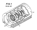
- Fig. 1 illustrates a stator frame that is empty of any laminations.
- the keybars 6 run the internal length of the stator frame 2, and are generally attached to the frame through stator support rings 4.
- the size of laminations and resulting stator core can vary, but a typical stator core lamination has a weight of 3.6 lbs (1.6 kg). The results in a weight per inch of core of 1530 lbs/in (1740 kg/cm). For a core length of 225 inches (563 cm), the total weight will be approximately 344,250 lbs (156,477 kg).
- stator cores into existing generator frames.
- each lamination needs to be stacked into position individually. This is a time consuming process, which is prone to causing imperfections in the stacking of the stator core.
- the present invention reduces these problems by providing a container that holds a pre-assembled stator core.
- the pre-assembled core is shipped to the stator frame in the container.
- the stator core is then transferred to the stator frame by aligning the container with the stator frame and sliding the core into position.
- This method and apparatus may also be used on partially assembled stator cores, and segments of stator cores referred to as donuts.
- the laminations may be assembled within the container itself, or assembled outside of the container and then inserted into it.
- a method of installing a stator core in a power generator that comprises assembling the stator core inside of a container, and then moving the container to the power generator.
- the container is horizontally aligned with the power generator, and the stator core is transferred from the container to the power generator.
- partial stator cores are divided into multiple shipping containers.
- the multiple shipping containers are horizontally aligned at both ends of a stator frame, and the stator core is assembled from both ends of the stator frame.
- the present invention provides for an apparatus for the horizontal placement of a stator core within a stator frame.
- This apparatus comprises a container, and the container comprises an internal space capable of holding the stator core, and multiple keybars arraigned along the internal space capable of securing the stator core within the internal space.
- the container is capable of being aligned with a stator frame and the stator core that is disposed within the container is horizontally transferable to the stator frame.
- the apparatus further comprises keybar extensions, where the keybar extensions bridge the container and the stator frame.
- a central rail structure is provided, where the central rail structure is capable of supporting and aiding in the movement of at least one of laminations, donuts and a stator core within the container.
- the apparatus further comprises both a central rail structure and keybar extensions.
- the apparatus further comprises support rings, where the support rings are capable of applying a radial force to the multiple keybars.
- the apparatus further comprises external hooking members for aiding in the transport of the container.
- donuts and stator cores are capable of being assembled within the container.
- Figure 1 illustrates a typical stator frame with keybars that has not had the stator core yet assembled.
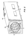
- Figure 2 illustrates a container according to one embodiment of the present invention.
- Figure 3 illustrates a container being aligned with an existing power generator in accordance with one embodiment of the present invention.
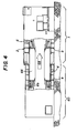
- Figure 4 illustrates the horizontal transfer of a fully assembled stator core from a container to an existing power generator in accordance with one embodiment of the present invention.
- the present invention provides for a method and apparatus for the placement of a pre-assembled stator core into a stator frame using a container.
- the pre-assembled stator core may be fully or partially assembled, and the stator frame may be new, or part of a pre-existing power generator.
- the present invention will also function with stator core segments, referred to as donuts.
- a stator core comprises a plurality of stacked laminations.
- the laminations need to be stacked within a stator frame, and then secured into position by a variety of techniques. Where possible, the stator core is assembled vertically, so that gravity can be used to aid in stacking the core. Additionally, it has been found that pre-assembling some laminations into lamination groups, called donuts, also aids in the stacking of the stator core. It is not always possible, however, to assemble a stator core vertically. For example, existing power generators need to have their stator cores periodically replaced. The old core is removed and the new core needs to be stacked horizontally, since the pre-existing stator frame is immobile. This is an extremely time consuming effort that causes the power generator to be off-line for extended periods of time.
- the present invention allows for a new stator core, either partially or fully assembled, to be shipped to the desired location.
- the container that the stator core is shipped in provides a support structure similar to a stator frame. When on location, the container is aligned with the existing stator frame, and the stator core is slid from the container into the stator frame. The entire stator core may be transferred in this manner, or sections of the core may be transferred at a time.
- the partially assembled core is either contained within a single container, or optionally contained within multiple containers.
- the new stator core comprises multiple donuts divided into multiple containers, the containers may be placed on either side of a stator frame so that the new stator core may be assembled from both sides at the same time.
- stator cores can be placed into the containers ahead of time.
- the pre-assembled core can then be sent to the desired location before the old core is removed, saving vast amounts of time.
- power generators may be modernized more easily as well.
- operators have been reluctant to replace old cores with newer, more efficient cores since such a replacement would mean that the power generators would be off-line for an extended period of time.
- the present invention greatly reduced potential down-time, making such modernizations feasible.
- the present invention is ideally suited for the replacement of old stator cores in pre-existing power generators, it is equally applicable for the assembly of new power generators as well.
- stator cores When stator cores are assembled horizontally, quality is difficult to maintain. This is due to the difficulty of placing the large number of unwieldy laminations properly into position.
- the core is either fully or partially pre-assembled, improving the quality of the new stator core.
- the pre-assembled core can be stacked either inside of or outside of the container. Since the container is mobile, the laminations can be stacked within the container vertically. It may still, however, be desired to stack the stator core outside of the container, and then transfer it to the container for transportation to the stator frame location.
- the container may be aligned by a variety of techniques. For example, a vertical flange on the end of a generator where the bearing brackets are bolted on would have a mating flange on the container that could be bolted to the vertical flange on the generator. Other examples include markings on the container, instruments and other types of physical guides.
- a cable is attached to the stator core that would run through the frame to a turning block on the opposite side.
- An overhead would be used to pull on the cable and the stator core.
- Other methods include a push-pull arrangement, that can be done either manually or hydraulically.
- the push-pull arrangement can use the aid of a beam or other type of physical device. Further, the push-pull arrangement can be an integral part of the container design
- a standard stator frame 2 comprises support rings 4 and keybars 6.
- the keybars 6 engage the outer periphery of the laminations, helping to hold them in position.
- a container 60 is shown.
- the container 60 holds a pre-assembled stator core or portions thereof. Similar to a stator frame, the container has a mechanism for supporting the stator core, in this embodiment it is support rings 4 and keybars 6.
- the container 60 may also have end cover panels (not shown) and access panels 62.
- the access panels 62 can be used to check on the status of the stator core within, and/or to aid in the stacking to the stator core.
- the container may also have hooks or handles 64 to aid in the lifting or tilting of the container.
- stator core or a portion thereof, is assembled or partially assembled within the container
- the entire container is aligned with a power generator, as shown in Fig. 3.
- a container 60 containing a fully assembled stator core is aligned with an existing power generator 1.
- the container 60 is secured against the generator 1 forming a tight seem 61.
- the two are further connected by physical means, such as screws, hooks, dovetailing, temporary welds and similar techniques.
- stator core 66 Referring to Fig. 4, the transfer of a fully assembled stator core 66 is illustrated.
- the core 66 is slid laterally 68 along the keybars 6 in the container 60.
- the core 66 then engages the keybars 6 in the stator frame 2. Once the stator core 66 is fully within the stator frame 2, the container 60 can be removed.
- stator core 66 Advantageous to a fully assembled stator core 66 include that windings 69 and other core components can be pre-assembled with the rest of the core. However, the present invention is also applicable to partially assembled stator cores.
- the core may be partially assembled within a single container, or may be divided into multiple containers.
- the transfer of the core, or portions thereof, from the container to the new stator frame may be accomplished by a variety of techniques. Two of these techniques are detailed in patent applications Horizontal Assembly of Stator Core using Keybar Extensions, by Sargeant et al., and Horizontal Assembly of Stator Core using a Central Rail Structure by Majernik et al., which are incorporated herein by reference. These applications teach methods and apparatus of using central rail structures and keybar extensions to transfer and place laminations and donuts. The central rail structure and the keybar extensions, either independently or in conjunction, may be used with the present invention.
- the present invention provides for a method of installing a stator core in a power generator that comprises assembling the stator core inside of a container, and then moving the container to the power generator.
- the container is horizontally aligned with the power generator, and the stator core is transferred from the container to the power generator.
- stator core is assembled vertically inside of the container. This may be done in a remote location, or on-site.
- the assembled core is a replacement core, and in another embodiment it is an original core for a power generator.
- the container is used to remove an old stator core, and the same or similar container is used to install the replacement core.
- the container has access panels.
- the container has support rings, end covers, and external hooking members. Support rings apply radial force to the keybars inside of the container, forcing the keybars more securely into the laminations inside. End covers protect and contain the core while shipping.
- the container is also provided with external hooking members. These allow for the container to be more easily shipped.
- stator cores are assembled outside of the container, and then placed inside for shipping to the power generator.
- partial stator cores are installed or assembled inside of the container. Partial stator cores refer to anything less and a complete stator core, and include laminations and donuts.
- a stator core refers to a stator core that has a complete allotment of laminations.
- a fully assembled stator core refers to a stator core that has additional elements assembled, such as windings.
- partial stator cores are divided into multiple shipping containers.
- the multiple shipping containers are horizontally aligned at both ends of a stator frame, and the stator core is assembled from both ends of the stator frame.
- keybar extensions provide support for stator cores and/or partial stator cores as they are transferred from the container to the stator frame.
- a central rail structure proves support for stator cores and/or partial stator cores as they are transferred from the container to the stator frame.
- both keybar extensions and a central rail structure are used.
- the present invention provides for an apparatus for the horizontal placement of a stator core within a stator frame.
- This apparatus comprises a container.
- the container comprises an internal space capable of holding the stator core, and multiple keybars arraigned along the internal space capable of securing the stator core within the internal space.
- the container is capable of being aligned with a stator frame and the stator core that is disposed within the container is horizontally transferable to the stator frame.
- the apparatus further comprises keybar extensions, where the keybar extensions bridge the container and the stator frame.
- a central rail structure is provided, where the central rail structure is capable of supporting and aiding in the movement of at least one of laminations, donuts and a stator core within the container.
- the apparatus further comprises both a central rail structure and keybar extensions.
- the apparatus further comprises support rings, where the support rings are capable of applying a radial pressure to the multiple keybars.
- the apparatus further comprises external hooking members for aiding in the transport of the container.
- donuts and stator cores are capable of being assembled within the container.
- the apparatus is capable of receiving a stator core horizontally from a stator frame. In another embodiment the apparatus is capable of receiving partial stator cores from a stator frame.
- stator core Although the present invention is discussed in primarily in terms of use in stator core, the invention is not limited to this, and other areas of art may also benefit. Some of these other areas include, installation of other components such as rotors and end-winding cones.
Landscapes
- Engineering & Computer Science (AREA)
- Manufacturing & Machinery (AREA)
- Power Engineering (AREA)
- Manufacture Of Motors, Generators (AREA)
- Iron Core Of Rotating Electric Machines (AREA)
Applications Claiming Priority (4)
| Application Number | Priority Date | Filing Date | Title |
|---|---|---|---|
| US56530704P | 2004-04-26 | 2004-04-26 | |
| US565307P | 2004-04-26 | ||
| US31792 | 2005-01-07 | ||
| US11/031,792 US7395594B2 (en) | 2004-04-26 | 2005-01-07 | Apparatus and method for the installation of a stator core into a power generator |
Publications (3)
| Publication Number | Publication Date |
|---|---|
| EP1592109A2 true EP1592109A2 (de) | 2005-11-02 |
| EP1592109A3 EP1592109A3 (de) | 2007-06-27 |
| EP1592109B1 EP1592109B1 (de) | 2016-03-16 |
Family
ID=34935740
Family Applications (1)
| Application Number | Title | Priority Date | Filing Date |
|---|---|---|---|
| EP05009097.6A Expired - Lifetime EP1592109B1 (de) | 2004-04-26 | 2005-04-26 | Vorrichtung und Verfahren zum Einbau eines vormontierten Statorkerns |
Country Status (3)
| Country | Link |
|---|---|
| US (2) | US7395594B2 (de) |
| EP (1) | EP1592109B1 (de) |
| ES (1) | ES2567153T3 (de) |
Cited By (1)
| Publication number | Priority date | Publication date | Assignee | Title |
|---|---|---|---|---|
| CN103944324A (zh) * | 2014-05-19 | 2014-07-23 | 山东电力建设第三工程公司 | 一种百万千瓦机组发电机机座穿装方法 |
Families Citing this family (15)
| Publication number | Priority date | Publication date | Assignee | Title |
|---|---|---|---|---|
| US7395594B2 (en) * | 2004-04-26 | 2008-07-08 | Siemens Power Generation, Inc. | Apparatus and method for the installation of a stator core into a power generator |
| US7397163B2 (en) * | 2006-08-17 | 2008-07-08 | Siemens Power Generation, Inc. | Power generator stator assembly, a stator core module assembly, and a process for assembling a stator core module assembly within a stator frame |
| US20090235516A1 (en) | 2008-03-19 | 2009-09-24 | Siemens Energy, Inc. | Method of Servicing a Power Generator |
| DE102008040213B4 (de) * | 2008-07-07 | 2011-08-25 | Airbus Operations GmbH, 21129 | Verfahren zur Montage eines kalottenförmigen Druckschotts in einer Hecksektion eines Flugzeugs sowie Vorrichtung zur Durchführung des Verfahrens |
| MX2011002576A (es) * | 2008-09-17 | 2011-04-07 | Toshiba Mitsubishi Elec Inc | Aparato de desmantelamiento y metodo de desmantelamiento de maquina electrica giratoria. |
| US9729017B2 (en) | 2010-10-29 | 2017-08-08 | General Electric Company | Dynamoelectric machine support system having bolted springbar |
| US8829760B2 (en) | 2010-10-29 | 2014-09-09 | General Electric Company | Dynamoelectric machine support system |
| US8564165B2 (en) * | 2011-03-10 | 2013-10-22 | General Electric Company | Centerline generator support system and method of elevating a centerline generator from a support surface |
| US8813333B2 (en) | 2012-05-11 | 2014-08-26 | Siemens Energy, Inc. | Method of servicing a stator frame that uses spring assemblies to support a stator core |
| US8714534B2 (en) | 2012-05-11 | 2014-05-06 | Siemens Energy, Inc. | Support assembly for servicing a stator frame that uses spring assemblies to support a stator core |
| US9257873B2 (en) * | 2013-02-15 | 2016-02-09 | Siemens Energy, Inc. | Method and apparatus for generator stator core separation |
| US9450466B2 (en) | 2013-07-02 | 2016-09-20 | General Electric Company | Stator core support system |
| US9263921B2 (en) | 2013-07-02 | 2016-02-16 | General Electric Company | Stator core compression |
| US9509182B2 (en) | 2013-11-25 | 2016-11-29 | General Electric Company | Turbo-generator stator core suspension |
| US20150171715A1 (en) * | 2013-12-13 | 2015-06-18 | James F. Pettit | Repair method of spring assemblies in a stator core |
Citations (1)
| Publication number | Priority date | Publication date | Assignee | Title |
|---|---|---|---|---|
| US5875540A (en) | 1997-01-21 | 1999-03-02 | Siemens Westinghouse Power Corporation | Modular design and manufacture of a stator core |
Family Cites Families (27)
| Publication number | Priority date | Publication date | Assignee | Title |
|---|---|---|---|---|
| US3512024A (en) * | 1968-08-19 | 1970-05-12 | Westinghouse Air Brake Co | Frameless permissible dynamoelectric machine |
| US3809234A (en) * | 1971-11-08 | 1974-05-07 | Libbey Owens Ford Co | Glass shipping rack |
| US3940648A (en) | 1974-09-05 | 1976-02-24 | General Electric Company | Laminated core and support assembly for a dynamoelectric machine |
| US4318218A (en) * | 1979-08-10 | 1982-03-09 | General Electric Co. | Method of making a dynamoelectric machine stator assembly |
| US4401217A (en) | 1981-03-04 | 1983-08-30 | Franklin Container Corporation | Roll retainer |
| US4425523A (en) | 1982-06-04 | 1984-01-10 | Westinghouse Electric Corp. | Core spring support system for a dynamoelectric machine |
| CA1207000A (en) * | 1983-10-03 | 1986-07-02 | Westinghouse Canada Inc. | Core spacer for dynamoelectric machine |
| US4661734A (en) * | 1985-09-10 | 1987-04-28 | General Electric Company | Dynamoelectric machine |
| DE3887481T2 (de) | 1987-12-11 | 1994-06-23 | Northern Eng Ind | Rotierende elektrische Maschinen. |
| US4916803A (en) | 1988-10-17 | 1990-04-17 | General Electric Company | Stator keybar installation using auxiliary plates |
| US5006748A (en) * | 1989-08-17 | 1991-04-09 | Rem Technologies, Inc. | Stator mounting arrangement |
| US5136195A (en) | 1990-08-21 | 1992-08-04 | Sundstrand Corporation | Brushless two-pole generator main field leads connection to rectifier assembly |
| US5744885A (en) * | 1994-12-16 | 1998-04-28 | General Electric Co. | Modular generator frame construction |
| FR2756545B1 (fr) | 1996-11-29 | 1999-01-08 | Maubeuge Construction Automobi | Dispositif pour le stockage et le transport de pieces de tolerie |
| US6321439B1 (en) * | 1997-01-21 | 2001-11-27 | Siemens Westinghouse Power Corporation | Method for assembly of a stator in the field |
| US6104116A (en) | 1999-04-16 | 2000-08-15 | Siemens Westinghouse Power Corporation | Generator stator keybar compliant clamp and current shunt |
| DE19940630A1 (de) | 1999-08-27 | 2001-03-01 | Asea Brown Boveri | Horizontalachsige elektrische Maschine |
| JP3445953B2 (ja) * | 2000-02-24 | 2003-09-16 | ファナック株式会社 | 固定子巻線のコイルインサータ |
| US6448686B1 (en) | 2000-12-08 | 2002-09-10 | General Electric Company | Packaged stator core and method forming the same |
| US6597081B2 (en) | 2000-12-08 | 2003-07-22 | General Electric Company | Stator having reduced forces at generator stator key bar and method for forming the same |
| US6346760B1 (en) * | 2000-12-14 | 2002-02-12 | General Electric Company | Axial bolt-in cage stator frame assembly and method for assembling a stator |
| US6548928B2 (en) | 2000-12-22 | 2003-04-15 | General Electric Company | Grounding of stator core to stator frame |
| DE10123506A1 (de) | 2001-05-15 | 2002-11-21 | Siemens Ag | Transportverpackung für Drosselklappen und Verfahren zur zumindest teilautomatisierten Entnahme von Drosselklappen aus einer Transportverpackung |
| US6657357B2 (en) * | 2001-05-23 | 2003-12-02 | General Electric Company | Low pressure drop lattice area reinforcement for section plate support for cores of generators |
| US6687981B2 (en) * | 2001-08-14 | 2004-02-10 | Siemens Westinghouse Power Corporation | Apparatus for positioning leads of a power generator |
| US7415758B2 (en) * | 2003-09-10 | 2008-08-26 | Minebea Co., Ltd. | Device to press the shaft of a rotor into a stator housing |
| US7395594B2 (en) * | 2004-04-26 | 2008-07-08 | Siemens Power Generation, Inc. | Apparatus and method for the installation of a stator core into a power generator |
-
2005
- 2005-01-07 US US11/031,792 patent/US7395594B2/en not_active Expired - Fee Related
- 2005-04-26 ES ES05009097.6T patent/ES2567153T3/es not_active Expired - Lifetime
- 2005-04-26 EP EP05009097.6A patent/EP1592109B1/de not_active Expired - Lifetime
-
2008
- 2008-06-06 US US12/134,466 patent/US7827676B2/en not_active Expired - Fee Related
Patent Citations (1)
| Publication number | Priority date | Publication date | Assignee | Title |
|---|---|---|---|---|
| US5875540A (en) | 1997-01-21 | 1999-03-02 | Siemens Westinghouse Power Corporation | Modular design and manufacture of a stator core |
Non-Patent Citations (3)
| Title |
|---|
| MAJERNIK, HORIZONTAL ASSEMBLY OF STATOR CORE USING A CENTRAL RAIL STRUCTURE |
| SARGEANT, HORIZONTAL ASSEMBLY OF STATOR CORE USING KEYBAR EXTENSIONS |
| SARGEANT, METHOD AND APPARATUS FOR THE MOUNTING OF AND CIRCUMFERENTIAL DISPLACEMENT OF RADIAL FORCES IN A STATOR CORE ASSEMBLY |
Cited By (1)
| Publication number | Priority date | Publication date | Assignee | Title |
|---|---|---|---|---|
| CN103944324A (zh) * | 2014-05-19 | 2014-07-23 | 山东电力建设第三工程公司 | 一种百万千瓦机组发电机机座穿装方法 |
Also Published As
| Publication number | Publication date |
|---|---|
| US20080295320A1 (en) | 2008-12-04 |
| US7827676B2 (en) | 2010-11-09 |
| EP1592109B1 (de) | 2016-03-16 |
| EP1592109A3 (de) | 2007-06-27 |
| ES2567153T3 (es) | 2016-04-20 |
| US7395594B2 (en) | 2008-07-08 |
| US20050235479A1 (en) | 2005-10-27 |
Similar Documents
| Publication | Publication Date | Title |
|---|---|---|
| US7827676B2 (en) | Apparatus and method for the installation of a pre-assembled stator core | |
| EP2847854B1 (de) | Stützanordnung zur wartung eines statorgehäuses mit federbaugruppen zur unterstützung eines statorkerns | |
| JP5960348B2 (ja) | バネ組立体を用いてステータコアを支持するステータフレームを補修する方法 | |
| EP2269284B1 (de) | Verfahren zur wartung eines stromgenerators | |
| US7302754B2 (en) | Horizontal assembly of stator core using a central rail structure | |
| US8220138B2 (en) | Horizontal assembly of stator core using keybar extensions | |
| EP1594213B1 (de) | Verfahren zum waagerechten zusammenbau eines statorkerns mittels verlängerungen von steckstiften | |
| US7202587B2 (en) | Method and apparatus for the mounting of and circumferential displacement of radial forces in a stator core assembly | |
| US8533933B2 (en) | Method for manufacturing and transport of a generator stator core | |
| CN105229904B (zh) | 用于去除和替换卷绕定子芯的方法和设备 | |
| JP2002345187A (ja) | 永久磁石電気機械 | |
| EP2941817A2 (de) | Schienensystem zur installation eines statorkerns in einem rahmen | |
| EP1255343B1 (de) | Elektrische Machine mit Dauermagneten |
Legal Events
| Date | Code | Title | Description |
|---|---|---|---|
| PUAI | Public reference made under article 153(3) epc to a published international application that has entered the european phase |
Free format text: ORIGINAL CODE: 0009012 |
|
| AK | Designated contracting states |
Kind code of ref document: A2 Designated state(s): AT BE BG CH CY CZ DE DK EE ES FI FR GB GR HU IE IS IT LI LT LU MC NL PL PT RO SE SI SK TR |
|
| AX | Request for extension of the european patent |
Extension state: AL BA HR LV MK YU |
|
| PUAL | Search report despatched |
Free format text: ORIGINAL CODE: 0009013 |
|
| AK | Designated contracting states |
Kind code of ref document: A3 Designated state(s): AT BE BG CH CY CZ DE DK EE ES FI FR GB GR HU IE IS IT LI LT LU MC NL PL PT RO SE SI SK TR |
|
| AX | Request for extension of the european patent |
Extension state: AL BA HR LV MK YU |
|
| 17P | Request for examination filed |
Effective date: 20071219 |
|
| AKX | Designation fees paid |
Designated state(s): DE ES FR GB |
|
| 17Q | First examination report despatched |
Effective date: 20090115 |
|
| RAP1 | Party data changed (applicant data changed or rights of an application transferred) |
Owner name: SIEMENS ENERGY, INC. |
|
| GRAP | Despatch of communication of intention to grant a patent |
Free format text: ORIGINAL CODE: EPIDOSNIGR1 |
|
| INTG | Intention to grant announced |
Effective date: 20150929 |
|
| GRAS | Grant fee paid |
Free format text: ORIGINAL CODE: EPIDOSNIGR3 |
|
| GRAA | (expected) grant |
Free format text: ORIGINAL CODE: 0009210 |
|
| AK | Designated contracting states |
Kind code of ref document: B1 Designated state(s): DE ES FR GB |
|
| REG | Reference to a national code |
Ref country code: GB Ref legal event code: FG4D |
|
| REG | Reference to a national code |
Ref country code: ES Ref legal event code: FG2A Ref document number: 2567153 Country of ref document: ES Kind code of ref document: T3 Effective date: 20160420 |
|
| REG | Reference to a national code |
Ref country code: DE Ref legal event code: R096 Ref document number: 602005048648 Country of ref document: DE |
|
| REG | Reference to a national code |
Ref country code: FR Ref legal event code: PLFP Year of fee payment: 12 |
|
| REG | Reference to a national code |
Ref country code: DE Ref legal event code: R097 Ref document number: 602005048648 Country of ref document: DE |
|
| PLBE | No opposition filed within time limit |
Free format text: ORIGINAL CODE: 0009261 |
|
| STAA | Information on the status of an ep patent application or granted ep patent |
Free format text: STATUS: NO OPPOSITION FILED WITHIN TIME LIMIT |
|
| 26N | No opposition filed |
Effective date: 20161219 |
|
| REG | Reference to a national code |
Ref country code: FR Ref legal event code: PLFP Year of fee payment: 13 |
|
| PGFP | Annual fee paid to national office [announced via postgrant information from national office to epo] |
Ref country code: ES Payment date: 20170724 Year of fee payment: 13 |
|
| REG | Reference to a national code |
Ref country code: FR Ref legal event code: PLFP Year of fee payment: 14 |
|
| PGFP | Annual fee paid to national office [announced via postgrant information from national office to epo] |
Ref country code: DE Payment date: 20180619 Year of fee payment: 14 |
|
| PGFP | Annual fee paid to national office [announced via postgrant information from national office to epo] |
Ref country code: FR Payment date: 20190425 Year of fee payment: 15 |
|
| REG | Reference to a national code |
Ref country code: ES Ref legal event code: FD2A Effective date: 20190912 |
|
| PG25 | Lapsed in a contracting state [announced via postgrant information from national office to epo] |
Ref country code: ES Free format text: LAPSE BECAUSE OF NON-PAYMENT OF DUE FEES Effective date: 20180427 |
|
| PGFP | Annual fee paid to national office [announced via postgrant information from national office to epo] |
Ref country code: GB Payment date: 20190402 Year of fee payment: 15 |
|
| REG | Reference to a national code |
Ref country code: DE Ref legal event code: R119 Ref document number: 602005048648 Country of ref document: DE |
|
| PG25 | Lapsed in a contracting state [announced via postgrant information from national office to epo] |
Ref country code: DE Free format text: LAPSE BECAUSE OF NON-PAYMENT OF DUE FEES Effective date: 20191101 |
|
| PG25 | Lapsed in a contracting state [announced via postgrant information from national office to epo] |
Ref country code: FR Free format text: LAPSE BECAUSE OF NON-PAYMENT OF DUE FEES Effective date: 20200430 |
|
| GBPC | Gb: european patent ceased through non-payment of renewal fee |
Effective date: 20200426 |
|
| PG25 | Lapsed in a contracting state [announced via postgrant information from national office to epo] |
Ref country code: GB Free format text: LAPSE BECAUSE OF NON-PAYMENT OF DUE FEES Effective date: 20200426 |