EP1592103A2 - Anschlussdose und Abdeckelement dafür. - Google Patents
Anschlussdose und Abdeckelement dafür. Download PDFInfo
- Publication number
- EP1592103A2 EP1592103A2 EP05075925A EP05075925A EP1592103A2 EP 1592103 A2 EP1592103 A2 EP 1592103A2 EP 05075925 A EP05075925 A EP 05075925A EP 05075925 A EP05075925 A EP 05075925A EP 1592103 A2 EP1592103 A2 EP 1592103A2
- Authority
- EP
- European Patent Office
- Prior art keywords
- base
- connection box
- frame
- channel
- screw
- Prior art date
- Legal status (The legal status is an assumption and is not a legal conclusion. Google has not performed a legal analysis and makes no representation as to the accuracy of the status listed.)
- Withdrawn
Links
Images



Classifications
-
- H—ELECTRICITY
- H02—GENERATION; CONVERSION OR DISTRIBUTION OF ELECTRIC POWER
- H02G—INSTALLATION OF ELECTRIC CABLES OR LINES, OR OF COMBINED OPTICAL AND ELECTRIC CABLES OR LINES
- H02G3/00—Installations of electric cables or lines or protective tubing therefor in or on buildings, equivalent structures or vehicles
- H02G3/02—Details
- H02G3/08—Distribution boxes; Connection or junction boxes
- H02G3/18—Distribution boxes; Connection or junction boxes providing line outlets
- H02G3/185—Floor outlets and access cups
Definitions
- the present invention relates to a connection box for floor channel systems and the like, comprising a base, a frame which can be mounted thereon, and a cover which can be fixed on this frame.
- the present invention further relates to a closing element between the cover and the base or a channel extending into the connection box and making contact with the base, for the purpose of covering a side of the connection box.
- connection box is typically used in floor channel systems, wherein it for instance forms the connection between two floor channels for receiving cables, and can function as a through-box, a corner box, a T-box or a cross box.
- Two or more floor channels are typically connected to each other by connection boxes which for instance provide a change of direction and/or form a location where the cables in the floor system are readily accessible by removing the cover.
- a finishing floor for instance a concrete floor, is arranged above the floor channels and around the connection box.
- a closable box for a floor channel system is known from DE 6906706.
- the box has a frame for a cover. From the cover a number of side walls extend downward, the ends of which protrude through an opening of the base plate.
- the frame is movable relative to the base plate by means of adjusting screws.
- a problem of the known connection box is limited adjustability.
- connection boxes cannot be used in a practical manner for different floor thicknesses, floor channel dimensions and floor channel patterns. It is particularly important here that the sides between the cover and the base, or a floor channel extending into the connection box, are closed in order to avoid entry of the concrete mixture into the connection box. In a number of systems this takes place using metal gauze or a flexible polymer flap which is attached to the cover and extends to the base, around the periphery of the floor channels.
- the invention has for its object to propose a connection box which can be modified in efficient manner to the floor thickness, and to propose a closing element with which the connection box can be closed in convenient manner.
- the invention is distinguished for this purpose in that the adjusting means consist of at least three sets of at least three elements directed substantially perpendicularly of the base and co-acting telescopically in pairwise manner.
- telescopically co-acting elements must be understood to mean two elements which can be moved into and out of each other. This movement can be a pure sliding movement, such as for instance a hollow tube which can slide over another tube and can for instance be locked by radially oriented pins through the tubes; but can also be a sliding movement which is accompanied by a rotating movement, such as for instance a screw which is rotated in a bush.
- the height can substantially amount to a multiple of the minimum height when all elements are retracted into each other as far as possible.
- the use of telescopic elements furthermore has the advantage that elements never protrude above the frame.
- each of the at least three elements co-acting telescopically in pairwise manner is provided with a screw thread which co-acts with the screw thread of a corresponding element.
- the height is adjustable by rotating a first element relative to a corresponding element.
- each set has three elements co-acting telescopically in pairwise manner, wherein a first element is a screw which is connected non-rotatably to respectively the base or the frame, the element co-acting therewith is an adjusting bush, and the third element, likewise co-acting with the adjusting bush, is a threaded bore fixedly connected to respectively the frame or the base.
- a first element is a screw which is connected non-rotatably to respectively the base or the frame
- the element co-acting therewith is an adjusting bush
- the third element, likewise co-acting with the adjusting bush is a threaded bore fixedly connected to respectively the frame or the base.
- the screw and the threaded bore in the connection box preferably have a different type of screw thread, the screw will thus for instance have a left-hand thread and the threaded bore a right-hand thread, or vice versa.
- the rotating of the adjusting bush in a first direction simultaneously causes a change in the position of the adjusting bush relative to the screw and a change in the position of the adjusting bush relative to the threaded bore, both of which contribute in the same sense to a change in the height of the frame relative to the base.
- the screw is provided with a head which is received in a clinch ring fixed on the base respectively the frame for obtaining a limited freedom of movement in a plane parallel to the base.
- the head of the screw is provided with a slot which co-acts with a part which protrudes from the base respectively the frame and has a form complementary to the slot, for the purpose of obtaining a non-rotating connection between screw and base or frame. If the screw is connected non-rotatably to the base, this part protruding from the base can be arranged in convenient manner in a base plate by punching through a part having a form which is complementary to the slot.
- the frame is further preferably provided with a number of grooves directed substantially perpendicularly of the base for receiving a closing element which is slidable in these grooves for the purpose of closing a side of the connection box between the cover and the base, or a channel extending into the connection box and making contact with the base.
- a further object of the invention is to provide a connection box with which a floor channel can be positioned and locked relative to the connection box.
- connection box according to the invention is distinguished for this purpose in that the base is provided on its peripheral edge with at least one pair of lips which are arranged at a distance from each other corresponding substantially to the width of a floor channel, which lips can be folded first upward and then against the channel. Positioning of the floor channel can be obtained by folding the lips upward, and by then folding them against the channel the floor channel is locked on the base of the connection box. In this manner a good electrical contact is moreover ensured between the floor channel and the base of the connection box, so that in simple manner a good earthing of the floor channel system is achieved for different material thicknesses, whereby additional connecting techniques become unnecessary.
- the lips are formed by providing recesses in the base which have a form adapted to the form of the lips. Note that a number of pairs of lips can be arranged, wherein each pair is suitable for a channel of a determined width. These lips can moreover be provided on different sides of the box such that the box can be used as required as through-box, corner box, T-box or cross box.
- the invention further relates to a closing element of the type stated in the first paragraph, which is distinguished in that the closing element is a plate-like element which is provided with a number of bending lines and cutting lines, such that the closing element can be given a suitable form to close a side of the connection box between the cover and the base or the channel.
- the plate-like element is preferably provided with a number of substantially parallel bending lines, wherein each bending line can be used to modify the element to the height of the frame or to the height of the channel.
- the plate-like element is preferably further provided with a number of substantially parallel cutting lines which are oriented perpendicularly of the bending lines and which can be used to modify the element to the width of the floor channel.
- Such a universal plate-like element can thus be modified in practical manner to the height of the frame and to the used floor channels such that with one type of closing element a good sealing of the box can be achieved irrespective of the set height of the frame relative to the box and irrespective of the type of floor channel whose use is desired.
- the closing plate is provided on the top with a flange-like edge which is slidable in corresponding grooves of the frame of the connection box.
- the closing plate can thus be mounted on the connection box in simple manner.
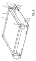
- Fig. 1 shows an exemplary embodiment of a connection box according to the invention.
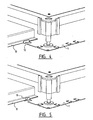
- the connection box comprises a base 1, a frame 4 which can be mounted thereon and a cover 5 which can be fixed on this frame 4. Between frame 4 and base 1 are provided adjusting means for setting the height H (see fig. 2) of frame 4 relative to base 1.
- the adjusting means consist of four sets of three elements 2, 7, 8 which are directed perpendicularly of base 1 and co-act telescopically in pairwise manner, and which are arranged at the corner points of frame 4.
- the first element is a screw 2 which is connected non-rotatably to base 1.
- This non-rotating connection is here obtained by using a screw having a head with slot, and by providing base plate 1 with a part 9 protruding from the base and having a form complementary to the slot.
- fig. 3 which shows the underside of base plate 1, this part protruding from the base is designated with reference numeral 9.
- the head of screw 2 is received in a clinch ring 3 fixed on the base in order to obtain a limited possible movement of screw 2 in a plane parallel to the base.
- the second element of the three telescopically co-acting elements is adjusting bush 7, and the third element is threaded bore 8.
- the adjusting bush is of the M14/8 type and screw 2 is of the PV M8x50 type, and threaded bore 8 is adapted to adjusting bush 7.
- screw 2 here has a right-hand thread, while threaded bore 8 uses a left-hand thread such that raising the adjusting bush likewise results in a raising of the frame relative to the adjusting bush.
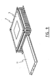
- Base plate 1 is further provided on each of its four side edges with thee pairs of lips 10, 10', wherein the lips of each pair are situated at a distance from each other substantially corresponding to the width of a determined type of floor channel.
- a floor channel can be positioned between one pair of lips 10, 10'.
- the lips can then be folded against the channel to clamp the channel fixedly against base 1 of the connection box. In this manner a good electrical contact is obtained between floor channel 11 and base 1 on the one hand, and it is ensured on the other that floor channel 11 is connected in substantially immobile manner to base 1.
- Floor channel 11 does not therefore have to be welded to base 1.
- frame 4 can be provided at different positions with grooves, whereby the connection box can be positioned and aligned in simple manner during installation thereof.
- connection box After the installation of the floor channels and the connection boxes, the connection box must be provided with side walls. These side walls can take on the form of a closing element according to the invention, as will be elucidated in detail hereinbelow.
- Fig. 6 shows a front view of an exemplary embodiment of the closing element according to the invention.
- the closing element is a plate-like element 12 which is provided with a number of bending lines 13 to 20 and a number of cutting lines 21 to 24, 21' to 24'.
- the bending lines 15 to 20 can for instance be used to adapt closing plate 12 to the height H at which the connection box is set.
- Cutting lines 22 to 24 and 22' to 24' can be used to adapt the closing element to the width of the floor channel.
- bending lines 13 to 20 can also be cut, but it is generally recommended to bend the part to be removed at a right angle, as will be set forth below with reference to fig. 7, 8 and 9.
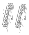
- the closing element is adapted to a floor channel with a width B1 and a set height corresponding to bending line 18.
- a number of parts below bending line 18 can be cut away, and cutting lines 24 and 24' can be cut up to bending line 15.
- the closing elements can be slotted into the grooves on the side of the connection box after the floor box has been set to the correct height. These closing elements can then be mutually connected and fixed. This can for instance take place by bending side flanges 31, 32 (see fig. 6), or using for instance a cable cord through holes 33-36 in side flanges 31, 32, or with adhesive tape, a steel binding wire, etc.
- connection box In order to elucidate the advantages of the invention still further, the assembly of a connection box according to the invention is briefly described below.
- connection box can be provided on the top with a centre marking on each side. After alignment the box can be fixed to a concrete construction floor using for instance four drive plugs.
- connection boxes When the first connection box is mounted, the laying and mounting of the floor channels made to size can begin. From this "fixed point" the channels and boxes are laid and mounted serially. The channels are clamped on the pre-cleaned base plate by bending down the already bent, upright lips. These clamping lips have two functions, i.e. to fix the floor channel on the connection box and to establish an electrical earth contact.
- the stated solution has the advantage that there is no necessity for a stop or fixed insertion depth of the channel relative to the floor box, thereby creating a freedom to absorb installation tolerances by means of a small variation in the insertion depth of the channel in the floor box.
- the connection boxes can now be set to the desired finishing floor height. Height-adjustment can take place using a special bit in combination with an electrical screwdriver which is set at a light position of a maximum of 5 Nm. A standard manual or machine screwdriver with a width of 13x2 mm is also possible.
- connection boxes After setting the height of the connection boxes, the nominal height is known or can be measured.
- the side walls (closing plates 12) can be adapted by means of cutting and bending. This assembly does not have to take place in situ, and can be prepared in a comfortable work posture. Note that the diverse connection boxes can vary slightly in height. This can be compensated by the insertion tolerance present in insertion grooves 37 arranged in the frame. After adjustment, the side walls can be pushed into the grooves and mutually connected to form a strong whole. The side walls can optionally also be fixed and/or sealed with adhesive tape.
- the finishing floor can now be arranged and made level with the upper side of the box edge. No parts protrude above this edge, so that the floor can be levelled neatly.
Landscapes
- Engineering & Computer Science (AREA)
- Architecture (AREA)
- Civil Engineering (AREA)
- Structural Engineering (AREA)
- Connection Or Junction Boxes (AREA)
- Connector Housings Or Holding Contact Members (AREA)
- Patch Boards (AREA)
Applications Claiming Priority (2)
| Application Number | Priority Date | Filing Date | Title |
|---|---|---|---|
| NL1025967 | 2004-04-16 | ||
| NL1025967A NL1025967C2 (nl) | 2004-04-16 | 2004-04-16 | Aansluitdoos en afsluitelement voor een aansluitdoos. |
Publications (2)
| Publication Number | Publication Date |
|---|---|
| EP1592103A2 true EP1592103A2 (de) | 2005-11-02 |
| EP1592103A3 EP1592103A3 (de) | 2011-01-19 |
Family
ID=34938192
Family Applications (1)
| Application Number | Title | Priority Date | Filing Date |
|---|---|---|---|
| EP05075925A Withdrawn EP1592103A3 (de) | 2004-04-16 | 2005-04-18 | Anschlussdose und Abdeckelement dafür. |
Country Status (2)
| Country | Link |
|---|---|
| EP (1) | EP1592103A3 (de) |
| NL (1) | NL1025967C2 (de) |
Cited By (1)
| Publication number | Priority date | Publication date | Assignee | Title |
|---|---|---|---|---|
| EP2924831A1 (de) | 2014-03-27 | 2015-09-30 | Vergokan | Einstellbare Bodenkassette für Bodengepäckraumsysteme |
Family Cites Families (3)
| Publication number | Priority date | Publication date | Assignee | Title |
|---|---|---|---|---|
| DE6906706U (de) * | 1969-02-20 | 1969-06-19 | Siemens Ag | Bodendose fuer elektrische unterflur-installationen |
| DE4234751C2 (de) * | 1992-10-15 | 1997-02-06 | Bettermann Obo Ohg | Unterfluranschlußdose |
| SE520905C2 (sv) * | 2002-06-11 | 2003-09-09 | Thorsman & Co Ab | Ingjutningslåda för elektriska golvinstallationer |
-
2004
- 2004-04-16 NL NL1025967A patent/NL1025967C2/nl not_active IP Right Cessation
-
2005
- 2005-04-18 EP EP05075925A patent/EP1592103A3/de not_active Withdrawn
Cited By (2)
| Publication number | Priority date | Publication date | Assignee | Title |
|---|---|---|---|---|
| EP2924831A1 (de) | 2014-03-27 | 2015-09-30 | Vergokan | Einstellbare Bodenkassette für Bodengepäckraumsysteme |
| RU2673796C2 (ru) * | 2014-03-27 | 2018-11-30 | Вергокан | Регулируемая напольная распределительная коробка для систем напольного желоба для кабелей |
Also Published As
| Publication number | Publication date |
|---|---|
| EP1592103A3 (de) | 2011-01-19 |
| NL1025967C2 (nl) | 2005-10-18 |
Similar Documents
| Publication | Publication Date | Title |
|---|---|---|
| CA2843975C (en) | Electrical box extension assembly | |
| DE60108569T2 (de) | Einstellbarer Eckverbinder | |
| US20080156513A1 (en) | Electrical box mounting plate with adjustable ring | |
| US20180048134A1 (en) | Mounting bracket with far side support | |
| US10434672B2 (en) | Cutting tool | |
| EP0559085A1 (de) | Boden- oder Terrassenablauf | |
| US8044300B1 (en) | Two-gang low voltage mounting bracket with front plate and retractable clamp arms for rapid mounting using hole saw | |
| EP1592103A2 (de) | Anschlussdose und Abdeckelement dafür. | |
| US5491901A (en) | Mechanical depthsetting device | |
| CN104074288A (zh) | 幕墙多自由度支撑体系 | |
| EP2590280B1 (de) | Bodenkanalsystem zur Leitungsführung und zum Geräteeinbau | |
| KR101483500B1 (ko) | 타일 커팅기 | |
| DE4012442C2 (de) | ||
| EP1102375B1 (de) | Leitungsführungskanal | |
| CN111637339B (zh) | 一种多功能建筑工程预算演练设备 | |
| DE102010022579B4 (de) | Gehrungslehre | |
| CN221850308U (zh) | 多功能线槽裁剪辅助器 | |
| JP2024052301A (ja) | ケラバ包み用下地金具 | |
| CN222352432U (zh) | 一种空调外机地架 | |
| CN221328849U (zh) | 一种屋顶光伏装配挂钩 | |
| CN103924910A (zh) | 分隔壁 | |
| EP4148338B1 (de) | Kombination aus klammer und profilträger | |
| CA2540905C (en) | Universal staircase tool | |
| CN222833246U (zh) | 容器组件、容器及刚性平台 | |
| US20030235323A1 (en) | Pre-embedded in-wall speaker seat |
Legal Events
| Date | Code | Title | Description |
|---|---|---|---|
| PUAI | Public reference made under article 153(3) epc to a published international application that has entered the european phase |
Free format text: ORIGINAL CODE: 0009012 |
|
| AK | Designated contracting states |
Kind code of ref document: A2 Designated state(s): AT BE BG CH CY CZ DE DK EE ES FI FR GB GR HU IE IS IT LI LT LU MC NL PL PT RO SE SI SK TR |
|
| AX | Request for extension of the european patent |
Extension state: AL BA HR LV MK YU |
|
| RAP1 | Party data changed (applicant data changed or rights of an application transferred) |
Owner name: VAN GEEL LEGRAND B.V. |
|
| PUAL | Search report despatched |
Free format text: ORIGINAL CODE: 0009013 |
|
| AK | Designated contracting states |
Kind code of ref document: A3 Designated state(s): AT BE BG CH CY CZ DE DK EE ES FI FR GB GR HU IE IS IT LI LT LU MC NL PL PT RO SE SI SK TR |
|
| AX | Request for extension of the european patent |
Extension state: AL BA HR LV MK YU |
|
| 17P | Request for examination filed |
Effective date: 20110620 |
|
| AKX | Designation fees paid |
Designated state(s): AT BE BG CH CY CZ DE DK EE ES FI FR GB GR HU IE IS IT LI LT LU MC NL PL PT RO SE SI SK TR |
|
| STAA | Information on the status of an ep patent application or granted ep patent |
Free format text: STATUS: THE APPLICATION IS DEEMED TO BE WITHDRAWN |
|
| 18D | Application deemed to be withdrawn |
Effective date: 20141101 |