EP1591990A1 - Display device drive apparatus and drive method - Google Patents
Display device drive apparatus and drive method Download PDFInfo
- Publication number
- EP1591990A1 EP1591990A1 EP05009089A EP05009089A EP1591990A1 EP 1591990 A1 EP1591990 A1 EP 1591990A1 EP 05009089 A EP05009089 A EP 05009089A EP 05009089 A EP05009089 A EP 05009089A EP 1591990 A1 EP1591990 A1 EP 1591990A1
- Authority
- EP
- European Patent Office
- Prior art keywords
- display
- brightness
- screen
- area
- driving
- Prior art date
- Legal status (The legal status is an assumption and is not a legal conclusion. Google has not performed a legal analysis and makes no representation as to the accuracy of the status listed.)
- Granted
Links
Images



Classifications
-
- G—PHYSICS
- G09—EDUCATION; CRYPTOGRAPHY; DISPLAY; ADVERTISING; SEALS
- G09G—ARRANGEMENTS OR CIRCUITS FOR CONTROL OF INDICATING DEVICES USING STATIC MEANS TO PRESENT VARIABLE INFORMATION
- G09G3/00—Control arrangements or circuits, of interest only in connection with visual indicators other than cathode-ray tubes
- G09G3/20—Control arrangements or circuits, of interest only in connection with visual indicators other than cathode-ray tubes for presentation of an assembly of a number of characters, e.g. a page, by composing the assembly by combination of individual elements arranged in a matrix no fixed position being assigned to or needed to be assigned to the individual characters or partial characters
- G09G3/2007—Display of intermediate tones
-
- G—PHYSICS
- G09—EDUCATION; CRYPTOGRAPHY; DISPLAY; ADVERTISING; SEALS
- G09G—ARRANGEMENTS OR CIRCUITS FOR CONTROL OF INDICATING DEVICES USING STATIC MEANS TO PRESENT VARIABLE INFORMATION
- G09G3/00—Control arrangements or circuits, of interest only in connection with visual indicators other than cathode-ray tubes
- G09G3/20—Control arrangements or circuits, of interest only in connection with visual indicators other than cathode-ray tubes for presentation of an assembly of a number of characters, e.g. a page, by composing the assembly by combination of individual elements arranged in a matrix no fixed position being assigned to or needed to be assigned to the individual characters or partial characters
- G09G3/22—Control arrangements or circuits, of interest only in connection with visual indicators other than cathode-ray tubes for presentation of an assembly of a number of characters, e.g. a page, by composing the assembly by combination of individual elements arranged in a matrix no fixed position being assigned to or needed to be assigned to the individual characters or partial characters using controlled light sources
- G09G3/28—Control arrangements or circuits, of interest only in connection with visual indicators other than cathode-ray tubes for presentation of an assembly of a number of characters, e.g. a page, by composing the assembly by combination of individual elements arranged in a matrix no fixed position being assigned to or needed to be assigned to the individual characters or partial characters using controlled light sources using luminous gas-discharge panels, e.g. plasma panels
- G09G3/288—Control arrangements or circuits, of interest only in connection with visual indicators other than cathode-ray tubes for presentation of an assembly of a number of characters, e.g. a page, by composing the assembly by combination of individual elements arranged in a matrix no fixed position being assigned to or needed to be assigned to the individual characters or partial characters using controlled light sources using luminous gas-discharge panels, e.g. plasma panels using AC panels
- G09G3/296—Driving circuits for producing the waveforms applied to the driving electrodes
-
- G—PHYSICS
- G09—EDUCATION; CRYPTOGRAPHY; DISPLAY; ADVERTISING; SEALS
- G09G—ARRANGEMENTS OR CIRCUITS FOR CONTROL OF INDICATING DEVICES USING STATIC MEANS TO PRESENT VARIABLE INFORMATION
- G09G3/00—Control arrangements or circuits, of interest only in connection with visual indicators other than cathode-ray tubes
- G09G3/20—Control arrangements or circuits, of interest only in connection with visual indicators other than cathode-ray tubes for presentation of an assembly of a number of characters, e.g. a page, by composing the assembly by combination of individual elements arranged in a matrix no fixed position being assigned to or needed to be assigned to the individual characters or partial characters
- G09G3/22—Control arrangements or circuits, of interest only in connection with visual indicators other than cathode-ray tubes for presentation of an assembly of a number of characters, e.g. a page, by composing the assembly by combination of individual elements arranged in a matrix no fixed position being assigned to or needed to be assigned to the individual characters or partial characters using controlled light sources
- G09G3/30—Control arrangements or circuits, of interest only in connection with visual indicators other than cathode-ray tubes for presentation of an assembly of a number of characters, e.g. a page, by composing the assembly by combination of individual elements arranged in a matrix no fixed position being assigned to or needed to be assigned to the individual characters or partial characters using controlled light sources using electroluminescent panels
-
- G—PHYSICS
- G09—EDUCATION; CRYPTOGRAPHY; DISPLAY; ADVERTISING; SEALS
- G09G—ARRANGEMENTS OR CIRCUITS FOR CONTROL OF INDICATING DEVICES USING STATIC MEANS TO PRESENT VARIABLE INFORMATION
- G09G3/00—Control arrangements or circuits, of interest only in connection with visual indicators other than cathode-ray tubes
- G09G3/20—Control arrangements or circuits, of interest only in connection with visual indicators other than cathode-ray tubes for presentation of an assembly of a number of characters, e.g. a page, by composing the assembly by combination of individual elements arranged in a matrix no fixed position being assigned to or needed to be assigned to the individual characters or partial characters
- G09G3/34—Control arrangements or circuits, of interest only in connection with visual indicators other than cathode-ray tubes for presentation of an assembly of a number of characters, e.g. a page, by composing the assembly by combination of individual elements arranged in a matrix no fixed position being assigned to or needed to be assigned to the individual characters or partial characters by control of light from an independent source
- G09G3/36—Control arrangements or circuits, of interest only in connection with visual indicators other than cathode-ray tubes for presentation of an assembly of a number of characters, e.g. a page, by composing the assembly by combination of individual elements arranged in a matrix no fixed position being assigned to or needed to be assigned to the individual characters or partial characters by control of light from an independent source using liquid crystals
-
- H—ELECTRICITY
- H04—ELECTRIC COMMUNICATION TECHNIQUE
- H04N—PICTORIAL COMMUNICATION, e.g. TELEVISION
- H04N21/00—Selective content distribution, e.g. interactive television or video on demand [VOD]
- H04N21/40—Client devices specifically adapted for the reception of or interaction with content, e.g. set-top-box [STB]; Operations thereof
- H04N21/43—Processing of content or additional data, e.g. demultiplexing additional data from a digital video stream; Elementary client operations, e.g. monitoring of home network or synchronising decoder's clock; Client middleware
- H04N21/431—Generation of visual interfaces for content selection or interaction; Content or additional data rendering
- H04N21/4318—Generation of visual interfaces for content selection or interaction; Content or additional data rendering by altering the content in the rendering process, e.g. blanking, blurring or masking an image region
-
- H—ELECTRICITY
- H04—ELECTRIC COMMUNICATION TECHNIQUE
- H04N—PICTORIAL COMMUNICATION, e.g. TELEVISION
- H04N5/00—Details of television systems
- H04N5/44—Receiver circuitry for the reception of television signals according to analogue transmission standards
- H04N5/57—Control of contrast or brightness
-
- G—PHYSICS
- G09—EDUCATION; CRYPTOGRAPHY; DISPLAY; ADVERTISING; SEALS
- G09G—ARRANGEMENTS OR CIRCUITS FOR CONTROL OF INDICATING DEVICES USING STATIC MEANS TO PRESENT VARIABLE INFORMATION
- G09G2320/00—Control of display operating conditions
- G09G2320/02—Improving the quality of display appearance
- G09G2320/0271—Adjustment of the gradation levels within the range of the gradation scale, e.g. by redistribution or clipping
-
- G—PHYSICS
- G09—EDUCATION; CRYPTOGRAPHY; DISPLAY; ADVERTISING; SEALS
- G09G—ARRANGEMENTS OR CIRCUITS FOR CONTROL OF INDICATING DEVICES USING STATIC MEANS TO PRESENT VARIABLE INFORMATION
- G09G2320/00—Control of display operating conditions
- G09G2320/06—Adjustment of display parameters
- G09G2320/0626—Adjustment of display parameters for control of overall brightness
-
- G—PHYSICS
- G09—EDUCATION; CRYPTOGRAPHY; DISPLAY; ADVERTISING; SEALS
- G09G—ARRANGEMENTS OR CIRCUITS FOR CONTROL OF INDICATING DEVICES USING STATIC MEANS TO PRESENT VARIABLE INFORMATION
- G09G2320/00—Control of display operating conditions
- G09G2320/06—Adjustment of display parameters
- G09G2320/066—Adjustment of display parameters for control of contrast
-
- G—PHYSICS
- G09—EDUCATION; CRYPTOGRAPHY; DISPLAY; ADVERTISING; SEALS
- G09G—ARRANGEMENTS OR CIRCUITS FOR CONTROL OF INDICATING DEVICES USING STATIC MEANS TO PRESENT VARIABLE INFORMATION
- G09G2320/00—Control of display operating conditions
- G09G2320/06—Adjustment of display parameters
- G09G2320/0686—Adjustment of display parameters with two or more screen areas displaying information with different brightness or colours
-
- G—PHYSICS
- G09—EDUCATION; CRYPTOGRAPHY; DISPLAY; ADVERTISING; SEALS
- G09G—ARRANGEMENTS OR CIRCUITS FOR CONTROL OF INDICATING DEVICES USING STATIC MEANS TO PRESENT VARIABLE INFORMATION
- G09G2330/00—Aspects of power supply; Aspects of display protection and defect management
- G09G2330/02—Details of power systems and of start or stop of display operation
- G09G2330/021—Power management, e.g. power saving
-
- G—PHYSICS
- G09—EDUCATION; CRYPTOGRAPHY; DISPLAY; ADVERTISING; SEALS
- G09G—ARRANGEMENTS OR CIRCUITS FOR CONTROL OF INDICATING DEVICES USING STATIC MEANS TO PRESENT VARIABLE INFORMATION
- G09G2360/00—Aspects of the architecture of display systems
- G09G2360/16—Calculation or use of calculated indices related to luminance levels in display data
-
- G—PHYSICS
- G09—EDUCATION; CRYPTOGRAPHY; DISPLAY; ADVERTISING; SEALS
- G09G—ARRANGEMENTS OR CIRCUITS FOR CONTROL OF INDICATING DEVICES USING STATIC MEANS TO PRESENT VARIABLE INFORMATION
- G09G3/00—Control arrangements or circuits, of interest only in connection with visual indicators other than cathode-ray tubes
- G09G3/20—Control arrangements or circuits, of interest only in connection with visual indicators other than cathode-ray tubes for presentation of an assembly of a number of characters, e.g. a page, by composing the assembly by combination of individual elements arranged in a matrix no fixed position being assigned to or needed to be assigned to the individual characters or partial characters
-
- G—PHYSICS
- G09—EDUCATION; CRYPTOGRAPHY; DISPLAY; ADVERTISING; SEALS
- G09G—ARRANGEMENTS OR CIRCUITS FOR CONTROL OF INDICATING DEVICES USING STATIC MEANS TO PRESENT VARIABLE INFORMATION
- G09G3/00—Control arrangements or circuits, of interest only in connection with visual indicators other than cathode-ray tubes
- G09G3/20—Control arrangements or circuits, of interest only in connection with visual indicators other than cathode-ray tubes for presentation of an assembly of a number of characters, e.g. a page, by composing the assembly by combination of individual elements arranged in a matrix no fixed position being assigned to or needed to be assigned to the individual characters or partial characters
- G09G3/22—Control arrangements or circuits, of interest only in connection with visual indicators other than cathode-ray tubes for presentation of an assembly of a number of characters, e.g. a page, by composing the assembly by combination of individual elements arranged in a matrix no fixed position being assigned to or needed to be assigned to the individual characters or partial characters using controlled light sources
- G09G3/28—Control arrangements or circuits, of interest only in connection with visual indicators other than cathode-ray tubes for presentation of an assembly of a number of characters, e.g. a page, by composing the assembly by combination of individual elements arranged in a matrix no fixed position being assigned to or needed to be assigned to the individual characters or partial characters using controlled light sources using luminous gas-discharge panels, e.g. plasma panels
Definitions
- the present invention relates to a drive apparatus of a display device and the drive method therefor.
- the brightness is corrected simply in accordance with the position of an area on the screen. Therefore, effects provided by the correction are plain and monotonous. Therefore, in some cases, there is little improvement in display quality depending upon a brightness distribution of a screen image, or the display quality improvement by the brightness correction is limited.
- the present invention is made to solve such problems, and provides a drive apparatus of the display device for making the brightness correction of the screen for raising the display quality in accordance with a brightness situation of the display screen image while restraining or decreasing the electric power consumption, and the drive method.
- the invention of claim 1 resides in a display-device drive apparatus for driving a display device in accordance with a video signal and displaying a screen image on the display screen of said display device, which includes a detecting section for detecting a brightness level of the screen image of said video signal as an area brightness level for each of a plurality of display areas on said display screen; and an adjustment driving section for comparing said area brightness levels with each other and driving said display device by a driving signal representing said screen image so as to form a brightness level distribution of said screen image according to adjustment characteristics determined in accordance with the difference between the area brightness levels.
- the invention of claim 8 resides in a display driving method in a display-device drive apparatus for driving a display device in accordance with a video signal and displaying a screen image on the display screen of said display device, the display driving method which includes a detecting step for detecting a brightness level of the screen image of said video signal as an area brightness level for each of a plurality of display areas on said display screen; and an adjustment driving step for comparing said area brightness levels with each other and driving said display device by a driving signal representing said screen image so as to form a brightness level distribution of said screen image according to adjustment characteristics determined in accordance with the difference between the area brightness levels.
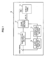
- Fig. 1 shows a drive apparatus of a display panel according to a first embodiment of the present invention.
- the display panel drive apparatus 10 may be, for example, a digital broadcast receiver of a wall hanging type, and may be also a thin-panel display device provided in an audio visual system. Otherwise, the display panel drive apparatus 10 may be also a display device provided in an in-car equipment such as a car navigation device, etc.
- a gain varying section 11 is a circuit for making a brightness correction of the video signal by multiplying a predetermined gain on the basis of commands from a correction characteristic control section 15 described later. Such correction processing can be performed by setting a different correction value of the gain for each area of a display screen.
- a panel driving section 12 includes a circuit for generating pixel data for display in a display panel 13 from the video signal corrected in brightness in the gain varying section 11, and also includes a circuit such as a frame memory, etc. for once accumulating such pixel data over one to several frames.
- the panel driving section 12 also generates a driving pulse as a driving signal synchronized with a synchronous signal included in the video signal and operating each pixel of the display panel 13 in accordance with the pixel data. Accordingly, various kinds of driver circuits for operating each electrode included in the display panel 13 by these driving pulses, and a control circuit of such drivers are also included in the panel driving section 12.
- the display panel 13 is a thin-panel display such as a PDP, and has row electrodes X1 to Xn and row electrodes Y1 to Yn constituting row electrode pairs corresponding to respective rows (first to n-th rows) on the screen in one pair of an X-electrode and a Y-electrode . Further, the display panel 13 is provided with column electrodes D1 to Dm corresponding to respective columns (first to m-th columns) on the screen and perpendicular to the above row electrode pairs, and unillustrated dielectric layers and discharge spatial layers are provided therebetween.
- One display cell C(i, j) is formed in a intersecting portion of one pair of row electrodes (Xi, Yi) and one column electrode Dj.
- Each electrode of the display panel 13 is connected to various kinds of driver circuits of the panel driving section 12, and is operated by the driving pulses supplied from the driver circuits.
- the detailed configuration of the display panel 13 is similar to that of the display panel shown, for example, in the above patent document 1.
- a block brightness detecting section 14 (hereinafter, simply referred to as a "detecting section 14") is a section for detecting brightness information in each area of the display screen.
- Various parameters can be used as such brightness information.
- APL Average Pulse Level
- APL Average Pulse Level representing an average brightness level of the video signal within a unit display period is used.
- a correction characteristic control section 15 (hereinafter, simply referred to as a "control section 15") is a section for controlling correction characteristics with respect to the brightness of the input video signal on the basis of a detection result of the detecting section 14.
- the brightness gain in the gain varying section 11 may be adjusted, or a pulse rate of the driving pulse in the panel driving section 12 may be adjusted.
- the detecting section 14 detects APL representing the brightness information with respect to each area obtained by dividing the screen into a plurality of areas.
- APL representing the brightness information with respect to each area obtained by dividing the screen into a plurality of areas.
- one screen is divided into five areas, for example, with respect to each of the horizontal and vertical directions as shown in Fig. 2, hence the screen is divided into 25 areas.
- the brightness information for five portions (hereinafter, also referred to as "blocks") constructed by the blocks at four corners and the center of the screen.
- the detecting section 14 detects the brightnesses of the blocks at left, right, upper and lower corners of the screen as APLUL, APLUR, APLLL and APLLR.
- the calculating method of APL LOCAL is not limited to such a technique. For example, all the APLs in each block of a screen outer circumferential edge are added together and may be divided by a block number of the outer circumferential edge. Otherwise, the APLs of respective central portion blocks of the screen four corners and the screen outer circumference are added together and may be divided into eight portions and APL LOCAL may be calculated.
- the detecting section 14 detects the brightness in the block of the screen center as a central portion brightness APL CENTER .
- APL CENTER may be also calculated by including APLs of a plurality of blocks surrounding the block of the screen central portion instead of simple use of only one block of the central portion.
- the control section 15 performs the following control of the correction characteristics of a brightness gain on the basis of the detecting result of the brightness information using the detecting section 14.
- the control section 15 sends to the gain varying section 11 commands for executing the correction characteristics of the brightness gain set in advance in the gain varying section 11.
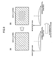
- the brightness gain correction in the gain varying section 11 in this case will be schematically described in Fig. 3.
- the brightness correction characteristic of a so-called "circumferential portion brightness drop" as shown as shown in the lower portions of (a) and (b) of Fig. 3 is set as a reference correction characteristic in advance in the gain varying section 11.
- the correction using the "circumferential portion brightness drop" is a correction in which the brightness gain of the circumferential portion of the screen is set to be lower than that of the central portion of the screen.
- Ahighbrightness feeling can be added by making such a correction with respect to the display screen image on the screen while restraining electric power consumption by utilizing a visual tendency of a human in which the human is likely to notice the screen central portion in comparison with the screen circumferential portion.
- the brightness gain correction shown in Fig. 3 illustrates only in the horizontal direction of the screen, but a correction characteristic having a similar tendency is also set with respect to the vertical direction.
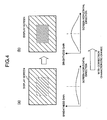
- control section 15 sends commands to the gain varying section 11 for changing the reference correction characteristics set in the gain varying section 11. A correction of the brightness gain in this case will be described based on Figs. 4 and 5.
- the control section 15 when the brightness of the central portion of the screen is a large value exceeding the predetermined threshold value in comparison with the brightness of the circumferential portion, the control section 15 further increases the brightness gain deviation of the reference correction characteristics under the screen in (b) of Fig. 4, and sends commands for control for providing the correction characteristics as shown in the lower part of (b) of Fig. 4 to the gain varying section 11.
- the brightness of the screen central portion is further emphasized and the brightness distribution of the screen as shown in (b) of Fig. 4 is attained.
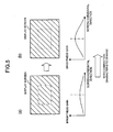
- the correction characteristic is also similarly changed with respect to a case in which the brightness of the central portion of the screen is smaller than a predetermined threshold value in comparison with the brightness of the circumferential portion.
- the brightness of the central portion of the screen is increased in comparison with that before the correction, and a high brightness feeling as the entire screen is obtained.
- the screen brightness correction is performed by correcting the brightness gain in the gain varying section 11 as an example.
- the control section 15 may alsomake the brightness correction by controlling a mode of the driving pulse for the panel driving section 12.
- the control section 15 may also make the brightness correction on the screen by giving control commands for adjusting a parameter with respect to the driving signal such as a repeating frequency, a pulse width, etc. of a discharge maintaining pulse to the panel driving section 12.
- different correction characteristics are set with respect to each of the horizontal and vertical directions of the screen, and the correction characteristics may be also independently changed in accordance with the brightness difference between blocks in each of the horizontal and vertical directions. Further, the correction characteristics may be also set with an arbitrary area of the screen as a reference instead of the correction characteristics of the brightness with the central portion of the display screen as a reference. In the above description, the correction characteristics are shown by a waveform continuously changed in the horizontal to vertical directions. However, for example, as shown in Fig. 7, correction characteristics having a brightness gain stepwise changed every each block in the horizontal to vertical directions may be also set.
- the correction using the normal circumferential brightness drop is made.
- the correction for emphasizing the brightness of the screen central portion is made. Therefore, a high brightness feeling can be given to a user while restraining electric power consumption.
- the correction characteristics are changed in accordance with the brightness difference between respective blocks on the screen similarly to the first embodiment.
- the correction characteristics of the circumferential brightness drop are not adjusted as in the first embodiment, but the feature of the embodiment is in that the display quality of a screen image is improved while restraining electric power consumption by emphasizing the contrast of each area.
- the detecting section 14 detects brightness information on the screen, and detects the brightness APL LOCAL of a circumferential portion and the brightness APL CENTER of a central portion.
- the calculating method of APL LOCAL and APL CENTER is set similarly to that in the first embodiment.
- the control section 15 gives commands for control for making a correction for increasing the brightness gain of the screen central portion and reducing the brightness gain of the screen circumferential portion to the gain varying section 11.
- An image of the correction characteristics at this time is shown under the screen in (a) of Fig. 8.
- the brightness distribution of the screen after the correction attains the state shown in (b) of Fig. 8 by such a correction, and the contrast between the brightness of the screen central portion and the brightness of the circumferential portion is further clarified.
- the control section 15 sends commands for control for making a correction for reducing the brightness gain of the screen central portion and increasing the brightness gain of the screen circumferential portion to the gain varying section 11.
- the correction characteristics at this time is schematically shown in (b) of Fig. 9.
- the brightness distribution of the screen after the correction attains the state shown in (b) of Fig. 9 by such a correction, and the contrast between the brightness of the central portion of the screen and the brightness of the circumferential portion is further clarified.
- the brightness gain correction shown in Figs. 8 and 9 is shown only in the horizontal direction of the screen, but a correction characteristic having a similar tendency is also set in the vertical direction of the screen.
- the brightness difference between the central portion and the circumferential portion of the screen is further emphasized by making such a correction, and the contrast of the display image is strengthened. Therefore, a high brightness feeling can be given to a user while restraining electric power consumption.
- the screen brightness is controlled by adjusting the brightness gain in the gain varying section 11 as an example.
- the control section 15 may also control the brightness by giving commands for controlling the driving pulse with respect to the panel driving section 12.
- the control section 15 may also make the brightness correction on the screen by giving commands for control for adjusting a parameter with respect to the driving signal such as a repeating frequency, a pulse width, etc. of a discharge maintaining pulse to the panel driving section 12.
- correction characteristics are set with respect to each of the horizontal direction and the vertical direction of the screen, and the correction characteristics may be also independently changed in accordance with the brightness difference between blocks in each of the horizontal and vertical directions.
- the correction characteristics with an arbitrary area of the screen as a reference may be also set instead of the correction characteristics of the brightness with the central portion of the display screen as a reference.
- the correction characteristics are shown by a waveform continuously changed. However, for example, correction characteristics having a brightness gain stepwise changed every each block may be also set.
Landscapes
- Engineering & Computer Science (AREA)
- Physics & Mathematics (AREA)
- Theoretical Computer Science (AREA)
- Computer Hardware Design (AREA)
- General Physics & Mathematics (AREA)
- Signal Processing (AREA)
- Multimedia (AREA)
- Power Engineering (AREA)
- Plasma & Fusion (AREA)
- Chemical & Material Sciences (AREA)
- Crystallography & Structural Chemistry (AREA)
- Control Of Indicators Other Than Cathode Ray Tubes (AREA)
- Control Of Gas Discharge Display Tubes (AREA)
- Transforming Electric Information Into Light Information (AREA)
- Controls And Circuits For Display Device (AREA)
Abstract
Description
- The present invention relates to a drive apparatus of a display device and the drive method therefor.
- In recent years, for example, display devices using a flat-panel display of a light-emission type such as a plasma display panel (hereinafter, referred to as "PDP"), an electroluminescence panel, etc. as a display of a flat-panel type are widely made as products. In these display devices, for example, a technique as shown in Japanese Patent No. 3115727 (hereinafter, referred to as patent document 1) is disclosed as a display panel drive system for improving the quality of a screen image on the panel without increasing electric power consumption of the display device.
- In the prior art shown in the patent document, a configuration for increasing the brightness of a display area near the screen central portion of the display panel, and decreasing the brightness of the display area of a screen circumferential area is adopted. A high brightness feeling is obtained by adopting such a configuration with respect to the displayed screen image while restraining the electric power consumption utilizing the visual characteristics of a human tending to visually notice the central portion in comparison with the circumferential portion of the display screen.
- However, in such a prior art, the brightness is corrected simply in accordance with the position of an area on the screen. Therefore, effects provided by the correction are plain and monotonous. Therefore, in some cases, there is little improvement in display quality depending upon a brightness distribution of a screen image, or the display quality improvement by the brightness correction is limited.
- The present invention is made to solve such problems, and provides a drive apparatus of the display device for making the brightness correction of the screen for raising the display quality in accordance with a brightness situation of the display screen image while restraining or decreasing the electric power consumption, and the drive method.
- The invention of claim 1 resides in a display-device drive apparatus for driving a display device in accordance with a video signal and displaying a screen image on the display screen of said display device, which includes a detecting section for detecting a brightness level of the screen image of said video signal as an area brightness level for each of a plurality of display areas on said display screen; and an adjustment driving section for comparing said area brightness levels with each other and driving said display device by a driving signal representing said screen image so as to form a brightness level distribution of said screen image according to adjustment characteristics determined in accordance with the difference between the area brightness levels.
- The invention of claim 8 resides in a display driving method in a display-device drive apparatus for driving a display device in accordance with a video signal and displaying a screen image on the display screen of said display device, the display driving method which includes a detecting step for detecting a brightness level of the screen image of said video signal as an area brightness level for each of a plurality of display areas on said display screen; and an adjustment driving step for comparing said area brightness levels with each other and driving said display device by a driving signal representing said screen image so as to form a brightness level distribution of said screen image according to adjustment characteristics determined in accordance with the difference between the area brightness levels.
-
- Fig. 1 is a block diagram showing the configuration of a display panel drive apparatus according to a first embodiment of the present invention;
- Fig. 2 is an explanatory view showing one example of area division on the screen at a brightness information detecting time of each area of the display screen;
- Fig. 3 is a first explanatory view for illustrating a brightness correcting operation in the first embodiment of the present invention;
- Fig. 4 is a second explanatory view for illustrating the brightness correcting operation in the first embodiment of the present invention;
- Fig. 5 is a third explanatory view for illustrating the brightness correcting operation in the first embodiment of the present invention;
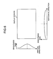
- Fig. 6 is an explanatory view showing a first application example in the first embodiment of the present invention;
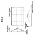
- Fig. 7 is an explanatory view showing a second application example in the first embodiment of the present invention;
- Fig. 8 is a first explanatory view for illustrating a brightness correcting operation in a second embodiment of the present invention; and
- Fig. 9 is a second explanatory view for illustrating the brightness correcting operation in the second embodiment of the present invention.
-
- Fig. 1 shows a drive apparatus of a display panel according to a first embodiment of the present invention.
- In Fig. 1, the display
panel drive apparatus 10 may be, for example, a digital broadcast receiver of a wall hanging type, and may be also a thin-panel display device provided in an audio visual system. Otherwise, the displaypanel drive apparatus 10 may be also a display device provided in an in-car equipment such as a car navigation device, etc. - With respect to an input video signal, a gain
varying section 11 is a circuit for making a brightness correction of the video signal by multiplying a predetermined gain on the basis of commands from a correctioncharacteristic control section 15 described later. Such correction processing can be performed by setting a different correction value of the gain for each area of a display screen. - A
panel driving section 12 includes a circuit for generating pixel data for display in adisplay panel 13 from the video signal corrected in brightness in the gainvarying section 11, and also includes a circuit such as a frame memory, etc. for once accumulating such pixel data over one to several frames. Thepanel driving section 12 also generates a driving pulse as a driving signal synchronized with a synchronous signal included in the video signal and operating each pixel of thedisplay panel 13 in accordance with the pixel data. Accordingly, various kinds of driver circuits for operating each electrode included in thedisplay panel 13 by these driving pulses, and a control circuit of such drivers are also included in thepanel driving section 12. - For example, the
display panel 13 is a thin-panel display such as a PDP, and has row electrodes X1 to Xn and row electrodes Y1 to Yn constituting row electrode pairs corresponding to respective rows (first to n-th rows) on the screen in one pair of an X-electrode and a Y-electrode . Further, thedisplay panel 13 is provided with column electrodes D1 to Dm corresponding to respective columns (first to m-th columns) on the screen and perpendicular to the above row electrode pairs, and unillustrated dielectric layers and discharge spatial layers are provided therebetween. One display cell C(i, j) is formed in a intersecting portion of one pair of row electrodes (Xi, Yi) and one column electrode Dj. Each electrode of thedisplay panel 13 is connected to various kinds of driver circuits of thepanel driving section 12, and is operated by the driving pulses supplied from the driver circuits. - The detailed configuration of the
display panel 13 is similar to that of the display panel shown, for example, in the above patent document 1. - On the other hand, a block brightness detecting section 14 (hereinafter, simply referred to as a "detecting
section 14") is a section for detecting brightness information in each area of the display screen. Various parameters can be used as such brightness information. However, in this embodiment, APL (Average Pulse Level) representing an average brightness level of the video signal within a unit display period is used. - A correction characteristic control section 15 (hereinafter, simply referred to as a "
control section 15") is a section for controlling correction characteristics with respect to the brightness of the input video signal on the basis of a detection result of thedetecting section 14. In the control of the correction characteristics, the brightness gain in the gainvarying section 11 may be adjusted, or a pulse rate of the driving pulse in thepanel driving section 12 may be adjusted. - Next, the operation of the display panel drive apparatus in the embodiment will be described.
- First, with respect to one screen of the input video signal, the detecting
section 14 detects APL representing the brightness information with respect to each area obtained by dividing the screen into a plurality of areas. When dividing the screen, one screen is divided into five areas, for example, with respect to each of the horizontal and vertical directions as shown in Fig. 2, hence the screen is divided into 25 areas. In this embodiment, the brightness information for five portions (hereinafter, also referred to as "blocks") constructed by the blocks at four corners and the center of the screen. - Namely, the detecting
section 14 detects the brightnesses of the blocks at left, right, upper and lower corners of the screen as APLUL, APLUR, APLLL and APLLR. The brightness APLLOCAL of a circumferential portion of the screen is calculated as - The calculating method of APLLOCAL is not limited to such a technique. For example, all the APLs in each block of a screen outer circumferential edge are added together and may be divided by a block number of the outer circumferential edge. Otherwise, the APLs of respective central portion blocks of the screen four corners and the screen outer circumference are added together and may be divided into eight portions and APLLOCAL may be calculated.
- Further, the detecting
section 14 detects the brightness in the block of the screen center as a central portion brightness APLCENTER. With respect to the detection of APLCENTER, APLCENTER may be also calculated by including APLs of a plurality of blocks surrounding the block of the screen central portion instead of simple use of only one block of the central portion. - The
control section 15 performs the following control of the correction characteristics of a brightness gain on the basis of the detecting result of the brightness information using thedetecting section 14. - First, when the difference between APLCENTER and APLLOCAL is equal to or less than a predetermined threshold value, the
control section 15 sends to the gainvarying section 11 commands for executing the correction characteristics of the brightness gain set in advance in the gainvarying section 11. The brightness gain correction in thegain varying section 11 in this case will be schematically described in Fig. 3. The brightness correction characteristic of a so-called "circumferential portion brightness drop" as shown as shown in the lower portions of (a) and (b) of Fig. 3 is set as a reference correction characteristic in advance in the gainvarying section 11. - The correction using the "circumferential portion brightness drop" is a correction in which the brightness gain of the circumferential portion of the screen is set to be lower than that of the central portion of the screen. Ahighbrightness feeling can be added by making such a correction with respect to the display screen image on the screen while restraining electric power consumption by utilizing a visual tendency of a human in which the human is likely to notice the screen central portion in comparison with the screen circumferential portion. The brightness gain correction shown in Fig. 3 illustrates only in the horizontal direction of the screen, but a correction characteristic having a similar tendency is also set with respect to the vertical direction.
- More specifically, as shown in (a) of Fig. 3, when the difference in brightness between the central portion and the circumferential portion in the brightness distribution over the screen is small, the correction of the "circumferential portion brightness drop" using the reference correction characteristics is made by the
gain varying section 11, and the brightness distribution of the screen after the correction has the shape shown in (b) of Fig. 3. In Fig. 3, the density of hatching on the screen schematically shows the brightness difference. - In contrast to this, when the difference between APLCENTER and APLLOCAL exceeds the predetermined threshold value, the
control section 15 sends commands to thegain varying section 11 for changing the reference correction characteristics set in thegain varying section 11. A correction of the brightness gain in this case will be described based on Figs. 4 and 5. - Namely, as shown in (a) of Fig. 4, when the brightness of the central portion of the screen is a large value exceeding the predetermined threshold value in comparison with the brightness of the circumferential portion, the
control section 15 further increases the brightness gain deviation of the reference correction characteristics under the screen in (b) of Fig. 4, and sends commands for control for providing the correction characteristics as shown in the lower part of (b) of Fig. 4 to thegain varying section 11. Thus, in the brightness distribution of the screen shown in (a) of Fig. 4, the brightness of the screen central portion is further emphasized and the brightness distribution of the screen as shown in (b) of Fig. 4 is attained. - On the contrary, as shown in (a) of Fig. 5, the correction characteristic is also similarly changed with respect to a case in which the brightness of the central portion of the screen is smaller than a predetermined threshold value in comparison with the brightness of the circumferential portion. Thus, as shown in (b) of Fig. 5, the brightness of the central portion of the screen is increased in comparison with that before the correction, and a high brightness feeling as the entire screen is obtained.
- In the above description, the screen brightness correction is performed by correcting the brightness gain in the
gain varying section 11 as an example. However, the present invention is not limited to such. For example, thecontrol section 15 may alsomake the brightness correction by controlling a mode of the driving pulse for thepanel driving section 12. Namely, thecontrol section 15 may also make the brightness correction on the screen by giving control commands for adjusting a parameter with respect to the driving signal such as a repeating frequency, a pulse width, etc. of a discharge maintaining pulse to thepanel driving section 12. - As shown in Fig. 6, different correction characteristics are set with respect to each of the horizontal and vertical directions of the screen, and the correction characteristics may be also independently changed in accordance with the brightness difference between blocks in each of the horizontal and vertical directions. Further, the correction characteristics may be also set with an arbitrary area of the screen as a reference instead of the correction characteristics of the brightness with the central portion of the display screen as a reference. In the above description, the correction characteristics are shown by a waveform continuously changed in the horizontal to vertical directions. However, for example, as shown in Fig. 7, correction characteristics having a brightness gain stepwise changed every each block in the horizontal to vertical directions may be also set.
- As described above, in accordance with the embodiment, when the brightness difference between the central portion and the circumferential portion of the screen is equal to or less than a predetermined threshold value in the display device having the correction characteristics of the circumferential brightness drop, the correction using the normal circumferential brightness drop is made. In contrast to this, when the brightness difference between the central portion and the circumferential portion exceeds the threshold value, the correction for emphasizing the brightness of the screen central portion is made. Therefore, a high brightness feeling can be given to a user while restraining electric power consumption.
- Next, a second embodiment of the present invention will be described. The configuration of a display panel drive apparatus in this embodiment is similar to that in the first embodiment and its description and explanation are therefore omitted.
- In this embodiment, the correction characteristics are changed in accordance with the brightness difference between respective blocks on the screen similarly to the first embodiment. However, the correction characteristics of the circumferential brightness drop are not adjusted as in the first embodiment, but the feature of the embodiment is in that the display quality of a screen image is improved while restraining electric power consumption by emphasizing the contrast of each area.
- The operation of the display panel drive apparatus in this embodiment will be described as follows.
- First, the detecting
section 14 detects brightness information on the screen, and detects the brightness APLLOCAL of a circumferential portion and the brightness APLCENTER of a central portion. The calculating method of APLLOCAL and APLCENTER is set similarly to that in the first embodiment. - When the brightness of the screen central portion is larger than that of the screen circumferential portion as shown in (a) of Fig. 8 in a detecting result in the detecting
section 14, i.e., when
APLCENTER > APLLOCAL,
thecontrol section 15 gives commands for control for making a correction for increasing the brightness gain of the screen central portion and reducing the brightness gain of the screen circumferential portion to thegain varying section 11. An image of the correction characteristics at this time is shown under the screen in (a) of Fig. 8. The brightness distribution of the screen after the correction attains the state shown in (b) of Fig. 8 by such a correction, and the contrast between the brightness of the screen central portion and the brightness of the circumferential portion is further clarified. - In contrast to this, when the brightness of the screen central portion is lower than the brightness of the screen circumferential portion as shown in (a) of Fig. 9 in the detecting result in the detecting
section 14, i.e.,
APLCENTER < APLLOCAL,
thecontrol section 15 sends commands for control for making a correction for reducing the brightness gain of the screen central portion and increasing the brightness gain of the screen circumferential portion to thegain varying section 11. The correction characteristics at this time is schematically shown in (b) of Fig. 9. The brightness distribution of the screen after the correction attains the state shown in (b) of Fig. 9 by such a correction, and the contrast between the brightness of the central portion of the screen and the brightness of the circumferential portion is further clarified. - The brightness gain correction shown in Figs. 8 and 9 is shown only in the horizontal direction of the screen, but a correction characteristic having a similar tendency is also set in the vertical direction of the screen.
- In this embodiment, the brightness difference between the central portion and the circumferential portion of the screen is further emphasized by making such a correction, and the contrast of the display image is strengthened. Therefore, a high brightness feeling can be given to a user while restraining electric power consumption.
- In the above explanation, the screen brightness is controlled by adjusting the brightness gain in the
gain varying section 11 as an example. However, the present invention is not limited to such an example. For example, thecontrol section 15 may also control the brightness by giving commands for controlling the driving pulse with respect to thepanel driving section 12. Namely, thecontrol section 15 may also make the brightness correction on the screen by giving commands for control for adjusting a parameter with respect to the driving signal such as a repeating frequency, a pulse width, etc. of a discharge maintaining pulse to thepanel driving section 12. - Further, different correction characteristics are set with respect to each of the horizontal direction and the vertical direction of the screen, and the correction characteristics may be also independently changed in accordance with the brightness difference between blocks in each of the horizontal and vertical directions. Further, the correction characteristics with an arbitrary area of the screen as a reference may be also set instead of the correction characteristics of the brightness with the central portion of the display screen as a reference. Further, in the above explanation, the correction characteristics are shown by a waveform continuously changed. However, for example, correction characteristics having a brightness gain stepwise changed every each block may be also set.
- The invention has been described with reference to the preferred embodiments thereof. It should be understood by those skilled in the art that a variety of alterations and modifications may be made from the embodiments described above. It is therefore contemplated that the appended claims encompass all such alterations and modifications.
Claims (8)
- A display-device drive apparatus for driving a display device in accordance with a video signal and displaying a screen image on the display screen of said display device, and including:a detecting section for detecting a brightness level of the screen image of said video signal as an area brightness level for each of a plurality of display areas on said display screen; andan adjustment driving section for comparing said area brightness levels with each other and driving said display device by a driving signal representing said screen image so as to form a brightness level distribution of said screen image according to adjustment characteristics determined in accordance with the difference between the area brightness levels.
- The display-device drive apparatus according to claim 1, wherein said plurality of display areas include a central area of said display screen and a circumferential area with respect to said central area.
- The display-device drive apparatus according to claim 2, wherein said adjustment driving section adjusts said screen image by the adjustment characteristics maintained to basic characteristics set in advance as long as the level difference is less than a predetermined threshold value.
- The display-device drive apparatus according to claim 2 , wherein said adjustment driving section sets said adjustment characteristics to enhancing characteristics when the level difference is equal to or more than a predetermined threshold value.
- The display-device drive apparatus according to claim 3, wherein said basic characteristics are characteristics for setting the brightness of said circumferential area to be lower than the brightness of said central area.
- The display-device drive apparatus according to claim 1, wherein, when the area brightness level in one area among said plurality of display areas is higher than the area brightness levels of other areas except for said one area, said adjustment driving section adjusts said video signal by the adjustment characteristics for setting the brightness of said one area to be higher than the brightnesses of said other areas.
- The display-device drive apparatus according to claim 1, wherein said detecting section detects an APL value every said plurality of display areas as said area brightness level.
- A display driving method in a display-device drive apparatus for driving a display device in accordance with a video signal and displaying a screen image on the display screen of said display device, the display driving method including:a detecting step for detecting a brightness level of the screen image of said video signal as an area brightness level for each of a plurality of display areas on said display screen; andan adjustment driving step for comparing said area brightness levels with each other and driving said display device by a driving signal representing said screen image so as to form a brightness level distribution of said screen image according to adjustment characteristics determined in accordance with the difference between the area brightness levels.
Applications Claiming Priority (2)
| Application Number | Priority Date | Filing Date | Title |
|---|---|---|---|
| JP2004131152A JP2005315956A (en) | 2004-04-27 | 2004-04-27 | Display unit driving device and driving method therefor |
| JP2004131152 | 2004-04-27 |
Publications (2)
| Publication Number | Publication Date |
|---|---|
| EP1591990A1 true EP1591990A1 (en) | 2005-11-02 |
| EP1591990B1 EP1591990B1 (en) | 2012-09-12 |
Family
ID=34935733
Family Applications (1)
| Application Number | Title | Priority Date | Filing Date |
|---|---|---|---|
| EP05009089A Expired - Fee Related EP1591990B1 (en) | 2004-04-27 | 2005-04-26 | Display device drive apparatus and drive method |
Country Status (4)
| Country | Link |
|---|---|
| US (1) | US20050248594A1 (en) |
| EP (1) | EP1591990B1 (en) |
| JP (1) | JP2005315956A (en) |
| KR (1) | KR100708250B1 (en) |
Cited By (3)
| Publication number | Priority date | Publication date | Assignee | Title |
|---|---|---|---|---|
| EP1809032A4 (en) * | 2004-11-05 | 2010-01-27 | Panasonic Corp | VIDEO SIGNAL TRANSFORMATION DEVICE AND VIDEO DISPLAY DEVICE |
| US11735141B2 (en) | 2020-03-26 | 2023-08-22 | Samsung Display Co., Ltd. | Display device and method of driving the same |
| US11915668B2 (en) | 2019-12-27 | 2024-02-27 | Samsung Display Co., Ltd. | Display device having uniform luminance, and driving method thereof |
Families Citing this family (19)
| Publication number | Priority date | Publication date | Assignee | Title |
|---|---|---|---|---|
| KR100745982B1 (en) | 2006-06-19 | 2007-08-06 | 삼성전자주식회사 | Image processing apparatus and method for reducing power of self-luminous display |
| KR100803545B1 (en) * | 2006-07-20 | 2008-02-15 | 엘지전자 주식회사 | Driving device for plasma display panel, and driving method thereof |
| KR101323433B1 (en) * | 2006-12-20 | 2013-10-29 | 엘지디스플레이 주식회사 | Liquid crystal display and method of driving the same |
| KR101350410B1 (en) * | 2007-02-22 | 2014-01-23 | 엘지디스플레이 주식회사 | Circuit for Image compensation, LCD including the same and driving method thereof |
| KR100936862B1 (en) | 2007-12-31 | 2010-01-15 | 삼성에스디아이 주식회사 | Display gradation representation device and gradation representation method |
| JP4743234B2 (en) | 2008-07-02 | 2011-08-10 | ソニー株式会社 | Display device and display method |
| US8576260B2 (en) * | 2008-11-12 | 2013-11-05 | Panasonic Corporation | Plasma display device and plasma display panel driving method |
| KR101246413B1 (en) * | 2008-11-13 | 2013-03-22 | 파나소닉 주식회사 | Plasma display device and plasma display panel driving method |
| US8471786B2 (en) | 2008-11-13 | 2013-06-25 | Panasonic Corporation | Plasma display device and plasma display panel driving method |
| WO2010067412A1 (en) * | 2008-12-09 | 2010-06-17 | 日立プラズマディスプレイ株式会社 | Plasma display and its driving method |
| JP4982510B2 (en) * | 2009-01-23 | 2012-07-25 | 株式会社日立製作所 | Video display device |
| EP2544170A4 (en) * | 2010-03-05 | 2013-05-01 | Panasonic Corp | METHOD OF CONTROLLING PLASMA DISPLAY DEVICE, PLASMA DISPLAY DEVICE, AND PLASMA DISPLAY SYSTEM |
| JP5800946B2 (en) * | 2013-05-10 | 2015-10-28 | キヤノン株式会社 | Image display apparatus and control method thereof |
| JP6274771B2 (en) * | 2013-07-26 | 2018-02-07 | 株式会社ジャパンディスプレイ | Light emitting element display device |
| US10225031B2 (en) * | 2016-11-02 | 2019-03-05 | The Nielsen Company (US) | Methods and apparatus for increasing the robustness of media signatures |
| KR102423637B1 (en) | 2017-10-27 | 2022-07-22 | 삼성디스플레이 주식회사 | Display apparatus and method of driving the same |
| KR102408001B1 (en) * | 2020-07-28 | 2022-06-14 | 엘지전자 주식회사 | Orgarnic light- emitting diode display device and operating method thereof |
| CN113810673B (en) * | 2021-09-24 | 2023-05-30 | 当趣网络科技(杭州)有限公司 | Projector uniformity testing method and device and computer readable storage medium |
| WO2025248709A1 (en) * | 2024-05-30 | 2025-12-04 | Ntt株式会社 | Video presentation device, video presentation method, and program |
Citations (6)
| Publication number | Priority date | Publication date | Assignee | Title |
|---|---|---|---|---|
| JPH06282241A (en) | 1993-03-25 | 1994-10-07 | Pioneer Electron Corp | Drive device for plasma display panel |
| JPH07210109A (en) | 1994-01-25 | 1995-08-11 | Pioneer Electron Corp | Method of driving flat display device |
| EP0888004A2 (en) | 1997-06-27 | 1998-12-30 | Pioneer Electronic Corporation | Brightness controlling apparatus |
| JPH11219152A (en) | 1998-02-02 | 1999-08-10 | Mitsubishi Electric Corp | Plasma display panel temperature control method and plasma display device |
| US20010000217A1 (en) * | 1997-01-30 | 2001-04-12 | Mitsubishi Denki Kabushiki Kaisha | Display apparatus |
| EP1265213A2 (en) | 2001-06-08 | 2002-12-11 | Pioneer Corporation | Display apparatus and display method |
Family Cites Families (1)
| Publication number | Priority date | Publication date | Assignee | Title |
|---|---|---|---|---|
| EP1437705A1 (en) * | 2003-01-10 | 2004-07-14 | Deutsche Thomson-Brandt Gmbh | Method for optimizing brightness in a display device and apparatus for implementing the method |
-
2004
- 2004-04-27 JP JP2004131152A patent/JP2005315956A/en not_active Withdrawn
-
2005
- 2005-04-25 KR KR1020050034047A patent/KR100708250B1/en not_active Expired - Fee Related
- 2005-04-26 US US11/114,218 patent/US20050248594A1/en not_active Abandoned
- 2005-04-26 EP EP05009089A patent/EP1591990B1/en not_active Expired - Fee Related
Patent Citations (6)
| Publication number | Priority date | Publication date | Assignee | Title |
|---|---|---|---|---|
| JPH06282241A (en) | 1993-03-25 | 1994-10-07 | Pioneer Electron Corp | Drive device for plasma display panel |
| JPH07210109A (en) | 1994-01-25 | 1995-08-11 | Pioneer Electron Corp | Method of driving flat display device |
| US20010000217A1 (en) * | 1997-01-30 | 2001-04-12 | Mitsubishi Denki Kabushiki Kaisha | Display apparatus |
| EP0888004A2 (en) | 1997-06-27 | 1998-12-30 | Pioneer Electronic Corporation | Brightness controlling apparatus |
| JPH11219152A (en) | 1998-02-02 | 1999-08-10 | Mitsubishi Electric Corp | Plasma display panel temperature control method and plasma display device |
| EP1265213A2 (en) | 2001-06-08 | 2002-12-11 | Pioneer Corporation | Display apparatus and display method |
Non-Patent Citations (3)
| Title |
|---|
| PATENT ABSTRACTS OF JAPAN vol. 1995, no. 01 28 February 1995 (1995-02-28) * |
| PATENT ABSTRACTS OF JAPAN vol. 1995, no. 11 26 December 1995 (1995-12-26) * |
| PATENT ABSTRACTS OF JAPAN vol. 1999, no. 13 30 November 1999 (1999-11-30) * |
Cited By (5)
| Publication number | Priority date | Publication date | Assignee | Title |
|---|---|---|---|---|
| EP1809032A4 (en) * | 2004-11-05 | 2010-01-27 | Panasonic Corp | VIDEO SIGNAL TRANSFORMATION DEVICE AND VIDEO DISPLAY DEVICE |
| US7956927B2 (en) | 2004-11-05 | 2011-06-07 | Panasonic Corporation | Video signal converter and video display device |
| US11915668B2 (en) | 2019-12-27 | 2024-02-27 | Samsung Display Co., Ltd. | Display device having uniform luminance, and driving method thereof |
| EP3843069B1 (en) * | 2019-12-27 | 2025-10-29 | Samsung Display Co., Ltd. | Display device and driving method thereof |
| US11735141B2 (en) | 2020-03-26 | 2023-08-22 | Samsung Display Co., Ltd. | Display device and method of driving the same |
Also Published As
| Publication number | Publication date |
|---|---|
| KR20060045841A (en) | 2006-05-17 |
| EP1591990B1 (en) | 2012-09-12 |
| KR100708250B1 (en) | 2007-04-16 |
| US20050248594A1 (en) | 2005-11-10 |
| JP2005315956A (en) | 2005-11-10 |
Similar Documents
| Publication | Publication Date | Title |
|---|---|---|
| EP1591990A1 (en) | Display device drive apparatus and drive method | |
| JPH08286636A (en) | Luminance adjusting device in plasma display panel | |
| US7221335B2 (en) | Image display method and device for plasma display panel | |
| US20030179162A1 (en) | Display apparatus capable of maintaining high image quality without dependence on display load, and method for driving the same | |
| JP2009122675A (en) | Driving device for liquid crystal display device and driving method thereof | |
| JP2005321664A (en) | Video display device | |
| JP2006184843A (en) | Image display apparatus and its driving method | |
| CN106991959B (en) | Image processing method and device for L ED display screen | |
| JP2005107544A (en) | Image display method and apparatus for plasma display panel | |
| JPH0876716A (en) | Multiscan adaptation type plasma display device | |
| JP2006301622A (en) | Plasma display panel driving method | |
| US20040155891A1 (en) | Method and apparatus for displaying grayscale of plasma display panel | |
| US20090201285A1 (en) | Plasma display panel driving method and plasma display device | |
| US20100066721A1 (en) | Plasma display device and driving method thereof | |
| US6727913B2 (en) | Method and device for displaying images on a matrix display device | |
| JP2003345297A (en) | Plasma display device | |
| US7382346B2 (en) | Driving device of flat display panel and method thereof | |
| KR100570681B1 (en) | Image display method of plasma display panel and apparatus therefor | |
| KR100432668B1 (en) | Method and apparatus to control drive-power for plasma display panel and a plasma display panel device having that apparatus | |
| US20040150586A1 (en) | Display device | |
| JP4165108B2 (en) | Plasma display device | |
| KR100502929B1 (en) | A method for displaying pictures on plasma display panel and an apparatus thereof | |
| JP4380288B2 (en) | Video signal processing apparatus and video signal processing method | |
| US8004476B2 (en) | Plasma display device and method of driving the same | |
| KR19990080001A (en) | Screen protection for plasma display panel and its driving device |
Legal Events
| Date | Code | Title | Description |
|---|---|---|---|
| PUAI | Public reference made under article 153(3) epc to a published international application that has entered the european phase |
Free format text: ORIGINAL CODE: 0009012 |
|
| 17P | Request for examination filed |
Effective date: 20050801 |
|
| AK | Designated contracting states |
Kind code of ref document: A1 Designated state(s): AT BE BG CH CY CZ DE DK EE ES FI FR GB GR HU IE IS IT LI LT LU MC NL PL PT RO SE SI SK TR |
|
| AX | Request for extension of the european patent |
Extension state: AL BA HR LV MK YU |
|
| AKX | Designation fees paid |
Designated state(s): DE FR GB |
|
| RAP1 | Party data changed (applicant data changed or rights of an application transferred) |
Owner name: PANASONIC CORPORATION |
|
| GRAP | Despatch of communication of intention to grant a patent |
Free format text: ORIGINAL CODE: EPIDOSNIGR1 |
|
| GRAS | Grant fee paid |
Free format text: ORIGINAL CODE: EPIDOSNIGR3 |
|
| GRAA | (expected) grant |
Free format text: ORIGINAL CODE: 0009210 |
|
| AK | Designated contracting states |
Kind code of ref document: B1 Designated state(s): DE FR GB |
|
| REG | Reference to a national code |
Ref country code: GB Ref legal event code: FG4D |
|
| REG | Reference to a national code |
Ref country code: DE Ref legal event code: R096 Ref document number: 602005036052 Country of ref document: DE Effective date: 20121108 |
|
| PLBE | No opposition filed within time limit |
Free format text: ORIGINAL CODE: 0009261 |
|
| STAA | Information on the status of an ep patent application or granted ep patent |
Free format text: STATUS: NO OPPOSITION FILED WITHIN TIME LIMIT |
|
| 26N | No opposition filed |
Effective date: 20130613 |
|
| REG | Reference to a national code |
Ref country code: DE Ref legal event code: R097 Ref document number: 602005036052 Country of ref document: DE Effective date: 20130613 |
|
| GBPC | Gb: european patent ceased through non-payment of renewal fee |
Effective date: 20130426 |
|
| PG25 | Lapsed in a contracting state [announced via postgrant information from national office to epo] |
Ref country code: DE Free format text: LAPSE BECAUSE OF NON-PAYMENT OF DUE FEES Effective date: 20131101 Ref country code: GB Free format text: LAPSE BECAUSE OF NON-PAYMENT OF DUE FEES Effective date: 20130426 |
|
| REG | Reference to a national code |
Ref country code: FR Ref legal event code: ST Effective date: 20131231 |
|
| REG | Reference to a national code |
Ref country code: DE Ref legal event code: R119 Ref document number: 602005036052 Country of ref document: DE Effective date: 20131101 |
|
| PG25 | Lapsed in a contracting state [announced via postgrant information from national office to epo] |
Ref country code: FR Free format text: LAPSE BECAUSE OF NON-PAYMENT OF DUE FEES Effective date: 20130430 |