BACKGROUND OF THE INVENTION
1. Field of the Invention
The present invention relates to a gaming machine in
which an activated pay line can be selected.
2. Description of the Related Art
A conventional gaming machine such as a slot machine is
configured to pay out a number of coins, for example, in
accordance with a combination of symbols after multiple reels
are rotated for a predetermined period of time and stopped (as
disclosed in JP-A-7-313659, for example). Payout of coins is
performed only for a combination of symbols on an activated
pay line among multiple pay lines.
However, a pay line selectable as an activated pay line
is predetermined, and a desire of a player cannot be reflected
in the selection of an activated pay line.
SUMMARY OF THE INVENTION
It is an object of the present invention to provide a
gaming machine in which a player can freely select an activated
pay line from pay lines.
According to an aspect of the invention, there is
provided a gaming machine having a display device and game
control means for awarding a payout in accordance with a winning
combination or combinations of symbols on at least one
activated pay line on the display device. The gaming machines
is characterized in that the gaming machine comprises a
plurality of select buttons corresponding to a plurality of
pay lines, respectively; select means for selecting the
activated pay line from the pay lines through the select
buttons; and activated pay line display means for displaying
the activated pay line selected by the select means on the
display device.
According to the aspect, a player can freely select one
or more activated pay lines from pay lines through select
buttons corresponding to the pay lines, respectively, which
can enhance the amusement.
BRIEF DESCRIPTION OF THE DRAWINGS
Other and further objects, features and advantages of
the invention will appear more fully from the following
description taken in connection with the accompanying drawings
in which:
DESCRIPTION OF THE PREFERRED EMBODIMENTS
A gaming machine according to the invention will be
described in detail based on an embodiment embodying the
invention as a slot machine and with reference to drawings.
First of all, the construction of the slot machine according
to this embodiment will be described with reference to Figs.
2 to 4.
In Fig. 2, a slot machine 1 has a cabinet 2 forming the
whole. An upper liquid crystal display 3 is placed in the upper
front part of the cabinet 2, and a lower liquid crystal display
4 is placed on a machine front panel 20 placed at the front
center part of the cabinet 2. Either the upper liquid crystal
display 3 or the lower liquid crystal display 4 includes a
commonly-used liquid crystal display. The upper liquid
crystal display 3 displays information on a game such as a game
method, the kind of a winning combination and a payout number
thereof, and various effects on the game. The lower liquid
crystal display 4 includes a touch panel 121 on a screen and
displays a credit value and displays five variable display
portions 21, 22, 23, 24 and 25 shown in Fig. 2. A Column of
various kinds of symbols, which will be described later, is
vertically scrolled in each of the variable display portions
21 to 25, so that the symbols are variably displayed, and then
stopped so that the symbols are stopped.
In the slot machine 1, a slot game (including a base game
and a bonus game) is performed with video reels implemented
by the variable display portions 21 to 25 of the lower liquid
crystal display 4. In the slot game, three symbols are stopped
in each of the variable display portions 21 to 25. As shown
in Fig. 10, the variable display portions 21 to 25 has first
stop areas 211, 221, 231, 241 and 251, second stop areas 212,
222, 232, 242 and 252, and third stop areas 213, 223, 233, 243
and 253, respectively. One symbol is stopped in each of the
stop areas 211 to 213, 221 to 223, 231 to 233, 241 to 243 and
251 to 253.
In the slot game, 25 pay lines are provided each spanning
five of the stop areas, which consist of one of the stop areas
211 to 213 of the variable display portion 21, one of the stop
areas 221 to 223 of the variable display portion 22, one of
the stop areas 231 to 233 of the variable display portion 23,
one of the stop areas 241 to 243 of the variable display portion
24, and one of the stop areas 251 to 253 of the variable display
portion 25. When stopping symbols results in a winning
combination of symbols on an activated pay line, a payout is
awarded to a player.
Now, the pay lines will be described more specifically
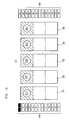
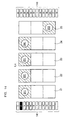
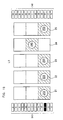
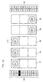
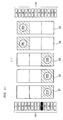
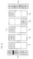
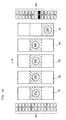
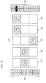
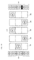
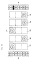
with reference to Figs. 11 to 35. Figs. 11 to 35 are diagrams
each showing one pay line shaded.
As indicated by the shaded parts in Fig. 11, a first pay
line L1 spans the second stop areas 212, 222, 232, 242 and 252.
As indicated by the shaded parts in Fig. 12, a second pay line
L2 spans the first stop areas 211, 221, 231, 241 and 251. As
indicated by the shaded parts in Fig. 13, a third pay line L3
spans the third stop areas 213, 223, 233, 243 and 253. As
indicated by the shaded parts in Fig. 14, a fourth pay line
L4 spans the first stop areas 211, 221, 231 and 241 and the
third stop area 253. As indicated by the shaded parts in Fig.
15, a fifth pay line L5 spans the first stop area 251 and the
third stop areas 213, 223, 233 and 243. As indicated by the
shaded parts in Fig. 16, a sixth pay line L6 spans the first
stop areas 211, 221, 231 and 241 and the second stop area 252.
As indicated by the shaded parts in Fig. 17, a seventh pay line
L7 spans the second stop area 252 and the third stop areas 213,
223, 233 and 243. As indicated by the shaded parts in Fig.
18, an eighth pay line L8 spans the first stop areas 211, 221,
231 and 251 and the second stop area 242. As indicated by the
shaded parts in Fig. 19, a ninth pay line L9 spans the second
stop area 242 and the third stop areas 213, 223, 233 and 253.
As indicated by the shaded parts in Fig. 20, a tenth pay line
L10 spans the first stop areas 211, 221 and 231 and the third
stop areas 243 and 253. As indicated by the shaded parts in
Fig. 21, an eleventh pay line L11 spans the first stop areas
241 and 251 and the third stop areas 213, 223 and 233. As
indicated by the shaded parts in Fig. 22, a twelfth pay line
L12 spans the first stop areas 211, 221, 231 and 251 and the
third stop area 243. As indicated by the shaded parts in Fig.
23, a thirteenth pay line L13 spans the first stop area 241
and the third stop areas 213, 223, 233 and 253. As indicated
by the shaded parts in Fig. 24, a fourteenth pay line L14 spans
the first stop areas 241 and 251 and the second stop areas 212,
222 and 232. As indicated by the shaded parts in Fig. 25, a
fifteenth pay line L15 spans the second stop areas 212, 222
and 232 and the third stop areas 243 and 253. As indicated
by the shaded parts in Fig. 26, a sixteenth pay line L16 spans
the first stop area 241 and the second stop areas 212, 222,
232 and 252. As indicated by the shaded parts in Fig. 27, a
seventeenth pay line L17 spans the second stop areas 212, 222,
232 and 252 and the third stop area 243. As indicated by the
shaded parts in Fig. 28, an eighteenth pay line L18 spans the
first stop area 251 and the second stop areas 212, 222, 232
and 242. As indicated by the shaded parts in Fig. 29, a
nineteenth pay line L19 spans the second stop areas 212, 222,
232 and 242 and the third stop area 253. As indicated by the
shaded parts in Fig. 30, a twentieth pay line L20 spans the
first stop areas 241 and 251, the second stop areas 212 and
222 and the third stop area 233. As indicated by the shaded
parts in Fig. 31, a twenty first pay line L21 spans the first
stop area 231, the second stop areas 212 and 222 and the third
stop areas 243 and 253. As indicated by the shaded parts in
Fig. 32, a twenty second pay line L22 spans the first stop areas
221 and 241, the second stop area 212 and the third stop areas
233 and 253. As indicated by the shaded parts in Fig. 33, a
twenty third pay line L23 spans the first stop areas 231 and
251, the second stop area 212 and the third stop areas 223 and
243. As indicated by the shaded parts in Fig. 34, a twenty
fourth pay line L24 spans the first stop areas 211 and 231 and
the third stop areas 223, 243 and 253. As indicated by the
shaded parts in Fig. 35, a twenty fifth pay line L25 spans the
first stop areas 221, 241 and 251 and the third stop areas 213
and 233.
The "activated pay line" refers to a pay line made
activated among 25 pay lines.
As shown in Figs. 10 to 35, select button groups 141 each
including 25 select buttons formed on the touch panel 121 are
provided on the left of the variable display portion 21 and
on the right of the variable display portion 25, respectively.
The first pay line L1 is selected by touching a select
button having the display, "1", in the select button group 141.
In this case, as shown in Fig. 11, the select button having
the display, "1", is inverted, and the second stop areas 212,
222, 232, 242 and 252 forming the first pay line L1 are also
inverted.
The second pay line L2 is selected by touching a select
button having the display, "2", in the select button group 141.
In this case, as shown in Fig. 12, the select button having
the display, "2", is inverted, and the first stop areas 211,
221, 231, 241 and 251 forming the second pay line L2 are also
inverted.
The third pay line L3 is selected by touching a select
button having the display, "3", in the select button group 141.
In this case, as shown in Fig. 13, the select button having
the display, "3", is inverted, and the third stop areas 213,
223, 233, 243 and 253 forming the third pay line L3 are also
inverted.
The fourth pay line L4 is selected by touching a select
button having the display, "4", in the select button group 141.
In this case, as shown in Fig. 14, the select button having
the display, "4", is inverted, and the first stop areas 211,
221, 231 and 241 and third stop area 253 forming the fourth
pay line L4 are also inverted.
The fifth pay line L5 is selected by touching a select
button having the display, "5", in the select button group 141.
In this case, as shown in Fig. 15, the select button having
the display, "5", is inverted, and the first stop area 251 and
third stop areas 213, 223, 233 and 243 forming the fifth pay
line L5 are also inverted.
The sixth pay line L6 is selected by touching a select
button having the display, "6", in the select button group 141.
In this case, as shown in Fig. 16, the select button having
the display, "6", is inverted, and the first stop areas 211,
221, 231 and 241 and second stop area 252 forming the sixth
pay line L6 are also inverted.
The seventh pay line L7 is selected by touching a select
button having the display, "7", in the select button group 141.
In this case, as shown in Fig. 17, the select button having
the display, "7", is inverted, and the second stop area 252
and third stop areas 213, 223, 233 and 243 forming the seventh
pay line L7 are also inverted.
The eighth pay line L8 is selected by touching a select
button having the display, "8", in the select button group 141.
In this case, as shown in Fig. 18, the select button having
the display, "8", is inverted, and the first stop areas 211,
221, 231 and 251 and second stop area 242 forming the eighth
pay line L8 are also inverted.
The ninth pay line L9 is selected by touching a select
button having the display, "9", in the select button group 141.
In this case, as shown in Fig. 19, the select button having
the display, "9", is inverted, and the second stop area 242
and third stop areas 213, 223, 233 and 253 forming the ninth
pay line L9 are also inverted.
The tenth pay line L10 is selected by touching a select
button having the display, "10", in the select button group
141. In this case, as shown in Fig. 20, the select button having
the display, "10", is inverted, and the first stop areas 211,
221 and 231 and third stop areas 243 and 253 forming the tenth
pay line L10 are also inverted.
The eleventh pay line L11 is selected by touching a select
button having the display, "11", in the select button group
141. In this case, as shown in Fig. 21, the select button having
the display, "11", is inverted, and the first stop areas 241
and 251 and third stop areas 213, 223 and 233 forming the
eleventh pay line L11 are also inverted.
The twelfth pay line L12 is selected by touching a select
button having the display, "12", in the select button group
141. In this case, as shown in Fig. 22, the select button having
the display, "12", is inverted, and the first stop areas 211,
221, 231 and 251 and third stop area 243 forming the twelfth
pay line L12 are also inverted.
The thirteenth pay line L13 is selected by touching a
select button having the display, "13", in the select button
group 141. In this case, as shown in Fig. 23, the select button
having the display, "13", is inverted, and the first stop area
241 and third stop areas 213, 223, 233 and 253 forming the
thirteenth pay line L13 are also inverted.
The fourteenth pay line L14 is selected by touching a
select button having the display, "14", in the select button
group 141. In this case, as shown in Fig. 24, the select button
having the display, "14", is inverted, and the first stop areas
241 and 251 and second stop areas 212, 222 and 232 forming the
fourteenth pay line L14 are also inverted.
The fifteenth pay line L15 is selected by touching a
select button having the display, "15", in the select button
group 141. In this case, as shown in Fig. 25, the select button
having the display, "15", is inverted, and the second stop areas
212, 222 and 232 and third stop areas 243 and 253 forming the
fifteenth pay line L15 are also inverted.
The sixteenth pay line L16 is selected by touching a
select button having the display, "16", in the select button
group 141. In this case, as shown in Fig. 26, the select button
having the display, "16", is inverted, and the first stop area
241 and second stop areas 212, 222, 232 and 252 forming the
sixteenth pay line L16 are also inverted.
The seventeenth pay line L17 is selected by touching a
select button having the display, "17", in the select button
group 141. In this case, as shown in Fig. 27, the select button
having the display, "17", is inverted, and the second stop areas
212, 222, 232 and 252 and third stop area 243 forming the
seventeenth pay line L17 are also inverted.
The eighteenth pay line L18 is selected by touching a
select button having the display, "18", in the select button
group 141. In this case, as shown in Fig. 28, the select button
having the display, "18", is inverted, and the first stop area
251 and second stop areas 212, 222, 232 and 242 forming the
eighteenth pay line L18 are also inverted.
The nineteenth pay line L19 is selected by touching a
select button having the display, "19", in the select button
group 141. In this case, as shown in Fig. 29, the select button
having the display, "19", is inverted, and the second stop areas
212, 222, 232 and 242 and third stop area 253 forming the
nineteenth pay line L19 are also inverted.
The twentieth pay line L20 is selected by touching a
select button having the display, "20", in the select button
group 141. In this case, as shown in Fig. 30, the select button
having the display, "20", is inverted, and the first stop areas
241 and 251, second stop areas 212 and 222 and third stop area
233 forming the twentieth pay line L20 are also inverted.
The twenty first pay line L21 is selected by touching
a select button having the display, "21", in the select button
group 141. In this case, as shown in Fig. 31, the select button
having the display, "21", is inverted, and the first stop area
231, second stop areas 212 and 222 and third stop areas 243
and 253 forming the twenty first pay line L21 are also inverted.
The twenty second pay line L22 is selected by touching
a select button having the display, "22", in the select button
group 141. In this case, as shown in Fig. 32, the select button
having the display, "22", is inverted, and the first stop areas
221 and 241, second stop area 212 and the third stop areas 233
and 253 forming the twenty second pay line L22 are also
inverted.
The twenty third pay line L23 is selected by touching
a select button having the display, "23", in the select button
group 141. In this case, as shown in Fig. 33, the select button
having the display, "23", is inverted, and the first stop areas
231 and 251, second stop area 212 and third stop areas 223 and
243 forming the twenty third pay line L23 are also inverted.
The twenty fourth pay line L24 is selected by touching
a select button having the display, "24", in the select button
group 141. In this case, as shown in Fig. 34, the select button
having the display, "24", is inverted, and the first stop areas
211 and 231 and third stop areas 223, 243 and 253 forming the
twenty fourth pay line L24 are also inverted.
The twenty fifth pay line L25 is selected by touching
a select button having the display, "25", in the select button
group 141. In this case, as shown in Fig. 35, the select button
having the display, "25", is inverted, and the first stop areas
221, 241 and 251 and third stop areas 213 and 233 forming the
twenty fifth pay line L25 are also inverted.
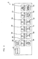
Referring back to Fig. 2, a control table 5 projecting
to the proximal side is provided at the bottom of the lower
liquid crystal display 4. As shown in Fig. 3, COLLECT button
31 and GAME RULES button 32 in order from the leftmost side
are placed in the upper part of control table 5. BET 1 PER
LINE button 33, BET 2 PER LINE button 34, BET 3 PER LINE button
35, BET 5 PER LINE button 36, BET 8 PER LINE button 37 and WIN
START FEATURE button 38 in order from the leftmost side are
placed in the middle part of control table 5. RED PLAY 1 LINE
button 39, PLAY 2 LINES button 40, PLAY 5 LINES button 41, PLAY
20 LINES button 42, BLACK PLAY 25 LINES button 43 and GAMBLE
RESERVE button 44 in order from the leftmost side are placed
in the lower part of control table 5. As shown in Fig. 2, a
coin insertion slot 9 and a bill insertion slot 10 are provided
on the right of the control table 5.
COLLECT button 31 is a button to be pressed upon exit
from a base game. When COLLECT button 31 is pressed, the number
of coins equivalent to the credit value acquired in the game
are paid out through a coin payout opening 15 and received in
a coin tray 16. COLLECT button 31 is associated with COLLECT
switch 45 (see Fig. 4). When COLLECT button 31 is pressed,
a switch signal is output from COLLECT switch 45 to a CPU 50.
GAME RULES button 32 is a button to be pressed when how
the game should be operated is not clear to a player. When
GAME RULES button 32 is pressed, help information is displayed
on the upper liquid crystal display 3 and/or lower liquid
crystal display 4. GAME RULES button 32 is associated with
GAME RULES switch 46 (see Fig. 4). When GAME RULES button 32
is pressed, a switch signal is output from GAME RULES switch
46 to the CPU 50.
The coin insertion slot 9 has a coin sensor 49 (see Fig.
4). When a coin or coins is or are inserted through the coin
insertion slot 9, a coin detection signal is output from the
coin sensor 49 to the CPU 50, and a credit value equivalent
to the inserted coins is added.
The bill insertion slot 10 has a bill sensor 67 (see Fig.
4). When a bill or bills is or are inserted through the bill
insertion slot 10, a bill detection signal is output from the
bill sensor 67 to the CPU 50, and a credit value equivalent
to the inserted bills is added.
BET 1 PER LINE button 33 is a button for betting 1 for
each activated pay line every time pressed once. BET 1 PER
LINE button 33 is associated with 1-BET switch 57 (see Fig.
4). When BET 1 PER LINE button 33 is pressed, a switch signal
is output from 1-BET switch 57 to the CPU 50.
BET 2 PER LINE button 34 is a button for starting a game
with a BET value of 2 for each activated pay line. BET 2 PER
LINE button 34 is associated with 2-BET switch 58 (see Fig.
4). When BET 2 PER LINE button 34 is pressed, a switch signal
is output from 2-BET switch 58 to the CPU 50.
BET 3 PER LINE button 35 is a button for starting a game
with a BET value of 3 for each activated pay line. BET 3 PER
LINE button 35 is associated with 3-BET switch 59 (see Fig.
4). When BET 3 PER LINE button 35 is pressed, a switch signal
is output from 3-BET switch 59 to the CPU 50.
BET 5 PER LINE button 36 is a button for starting a game
with a BET value of 5 for each activated pay line. BET 5 PER
LINE button 36 is associated with 5-BET switch 60 (see Fig.
4). When BET 5 PER LINE button 36 is pressed, a switch signal
is output from 5-BET switch 60 to the CPU 50.
BET 8 PER LINE button 37 is a button for starting a game
with a BET value of 8 for each activated pay line. BET 8 PER
LINE button 37 is associated with 8-BET switch 61 (see Fig.
4). When BET 8 PER LINE button 37 is pressed, a switch signal
is output from 8-BET switch 61 to the CPU 50.
Accordingly, pressing BET 1 PER LINE button 33, BET 2
PER LINE button 34, BET 3 PER LINE button 35, BET 5 PER LINE
button 36 and BET 8 PER LINE button 37 provides a BET value
of 1, 2, 3, 5 and 8, respectively.
WIN START FEATURE button 38 is a button for starting a
bonus game or adding the payout number acquired in the bonus
game to the credit value. WIN START FEATURE button 38 is
associated with WIN-START switch 47 (see Fig. 4). When WIN
START FEATURE button 38 is pressed, a switch signal is output
from WIN-START switch 47 to the CPU 50.
RED PLAY 1 LINE button 39 is a button for starting a game
with the pay line L1 activated and with the number of the
activated pay lines "1". RED PLAY 1 LINE button 39 is
associated with 1-LINE switch 62 (see Fig. 4). When RED PLAY
1 LINE button 39 is pressed, a switch signal is output from
1-LINE switch 62 to the CPU 50.
PLAY 2 LINES button 40 is a button for starting a game
with the pay lines L1 and L2 activated and with the number of
the activated pay lines "2". PLAY 2 LINES button 40 is
associated with 2-LINES switch 63 (see Fig. 4).. When PLAY 2
LINES button 40 is pressed, a switch signal is output from
2-LINES switch 63 to the CPU 50.
PLAY 5 LINES button 41 is a button for starting a game
with the pay lines L1 to L5 activated and with the number of
the activated pay lines "5". PLAY 5 LINES button 41 is
associated with 5-LINES switch 64 (see Fig. 4). When PLAY 5
LINES button 41 is pressed, a switch signal is output from
5-LINES switch 64 to the CPU 50.
PLAY 20 LINES button 42 is a button for starting a game
with the pay lines L1 and L20 activated and with the number
of the activated pay lines "20". PLAY 20 LINES button 42 is
associated with 20-LINES switch 65 (see Fig. 4). When PLAY
20 LINES button 42 is pressed, a switch signal is output from
20-LINES switch 65 to the CPU 50.
BLACK PLAY 25 LINES button 43 is a button for starting
a game with the pay lines L1 and L25 activated and with the
number of the activated pay lines "25". BLACK PLAY 25 LINES
button 43 is associated with 25-LINES switch 66 (see Fig. 4).
When BLACK PLAY 25 LINES button 43 is pressed, a switch signal
is output from 25-LINES switch 66 to the CPU 50.
Accordingly, pressing RED PLAY 1 LINE button 39, PLAY
2 LINES button 40, PLAY 5 LINES button 41, PLAY 20 LINES button
42 and BLACK PLAY 25 LINES button 43 provides the number of
activated pay lines of "1", "2", "5", "20" and "25",
respectively.
Further, RED PLAY 1 LINE button 39, PLAY 2 LINES button
40, PLAY 5 LINES button 41, PLAY 20 LINES button 42, and BLACK
PLAY 25 LINES button 43 are buttons for starting a game with
the current BET value.
RED PLAY 1 LINE button 39 and BLACK PLAY 25 LINES button
43 are also used for selecting red or black in a double down
game, which is performed with the credit value acquired in a
bonus game.
GAMBLE RESERVE button 44 is a button to be pressed when
a player leaves his/her sheet or for shifting to a double down
game after a bonus game. GAMBLE RESERVE button 44 is associated
with GAMBLE-RESERVE switch 48 (see Fig. 4). When GAMBLE
RESERVE button 44 is pressed, a switch signal is output from
GAMBLE-RESERVE switch 48 to the CPU 50.
The cabinet 2 has the coin payout opening 15 and coin
tray 16 in the lower part. The coin tray 16 receives a coin
or coins paid out through the coin payout opening 15. A coin
detection unit 73 (see Fig. 4) including a sensor is placed
in the coin payout opening 15. The coin detection unit 73
detects the number of coins to be paid out through the coin
payout opening 15.
Next, with reference to Fig. 6, columns of symbols, which
are scrolled in the variable display portions 21 to 25 on the
lower liquid crystal display 4 so that symbols included in the
columns are variably displayed, in a base game will be described.
A column of symbols indicated on a first reel band 101 is
scrolled in the variable display portion 21. A column of
symbols indicated on a second reel band 102 is scrolled in the
variable display portion 22. A column of symbols indicated
on a third reel band 103 is scrolled in the variable display
portion 23. A column of symbols indicated on a fourth reel
band 104 is scrolled in the variable display portion 24. A
column of symbols indicated on a fifth reel band 105 is scrolled
in the variable display portion 25.
The columns of symbols indicated on the reel bands 101
to 105 have symbol arrangements, which are different from each
other. Each of the columns of symbols has a combination of
twelve symbols of "LOBSTER", "SHARK", "FISH", "PUNK",
"OCTOPUS", "CRAB", "WORM", "A", "K", "Q", "J" and "SARDINE".
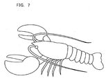
"LOBSTER" refers to a lobster symbol as shown in Fig. 7. "SHARK",
"FISH", "PUNK", "OCTOPUS", "CRAB", "WORM" and "SARDINE" refer
to shark, fish, punk, octopus, crab, worm and sardine symbols,
not shown, respectively. "A", "K", "Q" and "J" refer to
alphabetical symbols corresponding thereto. "SARDINE" also
functions as a scatter symbol for shifting to a bonus game as
described later. When three or more "SARDINE" symbols are
stopped in the variable display portions 21 to 25 in total,
the shift to a bonus game is allowed independent of activated
pay lines.
Three symbols are stopped in each of the variable display
portions 21 to 25 after the columns of symbols indicated on
the reel bands 101 to 105 are scrolled in the variable display
portions 21 to 25 and then stopped.
Winning combinations are predefined based on multiple
kinds of combination of symbols. When a winning combination
is made on an activated pay line, a payout number of the winning
combination is added to the credit value, the mechanism of which
is similar to that of a conventional slot machine and therefore
the detailed explanation is omitted herein.
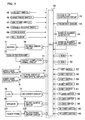
Next, a construction of a control system of the slot
machine 1 will be described with reference to Fig. 4.
The control system of the slot machine 1 includes the
CPU 50 as a core, which is connected to a ROM 51 and a RAM 52.
The ROM 51 stores a main processing program, base game
processing program, bonus game processing program, lottery
table of symbols to be stopped in a base game, lottery table
of symbols to be stopped in a bonus game, other programs
required for controlling the slot machine 1, data table, or
the like. The RAM 52 is a memory for temporarily storing data
computed by the CPU 50.
A clock pulse generator circuit 53 for generating a
reference clock pulse, a frequency divider 54, a random number
generator 55 for generating a random number, and a random number
sampling circuit 56 are connected to the CPU 50. Random numbers
sampled by the random number sampling circuit 56 are used in
a lottery for a winning combination. COLLECT switch 45
associated with COLLECT button 31, GAME-RULES switch 46
associated with GAME RULES button 32, 1-BET switch 57
associated with BET 1 PER LINE button 33, 2-BET switch 58
associated with BET 2 PER LINE button 34, 3-BET switch 59
associated with BET 3 PER LINE button 35, 5-BET switch 60
associated with BET 5 PER LINE button 36, 8-BET switch 61
associated with BET 8 PER LINE button 37, WIN-START switch 47
associated with WIN START FEATURE button 38, 1-LINE switch 62
associated with RED PLAY 1 LINE button 39, 2-LINES switch 63
associated with PLAY 2 LINES button 40, 5-LINES switch 64
associated with PLAY 5 LINES button 41, 20-LINES switch 65
associated with PLAY 20 LINES button 42, 25-LINES switch 66
associated with BLACK PLAY 25 LINES button 43 and
GAMBLE-RESERVE switch 48 associated with GAMBLE RESERVE button
44 are further connected to the CPU 50. The CPU 50 receives
a switch signal output from the above-described switch when
the corresponding button is pressed and controls to perform
an operation corresponding to the pressed button.
The coin sensor 49 placed in the coin insertion slot 9
and the bill sensor 67 placed in the bill insertion slot 10
are connected to the CPU 50. The coin sensor 49 detects the
number of coins inserted through the coin insertion slot 9,
and the CPU 50 computes a credit value equivalent to the
inserted coins based on a coin detection signal output from
the coin sensor 49. The bill sensor 67 detects the type and
the number of bills inserted through the bill insertion slot
10 and the amount of money. The CPU 50 computes a credit value
equivalent to the inserted bills based on a bill detection
signal output from the bill sensor 67.
A hopper 71 is connected to the CPU 50 through a hopper
driver circuit 70. When a drive signal is output from the CPU
50 to the hopper driver circuit 70, the hopper 71 pays out a
predetermined number of coins through the coin payout opening
15.
The coin detection unit 73 is further connected to the
CPU 50 through a payout completion signal circuit 72. When
the coin detection unit 73 detects the predetermined number
of coins to be paid out through the coin payout opening 15,
a coin payout detection signal is output from the coin detection
unit 73 to the payout completion signal circuit 72. Based on
the coin payout detection signal, the payout completion signal
circuit 72 outputs a payout completion signal to the CPU 50.
The upper liquid crystal display 3 and lower liquid
crystal display 4, which are further connected to the CPU 50
through a control circuit 74 of the liquid crystal displays
3 and 4, are controlled by the CPU 50.
As shown in Fig. 5, the control circuit 74 includes a
program ROM 81, an image ROM 82, an image control CPU 83, a
work RAM 84, a video display processor (VDP) 85, and a video
RAM 86. The program ROM 81 stores an image control program
and various select tables relating to the displays on the upper
liquid crystal display 3 and lower liquid crystal display 4.
The image ROM 82 stores dot data for forming an image such as
the columns of symbols indicated on the reel bands 101 to 105
in Fig. 6 displayed on the lower liquid crystal display 4 (or
in the variable display portions 21 to 25). The image control
CPU 83 determines an image to be displayed on the upper liquid
crystal display 3 or lower liquid crystal display 4 from dot
data prestored in the image ROM 82 based on a parameter defined
by the CPU 50 and in accordance with an image control program
prestored in the program ROM 81. The work RAM 84 functions
as a temporary storage device to be used for executing the image
control program by the image control CPU 83. The VDP 85 forms
an image determined by the image control CPU 83 and outputs
the result to the upper liquid crystal display 3 or lower liquid
crystal display 4. Thus, the columns of symbols indicated on
the reel bands 101 to 105 are scrolled on the lower liquid
crystal display 4 (or in the variable display portions 21 to
25). The video RAM 86 functions as a temporary storage device
to be used for forming an image by the VDP 85.
A number of LEDs 78 (one of which is shown in Fig. 4)
placed on the front face of the slot machine 1 are further
connected to the CPU 50 through an LED driver circuit 77
controlling the lighting of the LED 78 based on a drive signal
from the CPU 50 for various effects. A sound output circuit
79 and a speaker 80 are further connected to the CPU 50. The
speaker 80 produces various sound effects based on output
signals from the sound output circuit 79.
The touch panel 121 provided on the screen of the lower
liquid crystal display 4 is further connected to the CPU 50
through a touch panel driver circuit 122. When one of the 25
select buttons included in the select button group 141 on the
touch panel 121 is touched, the touch panel 121 detects the
touched select button.
Next, the determination of symbols to be stopped on the
activated pay line L1 in a base game by using a lottery table
shown in Fig. 9 will be described.
Symbols to be stopped on the activated pay line L1 are
determined for each of the variable display portions 21 to 25.
Code numbers of "00" to "29" are sequentially assigned to
symbols included in each of the columns (see Fig. 6) scrolled
in the variable display portions 21 to 25, respectively, while
the lottery table shown in Fig. 9 is provided. Five random
numbers corresponding to the variable display portions 21 to
25, respectively, are sampled by the random number sampling
circuit 56.
Here, with reference to Figs. 6 and 9, the determination
of a symbol to be stopped on the activated pay line L1 in the
variable display portion 21, i.e., stopped in the second stop
area 212 (see Fig. 11), will be described.
When the random number sampled by the random number
sampling circuit 56 is "0", the "J" symbol assigned to Code
Number "00" is stopped in the second stop area 212. When the
random number is "1", the "Q" symbol assigned to Code Number
"01" is stopped in the second stop area 212. When the random
number is "2", the "LOBSTER" symbol (see Fig. 7) assigned to
Code Number "02" is stopped in the second stop area 212. When
the random number is "3", the "J" symbol assigned to Code Number
"03" is stopped in the second stop area 212. When the random
number is "4", the "Q" symbol assigned to Code Number "04" is
stopped in the second stop area 212. When the random number
is "5", the "CRAB" symbol assigned to Code Number "05" is
stopped in the second stop area 212. When the random number
is "6", the "A" symbol assigned to Code Number "06" is stopped
in the second stop area 212. When the random number is "7",
the "WORM" symbol assigned to Code Number "07" is stopped in
the second stop area 212. When the random number is "8", the
"K" symbol assigned to Code Number "08" is stopped in the second
stop area 212. When the random number is "9", the "FISH" symbol
assigned to Code Number "09" is stopped in the second stop area
212. When the random number is "10", the "PUNK" symbol assigned
to Code Number "10" is stopped in the second stop area 212.
When the random number is "11", the "Q" symbol assigned to Code
Number "11" is stopped in the second stop area 212. When the
random number is "12", the "SHARK" symbol assigned to Code
Number "12" is stopped in the second stop area 212. When the
random number is "13", the "CRAB" symbol assigned to Code Number
"13" is stopped in the second stop area 212. When the random
number is "14", the "K" symbol assigned to Code Number "14"
is stopped in the second stop area 212. When the random number
is "15", the "A" symbol assigned to Code Number "15" is stopped
in the second stop area 212. When the random number is "16",
the "OCTOPUS" symbol assigned to Code Number "16" is stopped
in the second stop area 212. When the random number is "17",
the "J" symbol assigned to Code Number "17" is stopped in the
second stop area 212. When the random number is "18", the "Q"
symbol assigned to Code Number "18" is stopped in the second
stop area 212. When the random number is "19", the "FISH"
symbol assigned to Code Number "19" is stopped in the second
stop area 212. When the random number is "20", the "K" symbol
assigned to Code Number "20" is stopped in the second stop area
212. When the random number is "21", the "J" symbol assigned
to Code Number "21" is stopped in the second stop area 212.
When the random number is "22", the "SARDINE" symbol assigned
to Code Number "22" is stopped in the second stop area 212.
When the random number is "23", the "CRAB" symbol assigned to
Code Number "23" is stopped in the second stop area 212. When
the random number is "24", the "J" symbol assigned to Code
Number "24" is stopped in the second stop area 212. When the
random number is "25", the "WORM" symbol assigned to Code Number
"25" is stopped in the second stop area 212. When the random
number is "26", the "Q" symbol assigned to Code Number "26"
is stopped in the second stop area 212. When the random number
is "27", the "CRAB" symbol assigned to Code Number "27" is
stopped in the second stop area 212. When the random number
is "28", the "A" symbol assigned to Code Number "28" is stopped
in the second stop area 212. When the random number is "29",
the "FISH" symbol assigned to Code Number "29" is stopped in
the second stop area 212.
Symbols to be stopped on the activated pay line L1 in
the variable display portions 22 to 25 other than the variable
display portion 21 are determined in the same manner as above.
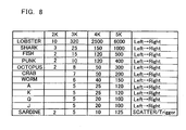
Next, winning combinations and payout numbers thereof
in a base game will be described with reference to Fig. 8. Fig.
8 is an explanatory diagram showing winning combinations and
payout numbers thereof in a base game for a BET value of "1".
For winning combinations other than that of "SARDINE"
symbol, the payout number shown in Fig. 8 is added to the credit
value when the BET value is "1", while, when the BET value is
"2" or a higher number, the value resulting from the
multiplication of the payout number shown in Fig. 8 by the BET
value is added to the credit value. When two ore more winning
combinations of symbols other than "SARDINE" symbol are
simultaneously made on more than two activated pay lines,
respectively, the total of the payout numbers is added to the
credit value. On the other hand, for the winning combination
of "SARDINE" symbol only, the value resulting from the
multiplication of the payout number by a total BET value, i.e.,
the product of BET value and number of activated pay lines,
is added to the credit value. When one or more winning
combinations of symbols other than "SARDINE" symbol are
simultaneously made in addition to the winning combination of
the "SARDINE" symbol, the payout number(s) for the additional
winning combination (s) is/are also added to the credit value.
More specifically, stopping the "LOBSTER" symbols in a
row on an activated pay line in the variable display portions
21 and 22 (in the case of "2K" indicating that two of the symbols
appear continuously from the left end) results in a payout
number of "10". Stopping the "LOBSTER" symbols in a row on
an activated pay line in the variable display portions 21 to
23 (in the case of "3K" indicating that three of the symbols
appear continuously from the left end) results in a payout
number of "320". Stopping the "LOBSTER" symbols in a row on
an activated pay line in the variable display portions 21 to
24 (in the case of "4K" indicating that four of the symbols
appear continuously from the left end) results in a payout
number of "2500". Stopping the "LOBSTER" symbols in a row on
an activated pay line in the variable display portions 21 to
25 (in the case of "5K" indicating that five of the symbols
appear continuously from the left end) results in a payout
number of "6000".
Stopping the "SHARK" symbols in a row on an activated
pay line in the variable display portions 21 and 22 (in the
case of "2K" indicating that two of the symbols appear
continuously from the left end) results in a payout number of
"3". Stopping the "SHARK" symbols in a row on an activated
pay line in the variable display portions 21 to 23 (in the case
of "3K" indicating that three of the symbols appear
continuously from the left end) results in a payout number of
"25". Stopping the "SHARK" symbols in a row on an activated
pay line in the variable display portions 21 to 24 (in the case
of "4K" indicating that four of the symbols appear continuously
from the left end) results in a payout number of "150".
Stopping the "SHARK" symbols in a row on an activated pay line
in the variable display portions 21 to 25 (in the case of "5K"
indicating that five of the symbols appear continuously from
the left end) results in a payout number of "1000".
Stopping the "FISH" symbols in a row on an activated pay
line in the variable display portions 21 and 22 (in the case
of "2K" indicating that two of the symbols appear continuously
from the left end) results in a payout number of "2". Stopping
the "FISH" symbols in a row on an activated pay line in the
variable display portions 21 to 23 (in the case of "3K"
indicating that three of the symbols appear continuously from
the left end) results in a payout number of "15". Stopping
the "FISH" symbols in a row on an activated pay line in the
variable display portions 21 to 24 (in the case of "4K"
indicating that four of the symbols appear continuously from
the left end) results in a payout number of "120". Stopping
the "FISH" symbols in a row on an activated pay line in the
variable display portions 21 to 25 (in the case of "5K"
indicating that five of the symbols appear continuously from
the left end) results in a payout number of "500".
Stopping the "PUNK" symbols in a row on an activated pay
line in the variable display portions 21 and 22 (in the case
of "2K" indicating that two of the symbols appear continuously
from the left end) results in a payout number of "2". Stopping
the "PUNK" symbols in a row on an activated pay line in the
variable display portions 21 to 23 (in the case of "3K"
indicating that three of the symbols appear continuously from
the left end) results in a payout number of "10". Stopping
the "PUNK" symbols in a row on an activated pay line in the
variable display portions 21 to 24 (in the case of "4K"
indicating that four of the symbols appear continuously from
the left end) results in a payout number of "120". Stopping
the "PUNK" symbols in a row on an activated pay line in the
variable display portions 21 to 25 (in the case of "5K"
indicating that five of the symbols appear continuously from
the left end) results in a payout number of "400".
Stopping the "OCTOPUS" symbols in a row on an activated
pay line in the variable display portions 21 and 22 (in the
case of "2K" indicating that two of the symbols appear
continuously from the left end) results in a payout number of
"2". Stopping the "OCTOPUS" symbols in a row on an activated
pay line in the variable display portions 21 to 23 (in the case
of "3K" indicating that three of the symbols appear
continuously from the left end) results in a payout number of
"8". Stopping the "OCTOPUS" symbols in a row on an activated
pay line in the variable display portions 21 to 24 (in the case
of "4K" indicating that four of the symbols appear continuously
from the left end) results in a payout number of "50". Stopping
the "OCTOPUS" symbols in a row on an activated pay line in the
variable display portions 21 to 25 (in the case of "5K"
indicating that five of the symbols appear continuously from
the left end) results in a payout number of "300".
Stopping the "CRAB" symbols in a row on an activated pay
line in the variable display portions 21 to 23 (in the case
of "3K" indicating that three of the symbols appear
continuously from the left end) results in a payout number of
"7". Stopping the "CRAB" symbols in a row on an activated pay
line in the variable display portions 21 to 24 (in the case
of "4K" indicating that four of the symbols appear continuously
from the left end) results in a payout number of "50". Stopping
the "CRAB" symbols in a row on an activated pay line in the
variable display portions 21 to 25 (in the case of "5K"
indicating that five of the symbols appear continuously from
the left end) results in a payout number of "200".
Stopping the "WORM" symbols in a row on an activated pay
line in the variable display portions 21 to 23 (in the case
of "3K" indicating that three of the symbols appear
continuously from the left end) results in a payout number of
"6". Stopping the "WORM" symbols in a row on an activated pay
line in the variable display portions 21 to 24 (in the case
of "4K" indicating that four of the symbols appear continuously
from the left end) results in a payout number of "40". Stopping
the "WORM" symbols in a row on an activated pay line in the
variable display portions 21 to 25 (in the case of "5K"
indicating that five of the symbols appear continuously from
the left end) results in a payout number of "150".
Stopping the "A" symbols in a row on an activated pay
line in the variable display portions 21 to 23 (in the case
of "3K" indicating that three of the symbols appear
continuously from the left end) results in a payout number of
"5". Stopping the "A" symbols in a row on an activated pay
line in the variable display portions 21 to 24 (in the case
of "4K" indicating that four of the symbols appear continuously
from the left end) results in a payout number of "25". Stopping
the "A" symbols in a row on an activated pay line in the variable
display portions 21 to 25 (in the case of "5K" indicating that
five of the symbols appear continuously from the left end)
results in a payout number of "120".
Stopping the "K" symbols in a row on an activated pay
line in the variable display portions 21 to 23 (in the case
of "3K" indicating that three of the symbols appear
continuously from the left end) results in a payout number of
"5". Stopping the "K" symbols in a row on an activated pay
line in the variable display portions 21 to 24 (in the case
of "4K" indicating that four of the symbols appear continuously
from the left end) results in a payout number of "25". Stopping
the "K" symbols in a row on an activated pay line in the variable
display portions 21 to 25 (in the case of "5K" indicating that
five of the symbols appear continuously from the left end)
results in a payout number of "120".
Stopping the "Q" symbols in a row on an activated pay
line in the variable display portions 21 to 23 (in the case
of "3K" indicating that three of the symbols appear
continuously from the left end) results in a payout number of
"5". Stopping the "Q" symbols in a row on an activated pay
line in the variable display portions 21 to 24 (in the case
of "4K" indicating that four of the symbols appear continuously
from the left end) results in a payout number of "20". Stopping
the "Q" symbols in a row on an activated pay line in the variable
display portions 21 to 25 (in the case of "5K" indicating that
five of the symbols appear continuously from the left end)
results in a payout number of "100".
Stopping the "J" symbols in a row on an activated pay
line in the variable display portions 21 to 23 (in the case
of "3K" indicating that three of the symbols appear
continuously from the left end) results in a payout number of
"5". Stopping the "J" symbols in a row on an activated pay
line in the variable display portions 21 to 24 (in the case
of "4K" indicating that four of the symbols appear continuously
from the left end) results in a payout number of "20". Stopping
the "J" symbols in a row on an activated pay line in the variable
display portions 21 to 25 (in the case of "5K" indicating that
five of the symbols appear continuously from the left end)
results in a payout number of "100".
On the other hand, winning combinations of the "SARDINE"
symbol, unlike those of the above symbols, are independent of
an activated pay line. More specifically, stopping the
"SARDINE" symbol in two, three, four, and five of the variable
display portions 21 to 25, not limited to an activated pay line,
results in a payout number of "2" (in the case of "2K"), "5"
(in the case of "3K"), "10" (in the case of "4K"), and "125"
(in the case of "5K"), respectively.
Further, stopping the "SARDINE" symbol in three or more
of the variable display portions 21 to 25, not limited to an
activated pay line, results in an award of a payout and the
shift to a bonus game.
The "bonus game" refers to a game to be performed after
a base game and may generally be a more advantageous game to
a player. Here, in the bonus game, 15 to 25 games are
automatically implemented in accordance with a lottery result
on the shift to the bonus game without betting any credit, for
example.
In a bonus game, columns of symbols, which are scrolled
in the variable display portions 21 to 25 on the lower liquid
crystal display 4 so that symbols included in the columns are
variably displayed, are shown in Fig. 42. Columns of symbols
indicated on first, second, third, fourth, and fifth reel bands
123, 124, 125, 126, and 127 are scrolled in the variable display
portions 21 to 25, respectively.
The columns of symbols indicated on the reel bands 123
to 126 in Fig. 42, which are used in a bonus game, are identical
to the columns of symbols indicated on the reel bands 101 to
104 in Fig. 6, which are used in a base game. On the other
hand, the column of symbols indicated on the reel band 127 in
Fig. 42 is different from the column of symbols indicated on
the reel band 105 in Fig. 6, only in the "LOBSTER" symbol
assigned to the code number "10".
The BET value and number of activated pay lines in the
bonus game are those upon shift to the bonus game. The winning
combinations and payout numbers thereof in the bonus game are
identical to those of the base game with the exception of the
"SHARK" symbol handled as the "LOBSTER" symbol in the bonus
game. Furthermore, stopping the "SARDINE" symbol in three or
more of the variable display portions 21 to 25, not limited
to an activated pay line, results in the shift to the bonus
game again. Thus, a player can often get higher credit.
Next, a main processing program executed in the slot
machine 1 will be described with reference to Fig. 36.
First, a starting process, which will be detailed later
with reference to Fig. 37, is performed in step ("S" for short
hereinafter) 11. After the starting process is preformed in
S11, a game is started and the processing moves to S12. In
S12, a lottery processing, which will be detailed later with
reference to Fig. 38, is performed. Thereafter the processing
moves to S13 where a base game processing, which will be
detailed later with reference to Fig. 39, is performed. Then,
the processing moves to S14 where whether a bonus game has been
won or not is determined. More specifically, in the lottery
processing in S12, if three or more "SARDINE" symbols are
stopped in the variable display portions 21 to 25 in total,
not limited to an activated pay line, a bonus game is won (YES
in S14). Then, the processing moves to S15 where a bonus game
processing, which will be detailed later with reference to Fig.
40, is performed. After the bonus game processing is performed
in S15, the main processing program ends. On the other hand,
in S12, if three or more "SARDINE" symbols are not stopped in
the variable display portions 21 to 25 in total, not limited
to an activated pay line, no bonus game is won (NO in S14).
Then, the main processing program ends.
Here, the starting process executed in S11 of the main
processing program will be detailed with reference to Fig. 37.
First, in S21, whether a predetermined period of time,
e.g., 15 seconds, has passed or not is determined. If it is
determined that the predetermined period of time has not passed
(NO in S21), the processing moves to S23 without performing
anything. If it is determined that the predetermined period
of time has passed (YES in S21), a demo-effect is implemented
on the upper liquid crystal display 3 and/or lower liquid
crystal display 4 in S22, which is followed by S23.
In S23, whether any one of the BET 1 PER LINE button 33,
BET 2 PER LINE button 34, BET 3 PER LINE button 35, BET 5 PER
LINE button 36 and BET 8 PER LINE button 37 has been pressed
or not is determined based on a switch signal output from one
of the 1-BET switch 57, 2-BET switch 58, 3-BET switch 59, 5-BET
switch 60 and 8-BET switch 61. If it is determined that none
of the above buttons has been pressed (NO in S23), the
processing returns to S21 and repeats the above-described
processing. On the other hand, if it is determined that any
one of the above buttons has been pressed (YES in S23), the
processing moves to S24 even in the middle of the demo-effect.
The determination processing in S23 may be based on not only
the switch signal but also other input signals.
In S24, whether any one of the 25 select buttons included
in the select button group 141 on the touch panel 121 has been
touched or not is determined based on a control signal output
from the touch panel driver circuit 122. If it is determined
that one of the 25 select buttons has been touched (YES in S24),
the processing moves to S26 where an activated pay line
selecting processing, which will be described later with
reference to Fig. 1, is performed. Then, the processing
returns to the main processing program shown in Fig. 36 and
moves to the lottery processing in S12. On the other hand,
if it is determined that none of the 25 select buttons has been
touched (NO in S24), the processing moves to S25.
In S25, whether any one of the RED PLAY 1 LINE button
39, PLAY 2 LINES button 40, PLAY 5 LINES button 41, PLAY 20
LINES button 42 or BLACK PLAY 25 LINES button 43 has been pressed
or not is determined based on a switch signal output from one
of the 1-LINE switch 62, 2-LINES switch 63, 5-LINES switch 64,
20-LINES switch 65 and 25-LINES switch 66. If it is determined
that none of the above buttons has been pressed (NO in S25),
the processing returns to S24 and the above-described
processing is repeated. On the other hand, if it is determined
that one of the above buttons has been pressed (YES in S25),
the processing returns to the main processing program shown
in Fig. 36 and moves to the lottery processing in S12 even in
the middle of the demo effect.
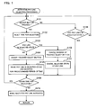
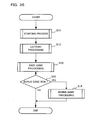
Now, the activated pay line selecting processing program
executed in S26 of the starting process will be described with
reference to Fig. 1.
First, in S101, whether any one of the 25 select buttons
included in the select button group 141 on the touch panel 121
has been touched or not is determined based on a control signal
output from the touch panel driver circuit 122. If it is
determined that one of the 25 select buttons has been touched
(YES in S101), the processing moves to S102 where the time for
selection counted by the clock pulse generator circuit 53 or
the like is reset and the measurement of time is started.
In S103, whether the pay line corresponding to the
touched select button is in a selected state or not is
determined. If it is determined that the pay line
corresponding to the touched select button is not in a selected
state (NO in S103), the processing moves to S104 where the
touched select button is inverted (see Figs. 11 to 35) and
further moves to S105 where the pay line corresponding to the
touched select button is made in a selected state and inverted
for a predetermined period of time (see Figs. 11 to 35). Then,
the processing moves to S108. On the other hand, if it is
determined that the pay line corresponding to the touched
select button in the select button group 141 is in a selected
state (YES in S103), the processing moves to S106 where the
inverse of the touched select button is cancelled and further
moves to S107 where the selected state of the pay line
corresponding to the touched select button is cancelled. Then,
the processing moves to S108.
In S108, whether it is within the time for selection or
not is determined. If it is determined that it is within the
time for selection (YES in S108), the processing returns to
S101 and the above-described processing is repeated. On the
other hand, if it is determined that it is not within the time
for selection (NO in S108), the processing moves to S110 where
the selected pay line is made activated. Then, the processing
returns to the starting process shown in Fig. 37 and further
returns the main processing program shown in Fig. 36 and moves
to the lottery processing in S12.
In S101 described above, if it is determined that none
of the 25 select buttons has been touched (NO in S101), the
processing moves to S109 where whether any one of the pay lines
is in a selected state or not is determined. If it is determined
that none of the pay lines is in a selected state (NO in S109),
the processing returns to S101, and the above-described
processing is repeated. On the other hand, if it is determined
that any one of the pay lines is in a selected state (YES in
S109), the processing moves to S108.
The CPU 50 functions as "select means" when performing
S110 of the activated pay line selecting processing program
shown in Fig. 1. The CPU 50 further functions as "activated
pay line display means" when performing S105 of the activated
pay line selecting processing program. The CPU 50 further
functions as "highlighting means" when performing S104 of the
activated pay line selecting processing program.
Next, the lottery processing program executed in S12 of
the main processing program will be described with reference
to Fig. 38.
First, in S31, symbols to be stopped on the activated
pay line are determined. Here, in a base game, symbols to be
stopped on the activated pay line L1 are determined for each
of the variable display portions 21 to 25. More specifically,
as described above, five random numbers corresponding to the
variable display portions 21 to 25, respectively, are sampled
by the random number sampling circuit 56, and symbols to be
stopped on the activated pay line are determined through code
numbers on the lottery table shown in Fig. 9.
In S32, a winning combination and a payout number thereof
are determined based on the symbol determination in S31 and
on the table shown in Fig. 8. Then, the processing returns
to the main processing program shown in Fig. 36 and moves to
the base game processing in S13.
Here, if a bonus game is won, the number, e.g., one of
10 to 25, of games to be repeatedly performed in the bonus game
is determined by lottery. The bonus game here may be referred
to as free games in the present invention.
Next, the base game processing program executed in S13
of the main processing program will be described with reference
to Fig. 39.
First, in S41, the columns of symbols are scrolled in
the variable display portions 21 to 25. Then, the scrolling
of the columns of symbols is stopped in S42. In S43, credit
is paid out. The credit value corresponds to the payout number,
which is determined based on the winning combination of symbols
stopped in the variable display portions 21 to 25 in S42 and
on the table shown in Fig. 8. Then, the processing returns
to the main processing program shown in Fig. 36 and moves to
S14.
Next, the bonus game processing program executed in S15
of the main processing program will be described with reference
to Fig. 40.
First, in S51, a lottery processing in the bonus game
is performed. In the same manner as the base game, symbols
to be stopped on the activated pay line L1 are determined for
each of the variable display portions 21 to 25. More
specifically, in the same manner as above S31 of the base game
lottery processing shown in Fig. 38, five random numbers
corresponding to the variable display portions 21 to 25,
respectively, are sampled by the random number sampling circuit
56, and symbols to be stopped on the activated pay line are
determined through code numbers on the lottery table shown in
Fig. 9. After the symbols to be stopped on the activated pay
line L1 are determined, a winning combination and a payout
number thereof are determined based on the symbol determination
above and on the table shown in Fig. 8.
In S52, the columns of symbols are automatically scrolled
in the variable display portions 21 to 25. Then, the scrolling
of the columns of symbols is stopped in S53. In S54, credit
is paid out. The credit value corresponds to the payout number,
which is determined based on the winning combination of symbols
stopped in the variable display portions 21 to 25 in S53 and
on the table shown in Fig. 8. It should be noted that the
"SHARK" symbol is handled as the "LOBSTER" symbol here in the
bonus game.
In S55, whether the number of repeatedly performed games
reaches the number determined in the lottery processing shown
in Fig. 38 and described above or not is determined. If it
is determined that the number of repeatedly performed games
has not reached the determined number (NO in S55), the
processing returns to S51 and the above-described processing
is repeated. On the other hand, if it is determined that the
number of repeatedly performed games has reached the determined
number (YES in S55), the bonus game processing program is ended.
In S51 described above, if a bonus game is won, the number
of repeatedly performed games is newly determined. The
determined number is added to the "number determined in the
lottery processing" in the determination in S55. Thus, if a
bonus game is won during a bonus game, the shift to the bonus
game is performed again. For example, when 17 bonus games are
won in the twelfth game of a bonus game of 20 games, the total
of 25 (20-12+17) bonus games are performed thereafter.
Moreover, if credit is paid out in the bonus game, a double
down game that bets the credit is performed after the bonus
game, the description of which will be omitted herein.
The CPU 50 functions as "game control means" when
executing the main processing program shown in Fig. 36.
As described above, in the slot machine 1 of this
embodiment, the 25 select buttons included in the select button
group 141 on the touch panel 121 correspond to the 25 pay lines
L1 to L25, respectively. If one or more of the 25 select buttons
are touched (YES in S101), one or more pay lines corresponding
to the touched select buttons are selected as (an) activated
pay line(s) from the 25 pay lines L1 to L25 (S102 to S110).
Thus, a player can freely select one or more activated pay lines
from pay lines through the select buttons corresponding to the
pay lines, respectively, which can enhance the amusement.
In the slot machine 1 of this embodiment, a pay line is
inverted when selected (S105). Thus, which pay lines are in
a selected state can be easily visually checked even when
multiple pay lines are selectable.
Further, since the select button corresponding to the
pay line selected as an activated pay line is inverted (S104),
which pay lines are in a selected state can be more easily
visually checked even when multiple pay lines are selectable.
Although, in the slot machine 1 of this embodiment, the
selected pay line and the select button corresponding to the
selected pay line are inverted (S104 and S105), the selected
pay line and/or the select button may be highlighted in another
manner such as color display and blinking display. For example,
as shown in Fig. 43, the selected pay line may be displayed
like a line graph. Fig. 43 shows the state that the 25th pay
line is only selected.
Although, in the slot machine 1 of this embodiment, the
select buttons are formed on the touch panel 121, the select
button may be, for example, a lock type press button which emits
light with LEDs.
A spin button may be newly provided to the slot machine
1, and activated pay line selecting processing shown in Fig.
44 as described below may be performed instead of the activated
pay line selecting processing in Fig. 1.
Here, the activated pay line selecting processing
program shown in Fig. 44 will be described.
First, in S121, whether any one of the 25 select buttons
included in the select button group 141 on the touch panel 121
has been touched or not is determined. If it is determined
that one of the 25 select buttons has been touched (YES in S121),
the processing moves to S122 where whether the pay line
corresponding to the touched select button is in a selected
state or not is determined. If it is determined that the pay
line corresponding to the touched select button is not in a
selected state (NO in S122), the processing moves to S123 where
the touched select button is inverted (see Figs. 11 to 35) and
further moves to S124 where the pay line corresponding to the
touched select button is made in a selected state and the pay
line is inverted for a predetermined period of time (Figs. 11
to 35). Then, the processing moves to S127.
On the other hand, if it is determined that the pay line
corresponding to the touched select button is in a selected
state (YES in S122), the processing moves to S125 where the
inverse of the touched select button is cancelled and further
moves to S126 where the selected state of the pay line
corresponding to the touched select button is cancelled. Then,
the processing moves to S127.
In S127, whether the spin button has been pressed or not
is determined. If it is determined that the spin button has
not been pressed (NO in S127), the processing returns to S121
and the above-described processing is repeated. On the other
hand, if it is determined that the spin button has been pressed
(YES in S127), the processing moves to S128 where the selected
pay line is made activated. Then, the processing returns to
the starting process shown in Fig. 37 and further returns to
the main processing program shown in Fig. 36 and moves to the
lottery processing in S12.
In S121 described above, if it is determined that none
of the 25 select buttons has been touched (NO in S121), the
processing returns to S121 itself where the processing waits
until one of the 25 select buttons is touched by a player.
The lottery table used for determining symbols to be
stopped on the activated pay line may be a lottery table shown
in Fig. 41, in which a specific range of random numbers sampled
by the random number sampling circuit 56 corresponds to one
of the code numbers, for example, although the lottery table
shown in Fig. 9, in which one of the random numbers sampled
by the random number sampling circuit 56 corresponds to one
of the code numbers, is applied in this embodiment.
Although the five variable display portions 21 to 25 are
exemplified as variable display portions in this embodiment,
the invention is not limited thereto.
The invention is also applicable to gaming machines
excluding a slot machine.
While this invention has been described in conjunction
with the specific embodiments outlined above, it is evident
that many alternatives, modifications and variations will be
apparent to those skilled in the art. Accordingly, the
preferred embodiments of the invention as set forth above are
intended to be illustrative, not limiting. Various changes
may be made without departing from the spirit and scope of the
invention as defined in the following claims.