EP1591783B1 - Méthode pour la détection et l'analyse des complexes macromoléculaires - Google Patents
Méthode pour la détection et l'analyse des complexes macromoléculaires Download PDFInfo
- Publication number
- EP1591783B1 EP1591783B1 EP04010121A EP04010121A EP1591783B1 EP 1591783 B1 EP1591783 B1 EP 1591783B1 EP 04010121 A EP04010121 A EP 04010121A EP 04010121 A EP04010121 A EP 04010121A EP 1591783 B1 EP1591783 B1 EP 1591783B1
- Authority
- EP
- European Patent Office
- Prior art keywords
- complexes
- gel
- carrier
- macromolecules
- macromolecular
- Prior art date
- Legal status (The legal status is an assumption and is not a legal conclusion. Google has not performed a legal analysis and makes no representation as to the accuracy of the status listed.)
- Expired - Lifetime
Links
Images



Classifications
-
- G—PHYSICS
- G01—MEASURING; TESTING
- G01N—INVESTIGATING OR ANALYSING MATERIALS BY DETERMINING THEIR CHEMICAL OR PHYSICAL PROPERTIES
- G01N27/00—Investigating or analysing materials by the use of electric, electrochemical, or magnetic means
- G01N27/26—Investigating or analysing materials by the use of electric, electrochemical, or magnetic means by investigating electrochemical variables; by using electrolysis or electrophoresis
- G01N27/416—Systems
- G01N27/447—Systems using electrophoresis
- G01N27/44756—Apparatus specially adapted therefor
- G01N27/44773—Multi-stage electrophoresis, e.g. two-dimensional electrophoresis
-
- C—CHEMISTRY; METALLURGY
- C07—ORGANIC CHEMISTRY
- C07K—PEPTIDES
- C07K1/00—General methods for the preparation of peptides, i.e. processes for the organic chemical preparation of peptides or proteins of any length
- C07K1/04—General methods for the preparation of peptides, i.e. processes for the organic chemical preparation of peptides or proteins of any length on carriers
- C07K1/047—Simultaneous synthesis of different peptide species; Peptide libraries
-
- G—PHYSICS
- G01—MEASURING; TESTING
- G01N—INVESTIGATING OR ANALYSING MATERIALS BY DETERMINING THEIR CHEMICAL OR PHYSICAL PROPERTIES
- G01N1/00—Sampling; Preparing specimens for investigation
- G01N1/28—Preparing specimens for investigation including physical details of (bio-)chemical methods covered elsewhere, e.g. G01N33/50, C12Q
- G01N1/42—Low-temperature sample treatment, e.g. cryofixation
-
- G—PHYSICS
- G01—MEASURING; TESTING
- G01N—INVESTIGATING OR ANALYSING MATERIALS BY DETERMINING THEIR CHEMICAL OR PHYSICAL PROPERTIES
- G01N33/00—Investigating or analysing materials by specific methods not covered by groups G01N1/00 - G01N31/00
- G01N33/48—Biological material, e.g. blood, urine; Haemocytometers
- G01N33/50—Chemical analysis of biological material, e.g. blood, urine; Testing involving biospecific ligand binding methods; Immunological testing
- G01N33/68—Chemical analysis of biological material, e.g. blood, urine; Testing involving biospecific ligand binding methods; Immunological testing involving proteins, peptides or amino acids
Definitions
- the present invention relates to a method for the detection and/or analysis of the structure of macromolecular complexes and/or macromolecules comprising the steps of (a) purifying or separating said macromolecular complexes and/or macromolecules from a sample containing said macromolecular complexes and/or macromolecules by applying in a porous matrix a separation force in a first dimension (X-axis); (b) transferring in a second dimension (Z-axis) by adsorption forces the macromolecular complexes and/or macromolecules purified or separated in step (a) from the porous matrix onto a carrier wherein said carrier contacts the surface of the porous matrix and is positioned parallel to the surface of said matrix and parallel to the direction of the separation force applied in step (a); (c) immobilizing the macromolecular complexes and/or macromolecules on said carrier after transfer of step (b); and (d) assessing the structure of the macromolecular complexes and/or macromolecules on said carrier after immobil
- the present invention relates to a method for analyzing whether a subject is afflicted by a disease or prone to developing a disease, wherein said disease is correlated with the presence or absence of protein complexes, and/or virus complexes, and/or bacterial complexes and/or fungal complexes, and/or prion-related complexes comprising the steps of (a) assessing for the presence and optionally the structure of said protein complexes, and/or virus complexes and/or bacterial complexes and/or fungal complexes and/or prion-related complexes by (aa) purifying or separating said protein complexes, and/or virus complexes, and/or bacterial complexes, and/or fungal complexes, and/or prion-related complexes from a sample putatively containing said protein complexes, and/or virus complexes and/or bacterial complexes and/or fungal complexes and/or prion-related complexes by applying in
- the present invention also relates to a device for carrying out the method of the invention.
- gel electrophoresis is a high resolution technique for separating mixtures of molecules.
- Further analysis steps comprise a localisation and identification of the specific bands by staining methods such as Coomassie Blue, silver, ethidium bromide staining or with fluorescent compounds and the determination of the mass/charge respectively the mass by comparing the position of the bands with a reference marker running in parallel to the probe.
- the auto-fluorescent effect and the absorption of light can be used to localize and identify the specific bands. This procedure can be performed with native and denatured (SDS) gels.
- the transfer method that is used most commonly for proteins is electroelution or electrophoretic transfer, because of its speed and transfer efficiency.
- This method uses the electrophoretic mobility of proteins to transfer them from the gel to a matrix.
- Electrophoretic transfer of proteins involves placing a protein-containing gel in direct contact with a piece of nitrocellulose or other suitable, protein-binding support and "sandwiching" this between two electrodes submerged in a conducting solution. After application of an electric field, the proteins move out of the polyacrylamide gel and onto the surface of the membrane, where the proteins become tightly attached. Most of the protein yield is therefore bound to the membrane and difficult to resolubilize in buffer solution. All these techniques use a solid carrier material like cellulose paper or a porous membrane where the separated probe is deposited.
- the grids Prior to mounting and inserting into the gel the grids are treated to increase their hydrophilicity and dipped into a spermidine buffer to render them positively charged.
- the electrophoretic gel is manipulated by removing it from the electrophoresis apparatus and placed on the transilluminator to visualize the bands. Vertical incisions are manually placed with a scalpel into the middle of each gel band to be sampled, then the gel is returned to the gel box and electrophoresed for 5 seconds. In a second step the gel is returned to the transilluminator, and the grids are inserted into the incisions at right angles to the top surface of the gel with the carbon side of the grid facing the negative poles.
- the gel is returned a second time to the gel box and electrophoresed for 5 seconds at 80 V and left in the gel for additionally 5 minutes with the power turned off. Then the grids are removed from the gel, fixed by negative staining in a standard manner and then further examined in a transmission electron microscope. Experimentally all these steps are performed by hand, they are labor-intensive and prone to user error. There are significant changes of the electrophoretic properties of the separating media when the grids are inserted into the gels, leading to a loss of resolution. Also the process is susceptible to denaturing of the proteins by dehydration during the transport processes through air and by the fixation process at the grid's surface.
- Possible contaminations of the sample comes from the fact that rests of the separating gel sticks to the grid and undergoes chemical and physical changes in the electron microscope when exposed to the electron beam. Said changes can influence, for example, the melting, coagulation and charging properties of the samples to be analyzed. This results in a reduced quality of the electron micrographs and makes a quantitative and structural analysis of the proteins difficult.
- WO 02/090966 discloses an automated high-throughput system for excising spots or samples from an electrophoresis gel comprising a gel spot cutting device, use of holey carbon copper grids for electron cryo-microscopy, a computer controlled robotic arm, a sample plate handling system, with a computer connected to a scanning and imaging device to identify the spots to be excised by a cutting assembly and subsequently transferred to multiwell plates.
- the present invention relates to a method for the detection and/or analysis of the structure of macromolecular complexes and/or macromolecules comprising the steps of (a) purifying or separating said macromolecular complexes and/or macromolecules from a sample containing said macromolecular complexes and/or macromolecules by applying in a porous matrix a separation force in a first dimension (X-axis); (b) transferring in a second dimension (Z-axis) by adsorption forces the macromolecular complexes and/or macromolecules purified or separated in step (a) from the porous matrix onto a carrier wherein said carrier is an electron microscopy grid and contacts the surface of the porous matrix and is positioned parallel to the surface of said matrix and parallel to the direction of the separation force applied in step (a); (c) immobilizing the macromolecular complexes and/or macromolecules on said carrier after transfer of step (b); and (d) assessing the structure of the macromolecular complexes and//or
- the term "wherein said carrier contacts the surface of the porous matrix" as used in connection with the present invention means that macromolecular complexes can move or diffuse from the porous matrix to the carrier without any loss of structural information. This is usually achieved when a liquid layer forms in between the surface of the porous matrix and the surface of the carrier. Said liquid layer might for example immediately develop when the carrier is positioned on the surface of the porous matrix or might be made up by additionally applying the liquid.
- macromolecular complexes means, in accordance with the present invention, any assembly made up of subunits.
- the subunit usually is the smallest unit of the macromolecular complex and is the cause for the characteristic structure or property of the macromolecular complex.
- the subunit is, for example, a protein monomer, a DNA- or RNA- macromolecule or an inorganic macromolecule.
- porous matrix refers to an organic or inorganic medium characterized by its permeability for other substances.
- separation force in connection with the present invention means the force a macromolecular complex or macromolecule is exposed to in an electric field resulting from its charged nature.
- adsorption force means the force(s), responsible for a deposition of the macromolecular complexes on the the carrier. These forces include van der Waals forces, covalent forces, hydrogen bonds, dipole-dipole interactions, hydrophilic and hydrophobic effects.
- carrier in accordance with the present invention implies any means that consists of a substrate which allows an adsorption of the macromolecular complexes and/or macromolecules and provides suitable imaging properties for e.g. electron microscopy.
- the invention solves the recited technical problem by a highly reliable and reproducible method for detection and analysis of macromolecular complexes which can easily be handled.
- prior art methods rely on blotting techniques where macromolecular complexes, in particular proteins and protein complexes, are transferred from a porous matrix, such as a gel, on blotting membranes with the help of electroelution or electrophoretic transfer based on the electrophoretic mobility of the proteins.
- the macromolecular complexes after being transferred on a blotting membrane, need to be resolved in e.g. buffer and subsequently transferred on a carrier suitable for direct imaging, as for example an electron microscopy grid.
- the separated macromolecular complexes are cut out from the porous matrix, or blotted onto blotting membranes or shaken out of the porous matrix before they can be transferred on a carrier and fixed and subsequently analysed.
- the method of the present invention can efficiently be carried out without the above explained steps thus making the practical application easier, faster and also cheaper.
- it was known in the prior art that it is possible to place grids into vertical incisions in a right angle to the surface of the gel and subsequently transfer proteins onto said grids.
- This "snapshot blotting" technique requires a pre-treatment of the grids with spermidine buffer, furthermore, the gel has to be taken out from the electrophoresis apparatus in order to be able to visualize the bands where the incisions are then placed and then the gel is returned to the gel box and electrophoresed for 5 seconds at 80 V for transferring the proteins onto the electron microscopy grid. Placing the grid into the gel incisions and carrying out an electrophoretic step before fixing leads to many disadvantages in the subsequent analysis of the structure of the proteins in a transmission electron microscope, leading to a loss of resolution and possible contaminations from rests of the separation gel which sticks to the grid.
- a carrier such as for example a commercially available electron microscopy grid, is placed on the spots of the porous matrix where the macromolecular complexes were identified beforehand by staining or autofluorescence. This identification is done by the user by making an image of the gel or can also be carried out with suitable computer software.
- the carrier is oriented parallel to the surface of the porous matrix therefore allowing a close contact between the carrier's and the matrix' surface.
- a drop of a suitable buffer solution normally in the same pH range of the separated molecules to preserve native conditions, can optionally be applied onto the carrier and is dispensed between the carrier's and the matrix' surface.
- the macromolecular complexes and/or macromolecules move towards the carrier's surface which is covered by thin layer or film allowing the deposition of the molecules and which is transparent for the electron beam at the same time.
- a typical material for the above thin layer used in the field of electron microscopy and which is also applied in the present invention is a thin carbon layer, which can, optionally, have holes.
- the carrier is removed from the surface of the porous matrix after 30 to 90 seconds.
- the gel can be roughened at the surface by pricking the gels surface with forceps or a razor-like device. In that way a larger amount of the macromolecular complexes inside the gel is exposed to the carriers surface and can be adsorbed.
- Another possibility to increase the amount of adsorbing molecules is to additionally apply an electric field between the carrier and the porous matrix. By doing this an additional electric force is applied leading to an increased transport and deposition of molecules on the carrier's surface. It is also possible to increase the amount of molecules which adsorb to the carrier's surface by applying to the surface chemical substances providing specific binding domains for the macromolecular complexes.
- a tailored immobilization of specific molecules and molecular arrangements can be obtained.
- the morphology of the carrier's surface can be adapted to improve the binding properties [Eckerskorn, Ch. et al. (1993)].
- a holey carbon foil can be applied to the carrier's surface.
- the buffer solution with the solved molecules covers the grid and the holey areas in the holey carbon film at the same time. After a standard cryo-fixation procedure the buffer solution forms amorphous ice in the holes of the holey carbon foil thus immobilizing the molecule's structure.
- the native structure, in particular of macromolecular complexes and proteins, is preserved almost in its entirety in this way.
- This amorphous ice can also be penetrated by the electron beam and used for the imaging of the macromolecular complexes. All these steps can be performed easily by an automated system using standard components, as a controlling computer, a micro fluidic system a robotic device for carrier handling and a scanning device. After the preparation of the macromolecular complexes on the carrier the fixation or immobilization can take place in an automated device. For storage of ice-embedded samples standard liquid nitrogen dewars are routinely used.
- the present invention also relates to a method for analyzing whether a subject is afflicted by a disease or prone to developing a disease, wherein said disease is correlated with the presence or absence of protein complexes, and/or virus complexes, and/or bacterial complexes and/or fungal complexes, and/or prion-related complexes comprising the steps of (a) assessing for the presence and optionally the structure of said protein complexes, and/or virus complexes and/or bacterial complexes and/or fungal complexes and/or prion-related complexes by (aa) purifying or separating said protein complexes, and/or virus complexes, and/or bacterial complexes, and/or fungal complexes, and/or prion-related complexes from a sample putatively containing said protein complexes, and/or virus complexes and/or bacterial complexes and/or fungal complexes and/or prion-related complexes by applying in
- said subject is a human.
- the above advantageous embodiments of the present invention are of particular interest.
- the method of the present invention can be applied to the analysis of diseases which are correlated with the presence or absence of protein complexes, and/or virus complexes, and/or bacterial complexes, and/or fungal complexes, and/or prion-related complexes.
- diseases which are correlated with the presence or absence of protein complexes, and/or virus complexes, and/or bacterial complexes, and/or fungal complexes, and/or prion-related complexes.
- diseases related to the malfunctioning of protein quality control proteasomes or chaperones
- neurodegenerative diseases characterized by the presence of protein aggregates.
- the protein, virus, bacterial fungal and/or prion related complexes can be isolated from any human body fluid, blood, urine, stool, saliva. In that way the present invention can also be used for drug screening in pharmacological studies.
- the method further comprises after step 1(a) or step 2(aa) and before step 1(b) or step 2(ab) step (a'), wherein a second separation force is applied in a third dimension (Y-axis) to the macromolecular complexes and/or macromolecules purified or separated in step 1 (a) or the protein complexes, and/or virus complexes, and/or bacterial complexes, and/or fungal complexes, and/or prion-related complexes purified or separated in step 2(aa).
- a second separation force is applied in a third dimension (Y-axis) to the macromolecular complexes and/or macromolecules purified or separated in step 1 (a) or the protein complexes, and/or virus complexes, and/or bacterial complexes, and/or fungal complexes, and/or prion-related complexes purified or separated in step 2(aa).
- the vector of the second separation force describes an angle in the third dimension to the vector of the separation force of step 1(a) or step 2(aa) in the range between 1 degree and 180 degree.
- vector in connection with the present invention describes the orientation of the separation force applied.
- the vector describes an angle of 90 degree.
- said separation force is generated by an electric field or by gravity.
- the porous matrix is stained and/or scanned after step 1 (a) or step 2(aa) and before step 1 (b) or step 2(ab).
- step 1 (a) or step 2(aa) the porous matrix is stained and/or scanned after step 1 (a) or step 2(aa) and before step 1 (b) or step 2(ab).
- stain the porous matrix in particular the gel, before transfer onto the carrier.
- the staining procedure is carried out according to standard protocols known in the art, such as ethidium bromide staining and silver staining methods [Wray, W. et al. (1981); Merril, C. et al. (1981); Williams, L. R. (2001)]
- the porous matrix can also be scanned without a staining procedure, using the intrinsic fluorescence physical properties of the protein sample.
- the staining procedure be carried out in the gel parts adjacent to the areas of interest of the gel which contain the bands with the macromolecular complexes.
- the surface of the porous matrix is roughened.
- the porous matrix in particular the gel, is pricked with forceps at the bands of interest to enlarge the surface of the gel and thus deeper gel layers with a high concentration of macromolecules become exposed to the surface of the porous matrix
- the carrier which contacts the surface of the porous matrix is surrounded by a buffer medium.
- Example 1.6 it is possible to add a drop of running buffer medium onto the carrier after said carrier has been positioned on the porous matrix.
- This embodiment of the present invention is particularly useful in order to allow a diffusion driven movement of the macromolecules onto the carrier surface. This is particularly important when the humidity in the chamber surrounding the porous matrix or in the porous matrix itself is not allowing a liquid layer to form between the carrier and the surface of the porous matrix.
- step 1 (b) or step 2(ab) is carried out by an electric field wherein the vector of said electric field is oriented in the second dimension (Z-axis).
- the Z-axis is preferably oriented perpendicular to the vector of the separation force (X-axis) and to the surface of the carrier or gel.
- the transfer of the macromolecules of interest onto the carrier can be accelerated and the yield of transferred sample can be increased, by additionally applying an electric field.
- the gel is therefore applied to a conducting material, i.e. a metal plate and connected to the anode of an electric circuit.
- the carrier is connected to the cathode of the circuit. In this way an electric field is formed resulting in an electric force attracting the macromolecular complexes towards the carrier where they become adsorbed.
- the carrier is used as an electrode and as a deposition surface for the sample at the same time.
- said porous matrix is a gel or a nanocomposite.
- nanocomposite in connection with the present invention means a physical material which has component grains of 1 to 1000 nm in diameter, or has layers or filaments of the same range of thickness.
- porous matrices which can be used in connection with the present invention are of materials such as ceramic, metals (e.g. Aluminum), plastic and cellulose.
- the gel is a polyacrylamide gel or an agarose gel.
- a polyacrylamide gel be used which is a standard in electrophoretic separation and provides separation capabilities for a wide range of samples.
- said gel is a gradient gel.
- said gradient is in the range of 0,01 % (w/v) to 50% (w/v) more preferably in the range of 0,5% (w/v) to 40%(w/v) and even more preferred in the range 1 % to 8% (w/v).
- said electron microscopy grid is covered by a electron transmitting layer or a holey foil.
- electron transmitting layer in connection with the present invention means a thin film (typically 3-30 nm) working as a substrate surface for the sample and at the same time being transparent for the electron beam. To prevent charging effects the film is conductive.
- the electron-transmitting layer used in the present invention preferably is a carbon foil.
- the holey foil preferably is a holey carbon foil.
- said macromolecular complexes are selected from the group consisting of protein complexes, virus particles, eubacteriae, archaebacteriae, organic and anorganic chemical compounds.
- said protein complexes are native protein complexes.
- Each individual step, i.e. in particular the separation, transfer and immobilization of the macromolecular complexes can be performed under non-denaturating conditions. The native structure of the complexes is thus preserved.
- step 1 (c) or step 2 (ac) is cryo-fixation.
- Cryo-fixation is particularly advantageous since the structure of the macromolecular structures is preserved better than the negative staining protocol [Dubochet, J. et al. (1982)].
- step 1 (c) or step 2 (ac) is negative staining with heavy atom salts.
- Heavy atom salts that might be applied in connection with the present invention comprise uranyl acetate or uranylformate or phosphotungstate or ammoniummolybdate. It is however preferred that uranyl acetate be used in the present invention which is widely used in the field of electron microscopy [Harris, J. R. et al. (1991)].
- said assessment of the structure of the macromolecular complexes and/or macromolecules in step 1(d) or said assessment for the presence and optionally the structure of said protein complexes, and/or virus complexes and/or bacterial complexes and/or fungal complexes and/or prion-related complexes in step 2(a) is effected by optical means.
- optical means in connection with the present invention comprises any means or method which can be used for imaging of the macromolecules. These comprise electron microscopy, light microscopy or scanning probe microscopy techniques such as atomic force microscopy or scanning near field optical microscopy.
- said optical means is electron microscopy or light microscopy.
- the electron microscope is particularly preferred for imaging the macromolecules and macromolecular complexes of interest.
- the resolution of the electron microscope in the angstrom to nanometer range is useful for analysing a wide range of macromolecular complexes in three dimensions, in particular also protein complexes, and/or virus complexes, and/or bacterial complexes, and/or fungal complexes, and/or prion-related complexes correlated with diseases.
- the method of the invention might also be carried out by applying light microscopy techniques for imaging.
- a light transparent carrier i.e. a glass slide
- the sample can be examined by a standard light microscope resolving structures in the range of several 100 nm to several microns or using advanced super-resolution instruments resolving structures with several 10 nm.
- fluorescence labels can be applied to the sample and imaged in a standard fluorescent microscope.
- said method is a high throughput method.
- the present invention also relates to a device or robot for the detection and/or analysis of the structure of macromolecular complexes and/or macromolecules as defined in the present invention or for the analysis whether a subject is afflicted by a disease or prone to developing a disease as defined in the invention, wherein said device or robot comprises (a) a gel loading device, (b) a gel transporter, (c) a grid blotting robot with a grid clamping device, a positioning system, a gel scanner and optionally a gel roughening tool, (d) a fixation device, (e) a storage device; and (f) a computer controlling unit.
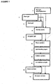
- Example 1 illustrates one possible way for carrying out the invention. This is also shown in Figure 1 .
- Electrophoresis of the macromolecular complexes to be analyzed is performed under non-denaturing (native) conditions using a buffer system that maintains the native protein conformation, subunit interaction, and biological activity [Maurer, H. (1971); Laemmli, U. K. (1970)].
- native electrophoresis proteins are separated based on their charge to mass ratios. All gel electrophoresis steps are performed using equipment available at Invitrogen (Carlsbad, USA).
- a polyacrylamid separating gel (NuPAGE Novex® Tris-Acetate Gel, range 3-8%, 1 mm thick) is running in a (XCell SureLock) Mini-Cell at a constant Voltage of 150 V for 2.30 h with a current of 18 mA/gel (start) to 7 mA/gel (end).
- As a running buffer 100 ml 10X Tris-Glycine Native Running Buffer with 900 ml deionized water is used. In multiple lanes the same sample, here a macromolecular protein, is loaded to the gel to allow further identification (see step 3, below).
- one lane is loaded with a marker (HMW electrophoresis calibration kit 17-0445, Amersham Pharmacia Biotech, Piscataway, USA) which is well characterized by the manufacturer in terms of defined mass/charge ratios forming specific bands on the gel.
- a marker HMW electrophoresis calibration kit 17-0445, Amersham Pharmacia Biotech, Piscataway, USA
- the gel is cut in half. One part is preserved in a wet tissue and stored for further usage in a fridge at 4°C. The other part is silver stained, based on the chemical reduction of silver ions to metallic silver on a protein band using SilverXpress® Silver Staining Kit available at Invitrogen (Carlsbad, USA).
- the stained part of the gel is positioned adjacent to the non-stained gel and carefully aligned at the top. By extrapolating the position of the stained bands to the non-stained gel the areas of interest, respectively the bands carrying macromolecules are located. For comparison and orientation additional information can be obtained from the marker lane showing well defined bands with well defined mass/charge ratios.
- the gel can be pricked with a forceps at the bands of interest to enlarge the surface at these positions.
- the top layer of the gel is disrupted and deeper gel layers with a high concentration of macromolecules are exposed to the surface of the gel.
- the depth of the disruption is half of the grids height, typically 0.5 mm
- the lateral size is the diameter of the grid, typically 3 mm.
- a copper grid covered with carbon film (commercially available at Plano GmbH, Wetzlar, Germany), respectively with a holey carbon film (commercially available at Quantifoil Micro Tools GmbH, Jena, Germany or Pacific GridTech, San Diego, USA) is placed centrally on specific, in step 3 identified bands with a forceps.
- the grid is handled carefully at the border to prevent any disruption of the carbon film and oriented in parallel to the gel's surface, and parallel to the direction to the direction of the separation force.
- Figure 2 shows schematically, how the grid is oriented on the gel.
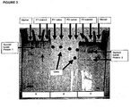
- Immobilization of the macromolecular complexes, such as the ones shown in Figure 4 , on the electron microscopic carrier is carried out by two different techniques - negative staining and cryo-fixation [Harris, J. R. et al. (1991); Dubochet, J. et al. (1982)].
- a washing step is performed with two drops of deionized water and subsequently contrast enhancement with two drops of heavy metal.
- a second preparation technique - cryo fixation the sample is rapidly frozen. After removing excess fluid by blotting, a thin layer of solution on the electron microscopic grid is obtained. The grid is then plunged into liquid ethane.
- the aqueous suspension converts to a vitreous phase directly, bypassing the crystalline ice.
- the frozen grid will have a thin aqueous layer with macromolecules embedded in an almost natural frozen hydrated environment. After freezing, grids can be kept for a long time at liquid-nitrogen temperatures. These structurally preserved frozen-hydrated samples are then imaged in an electron microscope at liquid-nitrogen or liquid-helium temperatures.
- Example 2 in connection with Figures 5 and 6 illustrates one possibility how the method of the present invention can be utilized in an automated process which is contolled by a robot.
- the method of the invention can be used for an apparatus performing in an automated way.
- a gel loading device (1) is connected to a computer controlling unit (12) and transports gels (2) located at gel carriers (8) serially to the grid blotting robot (6).
- a single, actually processed gel is placed on a gel scanner (9) inside the grid blotting robot (6).
- After moving the gel to its location the gel is scanned by a gel scanner (9) automatically driven by the computer controlling unit (12).
- This procedure is shown in detail in figure 6 where the scanning device (2) is attached to the computer control (4) and delivers an image of the electrophoretic matrix (1).
- the bands of interest can be identified and located by transferring the coordinates of the image of the gel to the coordinates of the positioning system (3), respectively the positioning system (5) shown in figure 5 .
- the positioning system (5) is used to move the gel roughening tool (4b) which is formed like a forceps over the band position investigated by the method.
- the gel is roughened by the gel roughening tool (4b) in a way that deeper layers of the gel are exposed.
- the positioning system (5) moves the grid clamping device (4) over the grid storage unit (7) and picks one grid. Afterwards the grid is moved by the positioning system (5) in a computer controlled way to the selected position on the gel, respectively the band of interest and is gently placed parallel to the surface of the gel and as described in the method of the present invention.
- a drop of running buffer solution is added to the grid located on the gel using a microfluidic device (3) directed by the positioning system (5) which is controlled by the computer controlling unit (12).
- the grid is picked by the grid clamping device, moved by the positioning system (5) and transferred to a grid carrier (11).
- a fixation device (13) where the grid is further processed by negative staining or cryo-fixation of the sample.
- the fixated grid is moved to a storage device (14) for short or long-term storage of the sample.
Landscapes
- Chemical & Material Sciences (AREA)
- Life Sciences & Earth Sciences (AREA)
- Health & Medical Sciences (AREA)
- Molecular Biology (AREA)
- Biochemistry (AREA)
- Organic Chemistry (AREA)
- General Health & Medical Sciences (AREA)
- Analytical Chemistry (AREA)
- Pathology (AREA)
- Chemical Kinetics & Catalysis (AREA)
- General Physics & Mathematics (AREA)
- Immunology (AREA)
- Electrochemistry (AREA)
- Biophysics (AREA)
- Genetics & Genomics (AREA)
- Medicinal Chemistry (AREA)
- Proteomics, Peptides & Aminoacids (AREA)
- Physics & Mathematics (AREA)
- Investigating Or Analysing Biological Materials (AREA)
- Analysing Materials By The Use Of Radiation (AREA)
- Sampling And Sample Adjustment (AREA)
- Peptides Or Proteins (AREA)
- Investigating Or Analysing Materials By The Use Of Chemical Reactions (AREA)
- Measuring Or Testing Involving Enzymes Or Micro-Organisms (AREA)
- Apparatus Associated With Microorganisms And Enzymes (AREA)
Claims (22)
- Procédé de détection et/ou d'analyse de la structure de complexes macromoléculaires et/ou de macromolécules comprenant les étapes consistant à :(a) purifier ou séparer lesdits complexes macromoléculaires et/ou lesdites macromolécules à partir d'un échantillon contenant lesdits complexes macromoléculaires et/ou lesdites macromolécules en appliquant dans une matrice poreuse une force de séparation dans une première dimension (axe X) ;(b) transférer dans une deuxième dimension (axe Z) par des forces d'adsorption les complexes macromoléculaires et/ou les macromolécules purifié(e)s ou séparé(e)s dans l'étape (a) depuis la matrice poreuse vers un support, où ledit support est une grille de microscope électronique et est en contact avec la surface de la matrice poreuse et est positionné parallèlement à la surface de ladite matrice et parallèlement à la direction de la force de séparation appliquée dans l'étape (a) ;(c) immobiliser les complexes macromoléculaires et/ou les macromolécules sur ledit support après le transfert de l'étape (b) ; et(d) évaluer la structure des complexes macromoléculaires et/ou des macromolécules sur ledit support après l'immobilisation de l'étape (c).
- Procédé permettant d'analyser si un sujet est affecté par une maladie ou prédisposé à développer une maladie, dans lequel ladite maladie est en corrélation avec la présence ou l'absence de complexes protéiques, et/ou de complexes viraux, et/ou de complexes bactériens et/ou de complexes fongiques, et/ou de complexes à prion comprenant les étapes consistant à(a) évaluer la présence et facultativement la structure desdits complexes protéiques, et/ou complexes viraux et/ou complexes bactériens et/ou complexes fongiques et/ou complexes à prion(aa) en purifiant ou en séparant lesdits complexes protéiques, et/ou complexes viraux, et/ou complexes bactériens, et/ou complexes fongiques, et/ou complexes à prion à partir d'un échantillon contenant d'une façon putative lesdits complexes protéiques, et/ou complexes viraux, et/ou complexes bactériens, et/ou complexes fongiques, et/ou complexes à prion en appliquant dans une matrice poreuse une force de séparation dans une première dimension (axe X) ;(ab) en transférant dans une deuxième dimension (axe Z) par des forces d'adsorption les complexes protéiques, et/ou complexes viraux, et/ou complexes bactériens, et/ou complexes fongiques, et/ou complexes à prion purifiés ou séparés dans l'étape (aa) depuis la matrice poreuse vers un support, où ledit support est une grille de microscope électronique et est en contact avec la surface de la matrice poreuse et est positionné parallèlement à la surface de ladite matrice et parallèlement à la direction de la force de séparation appliquée dans l'étape (aa) ;(ac) en immobilisant les complexes protéiques, et/ou complexes viraux, et/ou complexes bactériens, et/ou complexes fongiques, et/ou complexes à prion sur ledit support après l'étape de transfert de l'étape 2(ab) ; et(b) en mettant en corrélation la présence ou l'absence ou la structure des complexes protéiques, et/ou complexes viraux, et/ou complexes bactériens, et/ou complexes fongiques, et/ou complexes à prion sur ledit support avec l'affection dudit sujet par une maladie ou sa prédisposition à développer une maladie.
- Procédé selon la revendication 2, dans lequel ledit sujet est un humain.
- Procédé selon l'une quelconque des revendications 1 à 3, comprenant en outre après l'étape 1(a) ou l'étape 2(aa) et avant l'étape 1(b) ou l'étape (2ab) l'étape (a'), dans laquelle une seconde force de séparation est appliquée dans une troisième dimension (axe Y) sur les complexes macromoléculaires et/ou sur les macromolécules purifié(e)s ou séparé(e)s dans l'étape 1(a) ou sur les complexes protéiques, et/ou complexes viraux, et/ou complexes bactériens, et/ou complexes fongiques, et/ou complexes à prion purifiés ou séparés dans l'étape 2(aa).
- Procédé selon la revendication 4, dans lequel le vecteur de la seconde force de séparation décrit un angle dans la troisième dimension par rapport au vecteur de la force de séparation de l'étape 1(a) ou de l'étape 2(aa) dans la gamme entre 1 degré et 180 degrés.
- Procédé selon l'une quelconque des revendications 1 à 5, dans lequel ladite force de séparation est produite par un champ électrique ou par la gravité.
- Procédé selon l'une quelconque des revendications 1 à 6, dans lequel après l'étape 1(a) ou l'étape 2(aa) et avant l'étape 1(b) ou l'étape 2(ab) la matrice poreuse est colorée et/ou numérisée.
- Procédé selon l'une quelconque des revendications 1 à 7, dans lequel ladite surface de la matrice est rugueuse.
- Procédé selon l'une quelconque des revendications 1 à 8, dans lequel ledit support qui est en contact avec la surface de la matrice poreuse est entourée d'un milieu tampon.
- Procédé selon l'une quelconque des revendications 1 à 9, dans lequel le transfert dans l'étape 1(b) ou l'étape 2(ab) est accéléré et le rendement de l'échantillon transféré est augmenté en appliquant en plus un champ électrique dans lequel le vecteur dudit champ électrique est orienté dans la deuxième dimension (axe Z).
- Procédé selon l'une quelconque des revendications 1 à 10, dans lequel ladite matrice poreuse est un gel ou un nanocomposite.
- Procédé selon la revendication 11, dans lequel ledit gel est un gel de polyacrylamide ou un gel d'agarose.
- Procédé selon la revendication 11 ou 12, dans lequel ledit gel est un gel à gradient.
- Procédé selon la revendication 13, dans lequel ledit gradient est dans la gamme allant de 0,01 % (p/v) à 50 % (p/v), de préférence dans la gamme allant de 0,5 % (p/v) à 40 % (p/v), et de manière davantage préférée dans la gamme allant de 1 % (p/v) à 8 % (p/v).
- Procédé selon l'une quelconque des revendications 1 à 14, dans lequel ladite grille de microscope électronique est recouverte d'une couche transmettant des électrons ou d'une feuille perforée.
- Procédé selon l'une quelconque des revendications 1 et 4 à 15, dans lequel lesdits complexes macromoléculaires sont choisis dans le groupe constitué par des complexes protéiques, des particules virales, des eubactéries, des archéobactéries, des composés chimiques organiques et non organiques.
- Procédé selon l'une quelconque des revendications 1 à 16, dans lequel lesdits complexes protéiques sont des complexes de protéines natives.
- Procédé selon l'une quelconque des revendications 1 à 17, dans lequel ladite immobilisation dans l'étape 1(c) ou l'étape 2(ac) est une cryofixation.
- Procédé selon l'une quelconque des revendications 1 à 17, dans lequel ladite immobilisation dans l'étape 1(c) ou l'étape 2(ac) est une coloration négative avec des sels d'atomes lourds.
- Procédé selon l'une quelconque des revendications 1 à 19, dans lequel ladite évaluation de la structure des complexes macromoléculaires et/ou des macromolécules dans l'étape 1(d) ou ladite évaluation de la présence et facultativement de la structure desdits complexes protéiques, et/ou complexes viraux et/ou complexes bactériens et/ou complexes fongiques et/ou complexes à prion dans l'étape 2(a) est effectuée par microscopie électronique.
- Procédé selon l'une quelconque des revendications 1 à 20, dans lequel ledit procédé est un procédé de criblage à haut débit.
- Dispositif ou robot permettant de détecter et/ou d'analyser la structure de complexes macromoléculaires et/ou de macromolécules comme cela est défini dans l'une quelconque des revendications 1 et 4 à 21 ou permettant d'analyser si un sujet est affecté par une maladie ou prédisposé à développer une maladie comme cela est défini dans l'une quelconque des revendications 2 à 15 et 17 à 21, dans lequel ledit dispositif comprend :(a) un dispositif chargeur de gel (1)(b) un transporteur de gel(c) un robot de transfert sur grille (6) avec un dispositif de serrage de grille (4), un système de positionnement (5), un numériseur de gel (9) et facultativement un outil pour rendre le gel rugueux (4b)(d) un dispositif de fixation (13)(e) un dispositif de stockage (14) ; et(f) une unité de contrôle informatique (12).
Priority Applications (6)
| Application Number | Priority Date | Filing Date | Title |
|---|---|---|---|
| DE602004011900T DE602004011900T2 (de) | 2004-04-28 | 2004-04-28 | Verfahren zum Nachweis und zur Analyse von makromolekularen Komplexen |
| AT04010121T ATE386931T1 (de) | 2004-04-28 | 2004-04-28 | Verfahren zum nachweis und zur analyse von makromolekularen komplexen |
| EP04010121A EP1591783B1 (fr) | 2004-04-28 | 2004-04-28 | Méthode pour la détection et l'analyse des complexes macromoléculaires |
| JP2007509973A JP5054514B2 (ja) | 2004-04-28 | 2005-04-28 | 巨大分子複合体の検出および分析の方法 |
| US11/587,837 US20080213748A1 (en) | 2004-04-28 | 2005-04-28 | Method for Detection and Analysis of Macromolecular Complexes |
| PCT/EP2005/004600 WO2005106447A1 (fr) | 2004-04-28 | 2005-04-28 | Procede pour detecter et analyser des complexes macromoleculaires |
Applications Claiming Priority (1)
| Application Number | Priority Date | Filing Date | Title |
|---|---|---|---|
| EP04010121A EP1591783B1 (fr) | 2004-04-28 | 2004-04-28 | Méthode pour la détection et l'analyse des complexes macromoléculaires |
Publications (2)
| Publication Number | Publication Date |
|---|---|
| EP1591783A1 EP1591783A1 (fr) | 2005-11-02 |
| EP1591783B1 true EP1591783B1 (fr) | 2008-02-20 |
Family
ID=34924774
Family Applications (1)
| Application Number | Title | Priority Date | Filing Date |
|---|---|---|---|
| EP04010121A Expired - Lifetime EP1591783B1 (fr) | 2004-04-28 | 2004-04-28 | Méthode pour la détection et l'analyse des complexes macromoléculaires |
Country Status (6)
| Country | Link |
|---|---|
| US (1) | US20080213748A1 (fr) |
| EP (1) | EP1591783B1 (fr) |
| JP (1) | JP5054514B2 (fr) |
| AT (1) | ATE386931T1 (fr) |
| DE (1) | DE602004011900T2 (fr) |
| WO (1) | WO2005106447A1 (fr) |
Families Citing this family (2)
| Publication number | Priority date | Publication date | Assignee | Title |
|---|---|---|---|---|
| CN107014652B (zh) * | 2017-04-14 | 2023-03-24 | 广西大学 | 一种用于透射电镜的环形载网与截面样品对粘的装置 |
| CN112920252B (zh) * | 2021-01-22 | 2022-07-05 | 湘雅生物医药(湖州)有限公司 | 一种多肽分级分离的膜分离设备 |
Family Cites Families (8)
| Publication number | Priority date | Publication date | Assignee | Title |
|---|---|---|---|---|
| US5858781A (en) * | 1994-05-13 | 1999-01-12 | Matyas; John R. | Method of tissue transfer and retrieval |
| JP3999292B2 (ja) * | 1996-09-04 | 2007-10-31 | 富士フイルム株式会社 | 表面プラズモンセンサー |
| JP2002257721A (ja) * | 2000-12-28 | 2002-09-11 | Mitsubishi Chemicals Corp | 検体分析方法及び検体分析装置 |
| US20030044843A1 (en) * | 2001-01-09 | 2003-03-06 | Mitsubishi Pharma Corporation | Novel proteome analysis method and devices therefor |
| AUPR378001A0 (en) * | 2001-03-16 | 2001-04-12 | Proteome Systems Ltd | Protein chip |
| WO2002090966A1 (fr) * | 2001-05-10 | 2002-11-14 | Large Scale Proteomics Corporation | Appareil automatique permettant de separer un echantillon biologique d'un gel d'electrophorese bidimensionnel |
| US6555334B2 (en) * | 2001-09-10 | 2003-04-29 | The United States Of America As Represented By The Secretary Of The Army | Free floating cryostat sections for use in light and electron microscopy and method |
| AU2003272924B2 (en) * | 2002-10-04 | 2008-05-15 | Protosera Inc. | Plate for mass spectrometry, process for preparing the same and use thereof |
-
2004
- 2004-04-28 EP EP04010121A patent/EP1591783B1/fr not_active Expired - Lifetime
- 2004-04-28 DE DE602004011900T patent/DE602004011900T2/de not_active Expired - Lifetime
- 2004-04-28 AT AT04010121T patent/ATE386931T1/de not_active IP Right Cessation
-
2005
- 2005-04-28 WO PCT/EP2005/004600 patent/WO2005106447A1/fr not_active Ceased
- 2005-04-28 JP JP2007509973A patent/JP5054514B2/ja not_active Expired - Fee Related
- 2005-04-28 US US11/587,837 patent/US20080213748A1/en not_active Abandoned
Also Published As
| Publication number | Publication date |
|---|---|
| JP2007534950A (ja) | 2007-11-29 |
| WO2005106447A1 (fr) | 2005-11-10 |
| EP1591783A1 (fr) | 2005-11-02 |
| DE602004011900T2 (de) | 2009-02-26 |
| JP5054514B2 (ja) | 2012-10-24 |
| DE602004011900D1 (de) | 2008-04-03 |
| US20080213748A1 (en) | 2008-09-04 |
| ATE386931T1 (de) | 2008-03-15 |
Similar Documents
| Publication | Publication Date | Title |
|---|---|---|
| US7939270B2 (en) | Delivery of molecules to a lipid bilayer | |
| CN106459118B (zh) | 聚糖样品制备 | |
| US11715633B2 (en) | Multiplexed inductive ionization systems and methods | |
| JP2009520989A (ja) | 分析法のためのナノ多孔性基材 | |
| WO2007136386A2 (fr) | Préparation d'échantillons sur puce à base de gouttelettes destinée à la spectrométrie de masse | |
| JP2004500567A (ja) | タンパク質分離および提示 | |
| CN101111762A (zh) | 通过双向电泳同时分离生物分子的方法和仪器 | |
| EP2294395A1 (fr) | Procédés et systèmes pour la séparation et l'analyse de substances à analyser à l'aide de ffe | |
| US6676819B1 (en) | Methods and apparatus for automatic on-line multi-dimensional electrophoresis | |
| US20060198765A1 (en) | Method and device for sample preparation | |
| CA2505255C (fr) | Dispositif et methode de separation pour des echantillons de biomolecules | |
| JPWO2011162290A1 (ja) | 生体関連物質の捕捉装置および生体関連物質の採取システム | |
| KR20160110806A (ko) | Ffpe 조직에서 핵산의 분리 방법 | |
| Rekhter et al. | Molecular analysis of complex tissues is facilitated by laser capture microdissection: critical role of upstream tissue processing | |
| EP1591783B1 (fr) | Méthode pour la détection et l'analyse des complexes macromoléculaires | |
| US20150299761A1 (en) | Substrates and Methods for Preparing Samples for Mass Spectrometry | |
| US20090286305A1 (en) | Method for non-destructive macromolecule extraction from biological samples on slide | |
| Hayama et al. | Recent development and trends in sample extraction and preparation for mass spectrometric analysis of nucleotides, nucleosides, and proteins | |
| JP2008544232A (ja) | ゲルに複数のウェルを形成する方法及び装置 | |
| Tayade et al. | Laser capture microdissection | |
| WO2003016896A1 (fr) | Procede et dispositif d'electrophorese et de transfert | |
| US20160313311A1 (en) | Label-free detection of macromolecules binding to compound libraries | |
| US7250097B2 (en) | Device for sequential protein transfer from a gel | |
| JP2008544233A (ja) | ゲル中の被分析物に試薬を加える方法及び装置 | |
| Wobig | Methods in metallomics, proteomics, and toxicology: Development and applications of laser ablation inductively coupled plasma mass spectrometry and native SDS-PAGE |
Legal Events
| Date | Code | Title | Description |
|---|---|---|---|
| PUAI | Public reference made under article 153(3) epc to a published international application that has entered the european phase |
Free format text: ORIGINAL CODE: 0009012 |
|
| 17P | Request for examination filed |
Effective date: 20050125 |
|
| AK | Designated contracting states |
Kind code of ref document: A1 Designated state(s): AT BE BG CH CY CZ DE DK EE ES FI FR GB GR HU IE IT LI LU MC NL PL PT RO SE SI SK TR |
|
| AX | Request for extension of the european patent |
Extension state: AL HR LT LV MK |
|
| AKX | Designation fees paid |
Designated state(s): AT BE BG CH CY CZ DE DK EE ES FI FR GB GR HU IE IT LI LU MC NL PL PT RO SE SI SK TR |
|
| 17Q | First examination report despatched |
Effective date: 20060330 |
|
| GRAP | Despatch of communication of intention to grant a patent |
Free format text: ORIGINAL CODE: EPIDOSNIGR1 |
|
| RIC1 | Information provided on ipc code assigned before grant |
Ipc: G01N 1/42 20060101ALN20070727BHEP Ipc: G01N 27/447 20060101AFI20070727BHEP Ipc: G01N 33/68 20060101ALN20070727BHEP Ipc: C07K 1/04 20060101ALI20070727BHEP |
|
| GRAS | Grant fee paid |
Free format text: ORIGINAL CODE: EPIDOSNIGR3 |
|
| GRAA | (expected) grant |
Free format text: ORIGINAL CODE: 0009210 |
|
| AK | Designated contracting states |
Kind code of ref document: B1 Designated state(s): AT BE BG CH CY CZ DE DK EE ES FI FR GB GR HU IE IT LI LU MC NL PL PT RO SE SI SK TR |
|
| REG | Reference to a national code |
Ref country code: GB Ref legal event code: FG4D |
|
| REG | Reference to a national code |
Ref country code: CH Ref legal event code: EP |
|
| REG | Reference to a national code |
Ref country code: IE Ref legal event code: FG4D |
|
| REF | Corresponds to: |
Ref document number: 602004011900 Country of ref document: DE Date of ref document: 20080403 Kind code of ref document: P |
|
| REG | Reference to a national code |
Ref country code: CH Ref legal event code: NV Representative=s name: VOSSIUS & PARTNER |
|
| PG25 | Lapsed in a contracting state [announced via postgrant information from national office to epo] |
Ref country code: FI Free format text: LAPSE BECAUSE OF FAILURE TO SUBMIT A TRANSLATION OF THE DESCRIPTION OR TO PAY THE FEE WITHIN THE PRESCRIBED TIME-LIMIT Effective date: 20080220 Ref country code: ES Free format text: LAPSE BECAUSE OF FAILURE TO SUBMIT A TRANSLATION OF THE DESCRIPTION OR TO PAY THE FEE WITHIN THE PRESCRIBED TIME-LIMIT Effective date: 20080531 |
|
| NLV1 | Nl: lapsed or annulled due to failure to fulfill the requirements of art. 29p and 29m of the patents act | ||
| PG25 | Lapsed in a contracting state [announced via postgrant information from national office to epo] |
Ref country code: AT Free format text: LAPSE BECAUSE OF FAILURE TO SUBMIT A TRANSLATION OF THE DESCRIPTION OR TO PAY THE FEE WITHIN THE PRESCRIBED TIME-LIMIT Effective date: 20080220 |
|
| PG25 | Lapsed in a contracting state [announced via postgrant information from national office to epo] |
Ref country code: PL Free format text: LAPSE BECAUSE OF FAILURE TO SUBMIT A TRANSLATION OF THE DESCRIPTION OR TO PAY THE FEE WITHIN THE PRESCRIBED TIME-LIMIT Effective date: 20080220 Ref country code: SI Free format text: LAPSE BECAUSE OF FAILURE TO SUBMIT A TRANSLATION OF THE DESCRIPTION OR TO PAY THE FEE WITHIN THE PRESCRIBED TIME-LIMIT Effective date: 20080220 Ref country code: BE Free format text: LAPSE BECAUSE OF FAILURE TO SUBMIT A TRANSLATION OF THE DESCRIPTION OR TO PAY THE FEE WITHIN THE PRESCRIBED TIME-LIMIT Effective date: 20080220 |
|
| ET | Fr: translation filed | ||
| PG25 | Lapsed in a contracting state [announced via postgrant information from national office to epo] |
Ref country code: SK Free format text: LAPSE BECAUSE OF FAILURE TO SUBMIT A TRANSLATION OF THE DESCRIPTION OR TO PAY THE FEE WITHIN THE PRESCRIBED TIME-LIMIT Effective date: 20080220 Ref country code: DK Free format text: LAPSE BECAUSE OF FAILURE TO SUBMIT A TRANSLATION OF THE DESCRIPTION OR TO PAY THE FEE WITHIN THE PRESCRIBED TIME-LIMIT Effective date: 20080220 Ref country code: CZ Free format text: LAPSE BECAUSE OF FAILURE TO SUBMIT A TRANSLATION OF THE DESCRIPTION OR TO PAY THE FEE WITHIN THE PRESCRIBED TIME-LIMIT Effective date: 20080220 Ref country code: PT Free format text: LAPSE BECAUSE OF FAILURE TO SUBMIT A TRANSLATION OF THE DESCRIPTION OR TO PAY THE FEE WITHIN THE PRESCRIBED TIME-LIMIT Effective date: 20080721 Ref country code: NL Free format text: LAPSE BECAUSE OF FAILURE TO SUBMIT A TRANSLATION OF THE DESCRIPTION OR TO PAY THE FEE WITHIN THE PRESCRIBED TIME-LIMIT Effective date: 20080220 Ref country code: SE Free format text: LAPSE BECAUSE OF FAILURE TO SUBMIT A TRANSLATION OF THE DESCRIPTION OR TO PAY THE FEE WITHIN THE PRESCRIBED TIME-LIMIT Effective date: 20080520 |
|
| PG25 | Lapsed in a contracting state [announced via postgrant information from national office to epo] |
Ref country code: RO Free format text: LAPSE BECAUSE OF FAILURE TO SUBMIT A TRANSLATION OF THE DESCRIPTION OR TO PAY THE FEE WITHIN THE PRESCRIBED TIME-LIMIT Effective date: 20080220 Ref country code: MC Free format text: LAPSE BECAUSE OF NON-PAYMENT OF DUE FEES Effective date: 20080430 |
|
| PLBE | No opposition filed within time limit |
Free format text: ORIGINAL CODE: 0009261 |
|
| STAA | Information on the status of an ep patent application or granted ep patent |
Free format text: STATUS: NO OPPOSITION FILED WITHIN TIME LIMIT |
|
| 26N | No opposition filed |
Effective date: 20081121 |
|
| PG25 | Lapsed in a contracting state [announced via postgrant information from national office to epo] |
Ref country code: EE Free format text: LAPSE BECAUSE OF FAILURE TO SUBMIT A TRANSLATION OF THE DESCRIPTION OR TO PAY THE FEE WITHIN THE PRESCRIBED TIME-LIMIT Effective date: 20080220 |
|
| PG25 | Lapsed in a contracting state [announced via postgrant information from national office to epo] |
Ref country code: BG Free format text: LAPSE BECAUSE OF FAILURE TO SUBMIT A TRANSLATION OF THE DESCRIPTION OR TO PAY THE FEE WITHIN THE PRESCRIBED TIME-LIMIT Effective date: 20080520 Ref country code: IE Free format text: LAPSE BECAUSE OF NON-PAYMENT OF DUE FEES Effective date: 20080428 |
|
| PG25 | Lapsed in a contracting state [announced via postgrant information from national office to epo] |
Ref country code: CY Free format text: LAPSE BECAUSE OF FAILURE TO SUBMIT A TRANSLATION OF THE DESCRIPTION OR TO PAY THE FEE WITHIN THE PRESCRIBED TIME-LIMIT Effective date: 20080220 |
|
| PG25 | Lapsed in a contracting state [announced via postgrant information from national office to epo] |
Ref country code: IT Free format text: LAPSE BECAUSE OF FAILURE TO SUBMIT A TRANSLATION OF THE DESCRIPTION OR TO PAY THE FEE WITHIN THE PRESCRIBED TIME-LIMIT Effective date: 20080220 |
|
| PG25 | Lapsed in a contracting state [announced via postgrant information from national office to epo] |
Ref country code: HU Free format text: LAPSE BECAUSE OF FAILURE TO SUBMIT A TRANSLATION OF THE DESCRIPTION OR TO PAY THE FEE WITHIN THE PRESCRIBED TIME-LIMIT Effective date: 20080821 Ref country code: LU Free format text: LAPSE BECAUSE OF NON-PAYMENT OF DUE FEES Effective date: 20080428 |
|
| PG25 | Lapsed in a contracting state [announced via postgrant information from national office to epo] |
Ref country code: TR Free format text: LAPSE BECAUSE OF FAILURE TO SUBMIT A TRANSLATION OF THE DESCRIPTION OR TO PAY THE FEE WITHIN THE PRESCRIBED TIME-LIMIT Effective date: 20080220 |
|
| PG25 | Lapsed in a contracting state [announced via postgrant information from national office to epo] |
Ref country code: GR Free format text: LAPSE BECAUSE OF FAILURE TO SUBMIT A TRANSLATION OF THE DESCRIPTION OR TO PAY THE FEE WITHIN THE PRESCRIBED TIME-LIMIT Effective date: 20080521 |
|
| PGFP | Annual fee paid to national office [announced via postgrant information from national office to epo] |
Ref country code: CH Payment date: 20120516 Year of fee payment: 9 Ref country code: DE Payment date: 20120531 Year of fee payment: 9 |
|
| PGFP | Annual fee paid to national office [announced via postgrant information from national office to epo] |
Ref country code: GB Payment date: 20120430 Year of fee payment: 9 Ref country code: FR Payment date: 20120510 Year of fee payment: 9 |
|
| REG | Reference to a national code |
Ref country code: CH Ref legal event code: PL |
|
| GBPC | Gb: european patent ceased through non-payment of renewal fee |
Effective date: 20130428 |
|
| PG25 | Lapsed in a contracting state [announced via postgrant information from national office to epo] |
Ref country code: DE Free format text: LAPSE BECAUSE OF NON-PAYMENT OF DUE FEES Effective date: 20131101 Ref country code: LI Free format text: LAPSE BECAUSE OF NON-PAYMENT OF DUE FEES Effective date: 20130430 Ref country code: GB Free format text: LAPSE BECAUSE OF NON-PAYMENT OF DUE FEES Effective date: 20130428 Ref country code: CH Free format text: LAPSE BECAUSE OF NON-PAYMENT OF DUE FEES Effective date: 20130430 |
|
| REG | Reference to a national code |
Ref country code: FR Ref legal event code: ST Effective date: 20131231 |
|
| REG | Reference to a national code |
Ref country code: DE Ref legal event code: R119 Ref document number: 602004011900 Country of ref document: DE Effective date: 20131101 |
|
| PG25 | Lapsed in a contracting state [announced via postgrant information from national office to epo] |
Ref country code: FR Free format text: LAPSE BECAUSE OF NON-PAYMENT OF DUE FEES Effective date: 20130430 |