EP1591703B1 - Bursting disc assembly - Google Patents
Bursting disc assembly Download PDFInfo
- Publication number
- EP1591703B1 EP1591703B1 EP05015717A EP05015717A EP1591703B1 EP 1591703 B1 EP1591703 B1 EP 1591703B1 EP 05015717 A EP05015717 A EP 05015717A EP 05015717 A EP05015717 A EP 05015717A EP 1591703 B1 EP1591703 B1 EP 1591703B1
- Authority
- EP
- European Patent Office
- Prior art keywords
- support
- disc
- flange
- support ring
- projection
- Prior art date
- Legal status (The legal status is an assumption and is not a legal conclusion. Google has not performed a legal analysis and makes no representation as to the accuracy of the status listed.)
- Expired - Lifetime
Links
- 230000009172 bursting Effects 0.000 title claims description 14
- 230000002093 peripheral effect Effects 0.000 claims description 10
- 230000013011 mating Effects 0.000 claims description 5
- 230000007704 transition Effects 0.000 description 26
- 239000007788 liquid Substances 0.000 description 7
- 239000007789 gas Substances 0.000 description 6
- 241000219793 Trifolium Species 0.000 description 5
- 230000000712 assembly Effects 0.000 description 5
- 238000000429 assembly Methods 0.000 description 5
- 230000000977 initiatory effect Effects 0.000 description 4
- 238000000034 method Methods 0.000 description 3
- 229910000851 Alloy steel Inorganic materials 0.000 description 1
- 229910000831 Steel Inorganic materials 0.000 description 1
- 238000005452 bending Methods 0.000 description 1
- 230000015572 biosynthetic process Effects 0.000 description 1
- 238000007796 conventional method Methods 0.000 description 1
- 238000013467 fragmentation Methods 0.000 description 1
- 238000006062 fragmentation reaction Methods 0.000 description 1
- 239000000463 material Substances 0.000 description 1
- 230000007246 mechanism Effects 0.000 description 1
- 239000012528 membrane Substances 0.000 description 1
- 239000002184 metal Substances 0.000 description 1
- 239000007769 metal material Substances 0.000 description 1
- 238000003801 milling Methods 0.000 description 1
- 238000012986 modification Methods 0.000 description 1
- 230000004048 modification Effects 0.000 description 1
- 239000010959 steel Substances 0.000 description 1
- 230000035899 viability Effects 0.000 description 1
Images

Classifications
-
- F—MECHANICAL ENGINEERING; LIGHTING; HEATING; WEAPONS; BLASTING
- F16—ENGINEERING ELEMENTS AND UNITS; GENERAL MEASURES FOR PRODUCING AND MAINTAINING EFFECTIVE FUNCTIONING OF MACHINES OR INSTALLATIONS; THERMAL INSULATION IN GENERAL
- F16K—VALVES; TAPS; COCKS; ACTUATING-FLOATS; DEVICES FOR VENTING OR AERATING
- F16K17/00—Safety valves; Equalising valves, e.g. pressure relief valves
- F16K17/02—Safety valves; Equalising valves, e.g. pressure relief valves opening on surplus pressure on one side; closing on insufficient pressure on one side
- F16K17/14—Safety valves; Equalising valves, e.g. pressure relief valves opening on surplus pressure on one side; closing on insufficient pressure on one side with fracturing member
- F16K17/16—Safety valves; Equalising valves, e.g. pressure relief valves opening on surplus pressure on one side; closing on insufficient pressure on one side with fracturing member with fracturing diaphragm ; Rupture discs
-
- F—MECHANICAL ENGINEERING; LIGHTING; HEATING; WEAPONS; BLASTING
- F16—ENGINEERING ELEMENTS AND UNITS; GENERAL MEASURES FOR PRODUCING AND MAINTAINING EFFECTIVE FUNCTIONING OF MACHINES OR INSTALLATIONS; THERMAL INSULATION IN GENERAL
- F16K—VALVES; TAPS; COCKS; ACTUATING-FLOATS; DEVICES FOR VENTING OR AERATING
- F16K17/00—Safety valves; Equalising valves, e.g. pressure relief valves
- F16K17/02—Safety valves; Equalising valves, e.g. pressure relief valves opening on surplus pressure on one side; closing on insufficient pressure on one side
- F16K17/14—Safety valves; Equalising valves, e.g. pressure relief valves opening on surplus pressure on one side; closing on insufficient pressure on one side with fracturing member
- F16K17/16—Safety valves; Equalising valves, e.g. pressure relief valves opening on surplus pressure on one side; closing on insufficient pressure on one side with fracturing member with fracturing diaphragm ; Rupture discs
- F16K17/1606—Safety valves; Equalising valves, e.g. pressure relief valves opening on surplus pressure on one side; closing on insufficient pressure on one side with fracturing member with fracturing diaphragm ; Rupture discs of the reverse-buckling-type
- F16K17/1613—Safety valves; Equalising valves, e.g. pressure relief valves opening on surplus pressure on one side; closing on insufficient pressure on one side with fracturing member with fracturing diaphragm ; Rupture discs of the reverse-buckling-type with additional cutting means
-
- Y—GENERAL TAGGING OF NEW TECHNOLOGICAL DEVELOPMENTS; GENERAL TAGGING OF CROSS-SECTIONAL TECHNOLOGIES SPANNING OVER SEVERAL SECTIONS OF THE IPC; TECHNICAL SUBJECTS COVERED BY FORMER USPC CROSS-REFERENCE ART COLLECTIONS [XRACs] AND DIGESTS
- Y10—TECHNICAL SUBJECTS COVERED BY FORMER USPC
- Y10T—TECHNICAL SUBJECTS COVERED BY FORMER US CLASSIFICATION
- Y10T137/00—Fluid handling
- Y10T137/1624—Destructible or deformable element controlled
- Y10T137/1632—Destructible element
- Y10T137/1692—Rupture disc
- Y10T137/1714—Direct pressure causes disc to burst
- Y10T137/1729—Dome shape
- Y10T137/1737—Reverse buckling
-
- Y—GENERAL TAGGING OF NEW TECHNOLOGICAL DEVELOPMENTS; GENERAL TAGGING OF CROSS-SECTIONAL TECHNOLOGIES SPANNING OVER SEVERAL SECTIONS OF THE IPC; TECHNICAL SUBJECTS COVERED BY FORMER USPC CROSS-REFERENCE ART COLLECTIONS [XRACs] AND DIGESTS
- Y10—TECHNICAL SUBJECTS COVERED BY FORMER USPC
- Y10T—TECHNICAL SUBJECTS COVERED BY FORMER US CLASSIFICATION
- Y10T137/00—Fluid handling
- Y10T137/1624—Destructible or deformable element controlled
- Y10T137/1632—Destructible element
- Y10T137/1692—Rupture disc
- Y10T137/1759—Knife or cutter causes disc to break
Definitions
- This invention relates to a pressure relief valve and more particularly to a pressure relief valve having a rupturable metal rupture disc which is in the form of a thin rupturable member normally positioned between a pair of holders.
- the present invention relates to safety pressure relief devices and, in particular, to rupture disc assemblies, including reverse buckling rupture discs.
- Rupture discs have been known in this art for many years. Normally, the rupture discs are manufactured to have a rupturable membrane to provide a safety mechanism to relieve excessive pressure within an over-pressurized system or vessel.
- the rupture disc and or rupture disc assemblies are typically placed within such a system or vessel so as to prevent the flow of a liquid or a gas through such a device until the rupture disc ruptures through excessive or over-pressure loads.
- rupture discs have a score pattern formed by cuts, machined or by other conventional methods into the dome portion of the disc to enable the disc to buckle and to burst when under excessive pressure.
- Rupture discs having support rings providing cutting projections have been used, but are restricted in use, being capable of use with gases only and sometimes restricted in pressure range.
- rupture disc assembly could be developed which had better operating characteristics, including the ability to be used within a gas and or liquid environment capable of low and or high burst pressures, all without reducing the economic viability of such discs, there could be a wider application for the use of rupture disc assemblies.
- US 5082133 describes a low pressure reverse buckling rupture disc having a knife blade for severing the disc upon reversal.
- the knife blade has triangle-shaped teeth inclined towards and into the concave-convex portion of the rupture disc at an angle of 30° to 45° from the plane.
- US 4236648 describes a reverse buckling rupture disc in which the serrated cutting edge on the support is positioned interiorly of the transition connection of the rupture disc.
- GB 2316450 describes a double-acting pressure release device having rupture disc on a support and a knife blade underlying the disc having an annular flange with rigid blades extending therefrom.
- the rigid blades have a cutting edge which is disposed on a common line of latitude of the dome portion of the disc.
- a bursting disc assembly having the features of claim 1.
- the present invention also provides a rupture disc combination which permits the use of rupture disc members in association with a certain type of rupture disc assemblies which overcomes the disadvantages with rupture discs assemblies per se, and yet provides the advantages of certain features of known rupture discs.
- a support holder has an upper and a lower surface; a central aperture defined by an inner peripheral wall of the holder; and one of the upper and lower surfaces includes a projection extending beyond one of the upper or lower surfaces, the projection bounds at least a portion of the central aperture, and with the projection being configured to support an angled cutting portion of a support ring seated on the one of the upper and lower surfaces where the angled cutting portion extends away from the support holder.
- a support holder assembly comprising first and second holder members the first holder member includes an upper and a lower surface, a central aperture defined by an inner peripheral wall of the holder and where one of the upper and lower surfaces includes a projection extending beyond one of the upper or lower surfaces.
- the projection bounds at least a portion of the central aperture and is configured to support an angled cutting portion of a support ring seated on one of the upper and lower surfaces where the angled cutting portion extends away from the support holder.
- each of the holder members further includes a cooperating mating portion to permit the first and second holders to releasably engage each other
- at least one of the holding members includes positioning means for positioning the support ring in a predetermined direction between the holding members.
- the positioning means has a projection extending from one of the holding members, and the other of the holding members has a recess adapted to receive the projection, and the support ring has an opening for receiving the projection and to position the support ring between the holding members.
- the assembly as generally indicated by reference numeral 10, designates a rupture disc assembly including, in a pressure to non-pressure direction sequential relationship, a lower support holder or flange 20, a rupture disc 50, a support ring 100 and an upper support holder or flange 60.
- the assembly 10 when in use is securely held in an assembled condition through any conventional means, such as through the use of bolts or other mounting arrangements.
- the support ring 100 includes a projection or tongue member 121 formed in one side of the ring 100, and a continuous cutting surface 130 formed remaining non-projection sides of the ring (see Figure 3).
- the assembly 10 may be positioned within a safety release structure (not shown), such as a vent or pressure release valve assembly, and is normally adapted to prevent the flow of a liquid or a gas, in high and /or low pressures, through the assembly under a normal or predetermined burst pressure.
- the disc 50 is adapted to rupture or provide relief for excessive pressure when the predetermined maximum burst pressure of a bursting disc is exceeded.
- a lower support holder or flange 20 When viewed from a pressure side to the non-pressure side of the device 10, there is provided a lower support holder or flange 20, which is positioned adjacent the lower surface of a bursting disc 50.
- the lower support holder or flange 20 may be constructed of any suitable material known in the art.
- the support holder or flange 20 in use is adapted to provide a secure seal against leakage between the disc 50 and the portion of the pressure vessel into which the assembly 10 is placed.
- the lower support holder or flange 20 is of a generally circular or ring configuration, having a centralized aperture or bore 22, an inner peripheral wall 24 and an outer circumferential wall 26, a lower surface 25 (Fig. I) and an upper annular surface or inner seating surface 40 around the centralized aperture 22 of the flange 20.
- the outer wall portion 26 of the lower holder or flange 20 extends above and around the annular surface 40, having a generally extending peripheral outer rim portion 28.
- Raised member or projection 42 is adapted to provide a protuberance against which disc 50 abuts.
- the raised projection or member 42 is adapted to securely retain the disc 50 against the support ring 100 and the support holder 20.
- the pressure between the flange portion of the disc and the raised projection or member 42 allows for the flange portion to form or bend onto the projection thereby providing a seal and retaining the disc 50 in place.
- the outer rim 28 is interrupted and provided with a gap portion or interruption 30.
- the gap portion 30 is provided or interrupted by a segment 32 of the outer rim or wall portion, wherein the segment or segments are adapted to match or fit with a corresponding or mating portion on a subsequent element of the assembly.
- the raised projection or member 32 is spaced midway between the outer rim 28 and the inner ring wall 24.
- the support ring 100 includes a handle portion 120.
- the support ring 100 is of a generally circular configuration, having an upper surface 111 and a lower surface 112, the ring being adapted through dimension and position to fit snugly within the assembly 10 as shown in Figures 1 and 8.
- the support ring 100 further includes a central aperture 115, corresponding to that of the disc and flanges 20 and 60.
- the support ring 100 has an inner peripheral edge 116 and an outer circumferential edge 117 spaced apart by a generally annular section 105.
- the inner peripheral edge 116 includes a projection, tongue or hinge member 121, a series of downward projections 110, and an opening pattern or cutting edge 130 extend either side of the projections 110.
- the projection or hinge member 121 is formed at a predetermined point along the inner ring surface, the remaining portion providing the opening pattern or cutting edge 130.
- the cutting edge 130 has a generally continuous configuration, which according to the present embodiment is of a generally clover leaf pattern.
- the projections 110 and the cutting edge 130, and projections 110 of the support ring 100 when viewed from a pressure side to a non-pressure side perspective, depend or otherwise extend downwardly below the horizontal axis of the supporting ring 100.
- the cutting edge 130 and the hinge or projection 121 depend into the concavity of a dome portion 52 of the disc 50, wherein the transition radius and diameter is substantially similar to that of the disc.
- the support ring inner peripheral edge 116 has a transition region 90 including a predetermined transition radius and transition diameter, discussed in detail below.
- the opening pattern or cutting edge 130 in the example shown in Figure 3, is of a generally clover leafconfiguration, extending continuously along the inner peripheral portion 116 of the supporting ring 100.
- the cutting member 130 having a generally clover leaf configuration depends from the horizontal plane of the support ring 100 towards and within the dome portion 52 of the disc 50.
- the cutting edge 130 includes the tear initiation points 110, and arcuately curved continuous cutting portions 134.
- the cutting edge 130 has an angle generally being between 50 and 70 degrees, and most desirably about 60 degrees.
- the arcuately curved cutting portions 134 include inner arcs 134a which substantially coincide with a bore 62 of an upper support holder 60.
- the configuration cutting edge 130 provides for a non-fragmenting burst pattern of the disc, although other suitable angles may be used. A method of forming this cutting pattern is described in further detail below.
- the outer circumferential edge of the support ring 100 includes the handle projection 120.
- a slot or aperture 106 is Formed within the handle projection 120 through any conventional means, adapted to aid in the proper assembling of the assembly 10 by being able to precisely position the support ring 100 with respect to the lower holding member 20.
- the disc 50 is of a conventional type commonly referred to as a reverse buckling disc, fabricated from a conventional metal material such as steel, steel alloy or other, and is adapted to tear upon reversing along the predetermined cutting pattern 130 on the support ring 100 when a pressure load exceeds the predetermined pressure load of the rupture disc 50.
- the rupture disc 50 includes the central portion or dome portion 52, and a flange or rim portion 54, and is adapted to be positioned with the dome 52 facing in a pressure flow direction between the support ring structure 100 and the lower flange 20.
- Disc 50 when in use and under excessive pressure, is adapted to reverse buckle towards the support ring 100 and the projection member 120.
- the dome portion 52 of the disc 50 is cut or otherwise opened against the clover leaf pattern cutting edge 130 immediately after which the burst or buckled disc 50 is wrapped around the hinge projection 121.
- the disc 50 may be of any conventional type, such as a non-scored reverse bursting disc.
- a non-scored reverse bursting disc When utilized in accordance with the present invention, no score lines are required as the support ring 100 as described in detail below includes a cutting formation which provides for the serration and non-fragmentation of the disc 50.
- the present invention when using a non-scored reverse buckling disc, the present invention is able to be utilized within both gaseous and liquid environments, and for both high and low burst pressures in both gaseous and liquid environments.
- the disc 50 includes a transition region 45 ( Figure 2) having a predetermined transition radius and diameter
- the support ring includes a transition region 90 having a predetermined transition radius and diameter.
- the transition radius between the dome portion 52 of the rupture disc 50 and the peripheral portion 54 is approximately identical in both the rupture disc 50 and the support ring 100.
- the diameter of the transition radius of the support ring 100 is approximately 0.010" to 0.020" smaller than the transition radius of the disc 50.
- transition diameter and radius of the support ring 100 and the disc 50 are substantially similar, with the support ring being adapted through dimension and position to coincide with the disc 50.
- the transition region 90 of the support ring 100 shown in Figures 4 and 5, has a generally predetermined diameter and radius corresponding to that of disc 50.
- a second upper holder or flange 60 is positioned abutting the support ring 100, as shown in Figures 1 and 7, on the non-pressure side of the disc 50.
- the upper support holder or flange 60 is adapted to provide a secure seal against leakage between the non-burst disc 50 and the non-pressure side of the assembly 10 when placed within a pressure vessel.
- the upper support holder 60 is similar to that of the lower support holder or flange 20, wherein the upper or non-pressure side support holder or flange 60 has a generally cylindrical configuration including a central aperture 62, having a defined bore dimension, a continuous side wall 65 and upper and lower surfaces 66 and 68, respectively.
- the upper support holder 60 includes a corresponding or mating portion 70 having a circumferential or annular seat to that of the outer rim of flange 20.
- the mating portion 70 of the upper support holder 60 is interrupted by spaced apart projections 74 and 76, extending from the side wall 65: Projections 74 and 76 are dimensioned to correspond with the gap and segment portions 30 and 32 of the outer rim 28.
- the corresponding projections of the upper support holder 60 aid in the proper seating and assembly of the ring assembly 10 by ensuring that the gap portions and projections are mated correctly in an abutting relationship. If the upper and lower support holders 60 and 20 are not properly fitted together, they will not properly align, and the assembly would not be able to be assembled in the relationship illustrated in Figure 1.
- the bore 62 of the upper support holder 60 is provided with depending projections 80 adapted to support the cutting edge 130.
- Depending support 80 include corresponding support projections 82 adapted to aid in supporting the support ring cutting or tear initiation points 110.
- Depending support 80 includes arcuately curved sections 84 adapted to reinforce or support arcuately curved members 134. The depending support 80, aids in supporting the cutting edge 130 when the predetermined burst pressure of a reverse rupture disc has been exceeded and the disc 50 reverses and is cut open on the tear initiating members 110 and the cutting edge 130. Typically, this pressure is substantial and the bursting of the disc 50 is quite rapid and places pressure upon the support ring cutting edge 130.
- the projections 80 have the substantially similar transition radius and transition diameter to that of the support ring 100 and rupture disc 50.
- the assembly 10 is clamped in a pressure line (not shown).
- the lower support holder or flange 20 is placed toward the pressure flow, followed in an abutting and sealed sequential relationship, the reverse buckling disc 50, the support ring 100 and the upper support holder or flange 60, positioned such that any pressure must first contact the disc 50.
- the reverse disc pressure load is exceeded and upon rupture, the pressure is relieved through the assembly 10.
- the dome or concave convex portion 52 of the disc 50 is forced against the cutting edge pattern 130 of the support ring 100.
- the cutting pattern 130 effectively cuts the disc 50 along the continuous cutting edge such that the cutaway portion of the disc folds or hinges along the projection member 121.
- the upper support holder or flange 60 includes a depending projection 80, having a substantially similar configuration to that of the cutting pattern of the support ring 100. This depending projection 80 provides for additional support of the cutting edge 130 during the bursting of the disc 50.
- a method for forming the support ring 100 includes providing a blank for use as a support ring is manufactured through conventional means, ie pressing, cutting etc., resulting in a bulged out or domed shape configuration.
- the disc 50 includes the flange portion 54, and the concave/convex dome 52, and a predetermined transition region 45 having a transition radius and transition diameter ⁇ substantially equal to that of a corresponding support ring 100.
- transition radius used herein is used to describe the area between the flange portion of the disc and the dome portion of the disc having a predetermined radius and angle.
- the transition diameter is understood to describe the length of the area between the flange sides.
- the transition diameter of the transition region 90 of the support ring 100 has a predetermined length ⁇ ( Figure 4), which is substantially similar to that of the of the transition diameter ⁇ ( Figure 2) of the disc 50.
- the substantially similar transition diameters ( ⁇ and ⁇ ) provide for a closer or more snug fit between the disc 50 and the support ring 100 which allows for less movement of the disc upon burst and aids in the efficient cutting of the disc 50 upon the tear initiation points or cutting points 110 and arcuate cutting members 134.
- a preferred method of forming the cutting edge pattern 130 of the support ring 100 is utilizing a precision cutting means, such as a laser, to effectively cut or otherwise form the clover leaf cutting pattern 130 in the pre-formed blank.
- a precision cutting means such as a laser
- This provides for a more precise cutting of the support ring surface, as the laser optimally cuts at a 90 degree angle to the ring surface.
- the laser provides (or forms) a cutting edge having a predetermined angle extending for at least a major portion of the pattern.
- the cutting edge 130 has a predetermined angle of between 50 and 70 degrees, and most preferably has a cutting angle of approximately 60 degrees.
Landscapes
- Engineering & Computer Science (AREA)
- General Engineering & Computer Science (AREA)
- Mechanical Engineering (AREA)
- Safety Valves (AREA)
- Polishing Bodies And Polishing Tools (AREA)
- Fluid-Damping Devices (AREA)
Description
- This invention relates to a pressure relief valve and more particularly to a pressure relief valve having a rupturable metal rupture disc which is in the form of a thin rupturable member normally positioned between a pair of holders.
- The present invention relates to safety pressure relief devices and, in particular, to rupture disc assemblies, including reverse buckling rupture discs.
- Rupture discs have been known in this art for many years. Normally, the rupture discs are manufactured to have a rupturable membrane to provide a safety mechanism to relieve excessive pressure within an over-pressurized system or vessel. The rupture disc and or rupture disc assemblies are typically placed within such a system or vessel so as to prevent the flow of a liquid or a gas through such a device until the rupture disc ruptures through excessive or over-pressure loads. Typically, rupture discs have a score pattern formed by cuts, machined or by other conventional methods into the dome portion of the disc to enable the disc to buckle and to burst when under excessive pressure.
- Rupture discs having support rings providing cutting projections have been used, but are restricted in use, being capable of use with gases only and sometimes restricted in pressure range.
- Obviously, if a rupture disc assembly could be developed which had better operating characteristics, including the ability to be used within a gas and or liquid environment capable of low and or high burst pressures, all without reducing the economic viability of such discs, there could be a wider application for the use of rupture disc assemblies.
- US 5082133 describes a low pressure reverse buckling rupture disc having a knife blade for severing the disc upon reversal. The knife blade has triangle-shaped teeth inclined towards and into the concave-convex portion of the rupture disc at an angle of 30° to 45° from the plane.
- US 4236648 describes a reverse buckling rupture disc in which the serrated cutting edge on the support is positioned interiorly of the transition connection of the rupture disc.
- GB 2316450 describes a double-acting pressure release device having rupture disc on a support and a knife blade underlying the disc having an annular flange with rigid blades extending therefrom. The rigid blades have a cutting edge which is disposed on a common line of latitude of the dome portion of the disc.
- In accordance with the present invention there is provided a bursting disc assembly having the features of
claim 1. - With the present invention, it has been found that by providing a rupture disc assembly having a support ring including a projection and a predetermined configuration for a continuous score line, in combination with a rupture disc, the disadvantages of using standard rupture discs with conventional support rings are overcome cost-wise and the combination of the present invention permits a wider range of application for varying liquid and gas usages, and varying burst pressures.
- The present invention also provides a rupture disc combination which permits the use of rupture disc members in association with a certain type of rupture disc assemblies which overcomes the disadvantages with rupture discs assemblies per se, and yet provides the advantages of certain features of known rupture discs.
- In an embodiment of the present invention, a support holder has an upper and a lower surface; a central aperture defined by an inner peripheral wall of the holder; and one of the upper and lower surfaces includes a projection extending beyond one of the upper or lower surfaces, the projection bounds at least a portion of the central aperture, and with the projection being configured to support an angled cutting portion of a support ring seated on the one of the upper and lower surfaces where the angled cutting portion extends away from the support holder.
- In another embodiment of the present invention, there is provided a support holder assembly comprising first and second holder members the first holder member includes an upper and a lower surface, a central aperture defined by an inner peripheral wall of the holder and where one of the upper and lower surfaces includes a projection extending beyond one of the upper or lower surfaces. The projection bounds at least a portion of the central aperture and is configured to support an angled cutting portion of a support ring seated on one of the upper and lower surfaces where the angled cutting portion extends away from the support holder.
- In preferred aspects of the present invention, each of the holder members further includes a cooperating mating portion to permit the first and second holders to releasably engage each other, at least one of the holding members includes positioning means for positioning the support ring in a predetermined direction between the holding members. The positioning means has a projection extending from one of the holding members, and the other of the holding members has a recess adapted to receive the projection, and the support ring has an opening for receiving the projection and to position the support ring between the holding members.
- Having thus generally described the invention, reference will now be made to the accompanying drawings illustrating preferred embodiments and in which:
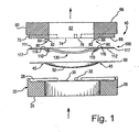
- Figure 1 is an exploded cross-sectional view of a bursting disc assembly,
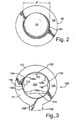
- Figure 2 is a top view of a rupture disc,
- Figure 3 is a top view of a support ring,
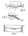
- Figure 4 is a cross-section view of the disc and support ring illustrating the transition diameter,
- Figure 5 is a enlarged view of the portion in circle A of Figure 4,
- Figure 6 is a top view of the lower holder,
- Figure 7 is a view of the upper holder viewed from below, and
- Figure 8 is a side view of the assembled device.
- For purposes of description herein the terms upper, lower, vertical and horizontal along with other directional references shall be relative to the invention as oriented in Figures 1 and 8, as illustrated in a pressure to non-pressure flow direction. It should also be understood that the various disclosed embodiments are merely exemplary and are utilized in a manner as would be readily understood by a person in the art.
- The assembly as generally indicated by
reference numeral 10, designates a rupture disc assembly including, in a pressure to non-pressure direction sequential relationship, a lower support holder orflange 20, arupture disc 50, asupport ring 100 and an upper support holder orflange 60. Theassembly 10 when in use is securely held in an assembled condition through any conventional means, such as through the use of bolts or other mounting arrangements. Thesupport ring 100 includes a projection ortongue member 121 formed in one side of thering 100, and acontinuous cutting surface 130 formed remaining non-projection sides of the ring (see Figure 3). - The
assembly 10 may be positioned within a safety release structure (not shown), such as a vent or pressure release valve assembly, and is normally adapted to prevent the flow of a liquid or a gas, in high and /or low pressures, through the assembly under a normal or predetermined burst pressure. Thedisc 50 is adapted to rupture or provide relief for excessive pressure when the predetermined maximum burst pressure of a bursting disc is exceeded. - When viewed from a pressure side to the non-pressure side of the
device 10, there is provided a lower support holder orflange 20, which is positioned adjacent the lower surface of a burstingdisc 50. The lower support holder orflange 20 may be constructed of any suitable material known in the art. The support holder orflange 20 in use is adapted to provide a secure seal against leakage between thedisc 50 and the portion of the pressure vessel into which theassembly 10 is placed. - As illustrated in Figure 6, the lower support holder or
flange 20 is of a generally circular or ring configuration, having a centralized aperture or bore 22, an innerperipheral wall 24 and an outercircumferential wall 26, a lower surface 25 (Fig. I) and an upper annular surface orinner seating surface 40 around thecentralized aperture 22 of theflange 20. In a preferred embodiment, theouter wall portion 26 of the lower holder orflange 20 extends above and around theannular surface 40, having a generally extending peripheralouter rim portion 28. Formed within thesurface 40, through any conventional means such as milling, die forming, tooling or the like, is a circumferential raised projection ormember 42, spaced inwardly of theouter rim wall 28. Raised member orprojection 42 is adapted to provide a protuberance against which disc 50 abuts. When theassembly 10 is in a fully assembled condition, the raised projection ormember 42 is adapted to securely retain thedisc 50 against thesupport ring 100 and thesupport holder 20. As theassembly 10 is assembled and secured through conventional means, the pressure between the flange portion of the disc and the raised projection ormember 42 allows for the flange portion to form or bend onto the projection thereby providing a seal and retaining thedisc 50 in place. - In a preferred embodiment, the
outer rim 28 is interrupted and provided with a gap portion orinterruption 30. Most preferably thegap portion 30 is provided or interrupted by asegment 32 of the outer rim or wall portion, wherein the segment or segments are adapted to match or fit with a corresponding or mating portion on a subsequent element of the assembly.
In a preferred embodiment, the raised projection ormember 32 is spaced midway between theouter rim 28 and theinner ring wall 24. - As illustrated in Figure 3, the
support ring 100 includes ahandle portion 120. Thesupport ring 100 is of a generally circular configuration, having anupper surface 111 and alower surface 112, the ring being adapted through dimension and position to fit snugly within theassembly 10 as shown in Figures 1 and 8. Thesupport ring 100 further includes acentral aperture 115, corresponding to that of the disc andflanges support ring 100 has an innerperipheral edge 116 and an outercircumferential edge 117 spaced apart by a generallyannular section 105. The innerperipheral edge 116 includes a projection, tongue orhinge member 121, a series ofdownward projections 110, and an opening pattern orcutting edge 130 extend either side of theprojections 110. The projection orhinge member 121 is formed at a predetermined point along the inner ring surface, the remaining portion providing the opening pattern orcutting edge 130. Thecutting edge 130 has a generally continuous configuration, which according to the present embodiment is of a generally clover leaf pattern. - As shown in Figure 1 , the
projections 110 and thecutting edge 130, andprojections 110 of thesupport ring 100, when viewed from a pressure side to a non-pressure side perspective, depend or otherwise extend downwardly below the horizontal axis of the supportingring 100. As shown in an assembled state, thecutting edge 130 and the hinge orprojection 121 depend into the concavity of adome portion 52 of thedisc 50, wherein the transition radius and diameter is substantially similar to that of the disc. The support ring innerperipheral edge 116, has atransition region 90 including a predetermined transition radius and transition diameter, discussed in detail below. - The opening pattern or cutting
edge 130 in the example shown in Figure 3, is of a generally clover leafconfiguration, extending continuously along the innerperipheral portion 116 of the supportingring 100. Most desirably, the cuttingmember 130 having a generally clover leaf configuration depends from the horizontal plane of thesupport ring 100 towards and within thedome portion 52 of thedisc 50. Thecutting edge 130 includes the tear initiation points 110, and arcuately curvedcontinuous cutting portions 134. Thecutting edge 130 has an angle generally being between 50 and 70 degrees, and most desirably about 60 degrees. The arcuately curved cuttingportions 134 includeinner arcs 134a which substantially coincide with abore 62 of anupper support holder 60. - The
configuration cutting edge 130 provides for a non-fragmenting burst pattern of the disc, although other suitable angles may be used. A method of forming this cutting pattern is described in further detail below. - As shown in Figure 3, the outer circumferential edge of the
support ring 100 includes thehandle projection 120. Formed within thehandle projection 120 through any conventional means is a slot oraperture 106, adapted to aid in the proper assembling of theassembly 10 by being able to precisely position thesupport ring 100 with respect to the lower holdingmember 20. - As illustrated in Figures 1 and 2, the
disc 50 is ofa conventional type commonly referred to as a reverse buckling disc, fabricated from a conventional metal material such as steel, steel alloy or other, and is adapted to tear upon reversing along thepredetermined cutting pattern 130 on thesupport ring 100 when a pressure load exceeds the predetermined pressure load of therupture disc 50. Therupture disc 50 includes the central portion ordome portion 52, and a flange orrim portion 54, and is adapted to be positioned with thedome 52 facing in a pressure flow direction between thesupport ring structure 100 and thelower flange 20.Disc 50, when in use and under excessive pressure, is adapted to reverse buckle towards thesupport ring 100 and theprojection member 120. Thedome portion 52 of thedisc 50 is cut or otherwise opened against the clover leafpattern cutting edge 130 immediately after which the burst or buckleddisc 50 is wrapped around thehinge projection 121. - The
disc 50 may be of any conventional type, such as a non-scored reverse bursting disc. When utilized in accordance with the present invention, no score lines are required as thesupport ring 100 as described in detail below includes a cutting formation which provides for the serration and non-fragmentation of thedisc 50. According to a preferred embodiment, when using a non-scored reverse buckling disc, the present invention is able to be utilized within both gaseous and liquid environments, and for both high and low burst pressures in both gaseous and liquid environments. - Most preferably, the
disc 50 includes a transition region 45 (Figure 2) having a predetermined transition radius and diameter, and the support ring includes atransition region 90 having a predetermined transition radius and diameter. The transition radius between thedome portion 52 of therupture disc 50 and theperipheral portion 54 is approximately identical in both therupture disc 50 and thesupport ring 100. Desirably, the diameter of the transition radius of thesupport ring 100 is approximately 0.010" to 0.020" smaller than the transition radius of thedisc 50. - As illustrated in Figures 4 and 5, the transition diameter and radius of the
support ring 100 and thedisc 50, as indicated above, are substantially similar, with the support ring being adapted through dimension and position to coincide with thedisc 50. Thetransition region 90 of thesupport ring 100, shown in Figures 4 and 5, has a generally predetermined diameter and radius corresponding to that ofdisc 50. These ratios of course will vary depending upon the size and diameter of the disc being used, as will be understood by one skilled in the art. - A second upper holder or
flange 60 is positioned abutting thesupport ring 100, as shown in Figures 1 and 7, on the non-pressure side of thedisc 50. The upper support holder orflange 60 is adapted to provide a secure seal against leakage between thenon-burst disc 50 and the non-pressure side of theassembly 10 when placed within a pressure vessel. Theupper support holder 60 is similar to that of the lower support holder orflange 20, wherein the upper or non-pressure side support holder orflange 60 has a generally cylindrical configuration including acentral aperture 62, having a defined bore dimension, acontinuous side wall 65 and upper andlower surfaces upper support holder 60 includes a corresponding ormating portion 70 having a circumferential or annular seat to that of the outer rim offlange 20. Alternatively, themating portion 70 of theupper support holder 60 is interrupted by spaced apartprojections Projections segment portions outer rim 28. The corresponding projections of theupper support holder 60 aid in the proper seating and assembly of thering assembly 10 by ensuring that the gap portions and projections are mated correctly in an abutting relationship. If the upper andlower support holders - Desirably, as shown in Figures 1 and 7, the
bore 62 of theupper support holder 60 is provided with dependingprojections 80 adapted to support thecutting edge 130. Dependingsupport 80 include correspondingsupport projections 82 adapted to aid in supporting the support ring cutting or tear initiation points 110. Dependingsupport 80 includes arcuatelycurved sections 84 adapted to reinforce or support arcuatelycurved members 134. The dependingsupport 80, aids in supporting thecutting edge 130 when the predetermined burst pressure of a reverse rupture disc has been exceeded and thedisc 50 reverses and is cut open on thetear initiating members 110 and thecutting edge 130. Typically, this pressure is substantial and the bursting of thedisc 50 is quite rapid and places pressure upon the supportring cutting edge 130. As such it is desirable to support the cutting pattern in such a way that substantially all of the cutting surfaces are supported against undesirable bending or twisting during the serration or cutting of thedisc 50. Most preferably theprojections 80 have the substantially similar transition radius and transition diameter to that of thesupport ring 100 andrupture disc 50. By having the innermost segments of the contoured configurations coincide with the defined bore of theupper support holder 60, the present invention enables abursting disc 50 to be applicable for both gas and liquid applications and for high and low pressure applications. - In use, the
assembly 10 is clamped in a pressure line (not shown). The lower support holder orflange 20 is placed toward the pressure flow, followed in an abutting and sealed sequential relationship, thereverse buckling disc 50, thesupport ring 100 and the upper support holder orflange 60, positioned such that any pressure must first contact thedisc 50. When pressure in the vessel is greater than the rupture pressure of therupture disc 50, the reverse disc pressure load is exceeded and upon rupture, the pressure is relieved through theassembly 10. - As the
rcvcrsc buckling disc 50 reverses upon itself, the dome or concaveconvex portion 52 of thedisc 50 is forced against thecutting edge pattern 130 of thesupport ring 100. Thecutting pattern 130 effectively cuts thedisc 50 along the continuous cutting edge such that the cutaway portion of the disc folds or hinges along theprojection member 121. - In a further alternative embodiment, the upper support holder or
flange 60 includes a dependingprojection 80, having a substantially similar configuration to that of the cutting pattern of thesupport ring 100. This dependingprojection 80 provides for additional support of thecutting edge 130 during the bursting of thedisc 50. - Desirably, a method for forming the
support ring 100 includes providing a blank for use as a support ring is manufactured through conventional means, ie pressing, cutting etc., resulting in a bulged out or domed shape configuration. Ideally, once formed, thedisc 50 includes theflange portion 54, and the concave/convex dome 52, and apredetermined transition region 45 having a transition radius and transition diameter β substantially equal to that of acorresponding support ring 100. As understood, the term transition radius used herein is used to describe the area between the flange portion of the disc and the dome portion of the disc having a predetermined radius and angle. The transition diameter is understood to describe the length of the area between the flange sides. - In a preferred embodiment, the transition diameter of the
transition region 90 of thesupport ring 100 has a predetermined length α (Figure 4), which is substantially similar to that of the of the transition diameter β (Figure 2) of thedisc 50. The substantially similar transition diameters (α and β) provide for a closer or more snug fit between thedisc 50 and thesupport ring 100 which allows for less movement of the disc upon burst and aids in the efficient cutting of thedisc 50 upon the tear initiation points or cuttingpoints 110 andarcuate cutting members 134. - A preferred method of forming the
cutting edge pattern 130 of thesupport ring 100 is utilizing a precision cutting means, such as a laser, to effectively cut or otherwise form the cloverleaf cutting pattern 130 in the pre-formed blank. This provides for a more precise cutting of the support ring surface, as the laser optimally cuts at a 90 degree angle to the ring surface. The laser provides (or forms) a cutting edge having a predetermined angle extending for at least a major portion of the pattern. As stated, thecutting edge 130 has a predetermined angle of between 50 and 70 degrees, and most preferably has a cutting angle of approximately 60 degrees. - Although embodiments of the invention have been described above, it is not limited thereto and it will be apparent to those skilled in the art that numerous modifications form part of the present invention insofar as they do not depart from the scope of the claimed invention.
Claims (5)
- A bursting disc assembly comprising a rupture disc assembly (10) which includes a reverse buckling rupture disc (50), a support ring (100) to support said reverse buckling rupture disc (50) and which is in contact therewith, and a support holder member or flange (60) for mounting said rupture disc assembly (10) with said rupture disc (50) being spaced from said support holder member or flange (60), characterized in the assembly further comprising:a support holder member or flange (60) having an upper and a lower surface (66, 68);a central aperture (62) in said support holder member or flange (60) defined by an inner peripheral wall (64) of the support holder member or flange (60); whereinone of said upper and lower surfaces (66, 68) includes a supporting projection (80) extending beyond one of said upper or lower surfaces (66, 68), said projection (80) bounding at least a portion of said aperture (62), said projection (80) configured to support an angled cutting portion (134) of the support ring (100) for seating on the said one of said upper and lower surfaces (66, 68) having said projection (80) with the angled cutting portion (134) of the support ring (100) extending away from the support holder member or flange (60).
- The bursting disc assembly of claim 1, wherein said support holder member or flange (60) has a plurality of spaced apart supporting projections (80), each adapted to provide individual support to an individual angled cutting portion (134) of the support ring (100) when said support ring (100) is seated on said support holder member or flange (60).
- The bursting disc assembly of claim 1, wherein the assembly comprises first (60) and second (20) holder members, whereby said first holder member is said support holder member or flange (60).
- The bursting disc assembly of claim 3, wherein each of said holder members (60, 20) further includes a cooperating mating portion (74, 76) to permit said first (60) and second (20) holders to releasably engage each other.
- The bursting disc assembly of claim 3 or 4, wherein the other of said holder members (20) has a recess adapted to receive said projection (80).
Applications Claiming Priority (3)
| Application Number | Priority Date | Filing Date | Title |
|---|---|---|---|
| US475182 | 1999-12-30 | ||
| US09/475,182 US6220269B1 (en) | 1999-12-30 | 1999-12-30 | Bursting disc assembly retaining ring with a clover leaf cutting pattern and projection |
| EP00986949A EP1242763B1 (en) | 1999-12-30 | 2000-12-28 | Bursting disc assembly |
Related Parent Applications (2)
| Application Number | Title | Priority Date | Filing Date |
|---|---|---|---|
| EP00986949.6 Division | 2000-12-28 | ||
| EP00986949A Division EP1242763B1 (en) | 1999-12-30 | 2000-12-28 | Bursting disc assembly |
Publications (3)
| Publication Number | Publication Date |
|---|---|
| EP1591703A2 EP1591703A2 (en) | 2005-11-02 |
| EP1591703A3 EP1591703A3 (en) | 2006-05-03 |
| EP1591703B1 true EP1591703B1 (en) | 2007-02-28 |
Family
ID=23886535
Family Applications (2)
| Application Number | Title | Priority Date | Filing Date |
|---|---|---|---|
| EP00986949A Expired - Lifetime EP1242763B1 (en) | 1999-12-30 | 2000-12-28 | Bursting disc assembly |
| EP05015717A Expired - Lifetime EP1591703B1 (en) | 1999-12-30 | 2000-12-28 | Bursting disc assembly |
Family Applications Before (1)
| Application Number | Title | Priority Date | Filing Date |
|---|---|---|---|
| EP00986949A Expired - Lifetime EP1242763B1 (en) | 1999-12-30 | 2000-12-28 | Bursting disc assembly |
Country Status (6)
| Country | Link |
|---|---|
| US (2) | US6220269B1 (en) |
| EP (2) | EP1242763B1 (en) |
| AU (1) | AU2337401A (en) |
| CA (1) | CA2329603A1 (en) |
| DE (2) | DE60027771T2 (en) |
| WO (1) | WO2001050050A1 (en) |
Families Citing this family (21)
| Publication number | Priority date | Publication date | Assignee | Title |
|---|---|---|---|---|
| US6006938A (en) * | 1997-09-18 | 1999-12-28 | Continental Disc Corporation | Enhanced reverse buckling rupture disc |
| US6220269B1 (en) * | 1999-12-30 | 2001-04-24 | Process Equipment Inc. | Bursting disc assembly retaining ring with a clover leaf cutting pattern and projection |
| CA2321939A1 (en) * | 2000-10-02 | 2002-04-02 | Process Equipment Inc. | Bursting disc assembly retaining ring with a clover leaf cutting pattern and projection |
| US7600527B2 (en) | 2005-04-01 | 2009-10-13 | Fike Corporation | Reverse acting rupture disc with laser-defined electropolished line of weakness and method of forming the line of weakness |
| US20080060702A1 (en) * | 2006-09-12 | 2008-03-13 | Scott Muddiman | Elliptical score pattern for reverse acting style rupture disc and assembly using the same |
| ES2622413T3 (en) * | 2007-06-18 | 2017-07-06 | Donadon Safety Discs And Devices S.R.L. | Method for producing safety / breakage discs that have a previously calculated break threshold |
| JP2013506802A (en) * | 2009-09-30 | 2013-02-28 | ビーエス アンド ビー セイフティー システムズ リミテッド | Rupture disc |
| US8714175B2 (en) * | 2010-02-24 | 2014-05-06 | Applied Separations, Inc. | Pressure relief system for pressure vessels |
| EP2565504A1 (en) | 2011-09-02 | 2013-03-06 | Aurotec GmbH | Connector of a transport pipeline |
| EP2565572A1 (en) | 2011-09-02 | 2013-03-06 | Aurotec GmbH | Heat exchange conduit system |
| WO2013038273A2 (en) * | 2011-09-16 | 2013-03-21 | Paul Goggin | Rupture disk and hinge |
| CN102606777A (en) * | 2012-03-26 | 2012-07-25 | 大连理工安全装备有限公司 | Composite type anti-arch slotted rupture disk |
| CN103545741B (en) * | 2012-07-16 | 2016-10-05 | 韩罗产业株式会社 | Rupture disk and gas insulated switchgear having the same |
| EP2743551A1 (en) | 2012-12-14 | 2014-06-18 | Aurotec GmbH | Blocking device with flushing |
| CN103291984A (en) * | 2013-05-16 | 2013-09-11 | 成都凯天电子股份有限公司 | Liquid-phase ultra-lower pressure totally-open fragment-free reverse-arch rupture disc device |
| US9289856B2 (en) | 2013-07-29 | 2016-03-22 | Fike Corporation | Creation of laser-defined structures on pressure relief devices via tiling method |
| JP2017071128A (en) * | 2015-10-07 | 2017-04-13 | 横浜ゴム株式会社 | Puncture repair liquid storage container |
| CN107477361B (en) * | 2016-11-23 | 2023-04-25 | 华东理工大学 | A combined bursting disc safety device for a high-pressure natural gas long pipe trailer and its application method |
| DE102021106903A1 (en) * | 2021-03-19 | 2022-09-22 | Konzelmann Gmbh | pressure equalization device |
| US12092232B2 (en) | 2021-04-26 | 2024-09-17 | Donaldson Company, Inc. | Polymeric rupture disk system |
| US12100855B2 (en) * | 2022-02-04 | 2024-09-24 | Mann+Hummel Gmbh | Hermetically closed battery degas venting unit for a battery enclosure/pack/housing |
Family Cites Families (26)
| Publication number | Priority date | Publication date | Assignee | Title |
|---|---|---|---|---|
| US3704801A (en) | 1970-11-04 | 1972-12-05 | Eugene V Stair | Falling tree controller and improved mower cutting device |
| US3704807A (en) | 1971-03-08 | 1972-12-05 | Ametek Inc | Safety relief device |
| US4046280A (en) | 1976-07-06 | 1977-09-06 | Continental Disc Corporation | Direct mounting reverse buckling disc |
| US4079854A (en) | 1976-08-09 | 1978-03-21 | Continental Disc Corporation | Rupture disc pressure relief device |
| US4211334A (en) * | 1977-09-12 | 1980-07-08 | B S & B Safety Systems, Inc. | Safety pressure relief apparatus |
| US4278181A (en) * | 1978-08-25 | 1981-07-14 | Bs & B Safety Systems, Inc. | Safety pressure relief device |
| US4301938A (en) * | 1978-08-25 | 1981-11-24 | Bs&B Safety Systems, Inc. | Safety pressure relief device |
| US4269214A (en) * | 1979-01-19 | 1981-05-26 | Bs & B Safety Systems, Inc. | Safety pressure relief device |
| US4236648A (en) | 1979-03-05 | 1980-12-02 | Black, Sivalls & Bryson | Safety pressure relief apparatus |
| US4342988A (en) | 1980-01-25 | 1982-08-03 | Continental Disc Corporation | Rupture disc alarm system |
| US4444214A (en) * | 1981-05-18 | 1984-04-24 | Continental Disc Corporation | Replaceable rupture disc cartridge arrangement |
| US4795051A (en) | 1982-05-24 | 1989-01-03 | Rs&B Safety Systems, Inc. | Rupturable fluid pressure relief apparatus and manufacturing method |
| US4682619A (en) * | 1983-07-05 | 1987-07-28 | Miner Clift | Reverse-buckling rupture disk |
| US4479587A (en) * | 1983-09-06 | 1984-10-30 | Bs&B Safety Systems, Inc. | Two-way rupturable pressure relief apparatus |
| IN160204B (en) | 1983-09-20 | 1987-06-27 | Continental Disc Corp | |
| US4669626A (en) | 1983-09-20 | 1987-06-02 | Continental Disc Corporation | Rupture disc with selectively positioned initial buckling |
| US4759460A (en) | 1983-09-20 | 1988-07-26 | Continental Disc Corporation | Rupture disc system |
| US4691729A (en) * | 1984-06-06 | 1987-09-08 | Clift Miner E | Reverse-buckling rupture disk with replaceable disk and blade |
| US4580691A (en) | 1985-01-11 | 1986-04-08 | Continental Disc Corporation | High flow pressure relief assembly |
| US5160070A (en) | 1988-08-11 | 1992-11-03 | Fike Corporation | Reverse bulged forward acting scored rupture disc bulkhead structure for multi-stage rocket motor |
| US5002088A (en) | 1989-08-30 | 1991-03-26 | Oseco Valve And Service Company, Inc. | Clean-in-place pressure and vacuum relief valve |
| US5082133A (en) * | 1991-08-01 | 1992-01-21 | Bs&B Safety Systems, Inc. | Low pressure rupture disk and assembly |
| US5365913A (en) | 1993-07-20 | 1994-11-22 | Walton Garry L | Rupture disc gas launcher |
| US5467886A (en) | 1994-11-14 | 1995-11-21 | Fike Corporation | Low burst pressure, multiple domed, scored rupture disc |
| GB9617679D0 (en) | 1996-08-23 | 1996-10-02 | Elfab Ltd | Pressure relief device |
| US6220269B1 (en) * | 1999-12-30 | 2001-04-24 | Process Equipment Inc. | Bursting disc assembly retaining ring with a clover leaf cutting pattern and projection |
-
1999
- 1999-12-30 US US09/475,182 patent/US6220269B1/en not_active Expired - Lifetime
-
2000
- 2000-12-27 CA CA002329603A patent/CA2329603A1/en not_active Abandoned
- 2000-12-28 DE DE60027771T patent/DE60027771T2/en not_active Expired - Fee Related
- 2000-12-28 DE DE60033706T patent/DE60033706T2/en not_active Expired - Fee Related
- 2000-12-28 WO PCT/CA2000/001576 patent/WO2001050050A1/en not_active Ceased
- 2000-12-28 EP EP00986949A patent/EP1242763B1/en not_active Expired - Lifetime
- 2000-12-28 EP EP05015717A patent/EP1591703B1/en not_active Expired - Lifetime
- 2000-12-28 AU AU23374/01A patent/AU2337401A/en not_active Abandoned
-
2001
- 2001-02-13 US US09/782,658 patent/US6349737B2/en not_active Expired - Fee Related
Also Published As
| Publication number | Publication date |
|---|---|
| AU2337401A (en) | 2001-07-16 |
| EP1242763A1 (en) | 2002-09-25 |
| EP1591703A2 (en) | 2005-11-02 |
| DE60027771T2 (en) | 2007-05-16 |
| DE60033706T2 (en) | 2008-04-17 |
| EP1242763B1 (en) | 2006-05-03 |
| US6220269B1 (en) | 2001-04-24 |
| WO2001050050A1 (en) | 2001-07-12 |
| US6349737B2 (en) | 2002-02-26 |
| DE60033706D1 (en) | 2007-04-12 |
| CA2329603A1 (en) | 2001-06-30 |
| EP1591703A3 (en) | 2006-05-03 |
| DE60027771D1 (en) | 2006-06-08 |
| US20010006075A1 (en) | 2001-07-05 |
Similar Documents
| Publication | Publication Date | Title |
|---|---|---|
| EP1242763B1 (en) | Bursting disc assembly | |
| JPH0639181Y2 (en) | Burst pressure relief device | |
| US6006938A (en) | Enhanced reverse buckling rupture disc | |
| JP3262927B2 (en) | Burst disc with multiple dome type and fold line | |
| US3722734A (en) | Safety relief device | |
| US5082133A (en) | Low pressure rupture disk and assembly | |
| US6178983B1 (en) | Rupture disk assembly | |
| US5022424A (en) | Tension loaded composite rupture disk | |
| CA2600952A1 (en) | Elliptical score pattern for reverse acting style rupture disc and assembly using the same | |
| US5558114A (en) | Eccentric scored rupture disk assembly | |
| US4436218A (en) | Reverse buckling bursting disc | |
| US6065485A (en) | Two-way pressure relief assembly and method | |
| US6298869B1 (en) | Reverse buckling, thermoformed, polymer rupture disk | |
| CA1286565C (en) | Safety pressure relief device and method for making the same | |
| EP0083473A1 (en) | Safety pressure relief device for pressure vessels | |
| US5720380A (en) | Reverse buckling disk with incorporated knife | |
| CA2321939A1 (en) | Bursting disc assembly retaining ring with a clover leaf cutting pattern and projection | |
| US4231484A (en) | Safety device for pressure vessels | |
| EP0395318A2 (en) | Safety pressure relief device for pressure vessels | |
| EP1078183B1 (en) | Enhanced reverse buckling rupture disc | |
| CA2560499C (en) | Enhanced reverse buckling rupture disc | |
| HK1035766B (en) | Enhanced reverse buckling rupture disc | |
| HK1006743B (en) | A multiple-dome, scored rupture disc |
Legal Events
| Date | Code | Title | Description |
|---|---|---|---|
| PUAI | Public reference made under article 153(3) epc to a published international application that has entered the european phase |
Free format text: ORIGINAL CODE: 0009012 |
|
| 17P | Request for examination filed |
Effective date: 20050722 |
|
| AC | Divisional application: reference to earlier application |
Ref document number: 1242763 Country of ref document: EP Kind code of ref document: P |
|
| AK | Designated contracting states |
Kind code of ref document: A2 Designated state(s): AT BE CH CY DE DK ES FI FR GB GR IE IT LI LU MC NL PT SE TR |
|
| AX | Request for extension of the european patent |
Extension state: AL LT LV MK RO SI |
|
| PUAL | Search report despatched |
Free format text: ORIGINAL CODE: 0009013 |
|
| AK | Designated contracting states |
Kind code of ref document: A3 Designated state(s): AT BE CH CY DE DK ES FI FR GB GR IE IT LI LU MC NL PT SE TR |
|
| AX | Request for extension of the european patent |
Extension state: AL LT LV MK RO SI |
|
| GRAP | Despatch of communication of intention to grant a patent |
Free format text: ORIGINAL CODE: EPIDOSNIGR1 |
|
| AKX | Designation fees paid |
Designated state(s): DE GB IE |
|
| GRAS | Grant fee paid |
Free format text: ORIGINAL CODE: EPIDOSNIGR3 |
|
| GRAA | (expected) grant |
Free format text: ORIGINAL CODE: 0009210 |
|
| AC | Divisional application: reference to earlier application |
Ref document number: 1242763 Country of ref document: EP Kind code of ref document: P |
|
| AK | Designated contracting states |
Kind code of ref document: B1 Designated state(s): DE GB IE |
|
| REG | Reference to a national code |
Ref country code: GB Ref legal event code: FG4D |
|
| REF | Corresponds to: |
Ref document number: 60033706 Country of ref document: DE Date of ref document: 20070412 Kind code of ref document: P |
|
| REG | Reference to a national code |
Ref country code: IE Ref legal event code: FG4D |
|
| PLBE | No opposition filed within time limit |
Free format text: ORIGINAL CODE: 0009261 |
|
| STAA | Information on the status of an ep patent application or granted ep patent |
Free format text: STATUS: NO OPPOSITION FILED WITHIN TIME LIMIT |
|
| 26N | No opposition filed |
Effective date: 20071129 |
|
| GBPC | Gb: european patent ceased through non-payment of renewal fee |
Effective date: 20071228 |
|
| PG25 | Lapsed in a contracting state [announced via postgrant information from national office to epo] |
Ref country code: IE Free format text: LAPSE BECAUSE OF NON-PAYMENT OF DUE FEES Effective date: 20071228 Ref country code: DE Free format text: LAPSE BECAUSE OF NON-PAYMENT OF DUE FEES Effective date: 20080701 |
|
| PG25 | Lapsed in a contracting state [announced via postgrant information from national office to epo] |
Ref country code: GB Free format text: LAPSE BECAUSE OF NON-PAYMENT OF DUE FEES Effective date: 20071228 |