EP1591658A2 - Engine starting system - Google Patents
Engine starting system Download PDFInfo
- Publication number
- EP1591658A2 EP1591658A2 EP05009350A EP05009350A EP1591658A2 EP 1591658 A2 EP1591658 A2 EP 1591658A2 EP 05009350 A EP05009350 A EP 05009350A EP 05009350 A EP05009350 A EP 05009350A EP 1591658 A2 EP1591658 A2 EP 1591658A2
- Authority
- EP
- European Patent Office
- Prior art keywords
- engine
- time
- cylinder
- speed
- stroke
- Prior art date
- Legal status (The legal status is an assumption and is not a legal conclusion. Google has not performed a legal analysis and makes no representation as to the accuracy of the status listed.)
- Withdrawn
Links
Images


Classifications
-
- F—MECHANICAL ENGINEERING; LIGHTING; HEATING; WEAPONS; BLASTING
- F02—COMBUSTION ENGINES; HOT-GAS OR COMBUSTION-PRODUCT ENGINE PLANTS
- F02N—STARTING OF COMBUSTION ENGINES; STARTING AIDS FOR SUCH ENGINES, NOT OTHERWISE PROVIDED FOR
- F02N99/00—Subject matter not provided for in other groups of this subclass
- F02N99/002—Starting combustion engines by ignition means
- F02N99/004—Generation of the ignition spark
-
- F—MECHANICAL ENGINEERING; LIGHTING; HEATING; WEAPONS; BLASTING
- F02—COMBUSTION ENGINES; HOT-GAS OR COMBUSTION-PRODUCT ENGINE PLANTS
- F02D—CONTROLLING COMBUSTION ENGINES
- F02D35/00—Controlling engines, dependent on conditions exterior or interior to engines, not otherwise provided for
- F02D35/02—Controlling engines, dependent on conditions exterior or interior to engines, not otherwise provided for on interior conditions
- F02D35/025—Controlling engines, dependent on conditions exterior or interior to engines, not otherwise provided for on interior conditions by determining temperatures inside the cylinder, e.g. combustion temperatures
- F02D35/026—Controlling engines, dependent on conditions exterior or interior to engines, not otherwise provided for on interior conditions by determining temperatures inside the cylinder, e.g. combustion temperatures using an estimation
-
- F—MECHANICAL ENGINEERING; LIGHTING; HEATING; WEAPONS; BLASTING
- F02—COMBUSTION ENGINES; HOT-GAS OR COMBUSTION-PRODUCT ENGINE PLANTS
- F02D—CONTROLLING COMBUSTION ENGINES
- F02D41/00—Electrical control of supply of combustible mixture or its constituents
- F02D41/02—Circuit arrangements for generating control signals
- F02D41/04—Introducing corrections for particular operating conditions
- F02D41/042—Introducing corrections for particular operating conditions for stopping the engine
-
- F—MECHANICAL ENGINEERING; LIGHTING; HEATING; WEAPONS; BLASTING
- F02—COMBUSTION ENGINES; HOT-GAS OR COMBUSTION-PRODUCT ENGINE PLANTS
- F02N—STARTING OF COMBUSTION ENGINES; STARTING AIDS FOR SUCH ENGINES, NOT OTHERWISE PROVIDED FOR
- F02N11/00—Starting of engines by means of electric motors
-
- F—MECHANICAL ENGINEERING; LIGHTING; HEATING; WEAPONS; BLASTING
- F02—COMBUSTION ENGINES; HOT-GAS OR COMBUSTION-PRODUCT ENGINE PLANTS
- F02N—STARTING OF COMBUSTION ENGINES; STARTING AIDS FOR SUCH ENGINES, NOT OTHERWISE PROVIDED FOR
- F02N11/00—Starting of engines by means of electric motors
- F02N11/08—Circuits or control means specially adapted for starting of engines
- F02N11/0851—Circuits or control means specially adapted for starting of engines characterised by means for controlling the engagement or disengagement between engine and starter, e.g. meshing of pinion and engine gear
-
- F—MECHANICAL ENGINEERING; LIGHTING; HEATING; WEAPONS; BLASTING
- F02—COMBUSTION ENGINES; HOT-GAS OR COMBUSTION-PRODUCT ENGINE PLANTS
- F02D—CONTROLLING COMBUSTION ENGINES
- F02D41/00—Electrical control of supply of combustible mixture or its constituents
- F02D41/02—Circuit arrangements for generating control signals
- F02D41/021—Introducing corrections for particular conditions exterior to the engine
- F02D41/0235—Introducing corrections for particular conditions exterior to the engine in relation with the state of the exhaust gas treating apparatus
- F02D41/0295—Control according to the amount of oxygen that is stored on the exhaust gas treating apparatus
-
- F—MECHANICAL ENGINEERING; LIGHTING; HEATING; WEAPONS; BLASTING
- F02—COMBUSTION ENGINES; HOT-GAS OR COMBUSTION-PRODUCT ENGINE PLANTS
- F02N—STARTING OF COMBUSTION ENGINES; STARTING AIDS FOR SUCH ENGINES, NOT OTHERWISE PROVIDED FOR
- F02N11/00—Starting of engines by means of electric motors
- F02N11/08—Circuits or control means specially adapted for starting of engines
- F02N11/0814—Circuits or control means specially adapted for starting of engines comprising means for controlling automatic idle-start-stop
- F02N11/0818—Conditions for starting or stopping the engine or for deactivating the idle-start-stop mode
-
- F—MECHANICAL ENGINEERING; LIGHTING; HEATING; WEAPONS; BLASTING
- F02—COMBUSTION ENGINES; HOT-GAS OR COMBUSTION-PRODUCT ENGINE PLANTS
- F02N—STARTING OF COMBUSTION ENGINES; STARTING AIDS FOR SUCH ENGINES, NOT OTHERWISE PROVIDED FOR
- F02N19/00—Starting aids for combustion engines, not otherwise provided for
- F02N19/005—Aiding engine start by starting from a predetermined position, e.g. pre-positioning or reverse rotation
- F02N2019/007—Aiding engine start by starting from a predetermined position, e.g. pre-positioning or reverse rotation using inertial reverse rotation
-
- F—MECHANICAL ENGINEERING; LIGHTING; HEATING; WEAPONS; BLASTING
- F02—COMBUSTION ENGINES; HOT-GAS OR COMBUSTION-PRODUCT ENGINE PLANTS
- F02N—STARTING OF COMBUSTION ENGINES; STARTING AIDS FOR SUCH ENGINES, NOT OTHERWISE PROVIDED FOR
- F02N2300/00—Control related aspects of engine starting
- F02N2300/20—Control related aspects of engine starting characterised by the control method
- F02N2300/2002—Control related aspects of engine starting characterised by the control method using different starting modes, methods, or actuators depending on circumstances, e.g. engine temperature or component wear
-
- F—MECHANICAL ENGINEERING; LIGHTING; HEATING; WEAPONS; BLASTING
- F02—COMBUSTION ENGINES; HOT-GAS OR COMBUSTION-PRODUCT ENGINE PLANTS
- F02N—STARTING OF COMBUSTION ENGINES; STARTING AIDS FOR SUCH ENGINES, NOT OTHERWISE PROVIDED FOR
- F02N2300/00—Control related aspects of engine starting
- F02N2300/20—Control related aspects of engine starting characterised by the control method
- F02N2300/2011—Control involving a delay; Control involving a waiting period before engine stop or engine start
Definitions
- the present invention relates to an engine starting system, and more particularly to an engine starting system for automatically stopping an engine in an operating state, such as idling state, when a given automatic stop condition is satisfied, and then restarting the engine when a given restart condition is satisfied.
- an operating state such as idling state
- Publication 1 JP 2002-4985 A1 [Hereinafter referred to as Publication 2] As measures for achieving a higher success rate in automatically restarting the automatically stopped engine, the Publication 1 further discloses a technique of controlling an exhaust valve closing timing after an ignition switch is turned off, so as to stop the engine at a given crank angle.
- a starter motor (motor for starting an engine) is additionally driven to provide enhanced reliability of engine starting, as disclosed, for example, In the Publication 2.
- the engine staring system as disclosed in the Publication 2 is designed to unexceptionally drive the starter motor when an engine start condition is satisfied In the state after an engine is completely stopped, as clearly described in the paragraph [0023] of the Publication 2. That is, even if a crankshaft is stopped at a position allowing for the so-called "direct start” (restart based on only combustion in a cylinder) by use of the control technique as disclosed in the Publication 1, the advantage of this control technique cannot be utilized. Thus, it can be hardly said that this system is adapted to sufficiently suppress electric power consumption.
- the system in the Publication 2 is designed such that a fuel is periodically injected into the cylinder in an expansion stroke, to maintain a given engine speed, during the period from the stop of the engine through until the engine start condition is satisfied. This control also leads to consumption of needless fuel.
- an object of the present invention to provide an engine starting system capable of automatically stopping an engine to improve fuel consumption, and quickly restarting the engine in a manner for minimizing the frequency in use of a starter motor and/or needless combustion to facilitate energy saving.
- the present invention provides an engine starting system for use in a vehicle equipped with a 4-stroke engine where one power cycle consisting of intake, compression, expansion and exhaust strokes is produced by two reciprocating motions of a piston.
- the engine includes: fuel supply means for supplying fuel into each of a plurality of cylinders; a plurality of spark plugs provided in the cylinders, respectively; rotational speed detection means for detecting an engine speed; and a start assist device adapted to drive a crankshaft of the engine using a motor.
- the engine starting system comprises: automatic stop control means operable, upon satisfaction of a predetermined automatic engine stop condition, to allow the supply of a fuel for maintaining an operating state of the engine to be interrupted so as to automatically stop the engine; start control means operable, upon satisfaction of a restart condition for restarting the automatically stopped engine, to allow the spark plug of at least the cylinder in the state after being stopped in an expansion stroke to ignite a fuel supplied into the cylinder and induce combustion in the cylinder, so as to automatically restart the engine: start-adequacy evaluation means for evaluating whether the engine start based on the start control means Is adequate; and assist drive control means operable, when the start-adequacy evaluation means determines that the engine start based on the start control means is inadequate, to drive the start assist device.
- the start-adequacy evaluation means Is operable to receive from said engine speed detection means an inspection engine speed defined by an engine speed detected at an inspection time which is set at a time when a given time lapses from initiation of the combustion In the cylinder in the state after being stopped In the compression stroke, and evaluate the adequacy of the engine start in accordance with the inspection engine speed; and the assist drive control means is operable, when the start-adequacy evaluation means determines that the inspection engine speed is less than a given engine speed required for adequately restarting the engine, to drive the start assist device around a zero-speed time when the crankshaft has a transition In rotation direction from a reverse direction occurring after an engine speed is lowered to zero, to a normal direction.
- an engine speed is detected at the inspection time.
- the so-called direct start fails, and then the start assist device is driven and associated with the engine having a relative low engine speed, to assist the restart of the engine.
- the start assets device includes a starter motor having a pinion gear engageable with a ring gear fixed to a flywheel of the engine.
- the starter motor to be used In the present invention is not limited to the type where a driving power is output from the pinion gear, but may be any other suitable type, such as a belt type.
- the assist drive control means is operable to drive the start assist device after the crankshaft has the transition in rotation direction from the reverse direction to the normal direction, and In a time range near to the second zero-speed time.
- the start assist device includes a pinion gear engageable with a ring gear provided in the engine, and the assist drive control means is operable to set around the zero-speed time an engagement time when the pinion gear is brought into' engagement with the ring gear, and drive the start assist device after completion of the engagement between the pinion gear and the ring gear.
- the pinion gear of the start assist device is brought into engagement with the ring gear after the crankshaft has the transition in rotation direction from the reverse direction to the normal direction and in a time range near to the second zero-speed time.
- the engine speed detection means is operable to send to the assist drive control means an assist-control reference time defined by a time when an engine speed is lowered from the inspection engine speed to zero, and the assist drive control means is operable to calculate the zero-speed time in accordance with the assist-control reference time and determine a time range of the engagement between the pinion gear and the ring gear in accordance with the calculated zero-speed time.
- the calculations for the engagement time can be initiated in the stage where the start-adequacy evaluation means determines evaluates the necessity of the start assist device, and quickly determine the engagement time between the pinion gear and the ring gear.
- the assist drive control means is operable to calculate a driving delay time-period in the start assist device, and determine an output time of a drive signal In accordance with the calculated driving delay time-period in such a manner as to allow the drive signal to be output to the start assist device at a time earlier than the zero-speed time.
- the driving delay time-period in the start assist device is included in one of control parameters.
- the start assist device has a time lag between the receiving of the drive signal and the driving of the engine, an intended assist initiation time can be reliably set.
- the start-adequacy evaluation means is operable, when the restart of the engine is successfully initiated, to estimate a time when the cylinder in the state after being stopped in an expansion stroke firstly reaches a top dead center In an exhaust stroke, so as to define the estimated time as the inspection time, and evaluate the adequacy of the engine restart in accordance with the inspection engine speed defined by an engine speed detected at the defined inspection time and received from the rotational speed detection means.
- the inspection time corresponding to the evaluation time for the start-adequacy evaluation means is set at the time when the cylinder in the state after being stopped in an expansion stroke firstly reaches a top dead center in an exhaust stroke, This makes it possible to determine the inspection time in accordance with a phase of the crankshaft corresponding to the inspection time.
- the success/fallure or adequacy of the so-called direct start is determined based on the engine speed at the inspection time.
- the start assist device will not be always driven. This can contributes to energy saving as compared the conventional technique disclosed in the aforementioned Publication 2.
- the start assist device can assist the engine start in the stage where a load to be imposed on the start assist device is minimum.
- the start assist device can have reduced load and enhanced reliability.
- this can contribute to enhancement In durability of the start assist device itself.
- the start assist device includes the pinion gear engageable with the ring gear associated with the engine
- the assist drive control means is operable, after the engine crankshaft has the transition in rotation direction from the reverse direction to the normal direction, to determine the timing of engagement with the pinion gear 36a in the time range near to the zero-speed time, and to allow the assist operation based on the start assist device to be initiated after the engagement between the pinion gear and the ring gear
- the engagement can be achieved without load onto the start assist device even in the type where the pinion gear is brought into engagement with the ring gear, in the state when it is rotated by driving motor In a direction opposite to that in which the ring gear is to be rotated,. This can contribute to enhancement in reliability and durability of the start assist device.
- the rotational speed detection means are operable to send to the assist drive control means an assist-control reference time defined by a time when an engine speed is lowered from the inspection engine speed to zero
- the assist drive control means is operable to calculate the zero-speed time in accordance with the received assist-control reference time and determine the time range of the engagement between the pinion gear and the ring gear in accordance with the calculated zero-speed time
- the assist drive control means is operable to calculate the driving delay time-period in the start assist device, and determine the an output time of the drive signal in accordance with the calculated driving delay time-period
- the driving delay time-period in the start assist device is included in one of control parameters.
- the start-adequacy evaluation means is operable to estimate a time when the cylinder in the state after stopped in an expansion-stroke cylinder first reaches a top dead center in an exhaust stroke, so as to defined the estimated time as the inspection time, and evaluate the adequacy of the engine restart in accordance with an inspection engine speed defined by the engine speed detected at the inspection time and received from the rotational speed detection means, the inspection time can be estimate relatively accurately. This has an advantage of being able to accurately evaluate the adequacy of the inspection engine speed and detect the inspection engine speed readily and accurately so as to achieve enhanced control accuracy.
- FIGS. 1 and 2 schematically show the structure of a four-stroke spark-ignition internal combustion engine having an engine starting system according to one embodiment of the present invention.
- This engine comprises an engine body 1 including a cylinder head 10 and a cylinder block 11, and an engine control ECU (electronic control unit) 2.
- the engine body 1 has four cylinders (a cylinder #1 or 12A, a cylinder #2 or 12B, a cylinder #3 or 12C and a cylinder #4 or 12D), and a piston 13 connected to a crankshaft 3 is slidably fitted In each of the cylinders 12A to 12D to define a combustion chamber 14 thereabove.
- a cylinder which is or was in a compression stroke during an after-mentioned automatic engine stop control, and a cylinder which is or was in an expansion stroke during the automatic engine stop control are referred to, respectively, as “compression-stroke cylinder” and “expansion-stroke cylinder” (in the same way, a cylinder which is or was in an intake position during the automatic engine stop control, and a cylinder which is or was in an exhaust stroke during the automatic engine stop control, are referred to, respectively, as “intake-stroke cylinder” and “exhaust-stroke cylinder”).
- each of these terms does not fixedly mean a specific cylinder, but expediently expresses each cylinder in accordance with the stroke of the cylinder during, or just before the completion of, the automatic engine stop control.
- the combustion chamber 14 in each of the cylinders 12A to 12D has a top wall portion provided with a spark plug 15 whose tip is exposed to the combustion chamber 14.
- Each of the spark plugs 15 is electrically connected to an ignition device 27 for activating the corresponding spark plug 15 to generate an electric spark therein.
- a fuel injection valve 16 is attached to a side wall portion of the combustion chamber 14 in each of the cylinders 12A to 12D to inject fuel directly into the combustion chamber 14,
- This fuel injection valve 16 internally having a needle valve (not shown) and a solenoid (not shown) is designed such that the solenoid is driven for a period of time corresponding to a pulse width of a pulse signal entered therein from a fuel injection control section 41 of the ECU 2, to open the needle valve so as to inject fuel in an amount proportional to the valve open period, toward and around electrodes of the spark plug 15.
- the combustion chamber 14 in each of the cylinders 12A to 12D also has an upper wall portion formed with an intake port 17 and an exhaust ports 18 each extending to open into the combustion chambers 14.
- the Intake port 17 is equipped with an intake valve 19, and each of the exhaust ports 18 is equipped with an exhaust valve 20.
- the intake valve 19 and the exhaust valve 20 are designed to be driven by a valve operating mechanism including a camshaft (not shown), so that respective opening/closing timings of the intake and exhaust valves 19, 20 in the cylinders 12A to 12D are set to allow a four-stroke combustion or power cycle to be performed in the cylinders 12A to 12D with a given phase differences therebetween.
- the intake port 17 and the exhaust port 18 are in fluid communication with an intake passage 21 and an exhaust passage 22, respectively.
- a downstream portion of the intake passage 21 on the side closer to the intake port 17 is formed as an intake manifold with four independent passages 21 a corresponding to the cylinders 12A to 12D, and respective upstream ends of the intake manifold passages 21 a are in fluid communication with a surge tank 21 b.
- An upstream portion of the intake passage 21 relative to the surge tank 21 b is formed as a common intake passage 21 c which is provided with a throttle valve 23 designed to be driven by an actuator 24.
- an air-flow sensor 25 for detecting an intake-air flow rate and an intake-air temperature sensor 29 for detecting an intake-air temperature are disposed on the upstream side of the throttle valve 23, and an intake pressure sensor 26 for detecting an intake pressure (negative pressure) is disposed on the downstream side of the throttle valve 23.
- a portion of the exhaust passage 22 on the downstream side of an exhaust manifold for collectively receiving exhaust gas from the cylinders 12A to 12D is provided with a catalytic converter 37 for purifying the exhaust gas.
- the catalytic converter 37 contains a three-way catalyst which exhibits a significantly high conversion rate of HC, CO and NOx when an air-fuel ratio of exhaust gas is close to a theoretical value. More specifically, the three-way catalyst has an ability of absorbing and storing oxygen therein in an oxygen-rich atmosphere or when exhaust gas has a relatively high oxygen concentration, and releasing the stored oxygen to induce a reaction with HC, CO, etc. when exhaust gas has a relatively low oxygen concentration.
- the catalyst to be used for the catalytic converter 37 is not limited to the three-way catalyst, but may be any other suitable catalyst having the aforementioned oxygen absorbing/storing ability, for example, the so-called lean NOx catalyst capable of purifying NOx in an oxygen-rich atmosphere.
- An alternator 28 is attached to the engine body 1 and connected to the crankshaft 3 through a timing belt or the like.
- This alternator 28 is internally provided with a regulator circuit 28a for controlling a current to be applied to a field coil (not shown) thereof to regulate an output voltage so as to adjust an output, and designed to be controlled according to a control signal sent from the ECU 2 to the regulator circuit 28a so as to generate an output in proportion, for example, to an electric load of a vehicle and a voltage of a battery mounted on the vehicle.
- the engine is provided with a pair of first and second crank angle sensors 30, 31 for detecting a rotational angle of the crankshaft 3.
- the first crank angle sensor 30 is operable to generate a detection signal for use in detecting an engine speed.
- the first and second crank angle sensors 30, 31 are arranged to generate detection signals having a phase lag, and these detection signals are used to detect a rotation direction and a rotational angle of the crankshaft 3, as described later in more detail.
- the engine body 1 is also provided with a cam angle sensor 32 for detecting a specific rotational position of the camshaft to discriminate the cylinders from each other, and a coolant temperature sensor 33 for detecting an engine coolant temperature.
- a cam angle sensor 32 for detecting a specific rotational position of the camshaft to discriminate the cylinders from each other
- a coolant temperature sensor 33 for detecting an engine coolant temperature.
- an accelerator-pedal angle sensor 34 is associated with an accelerator pedal mounted on the vehicle body to detect an accelerator-pedal angle corresponding to a displacement of the accelerator pedal caused by a driver's operation.
- a flywheel (not shown) and a ring gear 35 fixed to the flywheel are fixedly attached to the crankshaft 3 concentrically with respect to the rotational axis of the crankshaft 3.
- the ring gear 35 is an input member for a starter motor 36 serving as a start assist device, and designed to be engageable with an after-mentioned pinion gear 36d of the starter motor 36.
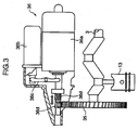
- the starter motor 36 includes a driving motor 36a, an electromagnetically- driven plunger 36b disposed parallel to the driving motor 36a, and a pinion gear 36d which is slidably fitted on an output shaft of the driving motor 36a in a non-rotatable manner relative to the output shaft, and adapted to be reciprocatingly moved along the output shaft by the plunger 36b through a shifting lever 36c.
- the plunger 36b is operable to move the pinion gear 36d from a standby position indicated by the solid lines in FIG. 3 to an engagement position indicated by the two-dot chain lines in FIG. 3 and bring the pinion gear 36d Into engagement with the ring gear 35 so as to rotatively drive the crankshaft 3 to restart the engine.
- the pinion gear 36d of the starter motor 36 employed in this embodiment has helically twisted teeth. Further, in order to facilitate the engagement with the ring gear 35, the starter motor 36 is designed such that, when the ring gear 35 stops, the pinion gear 36d is rotated at a speed of about 60 rpm in a direction opposite to a direction in which the ring gear 35 is to be rotated, and brought into engagement with the ring gear 35.
- the ECU 2 is a control unit for generally controlling operations of the engine.
- the engine starting system is designed to perform a control mode (idling stop mode) for interrupting (cutting) fuel to be injected to the cylinders 12A to 12D upon satisfaction of a predetermined automatic engine stop condition to automatically stop the engine, and then automatically restarting the engine upon satisfaction of a predetermined restart condition, e.g. for example, a driver's operation of the accelerator pedal.
- a control mode for interrupting (cutting) fuel to be injected to the cylinders 12A to 12D upon satisfaction of a predetermined automatic engine stop condition to automatically stop the engine, and then automatically restarting the engine upon satisfaction of a predetermined restart condition, e.g. for example, a driver's operation of the accelerator pedal.
- the ECU 2 In response to receiving respective detection signals from the air-flow sensor 25, the intake pressure sensor 26, the intake-air temperature sensor 29, the crank angle sensors 30, 31, the cam angle sensor 32, the coolant temperature sensor 33 and the accelerator-pedal angle sensor 34, the ECU 2 is operable to generate and send drive signals, respectively, to the fuel injection valves 16, the actuator 24 of the throttle valve 23, the ignition device 27, the regulator circuit 28a of the alternator 28, and the starter motor 36.
- the ECU 2 functionally includes a fuel injection control section 41, an ignition control section 42, an intake-air flow-rate control section 43, an alternator output control section 44, a piston position detection section 45, an in-cylinder temperature estimation section 46, an automatic stop control section 47, a start control section 48, a start-adequacy evaluation section 49, an air-fuel ratio control section 50 and a catalyst temperature estimation section 52.
- the fuel injection control section 41 serves as fuel injection control means for setting a fuel injection timing and a fuel injection amount in each fuel injection timing, and sending a control signal representing them to the fuel injection valves 16. Particularly in this embodiment, a split injection technique is used to supply a fuel for inducing a first combustion in an expansion-stroke cylinder during the engine restart control, as described later in more detail.
- the fuel injection control section 41 is also operable to set split injection timings and a fuel split ratio.
- the ignition control section 42 is operable to set a suitable ignition timing for each of the cylinders 12A to 12D, and send an ignition signal to each of the ignition devices 27.
- the intake-air flow-rate control section 43 is operable to set a suitable intake-air flow rate for each of the cylinders 12A to 12d, and send a throttle opening signal corresponding to the intake-air flow rate to the actuator 24 of the throttle valve 23.
- the opening of the throttle valve 23 is controllably adjusted to allow the piston 13 to be stopped at a position falling within an adequate range for restart of the engine, as described later in more detail.
- the intake-air flow-rate control section 43 is also operable to adjust the opening of the throttle valve 23 for this purpose,.
- the alternator output control section 44 is operable to set a desired target output of the alternator 28, and send a drive signal corresponding to the target output to the regulator circuit 28a. Particularly in this embodiment, during the automatic engine stop control, the output of the alternator 28 is controllably adjusted to change a load onto the crankshaft 3, so as to allow the piston 13 to be stopped at a position falling within an adequate range for restart of the engine, as described later in more detail. Thus, the alternator output control section 44 is also operable to adjust the output of the alternator 28 for this purpose.
- the alternator output control section 44 is operable to allow the alternator 28 to generate a slightly larger output than that in a normal operation so as to increase an engine load to prevent the occurrence of surging (excessively rapid increase in engine speed).
- the piston position detection section 45 is operable to detect a piston position in accordance with respective detection signals of the crank angle sensors 30, 31.
- a crank position and a crank angle (°CA) correspond one-to-one with one another.
- a piston position is indicated by a crank angle as in a common practice.
- an air quantity in each of the expansion-stroke and compression-stroke cylinders is calculated based on each piston position of the cylinders during the automatic engine stop control to control combustion in each cylinder in accordance with the calculated air quantity, as described later In more detail.
- the in-cylinder temperature estimation section 46 serves as in-cylinder temperature estimation means for estimating an in-cylinder air temperature in each of the cylinders 12A to 12D in accordance with an engine-coolant temperature detected by the coolant temperature sensor 33, an intake-air temperature detected by the intake-air temperature sensor 29 or the like and by use of a map experimentally prepared in advance or the like. Particularly In this embodiment, during the engine restart control, an in-cylinder temperature is estimated in consideration of an engine stop time, or a lapsed time after stop of the engine, to perform the combustion control in accordance with the estimated value, as described later in more detail.
- the automatic stop control section 47 serves as automatic stop control means for allowing the fuel injection to be interrupted upon satisfaction of a given engine stop condition during idling, so as to automatically stop the engine, as described later in more detail.
- the start control section 48 serves as start control means for allowing the automatically stopped engine to be automatically restarted upon satisfaction of an engine restart condition.
- the engine restart control if the stop position of each piston 13 falls within an after-mentioned specific range (adequate range), a certain amount of fuel is injected to at least an expansion-stroke cylinder In the state after stop of the engine, and ignited to induce combustion therein.
- an initial combustion is induced in a compression-stroke cylinder in the state after stop of the engine to move the piston 13 of the compression-stroke cylinder downward, whereby the piston of an expansion-stroke cylinder is moved upward to provide an increased in-cylinder pressure therein.
- the start control section 48 also serves as assist drive control means.
- the start-adequacy evaluation section 49 serves as start-adequacy evaluation means for evaluating the adequacy of engine restart by receiving Inputs from the piston position detection section 45 and the sensors 30, 31 serving as an engine speed detection section, and using an inspection engine speed defined by an engine speed detected at Inspection Time t12 (see FIG. 11) set after the lapse of a given time from initiation of the combustion in the expansion-stroke cylinder.
- the air-fuel ratio control section 50 serves as air-fuel ratio control means for calculating an air-fuel ratio, and determine a fuel amount to be distributed by the fuel injection control section 41 and an intake-air flow-rate to be controlled by the intake-air flow-rate control section 43.
- the catalyst temperature estimation section 52 serves as catalyst temperature estimation means for estimating a temperature of the catalytic converter 37 in accordance with an intake-air temperature detected by the intake-air temperature sensor 29 or the like and by use of a map experimentally prepared in advance or the like. Particularly in this embodiment, during the engine restart control, the catalyst temperature estimation section 52 is operable to estimate a temperature of the catalytic converter 37 so as to allow the fuel injection and the combustion control to be performed in accordance with the estimated value, as described later In more detail.
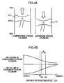
- the engine restart control is performed as follows. Initially, combustion is induced in the compression-stroke cylinder to move the piston 13 of the compression-stroke cylinder downward so as to reversely rotate the crankshaft 3. Thus, the piston 13 of the expansion-stroke cylinder is moved upward (closer to a top dead center (TDC)) to compress air (air-fuel mixture after the fuel injection) in the expansion-stroke cylinder. In this state, the air-fuel mixture is ignited and burnt to give a driving torque in a normal rotation direction to the crankshaft 3 so as to restart the engine.
- TDC top dead center
- the expansion-stroke cylinder can have an increased air quantity to obtain sufficient combustion energy, as shown in FIG. 4(b).
- BDC bottom dead center
- the ECU 2 (automatic stop control section 47) performs the following control to allow the piston 13 to be stopped at a position falling within the adequate stop range R.
- FIG. 5 is a time chart showing an engine speed Ne, a boost pressure Bt (intake pressure) and an opening K of the throttle valve 23, during an automatic stop control based on the automatic stop control section 47.
- FIG. 6 is an enlarged diagram of a portion of FIG. 5 just before and after Time t1, wherein changes in crank angle CA and transitions of the strokes in each of the cylinders are additionally illustrated.
- the following description will be made on the assumption that the cylinders #1 or 12A, #2 or 128, #3 or 12C, #4 or 12D are expansion-stroke, exhaust-stroke, compression-stroke and intake stroke cylinders, respectively.
- a target engine speed (idling engine speed when the automatic stop condition is satisfied) is stabilized at a value slightly greater than a normal idling engine speed in engine operations without the automatic engine stop control (hereinafter referred to as "normal idling engine speed). For example, if the engine has the normal idling engine speed set at 650 rpm (when an automatic transmission is operated in a drive (D) state), the target engine speed will be set at about 850 rpm (when the automatic transmission is operated in a neutral (N) range). Further, the opening K of the throttle valve 23 is adjusted to allow the boost pressure Bt to be stabilized at a relatively high given value (about - 400 mmHg).
- the fuel injection is interrupted to lower the engine speed Ne. Further, at Time t1 when the fuel injection is interrupted or in the initial stage of the automatic engine stop control, the opening K of the throttle valve 23 is increased to allow the intake-air quantity to be greater than that in an idling operation under the condition that an in-cylinder air-fuel ratio is set to have an excess air ratio ⁇ of 1 (a minimum intake-air quantity required for maintaining an engine operation).
- the opening K of the throttle valve 23 will be increased (for example, up to about 30 %). If the engine is operated in stratified combustion just before Time t1 by use of an air-fuel mixture set to have a lean in-cylinder air-fuel ratio, the opening K of the throttle valve 23 will be maintained as is (at a relatively large opening in the stratified combustion).
- FIGS. 5 and 6 show the former case.
- the boost pressure Bt starts increasing slightly after Time t1 (if the engine is operated in homogeneous combustion just before Time t1), or keeps at a relatively high value (if the engine is operated in stratified combustion just before Time t1), to facilitate scavenging in the combustion chamber.
- the air is introduced Into the cylinder #4 or 12D, the cylinder #2 or 12B, the cylinder #1 or 12A and the cylinder #1 or 12C in this order, as seen in FIG. 6.
- the cylinder #1 or 12A expansion-stroke cylinder
- the cylinder #1 or 12A compression-stroke cylinder
- the solid line indicates a crank angle under the condition that TDCs of the first and third cylinders 12A, 12C are set at 0 (zero)°CA
- the one-dot chain line indicates a crank angle under the condition that TDCs of the second and fourth cylinders 12B, 12D are set at 0 (zero)°CA.
- the solid line and the one-dot chain line become opposite in phase on the basis of 90°CA.
- a time when each piston of the cylinders reaches a compression TDC corresponds to a time when each of the rise-fall waves of the engine speed Ne has a bottom. This means that the engine speed Ne is gradually lowered in such manner as to it temporarily falls off every time each piston of the cylinders reaches a compression TDC and then rises at the time when the piston passes through the compression TDC to form the jiggly rise-fall waves.
- each stop position of the pistons 13 is almost determined by the balance between the respective compressive reaction forces in the compression-stroke cylinder 12C and the expansion-stroke cylinder 12A. Further, the piston stop positions are affected by an air-intake resistance in the suction-stroke cylinder 12D and a frictional resistance of the engine, and varied depending on a rotational inertia force of the engine or the level of the engine speed Ne at Time t4 when the piston of the cylinder 12A passes through the last compression TDC.
- the ECU 2 in this embodiment performs a control for allowing a given TDC engine speed Ne (particularly, the 2nd TDC (Time t3) to the last compression TDC just before stop of the engine is important) during the process of lowering in the engine speed Ne, to fall within a given speed range so as to more reliably stop the piston 13 of the expansion-stroke cylinder 12A at a position falling within the adequate stop range R.
- the output of the alternator 28 is increased or reduced to adjust the load of the crank shaft 3 (engine load) so as to allow the 2nd TDC engine speed Ne (Time t3) to the last TDC engine speed Ne just before stop of the engine to be set in the range of 350 ⁇ 50 rpm.
- the air-intake resistance acting on the piston 13 of the intake-stroke cylinder 12D is increased when the piston 13 of the intake-stroke cylinder 12D is moved toward the BDC, so that the piston 13 of the intake-stroke cylinder 12D is apt to be stopped on the side of the TDC relative to a target position.
- the respective pistons 13 of the intake-stroke and expansion-stroke cylinders 12D, 12A are moved in the same phase.
- the piston 13 of the expansion-stroke cylinder 12A is liable to be stopped at an undesirable position on the side of the TDC relative to the target position.
- K1 about 40 %
- the ECU 2 is operable to determine a time of the passing of the last compression TDC. Specifically, ECU 2 compares the engine speed detected at a time of the passing of each TDC with a given engine speed (e.g.
- the balance of respective intake-air flow rates of the expansion-stroke and compression-stroke cylinders 12A, 12C just before stop of the engine is also affected by the boost pressure Bt.
- the time (Time t3 in FIG. 6) of the passing of the 2nd compression TDC to the last compression TDC just before stop of the engine corresponds to the initial point of the last intake stroke in the compression-stroke cylinder 12C, and thereby a value of the boost pressure Bt at Time t3 has a great impact.
- the conditions allowing the piston 13 of the expansion-stroke cylinder 12A to be stopped at a position on the side of the last phase of the stroke are overlapped to provide higher possibility of being stopped at the target position (100 to 120°CA after the TDC).
- the control for increasing the opening of the throttle valve 23 up to K1 at Time t3 the piston stop position will be located closer to the last phase of the stroke to cause the risk of deviating from the target stop position.
- the opening of the throttle valve 23 at Time t3 is set at the opening K2 (see FIG. 6) less than K1 (or zero opening) to suppress increase in intake-air flow rate so as to prevent the piston stop position of the expansion-stroke position from being excessively moved toward the BDC.
- FIG. 7 is a flowchart showing the process of detecting the piston stop position.
- a first crank angle signal CA1 from the crank angle sensor 30
- a second crank angle signal CA2 from the crank angle sensor 31
- it is determined whether the second crank angle signal CA2 is "High" at the up edge of the first crank angle signal CA1 (Step S41). According to this determination, it is determined which of relationships illustrated in FIG. 8(a) and 8(b) each of the phases of the signals CA1, CA2 has. Then, based on this determination, it is determined whether the engine crankshaft is rotated in the normal direction.
- the second crank angle signal CA2 when the engine crankshaft is rotated in the normal direction, the second crank angle signal CA2 is generated with a phase delay of about half pulse width relative to the first crank angle signal CA1, as shown in FIG. 8(a). Thus, the second crank angle signal CA2 becomes “Low” at the up edge of the first crank angle signal CA1, and becomes “High” at the down edge of the first crank angle signal CA1.
- the second crank angle signal CA2 when the engine crankshaft is rotated in the reverse direction, the second crank angle signal CA2 is generated with a phase advance of about half pulse width relative to the first crank angle signal CA1, as shown in FIG. 8(b).
- the second crank angle signal CA2 in contradiction to the case where the engine crankshaft is rotated in the normal direction, the second crank angle signal CA2 becomes “High” at the up edge of the first crank angle signal CA1, and becomes “Low” at the down edge of the first crank angle signal CA1.
- Step S41 a CA counter for measuring changes in crank angle in a direction corresponding to the normal rotation direction of the engine crankshaft will be incremented (Step S42). If the determination at Step S41 is made as NO, the CA counter will be decremented (Step S43). Then, after stop of the engine, the measured value is checked to determine the piston stop positions (Step S44).
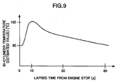
- FIG. 9 is a graph showing the relationship between a lapsed time from the stop of the engine and the in-cylinder temperature, specifically, estimated values of in-cylinder temperature change wherein the in-cylinder temperature at the time when the engine is stopped (Time 5) is 80°C.
- the in-cylinder temperature estimation section 46 stores data of these characteristics in the form of a map.
- the opening K of the throttle valve 23 may be increased to provide enhanced scavenging so as to allow a sufficient amount of flesh air to be supplied to the catalytic converter 37.
- the catalyst in the catalytic converter 37 has a sufficient amount of absorbed oxygen during the engine stop.
- TDC compression top dead center in each of the cylinders 12A to 12d
- B the periods before and after the piston is moved beyond are indicated by "B” and "A”, respectively.
- combustion is initially induced In the compression-stroke cylinder 12C to reversely rotate the engine crankshaft (reverse rotation operation), and then the combustion is induced in the expansion-stroke cylinder 12A to rotate the engine crankshaft in the normal direction again (normal rotation operation), as mentioned above. That is, the piston 13 of the expansion-stroke cylinder 12A is firstly moved upward to increase the compression pressure therein by reversely rotating the engine crankshaft, and then combustion is induced in the expansion-stroke cylinder 12A.
- the piston stop position in the expansion-stroke cylinder 12A stopped at a position falling within the adequate range with a sufficient air quantity therein, and the air compressed by the reverse rotation, can provide large combustion energy. This makes it possible to reliably rotate the engine crankshaft in the normal direction and assure a smooth transition to a subsequent continuous engine operation.
- the presence of the sufficient air in the expansion-stroke cylinder 12A hinders the air from strongly compressed. This is caused by the compressive reaction force from the compressed air which acts as a force pushing back the piston 13 of the expansion-stroke cylinder 12A.
- the ECU 2 performs a control for delaying the timing of fuel injection for the expansion-stroke cylinder 12A to allow the compression rate (density) of air in the expansion-stroke cylinder 12A to be increased.
- the fuel injection timing is delayed, the fuel is injected into the cylinder having the in-cylinder air compressed to some extent, and the compression pressure is reduced by the latent heat of vaporization of the injected fuel.
- the piston 13 can be moved to a position closer to the TDC (increase in piston stroke or moving distance) to provide further increased density of compressed air.
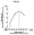
- FIG. 10 is a graph showing the relationship between a fuel injection timing for the expansion-stroke cylinder 12A and a reachable piston position (piston position closest to the TDC without ignition) based on the fuel injection timing, or showing an effect of fuel injection delay.
- the horizontal axis represents a crank angle (after top dead center: ATDC) corresponding to a fuel injection timing for the Initial combustion in the expansion-stroke cylinder 12A
- the vertical axis represent a crank angle (after top dead center: ATDC) corresponding to a reachable piston position in the expansion-stroke cylinder 12A based on the fuel injection timing.
- the in-cylinder volume at a maximum compression becomes smaller (higher air density) to provide larger combustion energy.
- the characteristic in FIG. 10 is obtained when the piston stop position of the expansion-stroke cylinder 12A is 110°C (ATDC).
- the reachable piston position is about 36.5°CA (ATDC).
- the reachable piston position can be changed to 33.5°CA (ATDC) to obtain an increased density of compressed air coresponding to about 3°CA.
- the fuel injection timing is preferably set in the range of the intermediate phase to the beginning of last phase in the compression stroke of the expansion-stroke cylinder 12A.
- the delay of fuel injection timing means a shortened period between fuel injection and ignition which is likely to cause the risk of insufficiently vaporized fuel at the ignition timing.
- the fuel injection is preferably initiated at early phase (e.g. the initial phase of the reverse rotation operation. That is, the increase in air density and the facilitation in fuel vaporization at the ignition timing have contradictory requirements for fuel injection timing.
- a split fuel injection technique (half-split) is employed. Specifically, a first fuel injection is performed In the initial phase of the reverse rotation operation, and a second fuel injection is performed during the reverse rotation operation (preferably, at the timing corresponding to a crank angle closer to 90°CA (ATDC) or the midpoint of the stroke: the timing corresponding to 70°CA (ATDC) in FIG. 10).
- ATDC 90°CA
- ATDC 70°CA
- the fuel injection control section 41 of the ECU 2 is operable to correct the ratio (split ratio) between respective fuel amounts in the first and second fuel injections, and the timing of the second fuel injection, in accordance with the piston stop position of the expansion-stroke cylinder 12A, and the in-cylinder air temperature (estimated value) at the initiation of the reverse rotation operation, so as to ensure a desired vaporization performance and maximize combustion energy. Specifically, if the piston stop position In the expansion-stroke cylinder 12A is located relatively close to the BDC (in-cylinder air quantity is relatively large), the percentage of the second fuel injection amount will be increased as compared to the case where the piston stop position in the expansion-stroke cylinder 12A is located relatively close to the TDC (in-cylinder air quantity is relatively small).
- the relatively large in-cylinder air quantity causes a high compressive reaction force.
- the second fuel injection amount is increased to effectively provide a reduced compression force so as to achieve an increased density of compressed air.
- the percentage of the second fuel injection amount is also Increased when the in-cylinder air temperature is relatively high. The reason is that the high in-cylinder air temperature provides an enhanced fuel vaporization performance, and thereby relaxes the requirements of increasing the first fuel Injection amount.
- the timing of the second fuel injection it is delayed when the in-cylinder temperature is relatively high (wherein the upper limit is set at the timing corresponding to the injection timing 70°CA in FIG. 10).
- the high in-cylinder air temperature provides an enhanced fuel vaporization performance, and thereby the vaporization of the injected fuel can be facilitated before the ignition even if the second fuel injection timing is delayed.
- the delayed fuel injection timing can facilitate increase in compressed air density.
- an Inspection Time t12 is set at a time where the piston of the intake-stroke cylinder 12D reaches the 2TDC, and the engine speed Ne at the inspection Time t2 is detected as an inspection engine speed. Then, based on the detected inspection engine speed, the start, the start-adequacy evaluation section 49 of the ECU 2 is operable to evaluate whether the direct start is successively achieved.
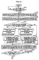
- Step S101 it is determined whether a given restart condition is satisfied (for example, whether an accelerator pedal operation for starting a stopped vehicle is performed; whether a battery voltage is less than a predetermined value; or whether an air conditioner is activated) (Step S101). If the determination in Step S101 is NO, or it is determined that the engine restart condition is not satisfied, the ECU 2 will be kept in a standby state.
- a given restart condition for example, whether an accelerator pedal operation for starting a stopped vehicle is performed; whether a battery voltage is less than a predetermined value; or whether an air conditioner is activated
- Step S101 determines whether the in-cylinder temperature estimation section 46 is based on the stop position of each piston 13 detected by the piston position detection section 45.
- respective air quantities in the compression-stroke cylinder 12C and the expansion-stroke cylinder 12A are calculated (Step S103). Specifically, a volume of the combustion chamber in each of the compression-stroke and expansion-stroke cylinders 12C, 12A can be calculated from the stop position of the corresponding piston 13.
- a flesh air quantity can be derived from the calculated combustion chamber volume, because the engine has several cycles in the period from the interruption of the fuel injection to the engine stop to allow the cylinders including the expansion-stroke cylinder 12A to be filled with flesh air, and an in-cylinder pressure in each of the compression-stroke and expansion-stroke cylinders 12C, 12A becomes approximately equal to atmosphere pressure after the engine stop.
- Step S104 it is determined whether the piston stop position in the compression-stroke cylinder 12C is located at a position falling within the adequate stop range (of 60 to 80°CA before TDC or BTDC 60 to 80°CA) and relatively close to the bottom dead center (BDC) In the compression-stroke cylinder 12C (Step S104),
- Step S104 determines whether the compression-stroke cylinder 12C contains a relatively large air quantity. If the determination in Step S104 is YES, and it Is determined that the compression-stroke cylinder 12C contains a relatively large air quantity, the process will advance to Step S105.
- Step 105 a given amount of fuel is injected into the compression-stroke cylinder 12C containing the air quantity calculated in Step S103 to form therein an air-fuel mixture with an air-fuel ratio having ⁇ (excess air ratio) > 1 (e.g. air-fuel ratio: about 20) (initial or primary fuel injection).
- This air-fuel ratio is determined using a first air-fuel ratio map M1 for the primary fuel injection in a compression-stroke cylinder, which is predetermined with respect to each piston stop position.
- the lean air-fuel ratio having A > 1 can prevent combustion energy for the reverse rotation operation from being excessively produced, so as to avoid the risk of excessive movement in the reverse rotation direction (the piston 13 of the compression-stroke cylinder 12C moved in the reverse rotation toward the BDC direction passes through the BDC and reached an intake stroke), even if the compression-stroke cylinder 12C contains a relatively large air quantity.
- This air-fuel ratio is determined using a second air-fuel ratio map M2 for the primary fuel injection in a compression-stroke cylinder.
- Step S107 the process advances to Step S107, at a time (Time t10 in FIG. 11) after the lapse of a given time predetermined in consideration of a period of time required for vaporization of the fuel injected into the compression-stroke cylinder 2C through the primary fuel injection, the obtained air-fuel mixture in the cylinder 12C is ignited. Subsequently, it is determined whether the pistons 13 are moved, based on whether at least one edge (rising (up) or falling (down) edge) of detection signals from the crank angle sensors 30, 31 is detected within a given time after the ignition (Step S108).
- Step S109 If the determination in Step S108 is NO or it is determined that the pistons 13 are not moved due to misfire, an additional ignition will be performed for the compression-stroke cylinder 12C (Step S109).
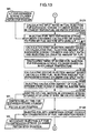
- a split ratio [the ratio between a first (initial) injection and a second (last) injection] In a split fuel injection for the expansion-stroke cylinder 12A is calculated based on and the in-cylinder temperature estimated in Step S102 and the piston stop position (Step S121).
- the percentage of the last injection is set at a larger value as the piston stop position in the expansion-stroke cylinder 12A is located closer to the BDC, and the in-cylinder temperature is higher.
- This total air-fuel ratio is determined using an air-fuel ratio map M3 for the expansion-stroke cylinder 12A, predetermined with respect to each stop position of the piston 13.
- an initial (first) fuel injection amount for the expansion-stroke cylinder 12A is calculated based on the total fuel injection amount calculated in Step S122 and the split ratio calculated in Step S121, and the calculated amount of fuel is injected (Step S123).
- a last (second) fuel injection timing for the expansion-stroke cylinder 12A is calculated based on the in-cylinder temperature estimated in Step S102 (Step S124).
- This second injection timing is set to be in a period where the in-cylinder air is being compressed after the piston 13 starts moving toward the TDC (reverse rotation of the engine crankshaft), so as allow latent heat of vaporization of the injected fuel to effectively reduce a compression pressure (or allow the piston 13 to be moved toward the TDC as close as possible.
- the second injection timing is also set to maximize a period of time for allowing the fuel in the second injection to be vaporized before an ignition timing therefor.
- a last (second) fuel injection amount for the expansion-stroke cylinder 12A is calculated based on the total fuel injection amount for the expansion-stroke cylinder 12A calculated in Step S122 and the split ratio calculated in Step S121 (Step S125), and this fuel is injected at the second injection timing calculated in Step S124 (Step 126).
- Step S127 After the second fuel injection to the expansion-stroke cylinder 12A, the obtained air-fuel mixture is ignited after the lapse of a given delay time-period (at Time t11 in FIG. 11) (Step S127).
- This delay time-period is determined using an ignition map M4 for the expansion-stroke cylinder 12A, predetermined with respect to each stop position of the piston 13.
- the rotation direction of the engine crankshaft is changed from the reverie rotation to the normal rotation.
- the piston 13 of the compression-stroke cylinder 12C is moved toward the TDC to start compressing in-cylinder gas (burnt gas through the combustion induced by the ignition in Step S107).
- a secondary fuel injection is performed for the compression-stroke cylinder 12C (Step S128).
- the amount of fuel in the secondary fuel injection is determined to allow a total air-fuel ratio based the sum of respective fuel injection amounts in the primary and secondary fuel injections to be richer (e.g. about 6) than a combustible air-fuel ratio (lower limit: 7 to 8), by use of an air-fuel ratio map M5 for the secondary fuel injection, predetermined with respect to each stop position of the piston 13.
- a compression pressure around 1TDC in the compression-stroke cylinder 12C can be reduced to allow the piston 13 to readily pass through this 1TDC.
- the secondary fuel injection to the compression-stroke cylinder 12C is intended only to reduce the in-cylinder compression pressure. That is, no ignition for inducing combustion is executed (the obtained air-fuel mixture richer than a combustible air-fuel ratio causes no self-ignition).
- the resulting unburnt fuel will be purified through the reaction with oxygen stored in the catalyst of the catalytic converter 37 in the exhaust passage 22.
- the fuel injected by the secondary fuel injection for the compression-stroke cylinder 12C Is not burnt.
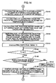
- combustion subsequent to the first combustion in the expansion-stroke cylinder 12A is induced in the intake-stroke cylinder 12D.
- Energy of the first combustion in the expansion-stroke cylinder 12A is partly used as energy required for the piston 13 of the intake-stroke cylinder 12D to pass through 2TDC. That is, the energy of the first combustion in the expansion-stroke cylinder 12A is used as both energy required for the piston 13 of the compression-stroke cylinder 12C to pass through the 1TDC and energy required for the piston 13 of the intake-stroke cylinder 12D to pass through the 2TDC.
- Step S140 an air density in the intake-stroke cylinder 12D is estimated to calculate an air quantity therein In accordance with the estimated value. Then, in Step S102, based on the in-cylinder temperature estimated in Step S102, an air-fuel ratio correction value for preventing self-Ignition is calculated (Step S141). Specifically, the occurrence of self-ignition leads to combustion generating an undesirable force (counter torque) pushing back the piston 13 toward the BDC before reaching the 2TDC. This undesirably causes additional consumption of the energy for passing through the 2TDC. Thus, the air-fuel ratio is corrected to a leaner value to prevent the occurrence of self-ignition.
- Step S142 based on the air quantity in the intake-stroke cylinder 12D calculated in Step S140, and an air-fuel ratio corrected by the air-fuel ratio correction value calculated in Step S141, a fuel injection amount for the intake-stroke cylinder 12D is calculated (Step S142).
- Step S143 the calculated amount of fuel is injected into the intake-stroke cylinder 12D.
- This fuel injection is executed at a delayed timing set in the last phase of a compression stroke to allow latent heat of vaporization of the fuel to effectively reduce a compression pressure (or allow the energy require for passing through the 2TDC to be reduced) (Step S143).
- This delay time-period is calculated based on the lapsed time after completion of the automatic engine stop control (automatic stop period of the engine), the intake temperature, the engine coolant temperature, etc.
- the start-adequacy evaluation section 49 of the ECU 2 calculates the inspection time on the basis of a reference time defined by the time when the edge of the detection signals from the crank angle sensors 30, 31 in Step S108 (Step S145).
- Step S146 it is determined whether the engine speed (inspection engine speed) Ne at Time t12 in FIG. 11 is less than a given required engine speed (e.g. 200 rpm) (Step S146).
- the inspection engine speed is equal to or greater than the required engine speed in this determination, as in the characteristic curve indicated by the broken line in FIG. 11, it can be considered that the piston of the Intake-stroke cylinder will be moved beyond the 2TDC.
- the ignition timing in the intake-stroke cylinder Is retarded or delayed after the 2TDC (Step S148).
- the above process makes it possible to reduce the compression pressure in the intake-stroke cylinder 12D before the 2TDC so as to allow the piston of the intake-stroke cylinder 12D to be reliably moved beyond the 2TDC, and to Induce combustion in the intake-stroke cylinder 12D after passing of the 2TDC so as to generate a torque in the normal rotation direction.
- Step S146 if the inspection engine speed is less than the required engine speed, as in the characteristic curve indicated by the solid line in FIG. 11, the process will advance to a simultaneous starter-motor drive subroutine, and Step S148 will be skipped.
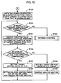
- the start control section 48 waits until Time t13 when the engine speed Ne becomes lower and initially reaches 0 (zero) is detected by the crank angle sensor 30 (Step S1471).
- the start-adequacy evaluation section 49 defines this Time t13 as an assist-control reference time for performing a calculation related to an assist control on the basis thereof (Step S1472).
- Step S1473 a period of time between Time t13 and a zero-speed Time tp when the engine speed Ne becomes 0 (zero) by a transition in rotation direction of the engine crankshaft 3 from the reverse direction occurring at Time t13 to the normal direction is calculated. Further, based on the calculated zero-speed Time tp an engagement time range Ts for the engagement with the starter motor 36 is calculated (Step S1474).
- This engagement time range Ts is determined based on data of product specifications of the starter motor 36 employed in this embodiment. The data is pre-stored in a storage area of the ECU 2.
- the engine starting system is designed such that, when the ring gear 35 is stopped, the pinion gear 36b is driven by driving motor 36a at about 60 rpm in a direction opposite to that in which the ring gear 35 is to be rotated, and brought into engagement with the ring gear 35.
- the engagement time range is set in a range where the engine speed Ne is increased from 0 (zero) to 60 rpm.
- a driving delay time-period Tdy in the starter motor 36 is calculated based on the buttery voltage (Step S1475).
- the engine starting system according to this embodiment is designed such that the pinion gear 36b is brought into engagement with the ring gear 35, in the state when it is rotated by driving motor 36a in a direction opposite to that in which the ring gear 35 is to be rotated.
- a certain time lag i.e. driving delay time-period Tdy
- Step S1475 Time t out is calculated in consideration of the driving delay time-period Tdy.
- the start control section 48 determines whether a lapsed time from Time t13 reaches Time t out (Step S1477). Upon reaching t out , the drive signal is entered into the driving motor 36a of the starter motor 36 (Step S1478). Thus, the pinion gear 36b of the starter motor 36 is driven by the driving motor 36a, and bought Into engagement with the ring gear 35. Then, the crankshaft 3 is assisted by a driving force from the starter motor 36, and the process returns to the main routine.
- the start control section 48 is designed to define the Time t13 when the engine speed Ne becomes lower and initiatiy reaches 0 (zero), in accordance with the engine speed Ne signal detected by the crank angle censor 30, the Time t13 may be defined based on a time of a transition in rotation direction of the crankshaft 3 to be detected by the pair of crank angle sensors 30, 31, or a signal representing a time when the engine crankshaft has a transition in rotation direction from the normal direction to the reverse direction, which can be obtained from respective detection signals of the pair of crank angle sensors 30, 31.
- engine restart control may be shifted to a normal engine control after the passing of 2TDC by means of the direct start control or the combination of the direct start control and the starter motor, an additional control for suppressing engine speed surging is performed in this embodiment.
- engine speed surging herein means a phenomenon that an engine speed is increased excessively and rapidly after the first combustion in the intake-stroke cylinder 12D. The sharp increase in engine speed due to the engine speed surging undesirably causes acceleration shock and driver's uncomfortable feel.
- the intake pressure (pressure on the downstream side of the throttle valve 23) is approximately equal to atmosphere pressure during the automatic stop period, and thereby combustion energy in each of the cylinders 12A to 12D just after engine start (after the first combustion in the intake-stroke cylinder 12D) temporarily becomes greater than that in normal idling to cause the engine speed surging.
- a control for setting an air-fuel ratio at a lean value ( ⁇ > 1) and/or delaying an ignition timing depending on the temperature of the catalytic converter 37 to suppress the engine speed surging is performed In the subsequent Steps S149 to S159.
- the alternator 28 is firstly activated to generate power (Step S149). Under the control of the alternator output control section 44 of the ECU 2, a target output current in this power generation Is set at a value slightly greater than a normal value. This power generation of the alternator 28 provides an increased load onto the crankshaft 3 (engine load) to suppress engine speed surging.
- Step S150 it is determined whether the intake pressure detected by the Intake pressure sensor 26 is greater than that during a normal idling without the automatic engine stop control. If the determination in Step S150 is YES, or the current condition is liable to cause engine speed surging, the opening of the throttle valve 23 will be reduced to be less than that during the normal idling (Step S151) to suppress the amount of combustion energy to be produced.
- Step S152 it is determined whether the catalyst of the catalytic converter 37 in the exhaust passage 22 has a temperature equal to or less than an activation temperature thereof (Step S152).
- the amount of combustion energy to be produced can be further suppresses by the delayed ignition timing.
- Step S152 If the determination in Step S152 is made as NO, the target air-fuel ratio is set at a lean value or ⁇ > 1 and fuel is injected (Step S158). In this case, the fuel is burnt without delaying the ignition timing (Step S159). This lean combustion makes it possible to achieve reduced fuel consumption and suppress the amount of combustion energy to be produced.
- Step S154 or S159 the process returns to Step S150, the process will be repeated until the determination at Step S150 is made as NO. If the determination at Step S150 is made as NO, or the current condition has no risk of causing engine speed surging, the engine control including the alternator output control will return to the normal control (Step S160).
- the success/failure or adequacy of the so-called direct start is determined based on the engine speed Ne at Inspection Time t12.
- the starter motor 36 will not be always driven. This can contributes to energy saving as compared the conventional technique disclosed in the aforementioned Publication 2.
- the starter motor 36 is driven after the engine crankshaft has the transition in rotation direction from the reverse direction to the normal direction and in a time range near to the zero-speed Time tp. This makes it possible to assist the engine start in the stage where a load to be imposed on the starter motor 36 is minimum.
- the starter motor 36 can have reduced load and enhanced reliability. In addition, this can contribute to enhancement in durability of the starter motor 36 itself.
- the starter motor 36 includes the pinion gear 36d engageable with the ring gear 35 associated with the engine, and the start control section 48 is operable, after the engine crankshaft has the transition in rotation direction from the reverse direction to the normal direction, to determine the timing of engagement with the pinion gear 36a in the time range near to the zero-speed Time tp, and to allow the assist operation based on the starter motor 36 to be initiated after the engagement between the pinion gear 36d and the ring gear 35.
- the crank angle sensors 30, 31 serving as the rotational speed detection means are operable to send to the start control section 48 an assist-control reference Time t13 defined by a time when the engine speed is lowered from the inspection engine speed Ne to zero, and the start control section 48 is operable to calculate the zero-speed Time tp in accordance with the received assist-control reference Time t13 and determine the time range of the engagement between the pinion gear 36d and the ring gear 35 in accordance with the calculated zero-speed Time tp.
- the start control section 48 is operable to calculate the driving delay time-period Tdy in the starter motor 36, and determine the an output time of the drive signal in accordance with the calculated driving delay time-period Tdy in such a manner as to allow the drive signal to be output at a time earlier than the zero-speed Time tp. That is, the driving delay time-period Tdy in the starter motor 36 Is Included in one of control parameters.
- the starter motor 36 has a time lag between the receiving of the drive signal and the driving of the engine, an intended assist initiation time can be reliably set. This makes it possible to allow tolerance of the driving delay time-period in the starter motor 36 to be relaxed so as to provide applicability of various types of alternators and contribute to cost reduction.
- the start-adequacy evaluation means may be operable to estimate a time when the expansion-stroke cylinder 12A first reaches a top dead center in an exhaust stroke, so as to defined the estimated time as Inspection Time t12, and evaluate the adequacy of the engine restart in accordance with an inspection engine speed Ne defined by the engine speed detected at the inspection Time t12 and received from the rotational speed detection means.
- the inspection time t12 can be estimate relatively accurately. This has an advantage of being able to accurately evaluate the adequacy of the inspection engine speed Ne and detect the inspection engine speed Ne readily and accurately so as to achieve enhanced control accuracy.
- the control In combination with the assist operation using the starter motor 36 may also be performed, but not shown in the above embodiment, when a given condition is not satisfied (for example, when the piston stop position is not in the adequate range), and/or when the engine speed does not reach a given value within a given period of time after the initiation of the engine restart control.
- the start assets device While it is preferable to use the starter motor 36 having the pinion gear engageable with the ring gear fixed to the flywheel of the engine, the start assets device to be used in the present invention is not limited to this type designed to output a driving power from the pinion gear, but may be any other suitable type, such as a belt type.
- the automatic engine stop control to be used in the present invention is not limited to the control described in the above embodiment, but may be appropriately arranged. However, in order to achieve an enhanced engine restart performance, it is desirable to control in such a manner that the piston 12 of the expansion-stroke cylinder 12A is stopped at a position slightly close to the BDC relative to the midpoint of the stroke (in the compression-stroke cylinder 12C: a position slightly close to the TDC relative to the midpoint of the stroke).
Landscapes
- Engineering & Computer Science (AREA)
- Chemical & Material Sciences (AREA)
- Combustion & Propulsion (AREA)
- Mechanical Engineering (AREA)
- General Engineering & Computer Science (AREA)
- Control Of Vehicle Engines Or Engines For Specific Uses (AREA)
- Combined Controls Of Internal Combustion Engines (AREA)
- Output Control And Ontrol Of Special Type Engine (AREA)
Abstract
Disclosed is an engine starting system for restarting an automatically stopped engine in
such a manner as to rotate a crankshaft in a reverse rotation direction and then to rotate the
crankshaft In a reverse rotation direction. The engine starting system comprises
start-adequacy evaluation means operable to evaluate the adequacy of the engine start in
accordance with an inspection engine speed defined by an engine speed Ne at an inspection
time t12 which is set at a time when a given time lapses from initiation of the combustion in a
cylinder in the state after being stopped in a compression stroke. The engine restart system is
designed such that, when the start-adequacy evaluation means determines that the inspection
engine speed is less than an engine speed required for normally restarting the engine, a start
assist device is driven at a given timing. The engine starting system of the present invention
can automatically stop an engine to improve fuel consumption, and quickly restart the engine in
a manner for minimizing the frequency in use of a starter motor and/or needless combustion to
facilitate energy saving.
Description
The present invention relates to an engine starting system, and more particularly to an
engine starting system for automatically stopping an engine in an operating state, such as idling
state, when a given automatic stop condition is satisfied, and then restarting the engine when a
given restart condition is satisfied.
In late years, as part of measures for reductions In fuel consumption and CO2 emissions,
efforts have been made to develop an engine staring system intended to automatically stop an
engine in an operating state, such as an idling state, and then automatically restart the engine
upon satisfaction of a restart condition, e.g. a driver's action for vehicle start. From a technical
standpoint, there has been known one technique of supplying fuel to a cylinder which is in an
expansion stroke position after an engine is stopped, and inducing combustion In the cylinder to
start the engine by means of the resulting combustion energy, as disclosed, for example, in the
following Publications 1 and 2.
WO 01/44636 A2 [Hereinafter referred to as Publication 1]
JP 2002-4985 A1 [Hereinafter referred to as Publication 2]
As measures for achieving a higher success rate in automatically restarting the automatically stopped engine, thePublication 1 further discloses a technique of controlling an exhaust valve
closing timing after an ignition switch is turned off, so as to stop the engine at a given crank
angle.
WO 01/44636 A2 [Hereinafter referred to as Publication 1]
JP 2002-4985 A1 [Hereinafter referred to as Publication 2]
As measures for achieving a higher success rate in automatically restarting the automatically stopped engine, the
It is also known that, when an engine cannot be adequately started only by combustion in a
cylinder which is in an expansion stroke position after the engine is stopped, a starter motor
(motor for starting an engine) is additionally driven to provide enhanced reliability of engine
starting, as disclosed, for example, In the Publication 2.
The engine staring system as disclosed in the Publication 2 is designed to unexceptionally
drive the starter motor when an engine start condition is satisfied In the state after an engine is
completely stopped, as clearly described in the paragraph [0023] of the Publication 2. That is,
even if a crankshaft is stopped at a position allowing for the so-called "direct start" (restart based
on only combustion in a cylinder) by use of the control technique as disclosed in the Publication
1, the advantage of this control technique cannot be utilized. Thus, it can be hardly said that
this system is adapted to sufficiently suppress electric power consumption. Moreover, the
system in the Publication 2 is designed such that a fuel is periodically injected into the cylinder in
an expansion stroke, to maintain a given engine speed, during the period from the stop of the
engine through until the engine start condition is satisfied. This control also leads to
consumption of needless fuel.
Further, even if a piston is stopped at a desired phase angle, a success probability of the
so-called "direct start" will not be always 100 %. Thus, when the success of the direct start
cannot be expected, the starter motor has to be promptly activated or driven to quickly start the
engine.
In view of the above circumstances, it is an object of the present invention to provide an
engine starting system capable of automatically stopping an engine to improve fuel consumption,
and quickly restarting the engine in a manner for minimizing the frequency in use of a starter
motor and/or needless combustion to facilitate energy saving.
The present invention provides an engine starting system for use in a vehicle equipped
with a 4-stroke engine where one power cycle consisting of intake, compression, expansion and
exhaust strokes is produced by two reciprocating motions of a piston. The engine includes:
fuel supply means for supplying fuel into each of a plurality of cylinders; a plurality of spark plugs
provided in the cylinders, respectively; rotational speed detection means for detecting an engine
speed; and a start assist device adapted to drive a crankshaft of the engine using a motor. The
engine starting system comprises: automatic stop control means operable, upon satisfaction of
a predetermined automatic engine stop condition, to allow the supply of a fuel for maintaining an
operating state of the engine to be interrupted so as to automatically stop the engine; start
control means operable, upon satisfaction of a restart condition for restarting the automatically
stopped engine, to allow the spark plug of at least the cylinder in the state after being stopped in
an expansion stroke to ignite a fuel supplied into the cylinder and induce combustion in the
cylinder, so as to automatically restart the engine: start-adequacy evaluation means for
evaluating whether the engine start based on the start control means Is adequate; and assist
drive control means operable, when the start-adequacy evaluation means determines that the
engine start based on the start control means is inadequate, to drive the start assist device. In
this engine starting system, the start-adequacy evaluation means Is operable to receive from
said engine speed detection means an inspection engine speed defined by an engine speed
detected at an inspection time which is set at a time when a given time lapses from initiation of
the combustion In the cylinder in the state after being stopped In the compression stroke, and
evaluate the adequacy of the engine start in accordance with the inspection engine speed; and
the assist drive control means is operable, when the start-adequacy evaluation means
determines that the inspection engine speed is less than a given engine speed required for
adequately restarting the engine, to drive the start assist device around a zero-speed time when
the crankshaft has a transition In rotation direction from a reverse direction occurring after an
engine speed is lowered to zero, to a normal direction.
In the present invention, when a given restart condition is satisfied after stop of the engine,
an engine speed is detected at the inspection time. When the engine speed at the inspection
time is less than a given value, it is be determined the so-called direct start fails, and then the
start assist device is driven and associated with the engine having a relative low engine speed,
to assist the restart of the engine.
Preferably, the start assets device includes a starter motor having a pinion gear
engageable with a ring gear fixed to a flywheel of the engine. The starter motor to be used In
the present invention is not limited to the type where a driving power is output from the pinion
gear, but may be any other suitable type, such as a belt type.
In another specific embodiment, the assist drive control means is operable to drive the
start assist device after the crankshaft has the transition in rotation direction from the reverse
direction to the normal direction, and In a time range near to the second zero-speed time.
In another specific embodiment, the start assist device includes a pinion gear engageable
with a ring gear provided in the engine, and the assist drive control means is operable to set
around the zero-speed time an engagement time when the pinion gear is brought into'
engagement with the ring gear, and drive the start assist device after completion of the
engagement between the pinion gear and the ring gear.
According to this embodiment, the pinion gear of the start assist device is brought into
engagement with the ring gear after the crankshaft has the transition in rotation direction from
the reverse direction to the normal direction and in a time range near to the second zero-speed
time. Thus, even in the type where the pinion gear is brought into engagement with the ring
gear, in the state when it is rotated in a direction opposite to that of the ring gear crankshaft, the
engagement can be achieved without load onto the start assist device.
In another specific embodiment, the engine speed detection means is operable to send to
the assist drive control means an assist-control reference time defined by a time when an
engine speed is lowered from the inspection engine speed to zero, and the assist drive control
means is operable to calculate the zero-speed time in accordance with the assist-control
reference time and determine a time range of the engagement between the pinion gear and the
ring gear in accordance with the calculated zero-speed time.
According to this embodiment, the calculations for the engagement time can be initiated in
the stage where the start-adequacy evaluation means determines evaluates the necessity of the
start assist device, and quickly determine the engagement time between the pinion gear and the
ring gear.
In another specific embodiment, the assist drive control means is operable to calculate a
driving delay time-period in the start assist device, and determine an output time of a drive signal
In accordance with the calculated driving delay time-period in such a manner as to allow the
drive signal to be output to the start assist device at a time earlier than the zero-speed time.
According to this embodiment, the driving delay time-period in the start assist device is
included in one of control parameters. Thus, even if the start assist device has a time lag
between the receiving of the drive signal and the driving of the engine, an intended assist
initiation time can be reliably set.
In another specific embodiment, the start-adequacy evaluation means is operable, when
the restart of the engine is successfully initiated, to estimate a time when the cylinder in the state
after being stopped in an expansion stroke firstly reaches a top dead center In an exhaust stroke,
so as to define the estimated time as the inspection time, and evaluate the adequacy of the
engine restart in accordance with the inspection engine speed defined by an engine speed
detected at the defined inspection time and received from the rotational speed detection means.
According to this embodiment, when the restart of the engine is successfully initiated, the
inspection time corresponding to the evaluation time for the start-adequacy evaluation means is
set at the time when the cylinder in the state after being stopped in an expansion stroke firstly
reaches a top dead center in an exhaust stroke, This makes it possible to determine the
inspection time in accordance with a phase of the crankshaft corresponding to the inspection
time.
As above, according the present invention, the success/fallure or adequacy of the
so-called direct start is determined based on the engine speed at the inspection time. Thus,
even if the restart control is initiated after stop of the engine, the start assist device will not be
always driven. This can contributes to energy saving as compared the conventional technique
disclosed in the aforementioned Publication 2.
Particularly, in one aspect of the present invention, where the start assist device is driven
after the engine crankshaft has the transition in rotation direction from the reverse direction to
the normal direction and in a time range near to the zero-speed time, the start assist device can
assist the engine start in the stage where a load to be imposed on the start assist device is
minimum. Thus, the start assist device can have reduced load and enhanced reliability. In
addition, this can contribute to enhancement In durability of the start assist device itself.
Further, in another aspect of the present invention, where the start assist device includes
the pinion gear engageable with the ring gear associated with the engine, and the assist drive
control means is operable, after the engine crankshaft has the transition in rotation direction
from the reverse direction to the normal direction, to determine the timing of engagement with
the pinion gear 36a in the time range near to the zero-speed time, and to allow the assist
operation based on the start assist device to be initiated after the engagement between the
pinion gear and the ring gear, the engagement can be achieved without load onto the start assist
device even in the type where the pinion gear is brought into engagement with the ring gear, in
the state when it is rotated by driving motor In a direction opposite to that in which the ring gear
is to be rotated,. This can contribute to enhancement in reliability and durability of the start
assist device.
In still another aspect of the present invention, where the rotational speed detection means
are operable to send to the assist drive control means an assist-control reference time defined
by a time when an engine speed is lowered from the inspection engine speed to zero, and the
assist drive control means is operable to calculate the zero-speed time in accordance with the
received assist-control reference time and determine the time range of the engagement
between the pinion gear and the ring gear in accordance with the calculated zero-speed time,
the load onto the start assist device can be further reduced to contribute to enhancement in
reliability and durability.
In yet still another aspect of the present invention, where the assist drive control means is
operable to calculate the driving delay time-period in the start assist device, and determine the
an output time of the drive signal in accordance with the calculated driving delay time-period In
such a manner as to allow the drive signal to be output at a time earlier than the zero-speed time,
the driving delay time-period in the start assist device is included in one of control parameters.
Thus, even if the start assist device has a time lag between the receiving of the drive signal and
the driving of the engine, an intended assist initiation time can be reliably set. This makes it
possible to allow tolerance of the driving delay time-period in the start assist device to be relaxed
so as to provide applicability of various types of alternators and contribute to cost reduction.
In another further aspect of the present invention, where, when the restating of the engine
is successfully initiated, the start-adequacy evaluation means is operable to estimate a time
when the cylinder in the state after stopped in an expansion-stroke cylinder first reaches a top
dead center in an exhaust stroke, so as to defined the estimated time as the inspection time,
and evaluate the adequacy of the engine restart in accordance with an inspection engine speed
defined by the engine speed detected at the inspection time and received from the rotational
speed detection means, the inspection time can be estimate relatively accurately. This has an
advantage of being able to accurately evaluate the adequacy of the inspection engine speed
and detect the inspection engine speed readily and accurately so as to achieve enhanced
control accuracy.
FIGS. 1 and 2 schematically show the structure of a four-stroke spark-ignition internal
combustion engine having an engine starting system according to one embodiment of the
present invention. This engine comprises an engine body 1 including a cylinder head 10 and a
cylinder block 11, and an engine control ECU (electronic control unit) 2. The engine body 1
has four cylinders (a cylinder # 1 or 12A, a cylinder # 2 or 12B, a cylinder # 3 or 12C and a cylinder
# 4 or 12D), and a piston 13 connected to a crankshaft 3 is slidably fitted In each of the cylinders
12A to 12D to define a combustion chamber 14 thereabove.
In this embodiment, a cylinder which is or was in a compression stroke during an
after-mentioned automatic engine stop control, and a cylinder which is or was in an expansion
stroke during the automatic engine stop control, are referred to, respectively, as
"compression-stroke cylinder" and "expansion-stroke cylinder" (in the same way, a cylinder
which is or was in an intake position during the automatic engine stop control, and a cylinder
which is or was in an exhaust stroke during the automatic engine stop control, are referred to,
respectively, as "intake-stroke cylinder" and "exhaust-stroke cylinder"). However, as used In
the specification, each of these terms does not fixedly mean a specific cylinder, but expediently
expresses each cylinder in accordance with the stroke of the cylinder during, or just before the
completion of, the automatic engine stop control.
The combustion chamber 14 in each of the cylinders 12A to 12D has a top wall portion
provided with a spark plug 15 whose tip is exposed to the combustion chamber 14. Each of the
spark plugs 15 is electrically connected to an ignition device 27 for activating the corresponding
spark plug 15 to generate an electric spark therein. Further, a fuel injection valve 16 is
attached to a side wall portion of the combustion chamber 14 in each of the cylinders 12A to 12D
to inject fuel directly into the combustion chamber 14, This fuel injection valve 16 internally
having a needle valve (not shown) and a solenoid (not shown) is designed such that the
solenoid is driven for a period of time corresponding to a pulse width of a pulse signal entered
therein from a fuel injection control section 41 of the ECU 2, to open the needle valve so as to
inject fuel in an amount proportional to the valve open period, toward and around electrodes of
the spark plug 15.
The combustion chamber 14 in each of the cylinders 12A to 12D also has an upper wall
portion formed with an intake port 17 and an exhaust ports 18 each extending to open into the
combustion chambers 14. The Intake port 17 is equipped with an intake valve 19, and each of
the exhaust ports 18 is equipped with an exhaust valve 20. The intake valve 19 and the
exhaust valve 20 are designed to be driven by a valve operating mechanism including a
camshaft (not shown), so that respective opening/closing timings of the intake and exhaust
valves 19, 20 in the cylinders 12A to 12D are set to allow a four-stroke combustion or power
cycle to be performed in the cylinders 12A to 12D with a given phase differences therebetween.
The intake port 17 and the exhaust port 18 are in fluid communication with an intake
passage 21 and an exhaust passage 22, respectively. As shown in FIG. 2, a downstream
portion of the intake passage 21 on the side closer to the intake port 17 is formed as an intake
manifold with four independent passages 21 a corresponding to the cylinders 12A to 12D, and
respective upstream ends of the intake manifold passages 21 a are in fluid communication with a
surge tank 21 b. An upstream portion of the intake passage 21 relative to the surge tank 21 b is
formed as a common intake passage 21 c which is provided with a throttle valve 23 designed to
be driven by an actuator 24. Further, an air-flow sensor 25 for detecting an intake-air flow rate
and an intake-air temperature sensor 29 for detecting an intake-air temperature are disposed on
the upstream side of the throttle valve 23, and an intake pressure sensor 26 for detecting an
intake pressure (negative pressure) is disposed on the downstream side of the throttle valve 23.
As shown in FIGS. 1 and 2, a portion of the exhaust passage 22 on the downstream side of
an exhaust manifold for collectively receiving exhaust gas from the cylinders 12A to 12D is
provided with a catalytic converter 37 for purifying the exhaust gas. For example, the catalytic
converter 37 contains a three-way catalyst which exhibits a significantly high conversion rate of
HC, CO and NOx when an air-fuel ratio of exhaust gas is close to a theoretical value. More
specifically, the three-way catalyst has an ability of absorbing and storing oxygen therein in an
oxygen-rich atmosphere or when exhaust gas has a relatively high oxygen concentration, and
releasing the stored oxygen to induce a reaction with HC, CO, etc. when exhaust gas has a
relatively low oxygen concentration. The catalyst to be used for the catalytic converter 37 is not
limited to the three-way catalyst, but may be any other suitable catalyst having the
aforementioned oxygen absorbing/storing ability, for example, the so-called lean NOx catalyst
capable of purifying NOx in an oxygen-rich atmosphere.
An alternator 28 is attached to the engine body 1 and connected to the crankshaft 3
through a timing belt or the like. This alternator 28 is internally provided with a regulator circuit
28a for controlling a current to be applied to a field coil (not shown) thereof to regulate an output
voltage so as to adjust an output, and designed to be controlled according to a control signal
sent from the ECU 2 to the regulator circuit 28a so as to generate an output in proportion, for
example, to an electric load of a vehicle and a voltage of a battery mounted on the vehicle.
The engine is provided with a pair of first and second crank angle sensors 30, 31 for
detecting a rotational angle of the crankshaft 3. The first crank angle sensor 30 is operable to
generate a detection signal for use in detecting an engine speed. Further, the first and second
crank angle sensors 30, 31 are arranged to generate detection signals having a phase lag, and
these detection signals are used to detect a rotation direction and a rotational angle of the
crankshaft 3, as described later in more detail.
The engine body 1 is also provided with a cam angle sensor 32 for detecting a specific
rotational position of the camshaft to discriminate the cylinders from each other, and a coolant
temperature sensor 33 for detecting an engine coolant temperature. Further, an
accelerator-pedal angle sensor 34 is associated with an accelerator pedal mounted on the
vehicle body to detect an accelerator-pedal angle corresponding to a displacement of the
accelerator pedal caused by a driver's operation.
A flywheel (not shown) and a ring gear 35 fixed to the flywheel are fixedly attached to the
crankshaft 3 concentrically with respect to the rotational axis of the crankshaft 3. The ring gear
35 is an input member for a starter motor 36 serving as a start assist device, and designed to be
engageable with an after-mentioned pinion gear 36d of the starter motor 36.
Referring to FIG. 3, the starter motor 36 includes a driving motor 36a, an
electromagnetically- driven plunger 36b disposed parallel to the driving motor 36a, and a pinion
gear 36d which is slidably fitted on an output shaft of the driving motor 36a in a non-rotatable
manner relative to the output shaft, and adapted to be reciprocatingly moved along the output
shaft by the plunger 36b through a shifting lever 36c. More specifically, in an engine restart
control for automatically restarting the engine, the plunger 36b is operable to move the pinion
gear 36d from a standby position indicated by the solid lines in FIG. 3 to an engagement position
indicated by the two-dot chain lines in FIG. 3 and bring the pinion gear 36d Into engagement
with the ring gear 35 so as to rotatively drive the crankshaft 3 to restart the engine.
The pinion gear 36d of the starter motor 36 employed in this embodiment has helically
twisted teeth. Further, in order to facilitate the engagement with the ring gear 35, the starter
motor 36 is designed such that, when the ring gear 35 stops, the pinion gear 36d is rotated at a
speed of about 60 rpm in a direction opposite to a direction in which the ring gear 35 is to be
rotated, and brought into engagement with the ring gear 35.
Referring to FIG. 1, the ECU 2 is a control unit for generally controlling operations of the
engine. The engine starting system according to this embodiment is designed to perform a
control mode (idling stop mode) for interrupting (cutting) fuel to be injected to the cylinders 12A
to 12D upon satisfaction of a predetermined automatic engine stop condition to automatically
stop the engine, and then automatically restarting the engine upon satisfaction of a
predetermined restart condition, e.g. for example, a driver's operation of the accelerator pedal.
The following description about the ECU 2 will be made with the focus on this idling stop mode.
In response to receiving respective detection signals from the air-flow sensor 25, the intake
pressure sensor 26, the intake-air temperature sensor 29, the crank angle sensors 30, 31, the
cam angle sensor 32, the coolant temperature sensor 33 and the accelerator-pedal angle
sensor 34, the ECU 2 is operable to generate and send drive signals, respectively, to the fuel
injection valves 16, the actuator 24 of the throttle valve 23, the ignition device 27, the regulator
circuit 28a of the alternator 28, and the starter motor 36. The ECU 2 functionally includes a fuel
injection control section 41, an ignition control section 42, an intake-air flow-rate control section
43, an alternator output control section 44, a piston position detection section 45, an in-cylinder
temperature estimation section 46, an automatic stop control section 47, a start control section
48, a start-adequacy evaluation section 49, an air-fuel ratio control section 50 and a catalyst
temperature estimation section 52.
The fuel injection control section 41 serves as fuel injection control means for setting a fuel
injection timing and a fuel injection amount in each fuel injection timing, and sending a control
signal representing them to the fuel injection valves 16. Particularly in this embodiment, a split
injection technique is used to supply a fuel for inducing a first combustion in an expansion-stroke
cylinder during the engine restart control, as described later in more detail. The fuel injection
control section 41 is also operable to set split injection timings and a fuel split ratio.
The ignition control section 42 is operable to set a suitable ignition timing for each of the
cylinders 12A to 12D, and send an ignition signal to each of the ignition devices 27.
The intake-air flow-rate control section 43 is operable to set a suitable intake-air flow rate
for each of the cylinders 12A to 12d, and send a throttle opening signal corresponding to the
intake-air flow rate to the actuator 24 of the throttle valve 23. Particularly in this embodiment,
during the automatic engine stop control, the opening of the throttle valve 23 is controllably
adjusted to allow the piston 13 to be stopped at a position falling within an adequate range for
restart of the engine, as described later in more detail. Thus, the intake-air flow-rate control
section 43 is also operable to adjust the opening of the throttle valve 23 for this purpose,.
The alternator output control section 44 is operable to set a desired target output of the
alternator 28, and send a drive signal corresponding to the target output to the regulator circuit
28a. Particularly in this embodiment, during the automatic engine stop control, the output of
the alternator 28 is controllably adjusted to change a load onto the crankshaft 3, so as to allow
the piston 13 to be stopped at a position falling within an adequate range for restart of the engine,
as described later in more detail. Thus, the alternator output control section 44 is also operable
to adjust the output of the alternator 28 for this purpose. Further, during the engine restart
control, the alternator output control section 44 is operable to allow the alternator 28 to generate
a slightly larger output than that in a normal operation so as to increase an engine load to
prevent the occurrence of surging (excessively rapid increase in engine speed).
The piston position detection section 45 is operable to detect a piston position in
accordance with respective detection signals of the crank angle sensors 30, 31. A crank
position and a crank angle (°CA) correspond one-to-one with one another. Thus, in this
specification, a piston position is indicated by a crank angle as in a common practice. In this
embodiment, an air quantity in each of the expansion-stroke and compression-stroke cylinders
is calculated based on each piston position of the cylinders during the automatic engine stop
control to control combustion in each cylinder in accordance with the calculated air quantity, as
described later In more detail.
The in-cylinder temperature estimation section 46 serves as in-cylinder temperature
estimation means for estimating an in-cylinder air temperature in each of the cylinders 12A to
12D in accordance with an engine-coolant temperature detected by the coolant temperature
sensor 33, an intake-air temperature detected by the intake-air temperature sensor 29 or the like
and by use of a map experimentally prepared in advance or the like. Particularly In this
embodiment, during the engine restart control, an in-cylinder temperature is estimated in
consideration of an engine stop time, or a lapsed time after stop of the engine, to perform the
combustion control in accordance with the estimated value, as described later in more detail.
The automatic stop control section 47 serves as automatic stop control means for allowing
the fuel injection to be interrupted upon satisfaction of a given engine stop condition during idling,
so as to automatically stop the engine, as described later in more detail.
The start control section 48 serves as start control means for allowing the automatically
stopped engine to be automatically restarted upon satisfaction of an engine restart condition.
During the engine restart control, if the stop position of each piston 13 falls within an
after-mentioned specific range (adequate range), a certain amount of fuel is injected to at least
an expansion-stroke cylinder In the state after stop of the engine, and ignited to induce
combustion therein. In this embodiment, an initial combustion is induced in a
compression-stroke cylinder in the state after stop of the engine to move the piston 13 of the
compression-stroke cylinder downward, whereby the piston of an expansion-stroke cylinder is
moved upward to provide an increased in-cylinder pressure therein. Then, a certain amount of
fuel is injected into the expansion-stroke cylinder, and ignited to induce combustion therein.
That is, during the automatic engine restart control, when the piston stop position falls within an
after-mentioned adequate range, the engine crankshaft is reversely rotated in the initial stage of
the automatic engine restart control, and then normally rotated, In this embodiment, the start
control section 48 also serves as assist drive control means.
The start-adequacy evaluation section 49 serves as start-adequacy evaluation means for
evaluating the adequacy of engine restart by receiving Inputs from the piston position detection
section 45 and the sensors 30, 31 serving as an engine speed detection section, and using an
inspection engine speed defined by an engine speed detected at Inspection Time t12 (see FIG.
11) set after the lapse of a given time from initiation of the combustion in the expansion-stroke
cylinder.
The air-fuel ratio control section 50 serves as air-fuel ratio control means for calculating an
air-fuel ratio, and determine a fuel amount to be distributed by the fuel injection control section
41 and an intake-air flow-rate to be controlled by the intake-air flow-rate control section 43.
The catalyst temperature estimation section 52 serves as catalyst temperature estimation
means for estimating a temperature of the catalytic converter 37 in accordance with an intake-air
temperature detected by the intake-air temperature sensor 29 or the like and by use of a map
experimentally prepared in advance or the like. Particularly in this embodiment, during the
engine restart control, the catalyst temperature estimation section 52 is operable to estimate a
temperature of the catalytic converter 37 so as to allow the fuel injection and the combustion
control to be performed in accordance with the estimated value, as described later In more
detail.
In the idling stop mode based on the above ECU 2, the engine restart control is performed
as follows. Initially, combustion is induced in the compression-stroke cylinder to move the
piston 13 of the compression-stroke cylinder downward so as to reversely rotate the crankshaft
3. Thus, the piston 13 of the expansion-stroke cylinder is moved upward (closer to a top dead
center (TDC)) to compress air (air-fuel mixture after the fuel injection) in the expansion-stroke
cylinder. In this state, the air-fuel mixture is ignited and burnt to give a driving torque in a
normal rotation direction to the crankshaft 3 so as to restart the engine.
In order to adequately restart the engine only by igniting a fuel injected into a specific one
of the cylinders without using the starter motor 36 or the like, it is required to ensure sufficient
combustion energy to be obtained from combustion of an air-fuel mixture in the
expansion-stroke cylinder so as to allow the piston of another cylinder (compression-stroke and
intake-stroke cylinders in this embodiment) which will reach a TDC in a compression stroke
(compression TDC) subsequently to the piston of the expansion-stroke cylinder, to pass through
the compression TDC against a compressive reaction force therein. Thus, a sufficient quantity
of air should be ensured in the expansion-stroke cylinder.
As shown in FIG. 4(a), the respective pistons 13 of the compression-stroke and
expansion-stroke cylinders are moved in opposite directions because these cylinders are out of
phase by 180°CA.
If the piston 13 of the expansion-stroke cylinder is located on the side of a bottom dead
center (BDC) relative to a stroke midpoint, the expansion-stroke cylinder can have an increased
air quantity to obtain sufficient combustion energy, as shown in FIG. 4(b). However, if the
piston 13 of the expansion-stroke cylinder is located at a position excessively close to the BDC,
an air quantity in the compression-stroke cylinder will be excessively reduced to cause
difficulties in sufficiently obtaining combustion energy for reversely rotating the crankshaft 3 in
the initial combustion.
In contrast, if the piston 13 of the expansion-stroke cylinder can be stopped at a position
falling within a given range R slightly closer to the BDC relative to the stroke midpoint where a
crank angle after the compression TDC is 90°CA, for example, a range R where a crank angle
after the compression TDC is in the range of 100 to 120°CA, a given air quantity will be ensured
in the compression-stroke cylinder. This allows the initial combustion to provide combustion
energy to the extent capable of reversely rotating the crankshaft 3 by a slight angle. In addition,
the larger air quantity contained in the expansion-stroke cylinder makes it possible to sufficiently
generate combustion energy for normally rotating the crankshaft 3 so as to reliably restart the
engine. The above range R will hereinafter be referred to as "adequate stop range R".
The ECU 2 (automatic stop control section 47) performs the following control to allow the
piston 13 to be stopped at a position falling within the adequate stop range R.
FIG. 5 is a time chart showing an engine speed Ne, a boost pressure Bt (intake pressure)
and an opening K of the throttle valve 23, during an automatic stop control based on the
automatic stop control section 47. FIG. 6 is an enlarged diagram of a portion of FIG. 5 just
before and after Time t1, wherein changes in crank angle CA and transitions of the strokes in
each of the cylinders are additionally illustrated. For the sake of simplicity, the following
description will be made on the assumption that the cylinders # 1 or 12A, #2 or 128, #3 or 12C,
#4 or 12D are expansion-stroke, exhaust-stroke, compression-stroke and intake stroke cylinders,
respectively.
At Time t0 when the automatic engine stop condition is satisfied, under the control of the
ECU 2, a target engine speed (idling engine speed when the automatic stop condition is
satisfied) is stabilized at a value slightly greater than a normal idling engine speed in engine
operations without the automatic engine stop control (hereinafter referred to as "normal idling
engine speed). For example, if the engine has the normal idling engine speed set at 650 rpm
(when an automatic transmission is operated in a drive (D) state), the target engine speed will
be set at about 850 rpm (when the automatic transmission is operated in a neutral (N) range).
Further, the opening K of the throttle valve 23 is adjusted to allow the boost pressure Bt to be
stabilized at a relatively high given value (about - 400 mmHg).
Then, at Time t1 when the engine speed Ne becomes stabile at the target engine speed,
under the control of the ECU 2, the fuel injection is interrupted to lower the engine speed Ne.
Further, at Time t1 when the fuel injection is interrupted or in the initial stage of the automatic
engine stop control, the opening K of the throttle valve 23 is increased to allow the intake-air
quantity to be greater than that in an idling operation under the condition that an in-cylinder
air-fuel ratio is set to have an excess air ratio λ of 1 (a minimum intake-air quantity required for
maintaining an engine operation). More specifically, if the engine is operated in homogeneous
combustion just before Time t1 by use of an air-fuel mixture set to have an in-cylinder air-fuel
ratio with an excess air ratio A of 1 or about 1, the opening K of the throttle valve 23 will be
increased (for example, up to about 30 %). If the engine is operated in stratified combustion
just before Time t1 by use of an air-fuel mixture set to have a lean in-cylinder air-fuel ratio, the
opening K of the throttle valve 23 will be maintained as is (at a relatively large opening in the
stratified combustion). FIGS. 5 and 6 show the former case.
As the result of the above control, the boost pressure Bt starts increasing slightly after
Time t1 (if the engine is operated in homogeneous combustion just before Time t1), or keeps at
a relatively high value (if the engine is operated in stratified combustion just before Time t1), to
facilitate scavenging in the combustion chamber.
Further, at Time t1, under the control of the ECU 2, the operation of the alternator 28 is
temporarily stopped. This makes it possible to provide a reduced rotational resistance of the
crankshaft 3 so as to prevent the engine speed Ne from being lowered excessively rapidly.
When the fuel injection is interrupted at Time t1 in the above manner, the engine speed Ne
starts lowering. Then, at Time t2 when it is determined that the engine speed Ne is lowered to
a predetermined reference speed, for example, 760 rpm or less, the throttle valve 23 is closed.
Consequently, the boost pressure Bt starts declining slightly after Time t2 to reduce an intake-air
flow rate to be supplied to each cylinder of the engine. An air sucked during the period
between Time t1 and Time t2, or where the throttle valve 23 is opened, is introduced to the
intake manifold passage 21 a for each cylinder through the common intake passage 21 c and the
surge tank 21 b. Then, the air is sequentially introduced into the cylinders when each of the
cylinders has an intake stroke. In this embodiment, the air is introduced Into the cylinder # 4 or
12D, the cylinder # 2 or 12B, the cylinder # 1 or 12A and the cylinder # 1 or 12C in this order, as
seen in FIG. 6. Thus, according to the aforementioned controls at Time t1 and Time t2, the
cylinder # 1 or 12A (expansion-stroke cylinder) is supplied with a greater air quantity as
compared to the cylinder # 3 or 12C (compression-stroke cylinder).
After Time t1, the engine is rotated only by an inertia force. Thus, the engine speed Ne is
gradually lowered, and the engine is finally stopped at Time t5. In this process, the engine
speed Ne is lowered with repeated jiggly rise-fall waves as shown in FIGS. 5 and 6 (about 10
waves in a 4-stroke 4-cylinder engine).
In the time chart of a crank angle CA illustrated in FIG. 6, the solid line indicates a crank
angle under the condition that TDCs of the first and third cylinders 12A, 12C are set at 0
(zero)°CA, and the one-dot chain line indicates a crank angle under the condition that TDCs of
the second and fourth cylinders 12B, 12D are set at 0 (zero)°CA. The solid line and the one-dot
chain line become opposite in phase on the basis of 90°CA. In a 4-cylinder 4-stroke engine,
each piston of the cylinders reaches a compression TDC every 180°CA in turn. That is, this
time chart shows that each piston of the cylinders passes through a compression TDC at each
peak (crank angle = 0°CA) of the waveforms indicated by the solid line and the one-dot chin line
A time when each piston of the cylinders reaches a compression TDC corresponds to a
time when each of the rise-fall waves of the engine speed Ne has a bottom. This means that
the engine speed Ne is gradually lowered in such manner as to it temporarily falls off every time
each piston of the cylinders reaches a compression TDC and then rises at the time when the
piston passes through the compression TDC to form the jiggly rise-fall waves.
Then, in the compression-stroke cylinder 12C whose piston will reach a compression TDC
after Time t4 when the piston of the cylinder 12A passes through the last compression TDC, the
piston 13 of the compression-stroke cylinder 12C is pushed back without passing through the
compression TDC, due to a compressive reactive force from an in-cylinder air pressure
increased in conjunction with the upward movement of the piston 13 caused by the inertia force,
and the crankshaft 3 is reversely rotated. This reverse rotation of the crankshaft 3 increases
the air pressure in the expansion-stroke cylinder 12A. Then, due to the resulting compressive
reaction force, the piston 13 of the expansion-stroke cylinder 12A is pushed back toward a BDC,
and thereby the crankshaft starts normally rotating again. These normal and reverse rotations
of the crankshaft 3 are repeated several times by reciprocating motions of the pistons 13, and
then the pistons 13 are finally stopped. Each stop position of the pistons 13 is almost
determined by the balance between the respective compressive reaction forces in the
compression-stroke cylinder 12C and the expansion-stroke cylinder 12A. Further, the piston
stop positions are affected by an air-intake resistance in the suction-stroke cylinder 12D and a
frictional resistance of the engine, and varied depending on a rotational inertia force of the
engine or the level of the engine speed Ne at Time t4 when the piston of the cylinder 12A
passes through the last compression TDC.
Thus, in order to stop the piston 13 of the expansion-stroke cylinder 12a at a position
falling within the adequate stop range R, it is required to adjust respective intake-air flow rates
for the expansion-stroke and compression- stroke cylinders 12A, 12C so as to allow respective
compressive reaction forces in the expansion-stroke and compression- stroke cylinders 12A,
12C to be sufficiently increased, and allow the compressive reaction force in the
expansion-stroke cylinder 12A to be greater than that in the compression-stroke cylinder 12C by
a given value or more. For this purpose, at Time t1 when the fuel injection is interrupted, the
throttle valve 23 is opened, or the opening K of the throttle valve 23 is increased, to supply a
given air quantity to each of the expansion-stroke and compression- stroke cylinders 12A, 12C.
Then, at Time 12 when a given time has passed from Time t1, the throttle valve 23 is closed, or
the opening K is reduced, to adjust the intake-air quantities.
During the process of lowering in engine speed according to the above automatic engine
stop control, there is a specific correlation between the engine speed Ne at the time when each
piston of the cylinders 12A to 12D passes through a compression TDC (TDC engine speed) and
the piston stop position in the expansion-stroke cylinder 12A. Specifically, when each TDC
engine speed Ne (the 2nd, 3rd, 4th, - - -, to the last TDC engine speed just before stop of the
engine) is set in a given speed range, the probability that the piston stop position in the
expansion-stroke cylinder 12A falls within the adequate stop range R becomes higher.
Based on this characteristic, the ECU 2 in this embodiment performs a control for allowing
a given TDC engine speed Ne (particularly, the 2nd TDC (Time t3) to the last compression TDC
just before stop of the engine is important) during the process of lowering in the engine speed
Ne, to fall within a given speed range so as to more reliably stop the piston 13 of the
expansion-stroke cylinder 12A at a position falling within the adequate stop range R.
Specifically, the output of the alternator 28 is increased or reduced to adjust the load of the
crank shaft 3 (engine load) so as to allow the 2nd TDC engine speed Ne (Time t3) to the last
TDC engine speed Ne just before stop of the engine to be set in the range of 350 ± 50 rpm.
After the engine speed Ne is further lowered, and the piston of the cylinder 12A passes
through the last compression TDC (Time t4 in FIG. 6), none of the pistons passes through a
compression TDC, and no change between the strokes occurs. The pistons 13 of the
expansion-stroke cylinder 12A tries to stop at a target position falling within the adequate stop
position through a damped vibratory movement within the current stroke (when the piston is
moved in a reverse direction, the crankshaft 3 is reversely rotated, and thereby the engine
speed Ne becomes negative). However, during this process, the intake-stroke cylinder 12D
simultaneously performs an air-intake operation, and the stop position of the piston 13 of the
intake-stroke cylinder 12D is likely to vary if the air-intake resistance is high. In particular, the
air-intake resistance acting on the piston 13 of the intake-stroke cylinder 12D is increased when
the piston 13 of the intake-stroke cylinder 12D is moved toward the BDC, so that the piston 13 of
the intake-stroke cylinder 12D is apt to be stopped on the side of the TDC relative to a target
position. The respective pistons 13 of the intake-stroke and expansion- stroke cylinders 12D,
12A are moved in the same phase. Thus, the piston 13 of the expansion-stroke cylinder 12A is
liable to be stopped at an undesirable position on the side of the TDC relative to the target
position.
Thus, in this embodiment, approximately at Time t4 (may be slightly delayed relative to
Time t4), the opening K of the throttle valve of throttle valve 23 is increased up to an opening K1
as shown in FIG. 6 (e.g. K1 = about 40 %) to reduce the intake resistance In the Intake-stroke
cylinder 12D. This prevents an adverse affect on the balance of respective Intake-air flow rates
in the expansion-stroke and compression- stroke cylinders 12A, 12C to allow the piston 13 of the
expansion-stroke cylinder 12A to be more reliably stopped at the target position according to the
balance of the intake-air flow rates.
This control can be performed only if it is quickly determined that Time t4 corresponds to a
time of the passing of the last compression TDC, to estimate that none of the pistons passes
through the next compression TDC (in the compression-stroke cylinder 12C). Thus, in this
embodiment, the ECU 2 is operable to determine a time of the passing of the last compression
TDC. Specifically, ECU 2 compares the engine speed detected at a time of the passing of
each TDC with a given engine speed (e.g. 260 rpm) experimentally determined in advance, and
determines a time when the former becomes equal to or less than the latter, as the time of the
passing of the last compression TDC, Each of the piston is likely to be stopped on the side of
the last phase of each stroke (the piston stop position in the expansion-stroke cylinder 12A can
be located on the side of the BDC, and the piston stop position in the compression-stroke
cylinder 12C can be located on the side of the TDC) as the TDC engine speed ne at the time of
the passing of the last compression TDC has a larger value.
The balance of respective intake-air flow rates of the expansion-stroke and
compression- stroke cylinders 12A, 12C just before stop of the engine is also affected by the
boost pressure Bt. Particularly, the time (Time t3 in FIG. 6) of the passing of the 2nd
compression TDC to the last compression TDC just before stop of the engine corresponds to the
initial point of the last intake stroke in the compression-stroke cylinder 12C, and thereby a value
of the boost pressure Bt at Time t3 has a great impact. Specifically, if this Boost pressure Bt is
low (higher vacuum), the intake-air flow rate for the compression-stroke cylinder 12C will be
reduced, and consequently the stop position of the piston 13 of the compression-stroke cylinder
12C is likely to be located on the side of the TDC (the piston 13 of the expansion-stroke cylinder
12A is likely to be located on the side of the BDC). If the boost pressure is high (closer to
atmosphere), the reverse phenomenon will occur.
Thus, when the TDC engine speed ne at the time of the passing of the last compression
TDC is high, and the boost pressure Bt at the time of the passing of the second compression
TDC to the last compression TDC just before stop of the engine, the conditions allowing the
piston 13 of the expansion-stroke cylinder 12A to be stopped at a position on the side of the last
phase of the stroke are overlapped to provide higher possibility of being stopped at the target
position (100 to 120°CA after the TDC). Under such conditions, if the control for increasing the
opening of the throttle valve 23 up to K1 at Time t3, the piston stop position will be located closer
to the last phase of the stroke to cause the risk of deviating from the target stop position. Thus,
in this embodiment, in the above conditions, the opening of the throttle valve 23 at Time t3 is set
at the opening K2 (see FIG. 6) less than K1 (or zero opening) to suppress increase in intake-air
flow rate so as to prevent the piston stop position of the expansion-stroke position from being
excessively moved toward the BDC.
In this manner, each piston 13 is completely stopped at Time t5. During the period of just
before the stop of the engine to the stop, the piston position detection section 45 of the ECU 2
detects the stop position of each piston 13 in response to detection of the movement of each
piston 13 in the crank angle sensors 30, 31. FIG. 7 is a flowchart showing the process of
detecting the piston stop position. Upon starting this detection process, based on a first crank
angle signal CA1 (from the crank angle sensor 30) and a second crank angle signal CA2 (from
the crank angle sensor 31), it is determined whether the second crank angle signal CA2 is
"High" at the up edge of the first crank angle signal CA1 (Step S41). According to this
determination, it is determined which of relationships illustrated in FIG. 8(a) and 8(b) each of the
phases of the signals CA1, CA2 has. Then, based on this determination, it is determined
whether the engine crankshaft is rotated in the normal direction.
Specifically, when the engine crankshaft is rotated in the normal direction, the second
crank angle signal CA2 is generated with a phase delay of about half pulse width relative to the
first crank angle signal CA1, as shown in FIG. 8(a). Thus, the second crank angle signal CA2
becomes "Low" at the up edge of the first crank angle signal CA1, and becomes "High" at the
down edge of the first crank angle signal CA1. On the other hand, when the engine crankshaft
is rotated in the reverse direction, the second crank angle signal CA2 is generated with a phase
advance of about half pulse width relative to the first crank angle signal CA1, as shown in FIG.
8(b). Thus, in contradiction to the case where the engine crankshaft is rotated in the normal
direction, the second crank angle signal CA2 becomes "High" at the up edge of the first crank
angle signal CA1, and becomes "Low" at the down edge of the first crank angle signal CA1.
Thus, if the determination at Step S41 is made as YES, a CA counter for measuring
changes in crank angle in a direction corresponding to the normal rotation direction of the
engine crankshaft will be incremented (Step S42). If the determination at Step S41 is made as
NO, the CA counter will be decremented (Step S43). Then, after stop of the engine, the
measured value is checked to determine the piston stop positions (Step S44).
After the engine is completely stopped, the in-cylinder temperature in each of the cylinders
12A to 12d has a change as indicated by the temperature characteristic in FIG. 9. FIG. 9 is a
graph showing the relationship between a lapsed time from the stop of the engine and the
in-cylinder temperature, specifically, estimated values of in-cylinder temperature change
wherein the in-cylinder temperature at the time when the engine is stopped (Time 5) is 80°C.
As seen in this characteristic curve, just after stop of the engine, the in-cylinder
temperature is sharply increased because the flow of coolant is stopped just after the engine is
completely stopped. Then, the in-cylinder temperature has a peak after about 10 seconds from
the stop of the engine, and is then gradually lowered. This characteristic is varied depending
on coolant temperature (engine temperature), outside air temperature (intake-air temperature),
etc. The in-cylinder temperature estimation section 46 stores data of these characteristics in
the form of a map.
During the period of the engine stop, the opening K of the throttle valve 23 may be
increased to provide enhanced scavenging so as to allow a sufficient amount of flesh air to be
supplied to the catalytic converter 37. Thus, the catalyst in the catalytic converter 37 has a
sufficient amount of absorbed oxygen during the engine stop.
The process of the engine restart control will be described below. In the following
description, a compression top dead center in each of the cylinders 12A to 12d will be referred to
as "TDC", and a sequential number will also be appended thereto in order of initiation of restart.
Further, around this top dead center, the periods before and after the piston is moved beyond
are indicated by "B" and "A", respectively.
In this engine restart control, under the control of the ECU 2 (start control section 48),
combustion is initially induced In the compression-stroke cylinder 12C to reversely rotate the
engine crankshaft (reverse rotation operation), and then the combustion is induced in the
expansion-stroke cylinder 12A to rotate the engine crankshaft in the normal direction again
(normal rotation operation), as mentioned above. That is, the piston 13 of the expansion-stroke
cylinder 12A is firstly moved upward to increase the compression pressure therein by reversely
rotating the engine crankshaft, and then combustion is induced in the expansion-stroke cylinder
12A. The piston stop position in the expansion-stroke cylinder 12A stopped at a position falling
within the adequate range with a sufficient air quantity therein, and the air compressed by the
reverse rotation, can provide large combustion energy. This makes it possible to reliably rotate
the engine crankshaft in the normal direction and assure a smooth transition to a subsequent
continuous engine operation.
However, the presence of the sufficient air in the expansion-stroke cylinder 12A hinders
the air from strongly compressed. This is caused by the compressive reaction force from the
compressed air which acts as a force pushing back the piston 13 of the expansion-stroke
cylinder 12A.
Thus, in this embodiment, the ECU 2 performs a control for delaying the timing of fuel
injection for the expansion-stroke cylinder 12A to allow the compression rate (density) of air in
the expansion-stroke cylinder 12A to be increased. When the fuel injection timing is delayed,
the fuel is injected into the cylinder having the in-cylinder air compressed to some extent, and
the compression pressure is reduced by the latent heat of vaporization of the injected fuel.
Thus, with the same level of combustion energy acting in the reverse direction of the engine
crankshaft, the piston 13 can be moved to a position closer to the TDC (increase in piston stroke
or moving distance) to provide further increased density of compressed air.
FIG. 10 is a graph showing the relationship between a fuel injection timing for the
expansion-stroke cylinder 12A and a reachable piston position (piston position closest to the
TDC without ignition) based on the fuel injection timing, or showing an effect of fuel injection
delay. In FIG. 10, the horizontal axis represents a crank angle (after top dead center: ATDC)
corresponding to a fuel injection timing for the Initial combustion in the expansion-stroke cylinder
12A, and the vertical axis represent a crank angle (after top dead center: ATDC) corresponding
to a reachable piston position in the expansion-stroke cylinder 12A based on the fuel injection
timing. As the crank angle corresponding to the reachable piston position becomes smaller
(closer to TDC), the in-cylinder volume at a maximum compression becomes smaller (higher air
density) to provide larger combustion energy. The characteristic in FIG. 10 is obtained when
the piston stop position of the expansion-stroke cylinder 12A is 110°C (ATDC). As seen from
this characteristic curve, when fuel is injected at the start point of the reverse rotation operation
(crank angle = 110°C), the reachable piston position is about 36.5°CA (ATDC). In contrast, if
fuel is injected the piston 13 is moved up to 70 °CA (ATDC) toward the TDC, the reachable
piston position can be changed to 33.5°CA (ATDC) to obtain an increased density of
compressed air coresponding to about 3°CA.
In this case, excessively delayed fuel Injection timing can cause delay in vaporization,
which leads to a problem that the piston 13 reaches a reachable position before the
compression pressure is sufficiently reduced by the latent heat of vaporization of the injected
fuel. That is, the curve of the reachable piston position starts declining (after 70°CA in the
example illustrated in FIG. 10). Thus, in view of effectively achieving the maximization of air
density, the fuel injection timing is preferably set in the range of the intermediate phase to the
beginning of last phase in the compression stroke of the expansion-stroke cylinder 12A.
Moreover, the delay of fuel injection timing means a shortened period between fuel
injection and ignition which is likely to cause the risk of insufficiently vaporized fuel at the ignition
timing. Thus, in order to facilitate sufficient vaporization before the ignition timing, the fuel
injection is preferably initiated at early phase (e.g. the initial phase of the reverse rotation
operation. That is, the increase in air density and the facilitation in fuel vaporization at the
ignition timing have contradictory requirements for fuel injection timing.
Thus, in this embodiment, a split fuel injection technique (half-split) is employed.
Specifically, a first fuel injection is performed In the initial phase of the reverse rotation operation,
and a second fuel injection is performed during the reverse rotation operation (preferably, at the
timing corresponding to a crank angle closer to 90°CA (ATDC) or the midpoint of the stroke: the
timing corresponding to 70°CA (ATDC) in FIG. 10). In this manner, the facilitation In fuel
vaporization is assured by the first injection having a relatively long period of time to the ignition
timing, and the increase in compressed air density is assured by the second injection,
The fuel injection control section 41 of the ECU 2 is operable to correct the ratio (split ratio)
between respective fuel amounts in the first and second fuel injections, and the timing of the
second fuel injection, in accordance with the piston stop position of the expansion-stroke
cylinder 12A, and the in-cylinder air temperature (estimated value) at the initiation of the reverse
rotation operation, so as to ensure a desired vaporization performance and maximize
combustion energy. Specifically, if the piston stop position In the expansion-stroke cylinder
12A is located relatively close to the BDC (in-cylinder air quantity is relatively large), the
percentage of the second fuel injection amount will be increased as compared to the case where
the piston stop position in the expansion-stroke cylinder 12A is located relatively close to the
TDC (in-cylinder air quantity is relatively small). The reason is that the relatively large
in-cylinder air quantity causes a high compressive reaction force. Thus, the second fuel
injection amount is increased to effectively provide a reduced compression force so as to
achieve an increased density of compressed air. In addition, the percentage of the second fuel
injection amount is also Increased when the in-cylinder air temperature is relatively high. The
reason is that the high in-cylinder air temperature provides an enhanced fuel vaporization
performance, and thereby relaxes the requirements of increasing the first fuel Injection amount.
As to the timing of the second fuel injection, it is delayed when the in-cylinder temperature
is relatively high (wherein the upper limit is set at the timing corresponding to the injection timing
70°CA in FIG. 10). Specifically, the high in-cylinder air temperature provides an enhanced fuel
vaporization performance, and thereby the vaporization of the injected fuel can be facilitated
before the ignition even if the second fuel injection timing is delayed. The delayed fuel injection
timing can facilitate increase in compressed air density.
Referring to FIG. 11, in the so-called "direct start" according to the restart control, if the
direct start is successively achieved, combustion subsequent to the initial combustion in the
expansion-stroke cylinder 12A is induced in the intake-stroke cylinder 12D from Time t11 when
the expansion-stroke cylinder 12A is changed from the reverse rotation operation to the normal
rotation operation. During the period where the piston of intake-stroke cylinder 12D is moved
toward a first compression TDC (2TDC), the engine speed Ne rises and falls between about 550
and 300 rpm. Then, after the piston of the intake-stroke cylinder 12D is moved beyond the
2TDC, the engine speed Ne is gradually increased up to an idling speed with a relatively steep
angle and repeated rise-fall waves, as indicated by the broken line in FIG. 11.
However, if the engine speed Ne is less than a required engine speed (e.g. 200 rpm) at a
time when the piston of the intake-stroke cylinder 12D reaches the 2TDC, the piston of the
intake-stroke cylinder 12D will be moved in the reverse rotation direction without being moved
beyond the 2TDC, and the engine speed Ne will be sharply lowered. Thus, in this embodiment,
an Inspection Time t12 is set at a time where the piston of the intake-stroke cylinder 12D
reaches the 2TDC, and the engine speed Ne at the inspection Time t2 is detected as an
inspection engine speed. Then, based on the detected inspection engine speed, the start, the
start-adequacy evaluation section 49 of the ECU 2 is operable to evaluate whether the direct
start is successively achieved.
With reference to the flowcharts illustrated in FIGS. 12 to 16, the process of the engine
restart control including the above control process will be described below. Firstly, it is
determined whether a given restart condition is satisfied (for example, whether an accelerator
pedal operation for starting a stopped vehicle is performed; whether a battery voltage is less
than a predetermined value; or whether an air conditioner is activated) (Step S101). If the
determination in Step S101 is NO, or it is determined that the engine restart condition is not
satisfied, the ECU 2 will be kept in a standby state. When If the determination in Step S101 is
made as YES, or It is determined that the engine restart condition is satisfied, the in-cylinder
temperature estimation section 46 estimates the in-cylinder temperature in accordance with the
engine temperature, the engine stop period (lapsed time from the completion of the automatic
engine control) and/or the intake-air temperature (Step S102), Then, based on the stop
position of each piston 13 detected by the piston position detection section 45, respective air
quantities in the compression-stroke cylinder 12C and the expansion-stroke cylinder 12A are
calculated (Step S103). Specifically, a volume of the combustion chamber in each of the
compression-stroke and expansion- stroke cylinders 12C, 12A can be calculated from the stop
position of the corresponding piston 13. Further, a flesh air quantity can be derived from the
calculated combustion chamber volume, because the engine has several cycles in the period
from the interruption of the fuel injection to the engine stop to allow the cylinders including the
expansion-stroke cylinder 12A to be filled with flesh air, and an in-cylinder pressure in each of
the compression-stroke and expansion- stroke cylinders 12C, 12A becomes approximately equal
to atmosphere pressure after the engine stop.
Then, it is determined whether the piston stop position in the compression-stroke cylinder
12C is located at a position falling within the adequate stop range (of 60 to 80°CA before TDC or
BTDC 60 to 80°CA) and relatively close to the bottom dead center (BDC) In the
compression-stroke cylinder 12C (Step S104),
If the determination in Step S104 is YES, and it Is determined that the compression-stroke
cylinder 12C contains a relatively large air quantity, the process will advance to Step S105. In
Step 105, a given amount of fuel is injected into the compression-stroke cylinder 12C containing
the air quantity calculated in Step S103 to form therein an air-fuel mixture with an air-fuel ratio
having λ (excess air ratio) > 1 (e.g. air-fuel ratio: about 20) (initial or primary fuel injection).
This air-fuel ratio is determined using a first air-fuel ratio map M1 for the primary fuel injection in
a compression-stroke cylinder, which is predetermined with respect to each piston stop position.
The lean air-fuel ratio having A > 1 can prevent combustion energy for the reverse rotation
operation from being excessively produced, so as to avoid the risk of excessive movement in
the reverse rotation direction (the piston 13 of the compression-stroke cylinder 12C moved in the
reverse rotation toward the BDC direction passes through the BDC and reached an intake
stroke), even if the compression-stroke cylinder 12C contains a relatively large air quantity.
If the determination in Step S104 is NO, and the compression-stroke cylinder 12C contains
a relatively low air quantity, the process will advance to Step S106. In Step S106, a given
amount of fuel is injected into the compression-stroke cylinder 12C containing the air quantity
calculated in Step 103, to form therein an air-fuel mixture with an air-fuel ratio having λ = 1
(primary fuel injection). This air-fuel ratio is determined using a second air-fuel ratio map M2
for the primary fuel injection in a compression-stroke cylinder. The theoretical or richer air-fuel
mixture having λ = 1 makes it possible to obtain sufficient combustion energy for the reverse
rotation operation even if the compression-stroke cylinder 12C contains a relatively low air
quantity.
Then, the process advances to Step S107, at a time (Time t10 in FIG. 11) after the lapse of
a given time predetermined in consideration of a period of time required for vaporization of the
fuel injected into the compression-stroke cylinder 2C through the primary fuel injection, the
obtained air-fuel mixture in the cylinder 12C is ignited. Subsequently, it is determined whether
the pistons 13 are moved, based on whether at least one edge (rising (up) or falling (down)
edge) of detection signals from the crank angle sensors 30, 31 is detected within a given time
after the ignition (Step S108).
If the determination in Step S108 is NO or it is determined that the pistons 13 are not
moved due to misfire, an additional ignition will be performed for the compression-stroke
cylinder 12C (Step S109).
Referring to FIG. 12, when the determination in Step S108 is made as YES or it is
determined that the pistons 13 are moved, a split ratio [the ratio between a first (initial) injection
and a second (last) injection] In a split fuel injection for the expansion-stroke cylinder 12A is
calculated based on and the in-cylinder temperature estimated in Step S102 and the piston stop
position (Step S121). The percentage of the last injection is set at a larger value as the piston
stop position in the expansion-stroke cylinder 12A is located closer to the BDC, and the
in-cylinder temperature is higher.
Then, based on the air quantity in the expansion-stroke cylinder 12A calculated in Step
S103, a total fuel injection amount is calculated to form an air-fuel mixture with a given air-fuel
ratio (λ = 1) (Step S122). This total air-fuel ratio is determined using an air-fuel ratio map M3
for the expansion-stroke cylinder 12A, predetermined with respect to each stop position of the
piston 13.
Then, an initial (first) fuel injection amount for the expansion-stroke cylinder 12A is
calculated based on the total fuel injection amount calculated in Step S122 and the split ratio
calculated in Step S121, and the calculated amount of fuel is injected (Step S123).
Then, a last (second) fuel injection timing for the expansion-stroke cylinder 12A is
calculated based on the in-cylinder temperature estimated in Step S102 (Step S124). This
second injection timing is set to be in a period where the in-cylinder air is being compressed
after the piston 13 starts moving toward the TDC (reverse rotation of the engine crankshaft), so
as allow latent heat of vaporization of the injected fuel to effectively reduce a compression
pressure (or allow the piston 13 to be moved toward the TDC as close as possible. The
second injection timing is also set to maximize a period of time for allowing the fuel in the second
injection to be vaporized before an ignition timing therefor.
Then, a last (second) fuel injection amount for the expansion-stroke cylinder 12A is
calculated based on the total fuel injection amount for the expansion-stroke cylinder 12A
calculated in Step S122 and the split ratio calculated in Step S121 (Step S125), and this fuel is
injected at the second injection timing calculated in Step S124 (Step 126).
After the second fuel injection to the expansion-stroke cylinder 12A, the obtained air-fuel
mixture is ignited after the lapse of a given delay time-period (at Time t11 in FIG. 11) (Step
S127). This delay time-period is determined using an ignition map M4 for the expansion-stroke
cylinder 12A, predetermined with respect to each stop position of the piston 13. According to
first combustion induced in the expansion-stroke cylinder 12A by the above ignition, the rotation
direction of the engine crankshaft is changed from the reverie rotation to the normal rotation.
Thus, the piston 13 of the compression-stroke cylinder 12C is moved toward the TDC to start
compressing in-cylinder gas (burnt gas through the combustion induced by the ignition in Step
S107).
Then, in consideration of a period of time required for vaporization of fuel, a secondary fuel
injection is performed for the compression-stroke cylinder 12C (Step S128). The amount of
fuel in the secondary fuel injection is determined to allow a total air-fuel ratio based the sum of
respective fuel injection amounts in the primary and secondary fuel injections to be richer (e.g.
about 6) than a combustible air-fuel ratio (lower limit: 7 to 8), by use of an air-fuel ratio map M5
for the secondary fuel injection, predetermined with respect to each stop position of the piston
13. According to latent heat of vaporization of the fuel injected by the secondary fuel injection
for the compression-stroke cylinder 12C, a compression pressure around 1TDC in the
compression-stroke cylinder 12C can be reduced to allow the piston 13 to readily pass through
this 1TDC.
The secondary fuel injection to the compression-stroke cylinder 12C is intended only to
reduce the in-cylinder compression pressure. That is, no ignition for inducing combustion is
executed (the obtained air-fuel mixture richer than a combustible air-fuel ratio causes no
self-ignition). The resulting unburnt fuel will be purified through the reaction with oxygen stored
in the catalyst of the catalytic converter 37 in the exhaust passage 22.
As above, the fuel injected by the secondary fuel injection for the compression-stroke
cylinder 12C Is not burnt. Thus, combustion subsequent to the first combustion in the
expansion-stroke cylinder 12A is induced in the intake-stroke cylinder 12D. Energy of the first
combustion in the expansion-stroke cylinder 12A is partly used as energy required for the piston
13 of the intake-stroke cylinder 12D to pass through 2TDC. That is, the energy of the first
combustion in the expansion-stroke cylinder 12A is used as both energy required for the piston
13 of the compression-stroke cylinder 12C to pass through the 1TDC and energy required for
the piston 13 of the intake-stroke cylinder 12D to pass through the 2TDC.
Thus, in view of smooth engine start, it is desirable to minimize load when the piston 13 of
the intake-stroke cylinder 12D passes through the 2TDC. This allows the piston 13 of the
intake-stroke cylinder 12D to passes through the 2TDC with lower energy. The following
process shows a control for minimizing energy required for the piston 13 of the Intake-stroke
cylinder 12D to passes through the 2TDC with lower energy, when combustion is induced in the
intake-stroke cylinder 12D.
Referring to FIG. 14, in Step S140, an air density in the intake-stroke cylinder 12D is
estimated to calculate an air quantity therein In accordance with the estimated value. Then, in
Step S102, based on the in-cylinder temperature estimated in Step S102, an air-fuel ratio
correction value for preventing self-Ignition is calculated (Step S141). Specifically, the
occurrence of self-ignition leads to combustion generating an undesirable force (counter torque)
pushing back the piston 13 toward the BDC before reaching the 2TDC. This undesirably
causes additional consumption of the energy for passing through the 2TDC. Thus, the air-fuel
ratio is corrected to a leaner value to prevent the occurrence of self-ignition.
Then, based on the air quantity in the intake-stroke cylinder 12D calculated in Step S140,
and an air-fuel ratio corrected by the air-fuel ratio correction value calculated in Step S141, a
fuel injection amount for the intake-stroke cylinder 12D is calculated (Step S142).
Then, the calculated amount of fuel is injected into the intake-stroke cylinder 12D. This
fuel injection is executed at a delayed timing set in the last phase of a compression stroke to
allow latent heat of vaporization of the fuel to effectively reduce a compression pressure (or
allow the energy require for passing through the 2TDC to be reduced) (Step S143). This delay
time-period is calculated based on the lapsed time after completion of the automatic engine stop
control (automatic stop period of the engine), the intake temperature, the engine coolant
temperature, etc.
Concurrently with the above process, the start-adequacy evaluation section 49 of the ECU
2 calculates the inspection time on the basis of a reference time defined by the time when the
edge of the detection signals from the crank angle sensors 30, 31 in Step S108 (Step S145).
Then, it is determined whether the engine speed (inspection engine speed) Ne at Time t12
in FIG. 11 is less than a given required engine speed (e.g. 200 rpm) (Step S146).
If the inspection engine speed is equal to or greater than the required engine speed in this
determination, as in the characteristic curve indicated by the broken line in FIG. 11, it can be
considered that the piston of the Intake-stroke cylinder will be moved beyond the 2TDC. In this
embodiment, for the purpose of suppressing the occurrence of reverse torque in this process,
during this process, the ignition timing in the intake-stroke cylinder Is retarded or delayed after
the 2TDC (Step S148). The above process makes it possible to reduce the compression
pressure in the intake-stroke cylinder 12D before the 2TDC so as to allow the piston of the
intake-stroke cylinder 12D to be reliably moved beyond the 2TDC, and to Induce combustion in
the intake-stroke cylinder 12D after passing of the 2TDC so as to generate a torque in the
normal rotation direction.
In the determination at Step S146, if the inspection engine speed is less than the required
engine speed, as in the characteristic curve indicated by the solid line in FIG. 11, the process
will advance to a simultaneous starter-motor drive subroutine, and Step S148 will be skipped.
Referring to FIGS. 11 to 15, if the start-adequacy evaluation section 49 of the ECU 2
determines that a start assist control is required, the start control section 48 waits until Time t13
when the engine speed Ne becomes lower and initially reaches 0 (zero) is detected by the crank
angle sensor 30 (Step S1471). When Time t13 is detected, the start-adequacy evaluation
section 49 defines this Time t13 as an assist-control reference time for performing a calculation
related to an assist control on the basis thereof (Step S1472).
Then, a period of time between Time t13 and a zero-speed Time tp when the engine speed
Ne becomes 0 (zero) by a transition in rotation direction of the engine crankshaft 3 from the
reverse direction occurring at Time t13 to the normal direction is calculated (Step S1473).
Further, based on the calculated zero-speed Time tp an engagement time range Ts for the
engagement with the starter motor 36 is calculated (Step S1474). This engagement time range
Ts is determined based on data of product specifications of the starter motor 36 employed in this
embodiment. The data is pre-stored in a storage area of the ECU 2. The engine starting
system according to this embodiment is designed such that, when the ring gear 35 is stopped,
the pinion gear 36b is driven by driving motor 36a at about 60 rpm in a direction opposite to that
in which the ring gear 35 is to be rotated, and brought into engagement with the ring gear 35.
Thus, in this embodiment, the engagement time range is set in a range where the engine speed
Ne is increased from 0 (zero) to 60 rpm.
Further, in this embodiment, a driving delay time-period Tdy in the starter motor 36 is
calculated based on the buttery voltage (Step S1475). As above, the engine starting system
according to this embodiment is designed such that the pinion gear 36b is brought into
engagement with the ring gear 35, in the state when it is rotated by driving motor 36a in a
direction opposite to that in which the ring gear 35 is to be rotated. Thus, after the driving
motor 36a receives a drive signal, a certain time lag (i.e. driving delay time-period Tdy) will
Inevitably occur before the completion of the engagement between the ring and pinion gears 35,
36a. Thus, in Step S1475, Time tout is calculated in consideration of the driving delay
time-period Tdy.
Then, based on the above calculations, the start control section 48 determines whether a
lapsed time from Time t13 reaches Time tout (Step S1477). Upon reaching tout, the drive signal
is entered into the driving motor 36a of the starter motor 36 (Step S1478). Thus, the pinion
gear 36b of the starter motor 36 is driven by the driving motor 36a, and bought Into engagement
with the ring gear 35. Then, the crankshaft 3 is assisted by a driving force from the starter
motor 36, and the process returns to the main routine.
While the start control section 48 is designed to define the Time t13 when the engine
speed Ne becomes lower and initiatiy reaches 0 (zero), in accordance with the engine speed Ne
signal detected by the crank angle censor 30, the Time t13 may be defined based on a time of a
transition in rotation direction of the crankshaft 3 to be detected by the pair of crank angle
sensors 30, 31, or a signal representing a time when the engine crankshaft has a transition in
rotation direction from the normal direction to the reverse direction, which can be obtained from
respective detection signals of the pair of crank angle sensors 30, 31.
Further, while the engine restart control may be shifted to a normal engine control after the
passing of 2TDC by means of the direct start control or the combination of the direct start control
and the starter motor, an additional control for suppressing engine speed surging is performed in
this embodiment. The term "engine speed surging" herein means a phenomenon that an
engine speed is increased excessively and rapidly after the first combustion in the intake-stroke
cylinder 12D. The sharp increase in engine speed due to the engine speed surging
undesirably causes acceleration shock and driver's uncomfortable feel. The intake pressure
(pressure on the downstream side of the throttle valve 23) is approximately equal to atmosphere
pressure during the automatic stop period, and thereby combustion energy in each of the
cylinders 12A to 12D just after engine start (after the first combustion in the intake-stroke
cylinder 12D) temporarily becomes greater than that in normal idling to cause the engine speed
surging. In this embodiment, a control for setting an air-fuel ratio at a lean value (λ > 1) and/or
delaying an ignition timing depending on the temperature of the catalytic converter 37 to
suppress the engine speed surging is performed In the subsequent Steps S149 to S159.
Referring to FIG. 16, in the anti-surging control, the alternator 28 is firstly activated to
generate power (Step S149). Under the control of the alternator output control section 44 of
the ECU 2, a target output current in this power generation Is set at a value slightly greater than
a normal value. This power generation of the alternator 28 provides an increased load onto the
crankshaft 3 (engine load) to suppress engine speed surging.
Then, it is determined whether the intake pressure detected by the Intake pressure sensor
26 is greater than that during a normal idling without the automatic engine stop control (Step
S150). If the determination in Step S150 is YES, or the current condition is liable to cause
engine speed surging, the opening of the throttle valve 23 will be reduced to be less than that
during the normal idling (Step S151) to suppress the amount of combustion energy to be
produced.
Then, it is determined whether the catalyst of the catalytic converter 37 in the exhaust
passage 22 has a temperature equal to or less than an activation temperature thereof (Step
S152). When the determination in Step S152 Is YES, the target air-fuel ratio for the cylinders is
set at a rich value or λ =1 (Step S153), and the ignition timing is delayed to be a TDC or later
(Step S154). This makes it possible to facilitate temperature rise or warming-up in the catalyst
of the catalytic converter 37. In addition, the amount of combustion energy to be produced can
be further suppresses by the delayed ignition timing.
If the determination in Step S152 is made as NO, the target air-fuel ratio is set at a lean
value or λ > 1 and fuel is injected (Step S158). In this case, the fuel is burnt without delaying
the ignition timing (Step S159). This lean combustion makes it possible to achieve reduced
fuel consumption and suppress the amount of combustion energy to be produced.
After Step S154 or S159, the process returns to Step S150, the process will be repeated
until the determination at Step S150 is made as NO. If the determination at Step S150 is made
as NO, or the current condition has no risk of causing engine speed surging, the engine control
including the alternator output control will return to the normal control (Step S160).
According to the above embodiment, the success/failure or adequacy of the so-called
direct start is determined based on the engine speed Ne at Inspection Time t12. Thus, even if
the restart control is initiated after stop of the engine, the starter motor 36 will not be always
driven. This can contributes to energy saving as compared the conventional technique
disclosed in the aforementioned Publication 2.
Particularly, according to the above embodiment, the starter motor 36 is driven after the
engine crankshaft has the transition in rotation direction from the reverse direction to the normal
direction and in a time range near to the zero-speed Time tp. This makes it possible to assist
the engine start in the stage where a load to be imposed on the starter motor 36 is minimum.
Thus, the starter motor 36 can have reduced load and enhanced reliability. In addition, this
can contribute to enhancement in durability of the starter motor 36 itself.
According to the above embodiment, the starter motor 36 includes the pinion gear 36d
engageable with the ring gear 35 associated with the engine, and the start control section 48 is
operable, after the engine crankshaft has the transition in rotation direction from the reverse
direction to the normal direction, to determine the timing of engagement with the pinion gear 36a
in the time range near to the zero-speed Time tp, and to allow the assist operation based on the
starter motor 36 to be initiated after the engagement between the pinion gear 36d and the ring
gear 35. Thus, even in the type where the pinion gear 36b is brought into engagement with the
ring gear 35, in the state when it Is rotated by driving motor 36a in a direction opposite to that in
which the ring gear 35 is to be rotated, the engagement can be achieved without load onto the
starter motor 36. This can contribute to enhancement in reliability and durability of the starter
motor 36.
According to the above embodiment, the crank angle sensors 30, 31 serving as the
rotational speed detection means are operable to send to the start control section 48 an
assist-control reference Time t13 defined by a time when the engine speed is lowered from the
inspection engine speed Ne to zero, and the start control section 48 is operable to calculate the
zero-speed Time tp in accordance with the received assist-control reference Time t13 and
determine the time range of the engagement between the pinion gear 36d and the ring gear 35
in accordance with the calculated zero-speed Time tp. This makes it possible to further reduce
the load onto the starter motor 36 so as to contribute to enhancement in reliability and durability.
According to the above embodiment, the start control section 48 is operable to calculate
the driving delay time-period Tdy in the starter motor 36, and determine the an output time of the
drive signal in accordance with the calculated driving delay time-period Tdy in such a manner as
to allow the drive signal to be output at a time earlier than the zero-speed Time tp. That is, the
driving delay time-period Tdy in the starter motor 36 Is Included in one of control parameters.
Thus, even if the starter motor 36 has a time lag between the receiving of the drive signal and
the driving of the engine, an intended assist initiation time can be reliably set. This makes it
possible to allow tolerance of the driving delay time-period in the starter motor 36 to be relaxed
so as to provide applicability of various types of alternators and contribute to cost reduction.
In the above embodiment, when the restating of the engine is successfully initiated, the
start-adequacy evaluation means may be operable to estimate a time when the
expansion-stroke cylinder 12A first reaches a top dead center in an exhaust stroke, so as to
defined the estimated time as Inspection Time t12, and evaluate the adequacy of the engine
restart in accordance with an inspection engine speed Ne defined by the engine speed detected
at the inspection Time t12 and received from the rotational speed detection means. Thus, the
inspection time t12 can be estimate relatively accurately. This has an advantage of being able
to accurately evaluate the adequacy of the inspection engine speed Ne and detect the
inspection engine speed Ne readily and accurately so as to achieve enhanced control accuracy.
While the present Invention has been described in connection with one specific
embodiment, it is to be understood that various changes and modifications may be made within
the sprit and scope thereof as set forth In appended claims. For example, during the engine
restart control, the control In combination with the assist operation using the starter motor 36
may also be performed, but not shown in the above embodiment, when a given condition is not
satisfied (for example, when the piston stop position is not in the adequate range), and/or when
the engine speed does not reach a given value within a given period of time after the initiation of
the engine restart control.
As to the start assets device, while it is preferable to use the starter motor 36 having the
pinion gear engageable with the ring gear fixed to the flywheel of the engine, the start assets
device to be used in the present invention is not limited to this type designed to output a driving
power from the pinion gear, but may be any other suitable type, such as a belt type.
Further, the automatic engine stop control to be used in the present invention is not limited
to the control described in the above embodiment, but may be appropriately arranged.
However, in order to achieve an enhanced engine restart performance, it is desirable to control
in such a manner that the piston 12 of the expansion-stroke cylinder 12A is stopped at a position
slightly close to the BDC relative to the midpoint of the stroke (in the compression-stroke
cylinder 12C: a position slightly close to the TDC relative to the midpoint of the stroke).
Claims (7)
- An engine starting system for use in a vehicle equipped with a 4-stroke engine where one power cycle consisting of intake, compression, expansion and exhaust strokes is produced by two reciprocating motions of a piston, said engine including:said engine starting system being characterized by comprising:fuel supply means for supplying fuel into each of a plurality of cylinders;a spark plug provided In each of said cylinders, respectively;rotational speed detection means for detecting an engine speed; anda start assist device adapted to drive a crankshaft of the engine using a motor,wherein said start-adequacy evaluation means is operable to receive from said engine speed detection means an inspection engine speed defined by an engine speed detected at an inspection time which is set at a time when a given time lapses from initiation of the combustion in said cylinder in the state after being stopped in the compression stroke, and evaluate the adequacy of the engine start in accordance with said Inspection engine speed; andautomatic stop control means operable, upon satisfaction of a predetermined automatic engine stop condition, to allow the supply of a fuel for maintaining an operating state of the engine to be interrupted so as to automatically stop the engine;start control means operable, upon satisfaction of a restart condition for restarting said automatically stopped engine, to allow the spark plug of at least the cylinder in the state after being stopped in an expansion stroke to ignite a fuel supplied into said cylinder and induce combustion in said cylinder, so as to automatically restart said engine;start-adequacy evaluation means for evaluating whether the engine start based on said start control means is adequate; andassist drive control means operable, when said start-adequacy evaluation means determines that the engine start based on said start control means is inadequate, to drive said start assist device,
said assist drive control means is controllable, when said start-adequacy evaluation means determines that said inspection engine speed is less than a given engine speed required for adequately restarting the engine, to drive said start assist device around a zero-speed time when said crankshaft has a transition in rotation direction from a reverse direction to a normal direction occurring after an engine speed is lowered to zero. - The engine starting system as defined in claim 1, wherein said assist drive control means drives said start assist device in a time range near to said zero-speed time after said crankshaft has said transition in rotation direction from the reverse direction to the normal direction.
- The engine starting system as defined in claim 1, wherein said start assist device includes a pinion gear engageable with a ring gear provided in said engine, wherein said assist drive control means is operable to set around said zero-speed time an engagement time when said pinion gear is brought into engagement with said ring gear, and drive said start assist device after completion of the engagement between said pinion gear and said ring gear.
- The engine starting system as defined in claim 3, wherein said engine speed detection means is operable to send to said assist drive control means an assist-control reference time defined by a time when an engine speed is lowered from said inspection engine speed to zero,
wherein said assist drive control means is operable to calculate said zero-speed time in accordance with said assist-control reference time and determine a time range of the engagement between said pinion gear and said ring gear in accordance with said calculated zero-speed time. - The engine starting system as defined in claim 3, wherein said engine includes rotation direction detection means associated with the crankshaft to detect that the crankshaft has a transition in rotation direction from the normal direction to the reverse direction, wherein said assist drive control means is operable to calculate said zero-speed time from an assist-control reference time defined by a time when the crankshaft has the transition in rotation direction from the normal direction to the reverse direction, based on an output from said rotation direction detection means, and determine a time range of the engagement between said pinion gear and said ring gear in accordance with said calculated zero-speed time.
- The engine starting system as defined in claim 4 or 5, wherein said assist drive control means is operable to calculate a driving delay time-period in said start assist device, and determine an output time of a drive signal in accordance with said calculated driving delay time-period in such a manner as to allow said drive signal to be output to said start assist device at a time earlier than said zero-speed time.
- The engine starting system as defined in claim 1, wherein said start-adequacy evaluation means is operable, when the restart of the engine is successfully initiated, to estimate a time when said cylinder in the state after being stopped In an expansion stroke firstly reaches a top dead center in an exhaust stroke, so as to define said estimated time as the inspection time, and evaluate the adequacy of the engine restart in accordance with the inspection engine speed defined by an engine speed detected at said defined inspection time and received from said rotational speed detection means.
Applications Claiming Priority (2)
| Application Number | Priority Date | Filing Date | Title |
|---|---|---|---|
| JP2004135240A JP3800226B2 (en) | 2004-04-30 | 2004-04-30 | Engine starter |
| JP2004135240 | 2004-04-30 |
Publications (1)
| Publication Number | Publication Date |
|---|---|
| EP1591658A2 true EP1591658A2 (en) | 2005-11-02 |
Family
ID=34935898
Family Applications (1)
| Application Number | Title | Priority Date | Filing Date |
|---|---|---|---|
| EP05009350A Withdrawn EP1591658A2 (en) | 2004-04-30 | 2005-04-28 | Engine starting system |
Country Status (2)
| Country | Link |
|---|---|
| EP (1) | EP1591658A2 (en) |
| JP (1) | JP3800226B2 (en) |
Cited By (9)
| Publication number | Priority date | Publication date | Assignee | Title |
|---|---|---|---|---|
| EP1840369A1 (en) * | 2006-03-31 | 2007-10-03 | Mazda Motor Corporation | Engine starting system |
| WO2009086957A1 (en) * | 2008-01-08 | 2009-07-16 | Continental Automotive Gmbh | Method for starting an internal combustion engine, device and controller |
| US7931002B1 (en) | 2010-02-17 | 2011-04-26 | Ford Global Technologies, Llc | Method for starting an engine |
| US8192327B2 (en) | 2010-02-17 | 2012-06-05 | Ford Global Technologies, Llc | Methods and systems for assisted direct start control |
| GB2508028A (en) * | 2012-11-20 | 2014-05-21 | Jaguar Land Rover Ltd | Engine start-up after automatic shut-down; estimating stop time of a flywheel |
| GB2517752A (en) * | 2013-08-30 | 2015-03-04 | Ford Global Tech Llc | A method of controlling the engagement of a starter motor used for starting an engine of a motor vehicle |
| EP2881566A1 (en) * | 2013-12-04 | 2015-06-10 | Yamaha Hatsudoki Kabushiki Kaisha | Stop-start system for a saddle-straddling type motor vehicle |
| US9416742B2 (en) | 2010-02-17 | 2016-08-16 | Ford Global Technologies, Llc | Method for starting an engine |
| CN108831277A (en) * | 2018-08-23 | 2018-11-16 | 南京工业职业技术学院 | Multifunctional engine teaching bench |
Families Citing this family (12)
| Publication number | Priority date | Publication date | Assignee | Title |
|---|---|---|---|---|
| JP4826318B2 (en) * | 2006-03-31 | 2011-11-30 | マツダ株式会社 | Control device for multi-cylinder 4-cycle engine |
| JP4706539B2 (en) * | 2006-03-31 | 2011-06-22 | マツダ株式会社 | Control device for multi-cylinder 4-cycle engine |
| JP4697010B2 (en) * | 2006-03-31 | 2011-06-08 | マツダ株式会社 | Control device for multi-cylinder 4-cycle engine |
| JP2007270808A (en) * | 2006-03-31 | 2007-10-18 | Mazda Motor Corp | Control device of multicylinder 4-cycle engine |
| JP4670710B2 (en) * | 2006-03-31 | 2011-04-13 | マツダ株式会社 | Engine starter |
| CN102472232B (en) * | 2009-08-27 | 2013-06-26 | 三菱电机株式会社 | Engine start device |
| JP5428765B2 (en) * | 2009-11-02 | 2014-02-26 | 株式会社デンソー | Automatic stop / start control device for internal combustion engine |
| JP2011127504A (en) | 2009-12-17 | 2011-06-30 | Mitsubishi Electric Corp | Automatic starting device for engine |
| JP2013047466A (en) * | 2011-08-29 | 2013-03-07 | Nissan Motor Co Ltd | Engine automatic restart device of idling stop vehicle |
| KR101509933B1 (en) | 2013-10-08 | 2015-04-07 | 현대자동차주식회사 | Isg control system and method for vehicle |
| JP6350058B2 (en) * | 2014-07-17 | 2018-07-04 | スズキ株式会社 | Motor control device |
| JP6460067B2 (en) * | 2016-08-25 | 2019-01-30 | トヨタ自動車株式会社 | Engine start control device |
Citations (2)
| Publication number | Priority date | Publication date | Assignee | Title |
|---|---|---|---|---|
| WO2001044636A2 (en) | 1999-12-17 | 2001-06-21 | Robert Bosch Gmbh | Method for controlling the stopping process of an internal combustion engine |
| JP2002004985A (en) | 2000-06-16 | 2002-01-09 | Mitsubishi Motors Corp | Starting device of cylinder injection type internal combustion engine |
-
2004
- 2004-04-30 JP JP2004135240A patent/JP3800226B2/en not_active Expired - Fee Related
-
2005
- 2005-04-28 EP EP05009350A patent/EP1591658A2/en not_active Withdrawn
Patent Citations (2)
| Publication number | Priority date | Publication date | Assignee | Title |
|---|---|---|---|---|
| WO2001044636A2 (en) | 1999-12-17 | 2001-06-21 | Robert Bosch Gmbh | Method for controlling the stopping process of an internal combustion engine |
| JP2002004985A (en) | 2000-06-16 | 2002-01-09 | Mitsubishi Motors Corp | Starting device of cylinder injection type internal combustion engine |
Cited By (17)
| Publication number | Priority date | Publication date | Assignee | Title |
|---|---|---|---|---|
| EP1840369A1 (en) * | 2006-03-31 | 2007-10-03 | Mazda Motor Corporation | Engine starting system |
| US8763580B2 (en) | 2008-01-08 | 2014-07-01 | Continental Automotive Gmbh | Method of starting an internal combustion engine, device and controller |
| WO2009086957A1 (en) * | 2008-01-08 | 2009-07-16 | Continental Automotive Gmbh | Method for starting an internal combustion engine, device and controller |
| US9416742B2 (en) | 2010-02-17 | 2016-08-16 | Ford Global Technologies, Llc | Method for starting an engine |
| US8192327B2 (en) | 2010-02-17 | 2012-06-05 | Ford Global Technologies, Llc | Methods and systems for assisted direct start control |
| US8574122B2 (en) | 2010-02-17 | 2013-11-05 | Ford Global Technologies, Llc | Methods and systems for assisted direct start control |
| US7931002B1 (en) | 2010-02-17 | 2011-04-26 | Ford Global Technologies, Llc | Method for starting an engine |
| US8136497B2 (en) | 2010-02-17 | 2012-03-20 | Ford Global Technologies, Llc | Method for starting an engine |
| US9175658B2 (en) | 2010-02-17 | 2015-11-03 | Ford Global Technologies, Llc | Methods and systems for assisted direct start control |
| GB2508028B (en) * | 2012-11-20 | 2015-06-17 | Jaguar Land Rover Ltd | Engine start-up |
| GB2508028A (en) * | 2012-11-20 | 2014-05-21 | Jaguar Land Rover Ltd | Engine start-up after automatic shut-down; estimating stop time of a flywheel |
| GB2517752A (en) * | 2013-08-30 | 2015-03-04 | Ford Global Tech Llc | A method of controlling the engagement of a starter motor used for starting an engine of a motor vehicle |
| RU2684155C2 (en) * | 2013-08-30 | 2019-04-04 | Форд Глобал Технолоджис, ЛЛК | Method and system to control transport vehicle with starter motor |
| GB2517752B (en) * | 2013-08-30 | 2020-04-01 | Ford Global Tech Llc | A method of controlling the engagement of a starter motor used for starting an engine of a motor vehicle |
| EP2881566A1 (en) * | 2013-12-04 | 2015-06-10 | Yamaha Hatsudoki Kabushiki Kaisha | Stop-start system for a saddle-straddling type motor vehicle |
| CN108831277A (en) * | 2018-08-23 | 2018-11-16 | 南京工业职业技术学院 | Multifunctional engine teaching bench |
| CN108831277B (en) * | 2018-08-23 | 2024-05-14 | 南京工业职业技术学院 | Multifunctional engine teaching rack |
Also Published As
| Publication number | Publication date |
|---|---|
| JP3800226B2 (en) | 2006-07-26 |
| JP2005315197A (en) | 2005-11-10 |
Similar Documents
| Publication | Publication Date | Title |
|---|---|---|
| EP1591658A2 (en) | Engine starting system | |
| EP1591657B1 (en) | Engine starting system | |
| JP3772891B2 (en) | Engine starter | |
| JP4412025B2 (en) | Engine starter | |
| JP5786679B2 (en) | Start control device for compression self-ignition engine | |
| US9133811B2 (en) | Method and apparatus for controlling start-up of internal combustion engine | |
| US20050109302A1 (en) | Engine starting system | |
| EP1600629A2 (en) | Engine starting system | |
| JP4626557B2 (en) | Engine stop control device | |
| EP1840369B1 (en) | Engine starting system | |
| JP4135643B2 (en) | Control device for direct-injection spark-ignition internal combustion engine | |
| EP1840359B1 (en) | Control system for multi-cylinder four-cycle engine | |
| JP4341391B2 (en) | Engine starter | |
| JP4254607B2 (en) | Engine starter | |
| JP3772890B2 (en) | Engine starter | |
| JP3772892B2 (en) | Engine starter | |
| JP4232783B2 (en) | Engine starter | |
| JP4293075B2 (en) | 4-cycle multi-cylinder engine starter | |
| JP5831168B2 (en) | Start control device for compression self-ignition engine | |
| JP2012002076A (en) | Device for control of internal combustion engine | |
| JP4259375B2 (en) | Engine starter | |
| JP4341477B2 (en) | Engine starter | |
| JP2005155548A (en) | Starting system of engine | |
| JP4356435B2 (en) | Engine starter | |
| JP4442303B2 (en) | Engine starter |
Legal Events
| Date | Code | Title | Description |
|---|---|---|---|
| PUAI | Public reference made under article 153(3) epc to a published international application that has entered the european phase |
Free format text: ORIGINAL CODE: 0009012 |
|
| AK | Designated contracting states |
Kind code of ref document: A2 Designated state(s): AT BE BG CH CY CZ DE DK EE ES FI FR GB GR HU IE IS IT LI LT LU MC NL PL PT RO SE SI SK TR |
|
| AX | Request for extension of the european patent |
Extension state: AL BA HR LV MK YU |
|
| STAA | Information on the status of an ep patent application or granted ep patent |
Free format text: STATUS: THE APPLICATION IS DEEMED TO BE WITHDRAWN |
|
| 18D | Application deemed to be withdrawn |
Effective date: 20121101 |