EP1591348A2 - Anordnung zur Verbindung von RahmenlängsträgernHilfsrahmen für Kraftfahrzeuge - Google Patents
Anordnung zur Verbindung von RahmenlängsträgernHilfsrahmen für Kraftfahrzeuge Download PDFInfo
- Publication number
- EP1591348A2 EP1591348A2 EP04015587A EP04015587A EP1591348A2 EP 1591348 A2 EP1591348 A2 EP 1591348A2 EP 04015587 A EP04015587 A EP 04015587A EP 04015587 A EP04015587 A EP 04015587A EP 1591348 A2 EP1591348 A2 EP 1591348A2
- Authority
- EP
- European Patent Office
- Prior art keywords
- cross member
- side support
- connection point
- node element
- support
- Prior art date
- Legal status (The legal status is an assumption and is not a legal conclusion. Google has not performed a legal analysis and makes no representation as to the accuracy of the status listed.)
- Withdrawn
Links
Images

Classifications
-
- B—PERFORMING OPERATIONS; TRANSPORTING
- B62—LAND VEHICLES FOR TRAVELLING OTHERWISE THAN ON RAILS
- B62D—MOTOR VEHICLES; TRAILERS
- B62D21/00—Understructures, i.e. chassis frame on which a vehicle body may be mounted
- B62D21/12—Understructures, i.e. chassis frame on which a vehicle body may be mounted assembled from readily detachable parts
-
- B—PERFORMING OPERATIONS; TRANSPORTING
- B62—LAND VEHICLES FOR TRAVELLING OTHERWISE THAN ON RAILS
- B62D—MOTOR VEHICLES; TRAILERS
- B62D21/00—Understructures, i.e. chassis frame on which a vehicle body may be mounted
- B62D21/11—Understructures, i.e. chassis frame on which a vehicle body may be mounted with resilient means for suspension, e.g. of wheels or engine; sub-frames for mounting engine or suspensions
Definitions
- the present invention relates to a subframe for motor vehicles, in particular for front axles of passenger cars, containing two at a distance from each other arranged, extending in the vehicle longitudinal direction side carrier and at least a the two side support interconnecting cross member, wherein the Cross member each have an additional stiffening node element with the side members connected is.
- Subframe for motor vehicles in particular for passenger cars, but also for vehicles with similar construction in vehicles to SUVs and light delivery vehicles use and are considered with the bodywork of the vehicle via elastic bearings connected subrack or else used for front end stiffening, where the subframe to the frame or the structure of the vehicle, in particular the longitudinal members of the vehicle, as Vorbaumbon or the like, is rigidly connected.
- Both in the Design as subframe as well as in the embodiment as stiffening Structure are the subframe sometimes mounting frame, to which Rad Equipmentsglieder, optionally including wheel suspension, articulated or supported are. Occasionally serve the subframe as a support for the steering gear, or of the stabilizer.
- the subframe can also be engine mount. by virtue of of the many functions that such sub-frames sometimes have the subframes taking into account the effect on them in normal operation Forces are stable.
- the subframes are usually constructed of two, in the vehicle longitudinal direction aligned side beams, which are front and rear, elastic or rigid Connection points with the superstructure or frame longitudinal members, i. the body structure are connected, and further via one, two or more cross member are interconnected, the subframe usually a self-contained Unit forms.
- the cross members are often over so-called Node elements connected to the side beams.
- subframes are used both in conjunction with front axles as well as used with rear axles of passenger cars, in particular in connection with front axles special requirements on the Subframe and the Vorbauner the vehicle with respect to the deformation behavior result in the frame structure in a crash event.
- the longitudinal frame associated with the frame or the structure the corresponding deformation zones at least parts of the frame or body-side longitudinal members are. In these deformation zones becomes impact energy by controlled compression, in particular folding, of the support area absorbed.
- the aligned in the vehicle longitudinal direction side support of the subframe form also load paths through which impact energy in the rear areas of the Vehicle structure is forwarded.
- the side support formed with deformation zones, at least in Subsections of the side members by controlled compression, in particular folding, of the side member impact energy is absorbed.
- the formation of a further deformation plane in the region of the subframe has the advantage that on the one hand on the side members and on the other energy introduced via the underlying side beams on different Levels is reduced and thus contributes to an increase in security. simultaneously the absorption of impact by the vehicle's front end becomes significant increased.
- connection of the cross member to the side support leads, however, experience has shown to a disadvantageous deformation behavior of the carrier sections in the connection area or the deformation areas located downstream of the connection area.
- the side members are namely in the area of the cross member connection, in particular in the area of the rear cross member, in which usually used cast nodes are interrupted, often partially or completely, what the already mentioned adverse effects on the deformation behavior of the side members contributed.
- Object of the present invention is therefore an auxiliary frame of the above Type, and in particular a solution for connecting the cross member to the side support, to propose, the subframe both in terms of deformation behavior from a safety point of view as well as with regard to the necessary To meet durability and rigidity, and by which also favorable installation conditions are created.
- the object is achieved in that the node element at least an integrated, at least one of the support surfaces of the side support fitting Side support surface and at least one integrated, at least one of the support surfaces of the cross member adjacent cross member support surface and at least one integrated connection point for the connection or support a vehicle component, wherein the connection point one of the side support-bearing surface protruding and in a recess through the side support or one of the cross member support surface projecting and in a recess by the cross member guided Anformung the node element.
- the node element is preferably made of a metal, such as aluminum, magnesium, Steel or an alloy thereof.
- the node element is preferably made of a Light metal, in particular of aluminum or an aluminum alloy.
- the node element may be a casting or an extrusion.
- the node element is preferably formed in one piece.
- the node element in the form of an extrusion part is one made of an extrusion profile cut profile section, which by way of cutting, sawing, Punching or milling is brought to its final shape.
- the extrusion direction of the mounted node element is preferably parallel or substantially parallel to the vehicle vertical axis (perpendicular to the road).
- the connection points or connection points are preferably co-extruded.
- the node element is particularly preferably a casting, which bsp. by means of Die casting, chill casting or sand casting is made.
- the node element is preferred cast in one piece.
- the node element lies with its side support-bearing surface of the upper or, in preferred embodiment, the lower support surface of the side support.
- the node element However, with its side support-bearing surface but also the outer or inner support surface of the side support abut.
- the node element two or more side support bearing surfaces included and bsp. two or more support surfaces of the side support abut. This can bsp. the lower one and upper, lower and inner or outer or the upper and inner or outer Be support surface of the side support.
- the node element lies with its cross-member support surface of the upper or, in preferred embodiment, the lower support surface of the cross member.
- the node element However, with its side support-bearing surface but also the front or abut the rear support surface of the cross member.
- the node element contain two or more cross member bearing surfaces and bsp. two or abut several support surfaces of the cross member. This can bsp. the lower and upper, lower, front and back, upper, front and back or the front and rear support surface of the cross member.
- the carrier surface preferably corresponds to an outer profile surface or Profile wall.
- Lower support surface means one facing the floor and upper Carrier surface facing the engine compartment carrier surface.
- Inner support surface means the vehicle interior facing and outer support surface of the vehicle exterior facing support surface.
- Front support surface means that Bumper (front or rear) facing and rear facing the passenger compartment Support surface.
- the Anformung is preferably of elongated shape. Starting the length of the molding from its foot part to the free end preferably corresponds at least the total height of the profile cross section that it penetrates.
- the Anformung is further preferably sleeve-like, i. it contains at least one open one or closed hollow chamber.
- the molding can also be kind of a massive Dornes, pin, bolt or pin be formed.
- the node element is preferably a molded part with a bottom part and one or several of this protruding formations.
- the bottom part is preferably of flat shape.
- the side support and cross member support surface is preferred formed by the bottom part.
- the formations contain one to the bottom part directed foot section and a free end section.
- the node element Furthermore, the bearing surfaces or the bottom part stiffening reinforcing ribs or stiffening webs included.
- the at least one connection point a body connection point for connecting the subframe to a parent Body structure, in particular a vehicle side rail connection point for connecting the subframe to the vehicle or the longitudinal members.
- the connection point Furthermore, a motor module connection point for supporting / Storage / connection of a motor module on the side support or cross member be.
- the formations traverses the side support starting from the support surface prefers completely and, with its end portion, emerges from that of the other Support surface opposite support surface of the side support, wherein the end face of said end portion is flush with the support surface, or protrudes beyond the support surface by a certain amount. Is the side support support surface the lower support surface of the side support, so the Anformung occurs from the upper support surface.
- the Anformung is preferably with their free, emerging from the side support End along the contact edge to the upper support surface with this welded.
- the Anformung is cross-sectionally preferred from roundish, in particular of circular shape.
- the molding can also be conical towards its end portion be formed tapered.
- the sleeve-like Anformung further expediently has an outer wall limited hollow chamber.
- the sleeve-like Anformung is particularly in Formed a hollow cylinder.
- the sleeve-like Anformung under Training two opposing openings a continuously open chamber on.
- the sleeve-like molding preferably contains means for fixing Components by means of screw connections.
- connection takes place via the end portion of the Anformung, so the sleeve-shaped Anformung in the region of its upper, free end portion an annular, contain full narrowing of the chamber.
- Find the connection takes place over the foot portion of Anformung, so the sleeve-shaped Anformung in the area of its foot section an annular, full - circumference constriction of the Chamber included.
- the narrowing serves bsp. for receiving a nut for the purpose of fixing a bolt.
- the said annular constriction is especially in connection points for connecting a body structure by means Bolt provided. However, it can also be used in connection points for connection a motor module be provided by means of bolts.
- connection takes place over the end portion of the Anformung, so the Anformung according to a further embodiment, in particular the sleeve-like Anformung in its upper, free end portion a pan-like, concave depression formed by a chamber wall interrupting the chamber becomes. If the connection takes place via the foot section of the Anformung, so is the said pan-like depression arranged in the foot section.
- pan-like depression is preferably in connection points provided in which a component, in particular a motor module, is supported or stored on the subframe, said recess serves as a centering aid.
- the sleeve-like Anformung can additionally medium for fixing the component or the motor module by means of screw connections, in particular by means of bolts and nuts included.
- connection of the vehicle components to the said connection point can, as mentioned, done by means of screw, which in the sleeve-like Take shape. Furthermore, the connection over in the sleeve-like Anformung engaging connecting bolts, such as threaded bolts fixed by nuts, happen.
- the side support is in the range the cross member connection formed consistently.
- the side support is mentioned Area preferably only by the, the projections of the node element broken receiving recesses. Furthermore, on the side support further recesses, e.g. to connect the cross member, be provided which, however, the side support is not complete or only in a small cross-sectional section interrupt.
- the side support and / or the cross member is preferably a single or multi-chamber hollow profile.
- the side support and / or the cross member preferably consists of a Metal such as steel and preferably made of a light metal, such as aluminum or an aluminum alloy.
- the side support and / or the cross member is preferably an extrusion profile.
- the Extrusion profiles can also be completely or partially by means of another Forming process, such as hydroforming, in from the original Extrusion profile deviating cross sections to be transformed.
- the mentioned carriers can also be formed from a rolled product and be welded.
- the node element contains in its side support bearing surfaces a first integrated vehicle side rail connection point and a second integrated motor module connection point, wherein the connection points of a Side support surface protruding and through recesses in the side support Guided formations on the node element are.
- the formations are in one the above-described embodiment. They are preferably sleeve-shaped educated.
- the side carrier support surface is preferably the lower support surface of the side support, so that the projections from below through the side support to are guided upper support surface.
- the node element contains in its cross-member support surface an integrated connection point for connection or support of a Vehicle component, wherein the connection point one of a cross member support surface projecting and guided in a recess by the cross member Anformung on the node element is.
- the formations are in one of the above described embodiment. They are preferably sleeve-shaped.
- the side carrier support surface is preferably the lower support surface of the side support, so that the projections from below through the side support to the upper support surface are guided.
- the aforementioned connection point is preferably a motor module connection point for supporting a motor module on the cross member or a vehicle side rail connection point for connecting the subframe the vehicle side member.
- the motor module connection point (s) described above can in particular both be designed as storage points as well as tethers.
- Said Anformung traverses the cross member preferably completely and occurs with its end portion at the other end of the support surface of the cross member, wherein the end face of said end portion with said support surface is flush or protrudes beyond the support surface to a certain extent.
- the Anformung is preferably with their free, emerging from the cross member End along the contact edge to the support surface with this welded.
- the formation can be formed according to one of the embodiments described above be.
- the node element may also be in addition to the above-mentioned connection points for engine module and body, one or more additional integrated connection points for connection of link elements, such as suspension arms, and / or Struts, such as tie rods, or contain storage points.
- the connection points can in the form of projections, in particular sleeve-shaped projections, as described above or in another form, e.g. as holes or continuous Recesses be designed.
- the node element is forked with a first and second each forming a side support-bearing surface fork legs educated.
- a first fork leg is preferably a bodywork or vehicle longitudinal connection point and in a second fork leg preferably a motor module connection point, in each case in the form of an above-described Anformung, trained.
- the fork legs are by a so-called Fork bridge interconnected, wherein the fork bridge a cross member support surface formed.
- the fork bridge further preferably includes a connection point for engine module in the form of an Anformung described above.
- the fork legs of the lower support surface of the Side carrier may be attached to the lower Side of the side member between the first and second fork legs be passed.
- the side support can accommodate the cross member end portion have a recess in the lower support surface.
- the recess can bsp. by removing an area of the lower profile wall in the area be formed of the cross member bearing surface.
- the cross member is supported according to this embodiment bsp. on the end face of an outer and inner profile wall of the side member.
- the between the first and second Fork leg arranged end portion of the cross member a U-shaped open Have cross-section.
- the U-shaped, open cross-section of the end section formed as a hollow profile crossmember can by squeezing the profile cross-section or separating a profile wall to be formed.
- the fork legs can also inner, facing each other and the fork gap bounding and transverse to the support surface of the side support, i. in vehicle vertical axis, have extending wall sections, which serve as connection points for link elements, such as suspension arms, are formed.
- the connection points are bsp. formed in the form of recesses in the wall section, through which can be fasteners, such as screws, bolts, pins, etc. lead.
- the fasteners are for this purpose by the link elements and by one each Recess of the two opposite wall sections and optionally passed through profile walls of the cross member end portion.
- the fork legs of the upper support surface of the Side carrier In a second embodiment, the fork legs of the upper support surface of the Side carrier.
- the end portion of the cross member can be attached to the upper Carrier surface of the side support between the first and second fork legs be passed.
- the side support can accommodate the cross member end portion have a recess.
- the recess can bsp. by Remove a portion of the upper profile wall in the area of the cross member bearing surface be educated.
- the cross member is supported according to this embodiment bsp. on the end face of an outer and inner profile wall of the side support.
- the node element can along its contact edges with the side carrier sections or be welded continuously to the side support.
- the Node element may further along its contact edges with the cross member sections or be welded continuously to the cross member. Further the cross member along its contact edges with the side support sections or be welded continuously to the side support.
- the node element preferably contains at least one integrated, the lower support surface the lateral support adjacent side support-bearing surface and at least an integrated, the lower support surface of the cross member adjacent cross member support surface and at least one integrated connection point for the connection and / or support of a vehicle component, wherein the connection point a from the side support-bearing surface projecting and from below in a recess through the side support or one projecting from the cross member support surface and guided from below in a recess by the cross member Anformung is at the node element.
- the side members of the inventive subframe form in the forward direction prefers free front ends, above which in a frontal impact the impact energy is introduced into the side members.
- the side members are further preferably connected to the bottom group or sills with their rear end regions.
- the impact energy not absorbed by the side members of the subframe is here in the floor group or in the sill area of the underlying Vehicle structure initiated.
- a particularly preferred embodiment of the invention comprises a subframe for front axles, comprising two spaced-apart, in the vehicle longitudinal direction aligned side support and one in the forward direction front and rear cross member.
- the two cross members are spaced from each other and connect the two side beams together.
- the connection at least a cross member, preferably the rear cross member, with the two Side beams takes place via the aforementioned node elements according to the invention.
- a higher number of connection points are necessary than in the area of the front cross member, is in that range the use of node elements with a relatively high number of integrated connection points particularly preferred.
- the second cross member preferably the front cross member, can also by means of the aforementioned node elements according to the invention with the two side supports be connected.
- the second cross member can also by means of others Connecting elements to be rigidly connected to the side beams.
- the side supports are preferred both in the connection area of the front and also the rear cross member throughout, i. trained without interruption.
- the node element of the inventive subframe is characterized a high functional integration. As a result, the number of mounting parts for Production of the subframe with fasteners and attachment points noticeably reduced.
- the node element serves on the one hand as a connection point for various vehicle components, whereas until now the connection points usually separate in Form of embedded in the side beams and cross member or attached to this Connecting elements were made.
- the node element carries essential for stiffening the subframe in the whole and the connection area between lateral and lateral beams in the local at.
- the said Node element allows continuous execution of the page carrier in, through the node reinforced connection area to the cross member, which in turn to Stiffening the subframe contributes.
- the patency of the side supports allows the formation of deformation zones in the area of the cross-beam connection points and the underlying Areas. This improves the deformation behavior of the side support considerably, by forming in the deformation plane formed by the side support more impact energy can be absorbed in a controlled manner.
- connection points as elongated formations
- an optimal introduction of force from the supported on these Vehicle components, such as vehicle side member or engine module, in the Subframe by adding additional power assistance through the connection points the moldings closed surrounding carrier profile, such as side support or optionally Cross member, and learns through the node element itself.
- said subframe may be adjacent to those in the node elements integrated connection points further connection points in the side carriers and / or the cross member (s). These can be used, for example, in Form of the already known, separately embedded in the support profiles connection sleeves be designed.
- subframe according to the invention can be used both in conjunction with front axles, e.g. in the front, as well as in connection with rear axles, e.g. in the rear, of motor vehicles in general and in particular passenger cars, of vehicles similar in construction to passenger cars, such as SUVs or delivery vehicles.
- subframe in Front as well as in the rear section preferably contain two mutually parallel and one, in particular two cross members connected together Side beams.
- the cross members are conveniently transverse to the side beams arranged, bsp. at an angle of around 90 °.
- the subframe 1 according to FIG. 1 contains two aligned in the vehicle longitudinal direction, spaced apart and substantially parallel side support 2a, 2b, as well as in the forward direction V front cross member 3 and a rear cross member 4 and is part of a vehicle front end.
- the crossbeams 3, 4 are connected to the side beams 2a, 2b via nodes.
- the nodes on the rear cross member 4 are by node elements 5, 6th formed, which via support surfaces on lower support surfaces or profile walls 11 b, 22 b of the side support 2 a, 2 b and the cross member 4 rest.
- the node elements 5, 6 are fork-shaped, each with a first fork arm or legs 7a, 8a and a second fork arm or legs 7b, 8b.
- the first fork arm 7a, 8a includes a motor module connection point in the embodiment a sleeve-like Anformung 9, 13 for the connection, support and / or Storage of a motor module (not shown), wherein the sleeve-like Anformung of is guided below in a recess by the side support 2a, 2b.
- the second fork arm 7b, 8b includes a body joint in the embodiment a sleeve-like Anformung 10, 12 for the connection of the subframe 1 at a body structure, such as vehicle side rails (not shown), wherein the sleeve-like Anformung led from below in a recess through the side support is.
- the two node elements 5, 6 also contain a further connection point 15, 16 for strut elements in the form of a continuous recess.
- the support surface of the lower support surface 22b of the cross member 4 facing Node element 5, 6 contains a further motor module connection point in the embodiment a sleeve-like Anformung 14, 19 for the connection, support and / or storage of a motor module (not shown), wherein the sleeve-like Anformung is guided from below in a recess by the cross member 4.
- the cross member 4 is with its end portions between the fork arms 7a, 7b; 8a, 8b performed and is located in the region of the lower support surface 11 b the Side beams 2a, 2b at.
- the end sections in this case form Boden65rtig open, U-shaped Gutter profile cross sections, which as receiving areas 17, 18 for Handlebar elements serve.
- the node element 5, 6 is also at its side support contact edges 20 and its cross-member contact edges 21 with the side support or the cross member at least partially welded together to form a welding bead. Furthermore, the from the upper support surfaces 11a, 22a of the side support 2a, 2b or the cross member 4 exiting sleeve-shaped projections 9, 10, 12, 13, 14, 19 at the contact edges with the corresponding carrier profile under training a fully or partially encircling weld the weld welded.
- the side support 32a and the cross member 34 according to FIG. 2 are via a node element 35 interconnected.
- the side support 32a includes an upper 11a, facing the engine compartment, a lower 11 b facing the ground, a inner 11 c, the vehicle interior facing, and an outer 11 d, the vehicle exterior facing support surface.
- the cross member 34 includes an upper 22a, facing the engine compartment, and a lower 22b, facing the ground Support surface.
- the node element includes a body interface in the Execution of a sleeve-like Anformung 31 for the connection of the subframe to a body structure, such as vehicle side rails (not shown), wherein the sleeve-like Anformung 31 from below in a recess by side support 32 a is guided.
- the node element 35 further includes two engine module ports in the execution of sleeve-like projections 36, 37 for the connection, support and / or storage of a motor module (not shown), wherein a first sleeve-like Anformung 36 from below in a recess through the side support 32 a and a second sleeve-like Anformung 37 from below in a recess through the Cross member 34 is guided.
- the node element 35 may be partially or continuously along its Side panel contact margins 40 with side panel 32b and along its crossbar contact edges 41 welded to the cross member 34.
- the node element 35 also includes an attachment point 38 in the form of a continuous Recess for a vehicle aggregate.
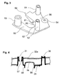
- Fig. 3 shows a schematically illustrated node element 50 with a first fork leg 55 and second fork leg 56 and a fork bridge 62nd Der first fork leg 55 contains a connection point for a body structure in Form of a sleeve-shaped Anformung 53.
- the second fork leg 56 includes a connection point for supporting or storing a motor module in the form a sleeve-shaped Anformung 51.
- Another motor module connection point in The shape of a sleeve-like molding 52 is in the connecting part, i. in the fork bridge 62, between the two fork legs 55, 56 arranged.
- the node element 50 contains a further connection point 54 in the form of a continuous Recess for connection of e.g. Connecting struts or more Aggregates.
- the two fork legs 55, 56 contain inner, facing each other and the fork gap limiting wall sections 60, which ever have a recess 61 as a connection interface for a link element.
- the cross-sectional view in Fig. 4 by the section line A - A according to FIG. 2 shows the node element 35 with the first sleeve-shaped Anformung 31 for connection of the subframe to the body structure and the second sleeve-shaped Anformung 36 for supporting a motor module on the subframe.
- the two sleeve-shaped Formations 31, 36 are on Gabeischenkeln the node element 35 arranged.
- the two sleeve-shaped projections 31, 36 are in recesses embedded in the side support 32a. They cross this completely and protrude with their end portions by a certain amount over its upper support surface out.
- the sleeve-shaped projection 36 of the engine module connection point has in its upper end portion on a pan-like depression, which by a chamber wall is formed in the Anformung.
- the sleeve-shaped Anformung 31 of the body-connection point has in her upper end portion of an annular, full-scale constriction 57 of the chamber on.
- the constriction 57 serves bsp. for receiving a nut in order Fixation of a bolt (not shown).
- the two fork legs contain inner, facing each other and the fork gap bounding wall sections 58 with connection points (not shown) for a handlebar element. Between the two fork legs is in too a U-shaped cross-section end portion of the transverse profile 34th carried out. The said end portion is in a in the lower support surface of the Side support 32a provided recessed recess.
Landscapes
- Engineering & Computer Science (AREA)
- Chemical & Material Sciences (AREA)
- Combustion & Propulsion (AREA)
- Transportation (AREA)
- Mechanical Engineering (AREA)
- Body Structure For Vehicles (AREA)
Abstract
Description
- Fig. 1:
- eine Unteransicht eines schematisch dargestellten Hilfsrahmens gemäss Erfindung;
- Fig. 2:
- eine perspektivische Draufsicht des Verbindungsabschnittes zwischen Seitenträger und Querträger gemäss Erfindung;
- Fig. 3:
- eine perspektivische Ansicht eines Knotenelementes;
- Fig. 4:
- einen Querschnitt durch die Schnittlinie A - A gemäss Fig. 2.
Claims (23)
- Hilfsrahmen (1) für Kraftfahrzeuge, insbesondere für Vorderachsen von Personenkraftwagen, enthaltend zwei in Abstand zueinander angeordnete, in Fahrzeuglängsrichtung ausgerichtete Seitenträger (2a, 2b) sowie wenigstens einen die beiden Seitenträger miteinander verbindenden Querträger (4), wobei der Querträger jeweils über ein versteifendes Knotenelement (5, 6) mit den Seitenträgern verbunden ist,
dadurch gekennzeichnet, dass
das Knotenelement (5, 6) wenigstens eine integrierte, wenigstens einer der Trägerflächen des Seitenträgers (2a, 2b) anliegende Seitenträger-Auflagefläche und wenigstens eine integrierte, wenigstens einer der Trägerflächen des Querträgers (4) anliegende Querträger-Auflagefläche sowie wenigstens eine integrierte Anschlussstelle für die Anbindung oder Abstützung einer Fahrzeugkomponente enthält, wobei die Anschlusstelle eine von der Seitenträger-Auflagefläche vorstehende und in einer Ausnehmung durch den Seitenträger (2a, 2b) oder eine von der Querträger-Auflagefläche vorstehende und in einer Ausnehmung durch den Querträger (4) geführte Anformung (9, 10, 12, 13) am Knotenelement (5, 6) ist. - Hilfsrahmen nach nach Anspruch 1, wobei der Seitenträger (2a, 2b) im Bereich der Anbindung des Querträgers (4) durchgängig ausgebildet ist.
- Hilfsrahmen einem der Ansprüche 1 bis 2, wobei das Knotenelement ein Gussteil oder ein Extrusionsteil.
- Hilfsrahmen nach einem der Ansprüche 1 bis 3, wobei das Knotenelement (5, 6) wenigstens eine integrierte, der unteren Trägerfläche des Seitenträgers (2a, 2b) anliegende Seitenträger-Auflagefläche und wenigstens eine integrierte, der unteren Trägerfläche des Querträgers (4) anliegende Querträger-Auflagefläche sowie wenigstens eine integrierte Anschlussstelle für die Anbindung oder Abstützung einer Fahrzeugkomponente enthält, und die Anschlusstelle eine von der Seitenträger-Auflagefläche vorstehende und von unten in einer Ausnehmung durch den Seitenträger (2a, 2b) oder eine von der Querträger-Auflagefläche vorstehende und von unten in einer Ausnehmung durch den Querträger (4) geführte Anformung (9,10,12,13) am Knotenelement (5, 6) ist.
- Hilfsrahmen nach einem der Ansprüche 1 bis 4, wobei die Anschlussstelle eine Karosserie-Anschlussstelle, insbesondere eine Fahrzeuglängsträger-Anschlussstelle, zur Anbindung des Hilfsrahmens (1) an die Karosseriestruktur, insbesondere an den Fahrzeuglängsträger, oder eine Motormodul-Anschlussstelle zur Abstützung eines Motormoduls auf den Seitenträger (2a, 2b) oder den Querträger (4) ist.
- Hilfsrahmen nach einem der Ansprüche 1 bis 5, wobei die Anformung (9, 10, 12, 13, 14, 19) den Seitenträger (2a, 2b) oder den Querträger (4) vollständig durchstösst und andernends mit ihrem Endabschnitt aus der gegenüberliegenden Trägerfläche des Seitenträger (2a, 2b) oder des Querträgers (4) austritt.
- Hilfsrahmen nach einem der Ansprüche 1 bis 6, wobei die Anformung (9, 10, 12, 13, 14, 19) an ihrem freien, aus dem Seitenträger (2a, 2b) oder Querträger (4) austretenden Ende mit dem Seitenträger (2a, 2b) oder Querträger (4) verschweisst ist.
- Hilfsrahmen nach einem der Ansprüche 1 bis 7, wobei die Seitenträger (2a, 2b) und/oder die Querträger (4) Ein- oder Mehrkammerhohlprofile sind.
- Hilfsrahmen nach einem der Ansprüche 1 bis 8, wobei das Knotenelement (5, 6) ein Metallgussteil, vorzugsweise ein Leichtmetallgussteil, insbesondere ein Gussteil aus Aluminium oder einer Aluminiumlegierung ist.
- Hilfsrahmen nach einem der Ansprüche 1 bis 9, wobei das Knotenelement (5, 6) als flächiges Formteil mit wenigstens einer von diesem abstehenden Anformung (9,10, 12, 13, 14, 19) ausgebildet ist.
- Hilfsrahmen nach einem der Ansprüche 1 bis 10, wobei das Knotenelement (5, 6) ein einstückig mittels Druckguss, Kokillenguss oder Sandguss hergestelltes Formteil ist.
- Hilfsrahmen nach einem der Ansprüche 1 bis 11, wobei das Knotenelement (5, 6) eine erste integrierte Fahrzeuglängsträger-Anschlussstelle und eine zweite integrierte Motormodul-Anschlussstelle enthält, und die Anschlusstellen von einer Seitenträger-Auflagefläche vorstehende und von unten in einer Ausnehmung durch den Seitenträger geführte Anformung am Knotenelement (5, 6) sind.
- Hilfsrahmen nach einem der Ansprüche 1 bis 12, wobei das Knotenelement (5, 6) eine integrierte Anschlussstelle zur Anbindung oder Abstützung einer Fahrzeugkomponente enthält, und die Anschlussstelle eine von einer Querträger-Auflagefläche vorstehende und von unten in einer Ausnehmung durch den Querträger geführte Anformung (14, 19) am Knotenelement (5, 6) ist.
- Hilfsrahmen nach Anspruch 13, wobei die Anschlussstelle eine Motormodul-Anschlussstelle für die Abstützung eines Motormoduls auf den Querträger (4) oder eine Fahrzeuglängsträger-Anschlussstelle zur Anbindung des Hilfsrahmens an den Fahrzeuglängsträger ist.
- Hilfsrahmen nach einem der Ansprüche 13 bis 14, wobei die Anformung (14, 19) den Querträger (4) vollständig durchstösst und andernends mit ihrem Endabschnitt aus der oberen Trägerfläche des Querträgers (4) austritt.
- Hilfsrahmen nach einem der Ansprüche 13 bis 15, wobei die Anformung (14, 19) an ihrem freien, aus dem Querträger austretenden Ende mit dem Querträger (4) verschweisst ist.
- Hilfsrahmen nach einem der Ansprüche 1 bis 16, wobei das Knotenelement (5, 6) eine oder mehrere integrierte Anschlussstellen (15, 16) zur Anbindung von Aggregaten und/oder Streben enthält.
- Hilfsrahmen nach einem der Ansprüche 1 bis 17, wobei das Knotenelement (5, 6) gabelförmig mit einem ersten und zweiten jeweils eine Seitenträger-Auflagefläche ausbildenden Gabelschenkel (7a, 7b; 8a, 8b) ist.
- Hilfsrahmen nach Anspruch 18, wobei in einem ersten Gabelschenkel (7a, 8a) eine Motormodul-Anschlussstelle und/oder in einem zweiten Gabelschenkel (7b, 8b) eine Fahrzeuglängsträger-Anschlussstelle ausgebildet ist.
- Hilfsrahmen nach einem der Ansprüche 18 bis 19, wobei der Endabschnitt des Querträgers (4) unter Anlage an der unteren Trägerfläche des Seitenträgers (2a, 2b) zwischen dem ersten und zweiten Gabelschenkel (7a, 7b; 8a, 8b) hindurchgeführt ist.
- Hilfsrahmen nach Anspruch 20, wobei der zwischen dem ersten und zweiten Gabelschenkel (7a, 7b; 8a, 8b) angeordnete Endabschnitt des Querträgers (4) als Anschlussstelle für Lenkerelemente in Form eines U-förmigen Querschnitt ausbildet ist.
- Hilfsrahmen nach einem der Ansprüche 1 bis 21, wobei im Knotenelement (5) eine Anschlussstelle für einen Fahrwerkslenker ausgeführt ist.
- Hilfsrahmen nach einem der Ansprüche 1 bis 22, wobei die Anformung hülsen- oder zapfenförmig ausgebildet ist.
Priority Applications (1)
| Application Number | Priority Date | Filing Date | Title |
|---|---|---|---|
| EP04015587A EP1591348A3 (de) | 2004-04-29 | 2004-07-02 | Anordnung zur Verbindung von RahmenlängsträgernHilfsrahmen für Kraftfahrzeuge |
Applications Claiming Priority (3)
| Application Number | Priority Date | Filing Date | Title |
|---|---|---|---|
| EP04405267A EP1591349A1 (de) | 2004-04-29 | 2004-04-29 | Anordnung zur Verbindung von Rahmenlängsträgern |
| EP04405267 | 2004-04-29 | ||
| EP04015587A EP1591348A3 (de) | 2004-04-29 | 2004-07-02 | Anordnung zur Verbindung von RahmenlängsträgernHilfsrahmen für Kraftfahrzeuge |
Publications (2)
| Publication Number | Publication Date |
|---|---|
| EP1591348A2 true EP1591348A2 (de) | 2005-11-02 |
| EP1591348A3 EP1591348A3 (de) | 2006-09-20 |
Family
ID=35445662
Family Applications (1)
| Application Number | Title | Priority Date | Filing Date |
|---|---|---|---|
| EP04015587A Withdrawn EP1591348A3 (de) | 2004-04-29 | 2004-07-02 | Anordnung zur Verbindung von RahmenlängsträgernHilfsrahmen für Kraftfahrzeuge |
Country Status (1)
| Country | Link |
|---|---|
| EP (1) | EP1591348A3 (de) |
Cited By (7)
| Publication number | Priority date | Publication date | Assignee | Title |
|---|---|---|---|---|
| DE102005045295A1 (de) * | 2005-09-22 | 2007-04-05 | Audi Ag | Fahrschemel für ein Kraftfahrzeug |
| DE102005045297A1 (de) * | 2005-09-22 | 2007-04-05 | Audi Ag | Trägerrahmen für ein Kraftfahrzeug |
| DE102006001709A1 (de) * | 2006-01-13 | 2007-07-26 | Audi Ag | Hilfsrahmen für ein Kraftfahrzeug, insbesondere für einen Personenkraftwagen |
| CN102717833A (zh) * | 2012-06-20 | 2012-10-10 | 上汽通用五菱汽车股份有限公司 | 汽车的安装支撑机构 |
| CN103342135A (zh) * | 2013-07-26 | 2013-10-09 | 乐至县熊猫机器制造有限公司 | 一种扫路车副车架的高精度安装方法 |
| DE102013016758A1 (de) * | 2013-10-10 | 2015-04-16 | Audi Ag | Hilfsrahmen für ein Kraftfahrzeug |
| DE102012005561B4 (de) | 2012-01-28 | 2025-01-02 | Volkswagen Aktiengesellschaft | Hilfsrahmen für ein Kraftfahrzeug |
Family Cites Families (6)
| Publication number | Priority date | Publication date | Assignee | Title |
|---|---|---|---|---|
| US1473651A (en) * | 1921-09-12 | 1923-11-13 | Smith Corp A O | Automobile frame and pressed-steel constructional elements therefor |
| US1872386A (en) * | 1930-05-02 | 1932-08-16 | Smith Corp A O | Automobile frame |
| JP2630578B2 (ja) * | 1995-06-08 | 1997-07-16 | 株式会社ワン・エイティ | 覆工版の連結構造 |
| US5634663A (en) * | 1995-10-18 | 1997-06-03 | Dana Corporation | Vehicle frame joint |
| FI112191B (fi) * | 2000-12-12 | 2003-11-14 | Tauno Kulojaervi | Ajoneuvon runko ja kiinnityskappale runkopalkkien yhteenliittämistä varten |
| US6561574B1 (en) * | 2002-03-06 | 2003-05-13 | Dwws, Llc | Cross member support |
-
2004
- 2004-07-02 EP EP04015587A patent/EP1591348A3/de not_active Withdrawn
Cited By (11)
| Publication number | Priority date | Publication date | Assignee | Title |
|---|---|---|---|---|
| DE102005045295A1 (de) * | 2005-09-22 | 2007-04-05 | Audi Ag | Fahrschemel für ein Kraftfahrzeug |
| DE102005045297A1 (de) * | 2005-09-22 | 2007-04-05 | Audi Ag | Trägerrahmen für ein Kraftfahrzeug |
| DE102005045295B4 (de) * | 2005-09-22 | 2010-04-15 | Audi Ag | Fahrschemel für ein Kraftfahrzeug |
| DE102005045297B4 (de) * | 2005-09-22 | 2012-05-24 | Audi Ag | Trägerrahmen für ein Kraftfahrzeug |
| DE102006001709A1 (de) * | 2006-01-13 | 2007-07-26 | Audi Ag | Hilfsrahmen für ein Kraftfahrzeug, insbesondere für einen Personenkraftwagen |
| DE102012005561B4 (de) | 2012-01-28 | 2025-01-02 | Volkswagen Aktiengesellschaft | Hilfsrahmen für ein Kraftfahrzeug |
| CN102717833A (zh) * | 2012-06-20 | 2012-10-10 | 上汽通用五菱汽车股份有限公司 | 汽车的安装支撑机构 |
| CN102717833B (zh) * | 2012-06-20 | 2016-06-29 | 上汽通用五菱汽车股份有限公司 | 汽车的安装支撑机构 |
| CN103342135A (zh) * | 2013-07-26 | 2013-10-09 | 乐至县熊猫机器制造有限公司 | 一种扫路车副车架的高精度安装方法 |
| DE102013016758A1 (de) * | 2013-10-10 | 2015-04-16 | Audi Ag | Hilfsrahmen für ein Kraftfahrzeug |
| US9434416B2 (en) | 2013-10-10 | 2016-09-06 | Audi Ag | Subframe for a motor vehicle |
Also Published As
| Publication number | Publication date |
|---|---|
| EP1591348A3 (de) | 2006-09-20 |
Similar Documents
| Publication | Publication Date | Title |
|---|---|---|
| EP1690779B1 (de) | Hilfsrahmen für Kraftfahrzeuge | |
| EP1386829B1 (de) | Aufbaustruktur eines Personenkraftwagens | |
| DE102008010553B4 (de) | Hilfsrahmen für eine Vorderachse eines Kraftfahrzeugs | |
| DE602004013196T2 (de) | Fahrgestell-Modul für Kraftfahrzeuge | |
| EP1829767B1 (de) | Hilfsrahmen zur Befestigung an einer Karosserie eines Kraftwagens | |
| EP2057041B1 (de) | Energieabsorptionsvorrichtung, insbesondere für nichtaxiale belastung | |
| DE102004028161B4 (de) | Unterfahrschutz für Personenkraftfahrzeuge zur Anordnung unter Längsträgerniveau vor einem Hilfsrahmen oder Achsträger als zusätzliche Crashebene | |
| EP0836983B1 (de) | Vorderwandrahmen für eine selbsttragende Karosserie eines Personenkraftwagens und Verfahren zu seiner Herstellung | |
| DE19730404A1 (de) | Hilfsrahmen für Kraftfahrzeuge | |
| DE202014102248U1 (de) | Verbindung eines Rahmenlängsträgers und einer Säule eines Fahrszeugs | |
| DE102009004310B4 (de) | Fahrschemel, insbesondere Vorderachsträger | |
| DE102011053246A1 (de) | Karosserie und Fahrzeug | |
| EP1138581A2 (de) | Karosseriebauteil aus Stahl | |
| EP1840006B1 (de) | Fahrzeugkarosserie mit Querträgerstruktur für einen Sitzbereich des Fahrzeugs | |
| DE19746238B4 (de) | Karosserieaufbau eines Personenkraftwagens | |
| DE102004012500B4 (de) | Aufbaustruktur für eine Karosserie von Kraftfahrzeugen | |
| DE102006041092B4 (de) | Knautschzone einer Karosserie eines Kraftwagens | |
| DE102010049427B4 (de) | Querträgeranordnung, insbesondere Fersenblechanordnung in einer Fahrzeugkarosserie | |
| DE102004019750A1 (de) | Heckseitige Tragstruktur für ein Personenkraftfahrzeug | |
| EP1591349A1 (de) | Anordnung zur Verbindung von Rahmenlängsträgern | |
| DE102006009290B4 (de) | Tragstruktur für ein Frontend eines Kraftwagens | |
| EP1591348A2 (de) | Anordnung zur Verbindung von RahmenlängsträgernHilfsrahmen für Kraftfahrzeuge | |
| WO2020094742A1 (de) | Vorbaustrukturanordnung für einen kraftwagenrohbau sowie aggregateträger für eine derartige vorbaustrukturanordnung | |
| WO2012113433A1 (de) | Hilfsrahmen aus extrudierten profile mit deckel für eine karosserie eines kraftwagens | |
| DE10032663B4 (de) | Kraftwagen mit einer selbsttragenden Karosserie |
Legal Events
| Date | Code | Title | Description |
|---|---|---|---|
| PUAI | Public reference made under article 153(3) epc to a published international application that has entered the european phase |
Free format text: ORIGINAL CODE: 0009012 |
|
| AK | Designated contracting states |
Kind code of ref document: A2 Designated state(s): AT BE BG CH CY CZ DE DK EE ES FI FR GB GR HU IE IT LI LU MC NL PL PT RO SE SI SK TR |
|
| AX | Request for extension of the european patent |
Extension state: AL HR LT LV MK |
|
| PUAL | Search report despatched |
Free format text: ORIGINAL CODE: 0009013 |
|
| AK | Designated contracting states |
Kind code of ref document: A3 Designated state(s): AT BE BG CH CY CZ DE DK EE ES FI FR GB GR HU IE IT LI LU MC NL PL PT RO SE SI SK TR |
|
| AX | Request for extension of the european patent |
Extension state: AL HR LT LV MK |
|
| AKX | Designation fees paid | ||
| STAA | Information on the status of an ep patent application or granted ep patent |
Free format text: STATUS: THE APPLICATION IS DEEMED TO BE WITHDRAWN |
|
| 18D | Application deemed to be withdrawn |
Effective date: 20070201 |
|
| REG | Reference to a national code |
Ref country code: DE Ref legal event code: 8566 |