EP1591345B1 - Electric power-steering device - Google Patents
Electric power-steering device Download PDFInfo
- Publication number
- EP1591345B1 EP1591345B1 EP04707630A EP04707630A EP1591345B1 EP 1591345 B1 EP1591345 B1 EP 1591345B1 EP 04707630 A EP04707630 A EP 04707630A EP 04707630 A EP04707630 A EP 04707630A EP 1591345 B1 EP1591345 B1 EP 1591345B1
- Authority
- EP
- European Patent Office
- Prior art keywords
- driving pulley
- gear
- end portion
- housing
- shaft
- Prior art date
- Legal status (The legal status is an assumption and is not a legal conclusion. Google has not performed a legal analysis and makes no representation as to the accuracy of the status listed.)
- Expired - Lifetime
Links
- 230000007246 mechanism Effects 0.000 claims abstract description 31
- 230000009467 reduction Effects 0.000 claims abstract description 31
- 238000006243 chemical reaction Methods 0.000 claims description 5
- 238000010586 diagram Methods 0.000 description 4
- 230000005540 biological transmission Effects 0.000 description 3
- 230000004075 alteration Effects 0.000 description 1
- 230000003247 decreasing effect Effects 0.000 description 1
- 238000006073 displacement reaction Methods 0.000 description 1
- 230000000694 effects Effects 0.000 description 1
- 230000000149 penetrating effect Effects 0.000 description 1
- 125000006850 spacer group Chemical group 0.000 description 1
Images


Classifications
-
- F—MECHANICAL ENGINEERING; LIGHTING; HEATING; WEAPONS; BLASTING
- F16—ENGINEERING ELEMENTS AND UNITS; GENERAL MEASURES FOR PRODUCING AND MAINTAINING EFFECTIVE FUNCTIONING OF MACHINES OR INSTALLATIONS; THERMAL INSULATION IN GENERAL
- F16H—GEARING
- F16H37/00—Combinations of mechanical gearings, not provided for in groups F16H1/00 - F16H35/00
- F16H37/02—Combinations of mechanical gearings, not provided for in groups F16H1/00 - F16H35/00 comprising essentially only toothed or friction gearings
-
- B—PERFORMING OPERATIONS; TRANSPORTING
- B62—LAND VEHICLES FOR TRAVELLING OTHERWISE THAN ON RAILS
- B62D—MOTOR VEHICLES; TRAILERS
- B62D5/00—Power-assisted or power-driven steering
- B62D5/04—Power-assisted or power-driven steering electrical, e.g. using an electric servo-motor connected to, or forming part of, the steering gear
- B62D5/0421—Electric motor acting on or near steering gear
- B62D5/0424—Electric motor acting on or near steering gear the axes of motor and final driven element of steering gear, e.g. rack, being parallel
-
- F—MECHANICAL ENGINEERING; LIGHTING; HEATING; WEAPONS; BLASTING
- F16—ENGINEERING ELEMENTS AND UNITS; GENERAL MEASURES FOR PRODUCING AND MAINTAINING EFFECTIVE FUNCTIONING OF MACHINES OR INSTALLATIONS; THERMAL INSULATION IN GENERAL
- F16H—GEARING
- F16H25/00—Gearings comprising primarily only cams, cam-followers and screw-and-nut mechanisms
- F16H25/18—Gearings comprising primarily only cams, cam-followers and screw-and-nut mechanisms for conveying or interconverting oscillating or reciprocating motions
- F16H25/20—Screw mechanisms
- F16H2025/2062—Arrangements for driving the actuator
- F16H2025/2096—Arrangements for driving the actuator using endless flexible members
-
- F—MECHANICAL ENGINEERING; LIGHTING; HEATING; WEAPONS; BLASTING
- F16—ENGINEERING ELEMENTS AND UNITS; GENERAL MEASURES FOR PRODUCING AND MAINTAINING EFFECTIVE FUNCTIONING OF MACHINES OR INSTALLATIONS; THERMAL INSULATION IN GENERAL
- F16H—GEARING
- F16H7/00—Gearings for conveying rotary motion by endless flexible members
- F16H7/02—Gearings for conveying rotary motion by endless flexible members with belts; with V-belts
- F16H7/023—Gearings for conveying rotary motion by endless flexible members with belts; with V-belts with belts having a toothed contact surface or regularly spaced bosses or hollows for slipless or nearly slipless meshing with complementary profiled contact surface of a pulley
Definitions
- the present invention relates to an electric power steering apparatus in which steering assist force is generated by an electric motor.
- a reduction gear mechanism comprising a pulley-belt mechanism and thereafter converted into the axial movement of a rack shaft, for example, through a ball screw mechanism surrounding the rack shaft (see, for example, Japanese Examined Patent Publication No. 4(1992)-28583 ).
- the abovementioned pulley-belt mechanism comprises a small pulley disposed on the same axis line with an output shaft of the electric motor, and a large pulley surrounding the rack shaft.
- a reduction gear mechanism of such a kind of electric power steering apparatus is required to be small-sized and at the same time to obtain a high reduction gear ratio.
- Document EP 1 270 369 A2 discloses a ball-screw assembly isolator which is driven by an electric motor.
- a driving pulley is attached to an end of a motor shaft.
- a bearing supports the shaft rotabably.
- a belt is wrapped around the driving pulley and around the isolator.
- the isolator includes a ball-screw nut container having a first shell and a second shell. The first shell and the second shell have a cylindrical shape. The first shell functions as a driven pulley.
- Document DE 115 719 B discloses a device for adjusting the tension and increasing the friction of belt drives, wherein an inscribed gear having external teeth meshes with a circumscribed gear having internal teeth.
- the rotation speed of the output shaft of the electric motor is reduced by the inscribed gear and the circumscribed gear, and thereafter it is reduced by the ratio between the diameters of the driving pulley and the driven pulley. Since the speed reduction using the inscribed gear and the circumscribed gear can heighten the reduction gear ratio, a high reduction gear ratio can be achieved with a small-sized reduction gear mechanism as a whole without a small-diameter driving pulley or a large-diameter driven pulley, thus to obtain a good mountability on a vehicle. Further, since it is not necessary to reduce the radius of curvature of the region of the driving pulley on which the belt is wound, the life of the belt can be extended.
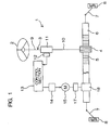
- Fig. 1 is a pattern diagram of the schematic structure of an electric power steering apparatus according to an embodiment of the present invention.
- the electric power steering apparatus (EPS) 1 comprises a steering shaft 3 connected to a steering wheel 2 as a steering member at an end of the steering shaft 3, a pinion 4 provided at the other end of the steering shaft 3, and a rack shaft 6 as a steerable shaft having rack teeth 5 engageable with the pinion 4 and extending in the direction of the width (transverse direction) of a vehicle.
- this rotation of the steering shaft 3 is converted through the pinion 4 and the rack teeth 5 into linear movement of the rack shaft 6 in the lateral direction of the vehicle. Thereby, the rotational steering of the wheels can be achieved.
- the steering shaft 3 is divided into an input shaft 9 connected to the steering wheel 2 and an output shaft 10 connected to the pinion 4.
- the input shaft 9 and the output shaft 10 are connected to each other through a torsion bar 11 on the same axial line.
- a torque sensor 12 is provided for detecting the steering torque on the basis of the relative rotational displacement amount between the input and output shafts 9, 10 connected through the torsion bar 11.
- the steering torque data detected by the torque sensor 12 are given to a control section 13.
- electric current to be applied to a steering assist electric motor 15 is controlled through a driver 14 on the basis of the detected torque data, detected vehicle speed data or the like.
- the rotation speed of an output shaft 16 (see Fig. 2 ) of the electric motor 15 is reduced by a reduction gear mechanism 17 comprising a pulley-belt mechanism.
- the output rotation of the reduction gear mechanism 17 is converted through a conversion mechanism 18 into the axial movement of the rack shaft 6 thereby to assist the steering.
- the electric power steering apparatus 1 is a so-called rack assist type one.
- Fig .2 is an enlarged sectional view of the main part of the electric power steering apparatus 1 and Fig. 3 is an enlarged sectional view of the main part of Fig. 2 .
- a rack housing 19 comprises a cylindrical main housing 20 and an end portion housing 21 connected to each other.
- a reduction gear housing 22 is integrally provided at the connecting portion between the main housing 20 and the end portion housing 21.
- the end portion housing 21 comprises a small-diameter part 24 holding a rack bush 23 slidably supporting the rack shaft 6, and a large-diameter part 25 forming the reduction gear housing 22.
- a flange 26 provided at the end of the large-diameter part 25 and a side plate 27 standing from the main housing 20 abut each other and are connected to each other by a connection screw 28.
- the electric motor 15 is juxtaposed with the rack housing 19 so that the output shaft 16 of the electric motor 15 is in parallel with the rack shaft 6.
- a cylindrical connection housing 30 is integrally provided with a motor housing 29 of the electric motor 15.
- An attachment flange 31 of the connection housing 30 and the side plate 27 of the main housing 20 abut each other and are connected to each other by a connection screw 32.
- connection housing 30 comprises a taper part 33 connected to the motor housing 29, a cylindrical part 35 inserted through a connection opening 34 of the side plate 27 into the reduction gear housing 22, and an annular step part 36 disposed between the taper part 33 and the cylindrical part 35.
- the reduction gear mechanism 17 comprises an input shaft 38 connected to the output shaft 16 of the electric motor 15 in the same axial line, for example, through a joint 37 using serration, an inscribed gear 39 formed on the circumferential surface of the input shaft 38, a circumscribed gear 40 in which the inscribed gear is inscribed, a driving pulley 41 provided on the outer circumference of the circumscribed gear 40, a driven pulley 42 (see Fig. 2 ) disposed so as to surround the rack shaft 6, and a belt 43 as an endless belt wound between the driving pulley 41 and the driven pulley 42.
- the distance between the central axis line 39a of the inscribed gear 39 (namely, the central axis line 38a of the input shaft 38) and the central axis line 42a of the driven pulley 42, namely, the center to center distance D2 between the inscribed gear 39 and the driven pulley 42, is longer than the distance between the central axis line 41a of the driving pulley 41 and the central axis line 42a of the driven pulley 42, namely, the center to center distance D1 between the driving pulley 41 and the driven pulley 42.
- the belt 43 comprises a toothed belt (cogged belt)
- the driving pulley 41 comprises a toothed pulley on the outer circumference of which teeth 44 are provided with equal spaces therebetween on the circumference so as to be engageable with the toothed belt.
- the driven pulley 42 comprises a toothed pulley.
- the input shaft 38 includes a first end portion 45, a second end portion 46 and an intermediate portion 80 between the first and second end portions 45, 46.
- the first end portion 45 of the input shaft 38 has, for example, serration, is inserted into the joint 37, and connected through the joint 37 to the output shaft 16 of the electric motor 15 so as to be rotatable integrally with the output shaft 16.
- a portion 81 close to the first end portion 45 is rotatably supported by a first bearing 47 held by a first support hole 48 of the cylindrical part 35 of the connection housing 30.
- An inner ring 49 of the first bearing 47 is held between a positioning step part 50 of the input shaft 38 and a check nut 52 screwed into a screw part 51 so that the axial movement of the inner ring 49 with respect to the input shaft 38 is restricted.
- An outer ring 53 of the first bearing 47 is held between a positioning step part 54 of the first support hole 48 and a cylindrical setscrew 56 screwed into a screw part 55 of the first support hole 48 so that the axial movement of the outer ring 53 is restricted.
- the inscribed gear 39 is integrally formed from the second end portion 46 to the midway portion of the intermediate portion 80 thus to be engaged with the circumscribed gear 40 formed on the inner circumference of the cylindrical driving pulley 41.
- the driving pulley 41 has a shape of a bottomed cylinder and comprises a first end portion 91 and a second end portion 92.
- the first end portion 91 of the driving pulley 41 is opened and the second end portion 92 is closed by an end face plate 57.
- a support shaft 58 is formed so as to extend along the central axis line 41a of the driving pulley 41 from the end face plate 57 of the driving pulley 41.
- a second bearing 59 is held by a second support hole 60 in the cylindrical part 35 of the connection housing 30.
- the second bearing 59 is a support means for supporting the driving pulley 41 rotatably about the central axis line 41a through the support shaft 58. Further, since the driving pulley 41 is supported also by the abovementioned input shaft 38, it is supported at both ends and its operation is stable.
- the support shaft 58 is fitted into an inner ring 85 of the second bearing 59 so as to be integrally rotatable with the inner ring 85 of the second bearing 59. Further, the end face plate 57 of the driving pulley 41 is in contact with the end face of the inner ring 85, the axial movement of the driving pulley 41 is restricted. An outer ring 86 of the second bearing 59 is press fitted into the abovementiond second support hole 60.
- the cylindrical part 35 of the connection housing 30 contains the inscribed gear 39, the subscribed gear 40 and the driving pulley 41. Further, the cylindrical part 35 has an opening 94 for passing the belt 43 therethrough. The first end portion 91 of the driving pulley 41 is opposed to the edge of the opening 94 with a small distance therebetween, so that excessive inclination of the driving pulley 41 is restricted.
- the conversion mechanism 18 for example, a ball screw mechanism or a bearing screw mechanism (see, e.g. Japanese Unexamined Patent Publication No. 2000-46136 ) is used for converting the rotational movement into the linear movement.
- a ball screw mechanism for example, a ball screw mechanism or a bearing screw mechanism (see, e.g. Japanese Unexamined Patent Publication No. 2000-46136 ) is used for converting the rotational movement into the linear movement.
- a ball screw mechanism is described.
- the conversion mechanism 18 includes a ball nut 61 as a rotational member surrounding the circumference of the rack shaft 6.
- the ball nut 61 is threadedly engaged with a ball screw thread 62 formed in the midway portion of the rack shaft 6 through balls 63 thus to constitute the conversion mechanism 18.
- the ball nut 62 is rotatably supported by the rack housing 19 through a third bearing 64 and a fourth bearing 65.
- the abovementioned driven pulley 42 is put on the outer circumferential part 66 of the ball nut 61 so as to integrally rotate with the outer circumferential part 66 of the ball nut 61.
- an inner ring 70 of a fourth bearing 65, an annular spacer 71 and the driven pulley 42 are integrally held between a positioning step part 67 formed on the outer circumferential part 66 of the ball nut 61 and a check nut 69 threaded into a screw portion 68 of the outer circumferential part 66, the driven pulley 42 is attached to the ball nut 61 so as to integrally rotate therewith.
- the inner ring 70 of the fourth bearing 65 and the driven pulley 42 are restricted from moving in the axial direction with respect to the ball nut 61.
- the fourth bearing 65 comprises, for example, a doublerow angular contact ball bearing.
- the rotation speed of the output shaft 16 of the electric motor 15 is reduced by the inscribed gear 39 and the circumscribed gear 40, and thereafter further reduced by the ratio between the diameters of the driving pulley 41 and the driven pulley 42. Since the speed reduction using the inscribed gear 39 and the circumscribed gear 40 can heighten the reduction gear ratio, a high reduction gear ratio can be achieved with the small-sized reduction gear mechanism 17 as a whole without decreasing the diameter of the driving pulley 41 or increasing the diameter of the driven pulley 42, thus to obtain a good mountability on a vehicle. Further, since it is not necessary to reduce the radius of curvature of the region of the driving pulley 41 on which the belt 43 is wound, the life of the belt 43 can be extended.
- the reduction gear housing 22 supports the driving pulley 41 through the second bearing 59 so as to rotate about its central axis line 41a, the driving pulley 41 can be stably supported.
- Fig. 5 illustrates another embodiment of the present invention.
- this embodiment differs from the embodiment of Fig. 3 mainly in the following point. That is, in the embodiment of Fig. 3 , the driving pulley 41 is supported rotatably about its central axis line 41a, while in this embodiment, the driving pulley 41 0 is swingably supported by the inscribed gear 39 of an input shaft 380.
- similar parts to those of Fig. 3 are designated with the same reference characters and description thereof will be omitted.
- the driving pulley 410 has a through hole 93 opened at a first end portion 91 and a second end portion 92.
- the input shaft 380 comprising a penetrating shaft penetrates through the through hole 93 of the driving pulley 410.
- the second end portion 46 of the input shaft 380 is rotatably supported through the second bearing 59 by the second support hole 60 in the cylindrical part 35 of the connection housing 30.
- the cylindrical part 35 of the connection housing 30 has an opening 94 for passing the belt 43 therethrough.
- a pair of guide parts 76, 77 are formed so as to be opposed to the first and second end portions 91, 92, the driving pulley 410, respectively.
- a flat belt or a chain belt can be used instead of a toothed belt.
- an inscribed gear formed separately from the input shaft may be attached to the outer circumference of the input shaft.
- a circumscribed gear formed separately from the driving pulley may be attached to the inner circumference of the driving pulley.
Landscapes
- Engineering & Computer Science (AREA)
- General Engineering & Computer Science (AREA)
- Mechanical Engineering (AREA)
- Chemical & Material Sciences (AREA)
- Combustion & Propulsion (AREA)
- Transportation (AREA)
- Power Steering Mechanism (AREA)
- Transmission Devices (AREA)
Abstract
Description
- The present invention relates to an electric power steering apparatus in which steering assist force is generated by an electric motor.
- In a rack assist type electric power steering apparatus, the rotation of an electric motor is slowed down by a reduction gear mechanism comprising a pulley-belt mechanism and thereafter converted into the axial movement of a rack shaft, for example, through a ball screw mechanism surrounding the rack shaft (see, for example, Japanese Examined Patent Publication No.
4(1992)-28583 - The abovementioned pulley-belt mechanism comprises a small pulley disposed on the same axis line with an output shaft of the electric motor, and a large pulley surrounding the rack shaft.
- A reduction gear mechanism of such a kind of electric power steering apparatus is required to be small-sized and at the same time to obtain a high reduction gear ratio.
- However, if the small pulley is made small-diameter for this purpose, the radius of curvature of a belt region wound on the small pulley becomes small and it is feared that the life of belt is shortened because of its flexion fatigue. Besides, it is feared that torque transmission loss is caused by increased inner friction at curved portions of the belt.
- On the contrary, if the large pulley is made large-diameter, the whole apparatus becomes large thus to lessen its mountability on a vehicle.
-
Document EP 1 270 369 A2 discloses a ball-screw assembly isolator which is driven by an electric motor. A driving pulley is attached to an end of a motor shaft. A bearing supports the shaft rotabably. A belt is wrapped around the driving pulley and around the isolator. The isolator includes a ball-screw nut container having a first shell and a second shell. The first shell and the second shell have a cylindrical shape. The first shell functions as a driven pulley. - Document
DE 115 719 B discloses a device for adjusting the tension and increasing the friction of belt drives, wherein an inscribed gear having external teeth meshes with a circumscribed gear having internal teeth. - It is an object of the invention to provide an improved electric power steering apparatus.
- Preferably, it is an object of the present invention to provide an electric power steering apparatus which is small-sized and suitably mountable on a vehicle, and can achieve a high reduction gear ratio and high durability.
- According to the invention, the above object is achieved by an electric power steering apparatus of
claim 1. - According to this embodiment, the rotation speed of the output shaft of the electric motor is reduced by the inscribed gear and the circumscribed gear, and thereafter it is reduced by the ratio between the diameters of the driving pulley and the driven pulley. Since the speed reduction using the inscribed gear and the circumscribed gear can heighten the reduction gear ratio, a high reduction gear ratio can be achieved with a small-sized reduction gear mechanism as a whole without a small-diameter driving pulley or a large-diameter driven pulley, thus to obtain a good mountability on a vehicle. Further, since it is not necessary to reduce the radius of curvature of the region of the driving pulley on which the belt is wound, the life of the belt can be extended.
-
-
Fig. 1 is a pattern diagram of the schematic structure of an electric power steering apparatus according to an embodiment of the present invention. -
Fig .2 is sectional view of the main part of an electric power steering apparatus. -
Fig. 3 is an enlarged sectional view of the main part ofFig. 2 . -
Fig. 4 is a pattern diagram of a reduction gear mechanism. -
Fig. 5 is an enlarged sectional view of the main part of an electric power steering apparatus according to another embodiment of the present invention. -
Figs. 6A and 6B are pattern diagrams of a reduction gear mechanism, in which the load increases fromFig. 6A to Fig. 6B . - Preferred embodiments of the present invention will be described below with reference to the appended drawings.
-
Fig. 1 is a pattern diagram of the schematic structure of an electric power steering apparatus according to an embodiment of the present invention. Referring toFig. 1 , the electric power steering apparatus (EPS) 1 comprises asteering shaft 3 connected to asteering wheel 2 as a steering member at an end of thesteering shaft 3, apinion 4 provided at the other end of thesteering shaft 3, and arack shaft 6 as a steerable shaft havingrack teeth 5 engageable with thepinion 4 and extending in the direction of the width (transverse direction) of a vehicle. - Connected respectively to both ends of the
rack shaft 6 aretie rods 7, each of which is connected through a corresponding knuckle arm (not shown) to acorresponding wheel 8. When thesteering wheel 2 is operated to rotate thesteering shaft 3, this rotation of thesteering shaft 3 is converted through thepinion 4 and therack teeth 5 into linear movement of therack shaft 6 in the lateral direction of the vehicle. Thereby, the rotational steering of the wheels can be achieved. - The
steering shaft 3 is divided into aninput shaft 9 connected to thesteering wheel 2 and anoutput shaft 10 connected to thepinion 4. Theinput shaft 9 and theoutput shaft 10 are connected to each other through atorsion bar 11 on the same axial line. - A
torque sensor 12 is provided for detecting the steering torque on the basis of the relative rotational displacement amount between the input andoutput shafts torsion bar 11. The steering torque data detected by thetorque sensor 12 are given to acontrol section 13. In thecontrol section 13, electric current to be applied to a steering assistelectric motor 15 is controlled through adriver 14 on the basis of the detected torque data, detected vehicle speed data or the like. The rotation speed of an output shaft 16 (seeFig. 2 ) of theelectric motor 15 is reduced by areduction gear mechanism 17 comprising a pulley-belt mechanism. The output rotation of thereduction gear mechanism 17 is converted through aconversion mechanism 18 into the axial movement of therack shaft 6 thereby to assist the steering. The electricpower steering apparatus 1 is a so-called rack assist type one. -
Fig .2 is an enlarged sectional view of the main part of the electricpower steering apparatus 1 andFig. 3 is an enlarged sectional view of the main part ofFig. 2 . - Referring to
Figs. 2 and3 , arack housing 19 comprises a cylindricalmain housing 20 and anend portion housing 21 connected to each other. Areduction gear housing 22 is integrally provided at the connecting portion between themain housing 20 and the end portion housing 21. - In concrete terms, the
end portion housing 21 comprises a small-diameter part 24 holding arack bush 23 slidably supporting therack shaft 6, and a large-diameter part 25 forming thereduction gear housing 22. Aflange 26 provided at the end of the large-diameter part 25 and aside plate 27 standing from themain housing 20 abut each other and are connected to each other by aconnection screw 28. - The
electric motor 15 is juxtaposed with therack housing 19 so that theoutput shaft 16 of theelectric motor 15 is in parallel with therack shaft 6. Acylindrical connection housing 30 is integrally provided with amotor housing 29 of theelectric motor 15. Anattachment flange 31 of the connection housing 30 and theside plate 27 of themain housing 20 abut each other and are connected to each other by aconnection screw 32. - The
connection housing 30 comprises ataper part 33 connected to themotor housing 29, acylindrical part 35 inserted through a connection opening 34 of theside plate 27 into thereduction gear housing 22, and anannular step part 36 disposed between thetaper part 33 and thecylindrical part 35. By abutting theannular step part 36 against theside plate 27, themotor housing 29 is positioned in the axial direction with respect to thereduction gear housing 22 through theconnection housing 30. - Referring mainly to
Fig. 3 , thereduction gear mechanism 17 comprises aninput shaft 38 connected to theoutput shaft 16 of theelectric motor 15 in the same axial line, for example, through ajoint 37 using serration, an inscribedgear 39 formed on the circumferential surface of theinput shaft 38, acircumscribed gear 40 in which the inscribed gear is inscribed, adriving pulley 41 provided on the outer circumference of thecircumscribed gear 40, a driven pulley 42 (seeFig. 2 ) disposed so as to surround therack shaft 6, and abelt 43 as an endless belt wound between thedriving pulley 41 and the drivenpulley 42. - The distance between the
central axis line 39a of the inscribed gear 39 (namely, thecentral axis line 38a of the input shaft 38) and thecentral axis line 42a of the drivenpulley 42, namely, the center to center distance D2 between the inscribedgear 39 and the drivenpulley 42, is longer than the distance between thecentral axis line 41a of thedriving pulley 41 and thecentral axis line 42a of the drivenpulley 42, namely, the center to center distance D1 between thedriving pulley 41 and the drivenpulley 42. - As shown in
Fig. 4 , for example, thebelt 43 comprises a toothed belt (cogged belt), and thedriving pulley 41 comprises a toothed pulley on the outer circumference of whichteeth 44 are provided with equal spaces therebetween on the circumference so as to be engageable with the toothed belt. Similarly, the drivenpulley 42 comprises a toothed pulley. - Referring to
Fig. 3 again, theinput shaft 38 includes afirst end portion 45, asecond end portion 46 and anintermediate portion 80 between the first andsecond end portions first end portion 45 of theinput shaft 38 has, for example, serration, is inserted into thejoint 37, and connected through thejoint 37 to theoutput shaft 16 of theelectric motor 15 so as to be rotatable integrally with theoutput shaft 16. Further, in theintermediate portion 80 of theinput shaft 38, aportion 81 close to thefirst end portion 45 is rotatably supported by a first bearing 47 held by afirst support hole 48 of thecylindrical part 35 of theconnection housing 30. - An
inner ring 49 of thefirst bearing 47 is held between apositioning step part 50 of theinput shaft 38 and acheck nut 52 screwed into ascrew part 51 so that the axial movement of theinner ring 49 with respect to theinput shaft 38 is restricted. Anouter ring 53 of thefirst bearing 47 is held between apositioning step part 54 of thefirst support hole 48 and acylindrical setscrew 56 screwed into ascrew part 55 of thefirst support hole 48 so that the axial movement of theouter ring 53 is restricted. - On the outer circumference of the
input shaft 38, the inscribedgear 39 is integrally formed from thesecond end portion 46 to the midway portion of theintermediate portion 80 thus to be engaged with the circumscribedgear 40 formed on the inner circumference of the cylindrical drivingpulley 41. - The driving
pulley 41 has a shape of a bottomed cylinder and comprises afirst end portion 91 and asecond end portion 92. Thefirst end portion 91 of the drivingpulley 41 is opened and thesecond end portion 92 is closed by anend face plate 57. Asupport shaft 58 is formed so as to extend along thecentral axis line 41a of the drivingpulley 41 from theend face plate 57 of the drivingpulley 41. Asecond bearing 59 is held by asecond support hole 60 in thecylindrical part 35 of theconnection housing 30. Thesecond bearing 59 is a support means for supporting the drivingpulley 41 rotatably about thecentral axis line 41a through thesupport shaft 58. Further, since the drivingpulley 41 is supported also by theabovementioned input shaft 38, it is supported at both ends and its operation is stable. - The
support shaft 58 is fitted into aninner ring 85 of thesecond bearing 59 so as to be integrally rotatable with theinner ring 85 of thesecond bearing 59. Further, theend face plate 57 of the drivingpulley 41 is in contact with the end face of theinner ring 85, the axial movement of the drivingpulley 41 is restricted. Anouter ring 86 of thesecond bearing 59 is press fitted into the abovementiondsecond support hole 60. - The
cylindrical part 35 of theconnection housing 30 contains the inscribedgear 39, the subscribedgear 40 and the drivingpulley 41. Further, thecylindrical part 35 has anopening 94 for passing thebelt 43 therethrough. Thefirst end portion 91 of the drivingpulley 41 is opposed to the edge of theopening 94 with a small distance therebetween, so that excessive inclination of the drivingpulley 41 is restricted. - Referring to
Fig. 2 again, as theconversion mechanism 18, for example, a ball screw mechanism or a bearing screw mechanism (see, e.g. Japanese Unexamined Patent Publication No.2000-46136 conversion mechanism 18 includes aball nut 61 as a rotational member surrounding the circumference of therack shaft 6. - The
ball nut 61 is threadedly engaged with aball screw thread 62 formed in the midway portion of therack shaft 6 throughballs 63 thus to constitute theconversion mechanism 18. Theball nut 62 is rotatably supported by therack housing 19 through athird bearing 64 and afourth bearing 65. - Further, the abovementioned driven
pulley 42 is put on the outercircumferential part 66 of theball nut 61 so as to integrally rotate with the outercircumferential part 66 of theball nut 61. In concrete terms, since aninner ring 70 of afourth bearing 65, anannular spacer 71 and the drivenpulley 42 are integrally held between apositioning step part 67 formed on the outercircumferential part 66 of theball nut 61 and acheck nut 69 threaded into ascrew portion 68 of the outercircumferential part 66, the drivenpulley 42 is attached to theball nut 61 so as to integrally rotate therewith. Besides, theinner ring 70 of thefourth bearing 65 and the drivenpulley 42 are restricted from moving in the axial direction with respect to theball nut 61. - Since an outer ring 72 of the
fourth bearing 65 is held between apositioning step part 73 of themain housing 20 of therack housing 19 and asetscrew 75 threaded into ascrew portion 74 of themain housing 20, the outer ring 72 is fixed to themain housing 20. Thereby, thefourth bearing 65 restricts the axial movement of theball nut 61 and the drivenpulley 42. Thefourth bearing 65 comprises, for example, a doublerow angular contact ball bearing. - According to this embodiment, the rotation speed of the
output shaft 16 of theelectric motor 15 is reduced by the inscribedgear 39 and the circumscribedgear 40, and thereafter further reduced by the ratio between the diameters of the drivingpulley 41 and the drivenpulley 42. Since the speed reduction using the inscribedgear 39 and the circumscribedgear 40 can heighten the reduction gear ratio, a high reduction gear ratio can be achieved with the small-sizedreduction gear mechanism 17 as a whole without decreasing the diameter of the drivingpulley 41 or increasing the diameter of the drivenpulley 42, thus to obtain a good mountability on a vehicle. Further, since it is not necessary to reduce the radius of curvature of the region of the drivingpulley 41 on which thebelt 43 is wound, the life of thebelt 43 can be extended. - Further, since the
reduction gear housing 22 supports the drivingpulley 41 through thesecond bearing 59 so as to rotate about itscentral axis line 41a, the drivingpulley 41 can be stably supported. -
Fig. 5 illustrates another embodiment of the present invention. Referring toFig.5 , this embodiment differs from the embodiment ofFig. 3 mainly in the following point. That is, in the embodiment ofFig. 3 , the drivingpulley 41 is supported rotatably about itscentral axis line 41a, while in this embodiment, the drivingpulley 41 0 is swingably supported by the inscribedgear 39 of aninput shaft 380. InFig. 5 , similar parts to those ofFig. 3 are designated with the same reference characters and description thereof will be omitted. - The driving
pulley 410 has a throughhole 93 opened at afirst end portion 91 and asecond end portion 92. Theinput shaft 380 comprising a penetrating shaft penetrates through the throughhole 93 of the drivingpulley 410. Thesecond end portion 46 of theinput shaft 380 is rotatably supported through thesecond bearing 59 by thesecond support hole 60 in thecylindrical part 35 of theconnection housing 30. - The
cylindrical part 35 of theconnection housing 30 has anopening 94 for passing thebelt 43 therethrough. At the edge portions of thisopening 94, a pair ofguide parts second end portions pulley 410, respectively. By the pair ofguide parts pulley 410 are restricted and at the same time the rotation of the drivingpulley 41 is guided. Thereby, the rotational rocking of the drivingpulley 410 can be prevented, so that torque transmission loss can be reduced. - On the other hand, since the center to center distance D1 between the driving
pulley 410 and the drivenpulley 42 is smaller than the center to center distance D2 between the inscribedgear 39 and the driven pulley 42 (D1 < D2), and besides, the drivingpulley 410 is swingably supported by the inscribedgear 39, the following effects and advantages can be obtained. - That is, when the load of the
reduction gear mechanism 17 increases as shown inFig. 6B from the transmission state shown inFig. 6A , the swing amount of the drivingpulley 410 increases and the center to center distance D1 between the drivingpulley 410 and the drivenpulley 42 becomes large, so that the tension of the belt progressively increases. As a result, a large output can be transmitted. In such a way, the tension of the belt can be made to be of a load-sensitive type and therefore the initial tension (tension in the unloaded state) of the belt is restricted to be low, so that the life of the belt can be extended. - Further, in the present invention, a flat belt or a chain belt can be used instead of a toothed belt.
- Furthermore, an inscribed gear formed separately from the input shaft may be attached to the outer circumference of the input shaft. A circumscribed gear formed separately from the driving pulley may be attached to the inner circumference of the driving pulley.
- While the invention has been described in detail with respect to specific embodiments thereof, it will be appreciated that those skilled in the art, upon attaining an understanding of the foregoing, may readily conceive of alterations to, variations of, and equivalents to these embodiments. Accordingly, the scope of the present invention should be assessed as that of the appended claims.
Claims (8)
- An electric power steering apparatus (1) comprising:an electric motor (15) for generating steering assist force;a reduction gear mechanism (17) for reducing a rotation speed of an output shaft (16) of the electric motor (15); anda conversion mechanism (18) for converting the output rotation of the reduction gear mechanism (17) into an axial movement of a steerable shaft (6) extending in a transverse direction of a vehicle,the reduction gear mechanism (17) comprising:an inscribed gear (39) having external teeth and being rotatable interlockingly with the output shaft (16) of the electric motor (15);a circumscribed gear (40) having internal teeth in which the inscribed gear (39) is inscribed;a driving pulley (41; 410) integrally rotatable with the circumscribed gear (40);a driven pulley (42) disposed so as to surround the steerable shaft (6);a housing (35) for containing the inscribed gear (39), the circumscribed gear (40) and the driving pulley (41), anda driving pulley support means (47, 59) held by the housing (35) for supporting the driving pulley (41) rotatably about a central axis line (41a) of the driving pulley (41),an endless belt (43) for connecting the driving pulley (41; 410) and the driven pulley (42),wherein the reduction gear mechanism (17) further comprises an input shaft (38; 380) for transmitting a driving force through the inscribed gear (39) and the circumscribed gear (40) to the driving pulley (41; 410),wherein the driving pulley (41; 410) is in the shape of a cylinder and has a first end portion (91) and a second end portion (92), the first end portion (91) of the driving pulley (41; 410) being closer to the output shaft (16) of the electric motor (15) than the second end portion (92), and at least the first end portion (91) of the driving pulley (41; 410) being opened, andwherein a support shaft (58) is formed as extending from the second end portion (92) of the driving pulley (41) along the central axis line (41a) of the driving pulley, andthe driving pulley support means (47, 59) comprises a bearing (47, 59) for rotatably supporting the driving pulley (41) through the support shaft.
- An electric power steering apparatus according to claim 1, in which the inscribed gear (39) is provided on a circumference of a part of the input shaft (38; 380).
- An electric power steering apparatus according to claim 2, in which the input shaft (38; 380) comprises a shaft formed as one piece integrally with the inscribed gear (39).
- An electric power steering apparatus according to any of claims 1 to 3, in which the circumscribed gear (40) is provided on an inner circumference of the driving pulley (41; 410).
- An electric power steering apparatus according to claim 4, in which the driving pulley (41) comprises a pulley formed as one piece integrally with the circumscribed gear (40).
- An electric power steering apparatus according to any of claims 1-5, in which
the input shaft (38) comprises a first end portion (45), a second end portion (46) and an intermediate portion (80),
the first end portion (45) of the input shaft (38) being connected to the output shaft (16) of the electric motor (15) on a same axis line (38a) so as to transmit torque thereto,
the inscribed gear (39) being provided on an outer circumference of at least the second end portion (46) of the input shaft (38), and
the intermediate portion (80) of the input shaft (38) comprising a portion (81) rotatably supported by a bearing (47) held by the housing (35). - An electric power steering apparatus according to any one of claims 1 to 6, in which a center to center distance (D1) between the driving pulley (41; 410) and the driven pulley (42) is shorter than a center to center distance (D2) between the inscribed gear (39) and the driven pulley (42).
- An electric power steering apparatus according to any one of claims 1 to 7, wherein
the housing (35) containing the driving pulley (41) comprises a connection housing (30) integrally formed with a housing (29) of the electric motor (15) and attached to a housing (22) of the reduction gear mechanism (17), and
a part of the connection housing (30) being inserted into the housing (22) of the reduction gear mechanism (17).
Applications Claiming Priority (3)
| Application Number | Priority Date | Filing Date | Title |
|---|---|---|---|
| JP2003026381 | 2003-02-03 | ||
| JP2003026381A JP4145158B2 (en) | 2003-02-03 | 2003-02-03 | Electric power steering device |
| PCT/JP2004/001070 WO2004069631A1 (en) | 2003-02-03 | 2004-02-03 | Electric power-steering device |
Publications (3)
| Publication Number | Publication Date |
|---|---|
| EP1591345A1 EP1591345A1 (en) | 2005-11-02 |
| EP1591345A4 EP1591345A4 (en) | 2006-11-08 |
| EP1591345B1 true EP1591345B1 (en) | 2012-07-25 |
Family
ID=32844139
Family Applications (1)
| Application Number | Title | Priority Date | Filing Date |
|---|---|---|---|
| EP04707630A Expired - Lifetime EP1591345B1 (en) | 2003-02-03 | 2004-02-03 | Electric power-steering device |
Country Status (4)
| Country | Link |
|---|---|
| US (1) | US7537080B2 (en) |
| EP (1) | EP1591345B1 (en) |
| JP (1) | JP4145158B2 (en) |
| WO (1) | WO2004069631A1 (en) |
Families Citing this family (20)
| Publication number | Priority date | Publication date | Assignee | Title |
|---|---|---|---|---|
| KR100625072B1 (en) * | 2002-01-29 | 2006-09-19 | 가부시키가이샤 제이텍트 | Electric power steering system |
| DE112005001870T5 (en) * | 2004-08-06 | 2007-07-05 | Nsk Ltd. | Electric power steering device |
| JP4524754B2 (en) * | 2005-01-18 | 2010-08-18 | 日本精工株式会社 | Electric power steering device |
| JPWO2006070889A1 (en) * | 2004-12-28 | 2008-06-12 | 日本精工株式会社 | Electric power steering device |
| JP4589144B2 (en) * | 2005-02-21 | 2010-12-01 | 株式会社ショーワ | Electric steering device |
| JP4589147B2 (en) * | 2005-02-24 | 2010-12-01 | 株式会社ショーワ | Electric steering device |
| EP1886899A1 (en) * | 2006-08-10 | 2008-02-13 | Mando Corporation | Electric power steering apparatus equipped with a mechanism for adjusting the tension of a transmission belt |
| DE102007001531B4 (en) | 2007-01-10 | 2018-09-13 | Volkswagen Ag | Electric Power Steering |
| KR101452557B1 (en) * | 2011-08-16 | 2014-10-21 | 주식회사 만도 | Electric Power Steering Apparatus |
| JP6194619B2 (en) * | 2013-04-18 | 2017-09-13 | 株式会社ジェイテクト | Electric power steering device |
| KR102222578B1 (en) * | 2015-01-30 | 2021-03-05 | 주식회사 만도 | Electric Power Steering Apparatus |
| JP2016179761A (en) * | 2015-03-24 | 2016-10-13 | 株式会社ショーワ | Power steering device |
| DE102016113803A1 (en) * | 2015-07-28 | 2017-02-02 | Steering Solutions Ip Holding Corporation | PULLEY ASSEMBLY WITH IDLE ROLL, POWER SUPPORT SYSTEM WITH PULLEY ASSEMBLY AND METHOD |
| JP6779645B2 (en) * | 2016-03-30 | 2020-11-04 | Ntn株式会社 | Electric actuator |
| JP2018074790A (en) * | 2016-10-31 | 2018-05-10 | Ntn株式会社 | Electric actuator |
| DE102018104608A1 (en) * | 2018-02-28 | 2019-08-29 | Trw Automotive Gmbh | Steering system shaft bearing assembly, steering system and method of making a steering system |
| US11247717B2 (en) * | 2018-05-11 | 2022-02-15 | Ford Global Technologies, Llc | Electric power assist steering assembly |
| DE102019115542A1 (en) * | 2018-06-08 | 2019-12-12 | Steering Solutions Ip Holding Corporation | SERVICEABLE AGGREGATE BELT DRIVE |
| KR102098053B1 (en) * | 2018-09-20 | 2020-04-07 | 주식회사 만도 | Rack Assist Type Electric Power Steering Apparatus |
| WO2025141674A1 (en) * | 2023-12-26 | 2025-07-03 | Astemo株式会社 | Vehicle steering device |
Family Cites Families (24)
| Publication number | Priority date | Publication date | Assignee | Title |
|---|---|---|---|---|
| DE115719C (en) * | ||||
| US2462455A (en) * | 1943-08-12 | 1949-02-22 | Northern Patent Developments L | Annular floating toothed gearing |
| JPS5828459Y2 (en) | 1978-05-12 | 1983-06-21 | 芝浦メカトロニクス株式会社 | motor pulley |
| JPS5847592B2 (en) * | 1980-07-10 | 1983-10-24 | ブリヂストンサイクル株式会社 | Belt transmission device with automatic tension adjustment mechanism |
| GB2079892B (en) | 1980-07-10 | 1984-07-25 | Bridgestone Cycle Co | Belt gearing |
| JPS5920053B2 (en) * | 1981-03-03 | 1984-05-10 | ブリヂストンサイクル株式会社 | floating ring gear drive |
| JPS5847592A (en) | 1981-09-18 | 1983-03-19 | Fuji Kogyosho:Kk | Alloy cast iron having corrosion resistance and toughness for build up |
| JPS5922102B2 (en) * | 1981-11-19 | 1984-05-24 | ブリヂストンサイクル株式会社 | Dust prevention device for floating internal gear set |
| US4501576A (en) | 1981-11-12 | 1985-02-26 | Bridgestone Cycle Co., Ltd. | Power transmission mechanism |
| JPS5920053A (en) | 1982-07-26 | 1984-02-01 | Toshiba Corp | Microcomputer system |
| JPS5922102A (en) | 1982-07-29 | 1984-02-04 | Toshiba Corp | Pi controller |
| JPH0334381Y2 (en) * | 1984-09-07 | 1991-07-22 | ||
| JPS624673A (en) * | 1985-06-28 | 1987-01-10 | Honda Motor Co Ltd | Electric power steering device |
| US4768998A (en) * | 1986-08-26 | 1988-09-06 | Sakae Ringyo Co., Ltd. | Belt driving apparatus for bicycle |
| GB2202501B (en) * | 1987-03-24 | 1991-08-21 | Honda Motor Co Ltd | Electric power steering system for vehicles |
| JPH0334381A (en) | 1989-06-29 | 1991-02-14 | Nec Corp | Remote control system |
| JP2897141B2 (en) | 1990-05-24 | 1999-05-31 | 株式会社リコー | Thermal transfer recording method |
| JP3388886B2 (en) | 1994-07-11 | 2003-03-24 | ブリヂストンサイクル株式会社 | Bicycle transmission with floating toothed belt pulley |
| JP3841561B2 (en) * | 1998-07-29 | 2006-11-01 | 株式会社ジェイテクト | Motion conversion device and power steering device |
| US6244125B1 (en) * | 1998-06-10 | 2001-06-12 | Koyo Seiko Co., Ltd. | Movement transforming device and power steering apparatus |
| WO2001015956A2 (en) * | 1999-09-01 | 2001-03-08 | Delphi Technologies, Inc. | Electric power assisted rack and pinion system |
| US6883635B2 (en) * | 2001-06-29 | 2005-04-26 | Delphi Technologies, Inc. | Ball-screw assembly isolator |
| JP2003291830A (en) * | 2002-04-03 | 2003-10-15 | Honda Motor Co Ltd | Electric power steering device |
| JP4589141B2 (en) * | 2005-02-16 | 2010-12-01 | 株式会社ショーワ | Electric steering device |
-
2003
- 2003-02-03 JP JP2003026381A patent/JP4145158B2/en not_active Expired - Fee Related
-
2004
- 2004-02-03 US US10/544,220 patent/US7537080B2/en not_active Expired - Lifetime
- 2004-02-03 EP EP04707630A patent/EP1591345B1/en not_active Expired - Lifetime
- 2004-02-03 WO PCT/JP2004/001070 patent/WO2004069631A1/en not_active Ceased
Also Published As
| Publication number | Publication date |
|---|---|
| EP1591345A4 (en) | 2006-11-08 |
| JP2004262264A (en) | 2004-09-24 |
| US20060076181A1 (en) | 2006-04-13 |
| EP1591345A1 (en) | 2005-11-02 |
| WO2004069631A1 (en) | 2004-08-19 |
| JP4145158B2 (en) | 2008-09-03 |
| US7537080B2 (en) | 2009-05-26 |
Similar Documents
| Publication | Publication Date | Title |
|---|---|---|
| US7537080B2 (en) | Electric power-steering apparatus | |
| US7278334B2 (en) | Electric power steering apparatus | |
| US6708796B2 (en) | Electric power steering apparatus | |
| EP2344372B1 (en) | Rotary-to-linear mechanism having an isolator | |
| EP1760368B1 (en) | Electric Power Steering Apparatus | |
| US20170210411A1 (en) | Steering-force adjusting apparatus and steering apparatus | |
| CN107031706B (en) | Rack-assist electric power steering apparatus | |
| EP2810851A1 (en) | Steering system | |
| JPWO2007026801A1 (en) | Steering device and motion conversion device used therefor | |
| EP1783031B1 (en) | Electric automotive power steering with a belt-type transmission | |
| EP1630456A1 (en) | Ball screw and electric power steering device including the same | |
| EP1777140B1 (en) | Tensioner for belt-type transmission and electric power steering apparatus having the same | |
| US20070151794A1 (en) | Electric power steering apparatus | |
| JP2005029145A (en) | Belt reduction device for electric power steering device and electric power steering device | |
| JP4203797B2 (en) | Electric power steering device | |
| JP2001322554A (en) | Electric power steering device | |
| EP1106475A2 (en) | Power steering apparatus | |
| JP3950695B2 (en) | Electric power steering device | |
| JP3782748B2 (en) | Vehicle steering device | |
| US20080128196A1 (en) | Reduction gear mechanism and electric power steering apparatus | |
| JP2003237599A (en) | Electric power steering device | |
| JPH05262243A (en) | Motor-operating power steering device | |
| US20050016790A1 (en) | Electric power steering apparatus | |
| JP3935371B2 (en) | Electric power steering device | |
| US20250256761A1 (en) | Steering device |
Legal Events
| Date | Code | Title | Description |
|---|---|---|---|
| PUAI | Public reference made under article 153(3) epc to a published international application that has entered the european phase |
Free format text: ORIGINAL CODE: 0009012 |
|
| 17P | Request for examination filed |
Effective date: 20050805 |
|
| AK | Designated contracting states |
Kind code of ref document: A1 Designated state(s): AT BE BG CH CY CZ DE DK EE ES FI FR GB GR HU IE IT LI LU MC NL PT RO SE SI SK TR |
|
| AX | Request for extension of the european patent |
Extension state: AL LT LV MK |
|
| DAX | Request for extension of the european patent (deleted) | ||
| RBV | Designated contracting states (corrected) |
Designated state(s): DE FR |
|
| RAP1 | Party data changed (applicant data changed or rights of an application transferred) |
Owner name: GATES UNITTA ASIA COMPANY Owner name: JTEKT CORPORATION |
|
| A4 | Supplementary search report drawn up and despatched |
Effective date: 20061006 |
|
| RIC1 | Information provided on ipc code assigned before grant |
Ipc: B62D 5/04 20060101AFI20040824BHEP Ipc: F16H 7/00 20060101ALI20060929BHEP Ipc: F16H 37/02 20060101ALI20060929BHEP |
|
| RIN1 | Information on inventor provided before grant (corrected) |
Inventor name: MURATAKA, HIROSHIGATES UNITTA ASIA COMPANY, Inventor name: MURAKAMI, TETSUYA Inventor name: MIYATA, ATSUYA Inventor name: HIRONAKA, AKIHIROGATES UNITTA ASIA COMPANY, |
|
| 17Q | First examination report despatched |
Effective date: 20071001 |
|
| GRAP | Despatch of communication of intention to grant a patent |
Free format text: ORIGINAL CODE: EPIDOSNIGR1 |
|
| GRAC | Information related to communication of intention to grant a patent modified |
Free format text: ORIGINAL CODE: EPIDOSCIGR1 |
|
| GRAS | Grant fee paid |
Free format text: ORIGINAL CODE: EPIDOSNIGR3 |
|
| GRAA | (expected) grant |
Free format text: ORIGINAL CODE: 0009210 |
|
| RIN1 | Information on inventor provided before grant (corrected) |
Inventor name: MURAKAMI, TETSUYA Inventor name: HIRONAKA, AKIHIRO GATES UNITTA ASIA COMPANY, Inventor name: MURATAKA, HIROSHI GATES UNITTA ASIA COMPANY, Inventor name: MIYATA, ATSUYA |
|
| AK | Designated contracting states |
Kind code of ref document: B1 Designated state(s): DE FR |
|
| REG | Reference to a national code |
Ref country code: DE Ref legal event code: R096 Ref document number: 602004038646 Country of ref document: DE Effective date: 20120920 |
|
| PLBE | No opposition filed within time limit |
Free format text: ORIGINAL CODE: 0009261 |
|
| STAA | Information on the status of an ep patent application or granted ep patent |
Free format text: STATUS: NO OPPOSITION FILED WITHIN TIME LIMIT |
|
| 26N | No opposition filed |
Effective date: 20130426 |
|
| REG | Reference to a national code |
Ref country code: DE Ref legal event code: R097 Ref document number: 602004038646 Country of ref document: DE Effective date: 20130426 |
|
| REG | Reference to a national code |
Ref country code: FR Ref legal event code: PLFP Year of fee payment: 13 |
|
| REG | Reference to a national code |
Ref country code: FR Ref legal event code: PLFP Year of fee payment: 14 |
|
| REG | Reference to a national code |
Ref country code: FR Ref legal event code: PLFP Year of fee payment: 15 |
|
| PGFP | Annual fee paid to national office [announced via postgrant information from national office to epo] |
Ref country code: FR Payment date: 20210113 Year of fee payment: 18 |
|
| PGFP | Annual fee paid to national office [announced via postgrant information from national office to epo] |
Ref country code: DE Payment date: 20210119 Year of fee payment: 18 |
|
| REG | Reference to a national code |
Ref country code: DE Ref legal event code: R119 Ref document number: 602004038646 Country of ref document: DE |
|
| PG25 | Lapsed in a contracting state [announced via postgrant information from national office to epo] |
Ref country code: FR Free format text: LAPSE BECAUSE OF NON-PAYMENT OF DUE FEES Effective date: 20220228 |
|
| PG25 | Lapsed in a contracting state [announced via postgrant information from national office to epo] |
Ref country code: DE Free format text: LAPSE BECAUSE OF NON-PAYMENT OF DUE FEES Effective date: 20220901 |