EP1591191A1 - Joining method by Au-Sn brazing material, its thickness being i.a. dependent on the Sn-content - Google Patents
Joining method by Au-Sn brazing material, its thickness being i.a. dependent on the Sn-content Download PDFInfo
- Publication number
- EP1591191A1 EP1591191A1 EP05002819A EP05002819A EP1591191A1 EP 1591191 A1 EP1591191 A1 EP 1591191A1 EP 05002819 A EP05002819 A EP 05002819A EP 05002819 A EP05002819 A EP 05002819A EP 1591191 A1 EP1591191 A1 EP 1591191A1
- Authority
- EP
- European Patent Office
- Prior art keywords
- thickness
- brazing material
- joining
- composition
- content
- Prior art date
- Legal status (The legal status is an assumption and is not a legal conclusion. Google has not performed a legal analysis and makes no representation as to the accuracy of the status listed.)
- Granted
Links
- 239000000463 material Substances 0.000 title claims abstract description 80
- 238000005219 brazing Methods 0.000 title claims abstract description 79
- 238000005304 joining Methods 0.000 title claims abstract description 44
- 229910015363 Au—Sn Inorganic materials 0.000 title claims abstract description 35
- 238000000034 method Methods 0.000 title claims abstract description 20
- 230000001419 dependent effect Effects 0.000 title 1
- 239000010931 gold Substances 0.000 claims abstract description 78
- 229910052737 gold Inorganic materials 0.000 claims abstract description 60
- PCHJSUWPFVWCPO-UHFFFAOYSA-N gold Chemical compound [Au] PCHJSUWPFVWCPO-UHFFFAOYSA-N 0.000 claims abstract description 58
- 239000000203 mixture Substances 0.000 claims abstract description 46
- 238000007747 plating Methods 0.000 claims abstract description 40
- 230000005496 eutectics Effects 0.000 abstract description 32
- 229910045601 alloy Inorganic materials 0.000 abstract description 11
- 239000000956 alloy Substances 0.000 abstract description 11
- 229910052718 tin Inorganic materials 0.000 abstract description 7
- 239000012071 phase Substances 0.000 description 31
- 238000012360 testing method Methods 0.000 description 10
- 230000008018 melting Effects 0.000 description 7
- 238000007789 sealing Methods 0.000 description 7
- 238000002844 melting Methods 0.000 description 6
- 229910001128 Sn alloy Inorganic materials 0.000 description 5
- 238000005266 casting Methods 0.000 description 4
- 230000007547 defect Effects 0.000 description 4
- 238000009792 diffusion process Methods 0.000 description 4
- 239000004065 semiconductor Substances 0.000 description 4
- 230000002950 deficient Effects 0.000 description 3
- 238000004519 manufacturing process Methods 0.000 description 3
- 238000007796 conventional method Methods 0.000 description 2
- 238000009826 distribution Methods 0.000 description 2
- 230000000694 effects Effects 0.000 description 2
- 230000014509 gene expression Effects 0.000 description 2
- 150000002343 gold Chemical class 0.000 description 2
- 229910000679 solder Inorganic materials 0.000 description 2
- 239000000758 substrate Substances 0.000 description 2
- UFHFLCQGNIYNRP-UHFFFAOYSA-N Hydrogen Chemical compound [H][H] UFHFLCQGNIYNRP-UHFFFAOYSA-N 0.000 description 1
- 229910000905 alloy phase Inorganic materials 0.000 description 1
- 238000013459 approach Methods 0.000 description 1
- 238000001816 cooling Methods 0.000 description 1
- 230000007797 corrosion Effects 0.000 description 1
- 238000005260 corrosion Methods 0.000 description 1
- 239000013078 crystal Substances 0.000 description 1
- 238000010438 heat treatment Methods 0.000 description 1
- 229910000765 intermetallic Inorganic materials 0.000 description 1
- 238000011835 investigation Methods 0.000 description 1
- 229910000833 kovar Inorganic materials 0.000 description 1
- 229910052745 lead Inorganic materials 0.000 description 1
- 239000000155 melt Substances 0.000 description 1
- 238000010309 melting process Methods 0.000 description 1
- IJGRMHOSHXDMSA-UHFFFAOYSA-N nitrogen Substances N#N IJGRMHOSHXDMSA-UHFFFAOYSA-N 0.000 description 1
- 229910052757 nitrogen Inorganic materials 0.000 description 1
- QJGQUHMNIGDVPM-UHFFFAOYSA-N nitrogen(.) Chemical compound [N] QJGQUHMNIGDVPM-UHFFFAOYSA-N 0.000 description 1
- 238000005096 rolling process Methods 0.000 description 1
- 239000003566 sealing material Substances 0.000 description 1
- 239000007790 solid phase Substances 0.000 description 1
- 239000000126 substance Substances 0.000 description 1
Images


Classifications
-
- B—PERFORMING OPERATIONS; TRANSPORTING
- B23—MACHINE TOOLS; METAL-WORKING NOT OTHERWISE PROVIDED FOR
- B23K—SOLDERING OR UNSOLDERING; WELDING; CLADDING OR PLATING BY SOLDERING OR WELDING; CUTTING BY APPLYING HEAT LOCALLY, e.g. FLAME CUTTING; WORKING BY LASER BEAM
- B23K35/00—Rods, electrodes, materials, or media, for use in soldering, welding, or cutting
- B23K35/22—Rods, electrodes, materials, or media, for use in soldering, welding, or cutting characterised by the composition or nature of the material
- B23K35/24—Selection of soldering or welding materials proper
- B23K35/30—Selection of soldering or welding materials proper with the principal constituent melting at less than 1550 degrees C
- B23K35/3013—Au as the principal constituent
-
- B—PERFORMING OPERATIONS; TRANSPORTING
- B23—MACHINE TOOLS; METAL-WORKING NOT OTHERWISE PROVIDED FOR
- B23K—SOLDERING OR UNSOLDERING; WELDING; CLADDING OR PLATING BY SOLDERING OR WELDING; CUTTING BY APPLYING HEAT LOCALLY, e.g. FLAME CUTTING; WORKING BY LASER BEAM
- B23K35/00—Rods, electrodes, materials, or media, for use in soldering, welding, or cutting
- B23K35/001—Interlayers, transition pieces for metallurgical bonding of workpieces
- B23K35/004—Interlayers, transition pieces for metallurgical bonding of workpieces at least one of the workpieces being of a metal of the iron group
-
- B—PERFORMING OPERATIONS; TRANSPORTING
- B23—MACHINE TOOLS; METAL-WORKING NOT OTHERWISE PROVIDED FOR
- B23K—SOLDERING OR UNSOLDERING; WELDING; CLADDING OR PLATING BY SOLDERING OR WELDING; CUTTING BY APPLYING HEAT LOCALLY, e.g. FLAME CUTTING; WORKING BY LASER BEAM
- B23K35/00—Rods, electrodes, materials, or media, for use in soldering, welding, or cutting
- B23K35/001—Interlayers, transition pieces for metallurgical bonding of workpieces
Definitions
- the present invention relates to a method of joining by use of an Au-Sn brazing material, for example, in joining a lead pin to a circuit terminal or sealing a semiconductor package.
- Au-Sn brazing materials are brazing materials in which eutectic structures of Au-Sn alloys are used, and have relatively low melting points (about 280°C).
- Au-Sn brazing materials are excellent in corrosion resistance and have the advantage that they do not contain harmful substances such as Pb unlike solders (Sn-37 wt% Pb) that have thitherto been used.
- Au-Sn brazing materials are widely used in the field of electrical and electronic equipment and have been field proven, for example, as sealing materials for the hermetic sealing of electronic part packages and joining materials for joining lead pins to circuit terminals.
- an Au-Sn alloy phase having a high Au content (hereinafter referred to as an Au rich phase) may sometimes occur partially.
- This Au rich phase which is a kind of intermetallic compound, is hard and has a higher melting point than the surrounding Au-Sn eutectic phase. Therefore, this Au rich phase does not dissolve at the melting points of brazing materials and remains as a solid phase. And because the Au rich phase is diverse in size, variations may sometimes be produced in the thickness of a joint.
- joining is often performed by plating parts to be joined with gold in order to improve wettability.
- the present applicant has so far disclosed a sealing method and a joining method that are effective in the above-described uses (Japanese Patent No. 3086086, Japanese Patent Laid-Open No. 2001-176999).
- Japanese Patent No. 3086086, Japanese Patent Laid-Open No. 2001-176999 compared to Au-Sn brazing materials of Au-20 wt% Sn that have hitherto been used, there are used brazing materials having a composition slightly displaced from a eutectic point, in which the gold content is lowered and the Sn content is raised to 20.5 through 21.5%.
- a joint formed by these methods has a complete eutectic structure or a eutectic structure containing a small amount of Sn rich phase.
- an Sn rich phase has a low melting point, exerts a small effect and suppresses the coarsening of a structure by suppressing the occurrence of an Au rich phase. Therefore, by causing a joint having such a structure like an Sn rich phase to be formed, it becomes possible to perform joining in a stable manner.
- the methods disclosed by the present applicant can efficiently form good joints although the methods are simple ones that involve slightly changing the composition of a brazing material to be used.
- the composition of a brazing material to be used.
- an Au rich phase occurs and satisfactory joints may not be formed.
- the fraction defective itself on that occasion is not high, from the standpoint of ensuring product yield and effective utilization of resources, it is desirable to cause the fraction defective to approach zero as far as possible if this is possible.
- the present invention has been made against the above-described background and has as its object the provision of a joining method using an Au-Sn brazing material that completely suppresses the occurrence of an Au rich phase and can form a homogeneous joint with higher probability.
- the present inventor investigated the reason why joining defects occur with a brazing material in which the Sn content is slightly higher than that of an eutectic composition, and drew the following two conclusions.
- the first conclusion is that a composition (Au-20 wt% Sn) that has hitherto been regarded as a eutectic composition does not show a complete eutectic structure free from an Au rich phase and that a composition a little displaced from this shows a true eutectic structure.
- This view was obtained from the results of repeated demonstration tests by the present inventor, which will be described later, and Au-Sn alloys show a complete eutectic structure at 20.65 wt% regardless of the cooling rate and the size of cast alloys.
- the composition of the joint is such that the gold content becomes higher than the brazing material composition before the joining and the amount of the change in this gold content varies depending on the thickness of the gold plating. That is, the amount of diffused gold increases in proportion to the thickness of the gold plating and the gold content of the joint exceeds an intended gold content, causing a gold rich phase to occur readily. In other words, it might be thought that the reason why joint defects may sometimes occur in conventional methods is that the thickness of the gold plating during joining is too large.
- the invention provides a method of joining members to be joined by use of an Au-Sn brazing material, in which joining is performed by adjusting the composition and thickness of the Au-Sn brazing material so that the Sn content of a joint after joining is from 20.65 to 23.5 wt%.
- the reason why the composition of the joint is kept in this range is that the true eutectic point of this alloy system is 20.65 wt% Sn, as is apparent from the results of the investigations by the present inventor.
- the specified upper limit of the Sn content is 23.5 wt%. This is because if the Sn content exceeds 23.5 wt%, the liquidus line temperature of a brazing material becomes a high temperature of not less than 320°C, causing joining defects.
- the composition of the brazing material is kept in the above-described range when joining is performed without the plating of the members to be joined with gold.
- the present inventor examined the relationship between plating thickness and brazing material thickness for each composition of the brazing material to be used in a case where the members to be joined are plated with gold, and studied the conditions under which the composition of a joint after joining falls in the above-described range.
- brazing materials to be used have an Sn content of 21 wt% to 23 wt%, it is preferable to adjust the thickness of the gold plating in the ranges that satisfy the following equations.
- the relationship between the thickness of the brazing material and the thickness of the thickness of the gold plating in this case is as shown in FIGS. 1 to 3. At 21 wt% of Sn y ⁇ 0.0126 x At 22 wt% of Sn y ⁇ 0.0480 x At 23 wt% of Sn y ⁇ 0.0825 x (x: thickness of brazing material, y: thickness of gold plating)
- brazing materials to be used have an Sn content exceeding 24 wt%
- the reason why the definition by two numerical expressions is necessary like this is that because the Sn content becomes high in these brazing materials, an Sn rich phase occurs in a large amount even when the thickness of the gold plating is increased, thereby requiring an equation in which the effect of an Sn rich phase is considered.
- the relationship between the thickness of the brazing material and the thickness of the thickness of the gold plating in this case is as shown in FIGS. 4 and 5.
- the thickness of the gold plating differs depending on the kind of members to be joined, and it also differs according to the wettability and the like required even in the case of the same kind of members to be joined.
- gold plating In fixing lead pins or sealing semiconductor packages, gold plating of 0.05 to 3.0 ⁇ m is applied.
- the gold plating thickness ranges from small to relatively large sizes. In the invention, therefore, joining is performed in such a manner that the thickness of the gold plating on members to be joined is first determined and after that, the composition and thickness of the brazing material to be used are appropriately selected.
- the thickness of the gold plating in the invention is a total of the plating layers separately applied to both of the lead pin and the circuit substrate because joining is performed after both the lead pin and the circuit substrate are plated with gold.
- the composition of a brazing material can be adjusted by controlling the composition of a melt during melting and casting. Also, it is possible to appropriately vary the thickness of a brazing material in the manufacturing process.
- the conditions and the process may be generally conventional. That is, joining is generally performed in a temperature range of 300 to 320°C under an inert atmosphere of nitrogen or hydrogen gas or vacuum.
- joining in the joining process using an Au-Sn brazing material, joining can be completed without causing a gold rich phase to occur in a joint. As a result of this, it is possible to suppress joining defects ascribable to the nonuniformity of the thickness of the joint. According to the invention, it is possible to lower a fraction defective of about 2% in conventional methods to one tenth and hence it is possible to improve product yield and ensure manufacturing efficiency.
- the invention there are multiple factors capable of being varied, such as whether plating with gold is performed, the thickness of the gold plating, and the composition and thickness of the brazing material and, therefore, when a brazing material of precision shape is used and when the workability of a brazing material is required, it is possible to use a brazing material of low Sn content.
- a joining method of the invention in a flexible manner.
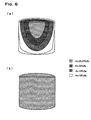
- Figure 6 (a) schematically shows a sectional structure of an ingot made obtained by casting an Au-20 wt% Sn alloy, which has hitherto been considered to have a eutectic composition.
- the composition has no uniformity and alloy layers having different structures were formed.
- a layer made of an Au-20.65 wt% Sn alloy was formed. Therefore, when an Au-20.65 wt% Sn alloy was cast, an alloy ingot having a uniform composition could be obtained as shown in FIG. 6 (b).
- Joining test Next, semiconductor packages were sealed by use of Au-Sn brazing materials having various compositions and thicknesses and the structures of joints were observed.
- the brazing materials used in this test were obtained by rolling Au-Sn alloy ingots of prescribed compositions, which are produced by the melting and casting process, to a prescribed thicknesses in sheet form and blanking the sheets into brazing materials in angular ring form.
- both the base and the cap are made of Kovar and only the cap was plated with gold before joining.
- the brazing material after working was interposed between the base and the cap plated with gold, and joining was performed by heating them to 310°C by use of a conveyor furnace.
- Table 1 shows results of an observation of the structures of joints that depend on the composition and thickness of the Au-Sn brazing materials and the thickness of the gold plating on the cap, which were examined in this embodiment.
- FIGS. 7 to 9 each show a photograph of a sectional structure of a joint observed in this test, respectively, an almost complete eutectic structure (the structure indicated by ⁇ in FIG. 7 and Table 1), a structure in which an Au rich phase is mixed into a eutectic structure (the structure indicated by ⁇ in FIG. 8 and Table 1), and a structure in which an Sn rich phase is mixed into a eutectic structure (the structure indicated by ⁇ in FIG. 9 and Table 1).
- compositions etc. of the brazing materials examined in this embodiment are within the optimum ranges described in the present application and some are outside the ranges, it became apparent from the results of the examination that by ensuring brazing material thicknesses and gold plating thicknesses that fall in optimum ranges for the brazing materials of each composition, it is possible to obtain joints having a good eutectic structure in which an Au rich phase does not occur.
Abstract
Description
- The present invention relates to a method of joining by use of an Au-Sn brazing material, for example, in joining a lead pin to a circuit terminal or sealing a semiconductor package.
- Au-Sn brazing materials are brazing materials in which eutectic structures of Au-Sn alloys are used, and have relatively low melting points (about 280°C). In addition, Au-Sn brazing materials are excellent in corrosion resistance and have the advantage that they do not contain harmful substances such as Pb unlike solders (Sn-37 wt% Pb) that have thitherto been used. Au-Sn brazing materials are widely used in the field of electrical and electronic equipment and have been field proven, for example, as sealing materials for the hermetic sealing of electronic part packages and joining materials for joining lead pins to circuit terminals.
- Although basically a joint formed by an Au-Sn brazing material has an Au-Sn eutectic structure, an Au-Sn alloy phase having a high Au content (hereinafter referred to as an Au rich phase) may sometimes occur partially. This Au rich phase, which is a kind of intermetallic compound, is hard and has a higher melting point than the surrounding Au-Sn eutectic phase. Therefore, this Au rich phase does not dissolve at the melting points of brazing materials and remains as a solid phase. And because the Au rich phase is diverse in size, variations may sometimes be produced in the thickness of a joint. In particular, in a joining method using Au-Sn brazing materials, joining is often performed by plating parts to be joined with gold in order to improve wettability. Owing to the diffusion of gold from this gold plating, the gold content in a joint rises and an Au rich phase becomes apt to occur. Also, in the composition range in which this Au rich phase occurs, the crystal structure becomes coarsened and the solder flow becomes worse, thus posing a problem.
- The present applicant has so far disclosed a sealing method and a joining method that are effective in the above-described uses (Japanese Patent No. 3086086, Japanese Patent Laid-Open No. 2001-176999). In these methods, compared to Au-Sn brazing materials of Au-20 wt% Sn that have hitherto been used, there are used brazing materials having a composition slightly displaced from a eutectic point, in which the gold content is lowered and the Sn content is raised to 20.5 through 21.5%. In these methods, by using a brazing material of low gold content, the composition of the brazing material is prevented from deviating from a eutectic point to the gold side even when the gold content in the brazing material rises during joining due to the diffusion of gold from outside and the occurrence of a gold rich phase is suppressed. A joint formed by these methods has a complete eutectic structure or a eutectic structure containing a small amount of Sn rich phase. Compared to an Au rich phase, an Sn rich phase has a low melting point, exerts a small effect and suppresses the coarsening of a structure by suppressing the occurrence of an Au rich phase. Therefore, by causing a joint having such a structure like an Sn rich phase to be formed, it becomes possible to perform joining in a stable manner.
- The methods disclosed by the present applicant can efficiently form good joints although the methods are simple ones that involve slightly changing the composition of a brazing material to be used. However, according to examinations by the present inventor, although in most cases good joints are obtained by using this brazing material the composition of which is adjusted, in some cases an Au rich phase occurs and satisfactory joints may not be formed. Although the fraction defective itself on that occasion is not high, from the standpoint of ensuring product yield and effective utilization of resources, it is desirable to cause the fraction defective to approach zero as far as possible if this is possible.
- The present invention has been made against the above-described background and has as its object the provision of a joining method using an Au-Sn brazing material that completely suppresses the occurrence of an Au rich phase and can form a homogeneous joint with higher probability.
- The present inventor investigated the reason why joining defects occur with a brazing material in which the Sn content is slightly higher than that of an eutectic composition, and drew the following two conclusions. First, the first conclusion is that a composition (Au-20 wt% Sn) that has hitherto been regarded as a eutectic composition does not show a complete eutectic structure free from an Au rich phase and that a composition a little displaced from this shows a true eutectic structure. This view was obtained from the results of repeated demonstration tests by the present inventor, which will be described later, and Au-Sn alloys show a complete eutectic structure at 20.65 wt% regardless of the cooling rate and the size of cast alloys. It follows that, therefore, even if a brazing material composition is prepared by considering a composition that has hitherto been considered to have a eutectic point, a joint may sometimes deviate from the eutectic point, with the result that an Au rich phase may occur.
- And the second conclusion is that due to the diffusion of gold from the gold plating on the members to be joined, the composition of the joint is such that the gold content becomes higher than the brazing material composition before the joining and the amount of the change in this gold content varies depending on the thickness of the gold plating. That is, the amount of diffused gold increases in proportion to the thickness of the gold plating and the gold content of the joint exceeds an intended gold content, causing a gold rich phase to occur readily. In other words, it might be thought that the reason why joint defects may sometimes occur in conventional methods is that the thickness of the gold plating during joining is too large.
- Supposing that on the basis of the above-described considerations, as a joining method that completely suppresses the occurrence of an Au rich phase, it is preferable to ensure that the composition of a joint is kept in a given range from a true eutectic point to a region displaced slightly from the eutectic point to the Sn side, the present inventor has hit upon the present invention.
- That is, the invention provides a method of joining members to be joined by use of an Au-Sn brazing material, in which joining is performed by adjusting the composition and thickness of the Au-Sn brazing material so that the Sn content of a joint after joining is from 20.65 to 23.5 wt%.
- In the invention, the reason why the composition of the joint is kept in this range is that the true eutectic point of this alloy system is 20.65 wt% Sn, as is apparent from the results of the investigations by the present inventor. The specified upper limit of the Sn content is 23.5 wt%. This is because if the Sn content exceeds 23.5 wt%, the liquidus line temperature of a brazing material becomes a high temperature of not less than 320°C, causing joining defects. As means of adjusting the composition of this joint, the composition of the brazing material is kept in the above-described range when joining is performed without the plating of the members to be joined with gold. On the other hand, when joining is performed after plating the members to be joined with gold, which is usually carried out, it is necessary to appropriately vary the composition and thickness of the brazing material according to the thickness of the gold plating as means of adjusting the composition of this joint, because the composition of the joint varies with the thickness of the gold plating due to the diffusion of gold from the gold plating.
- Therefore, the present inventor examined the relationship between plating thickness and brazing material thickness for each composition of the brazing material to be used in a case where the members to be joined are plated with gold, and studied the conditions under which the composition of a joint after joining falls in the above-described range.
- When brazing materials to be used have an Sn content of 21 wt% to 23 wt%, it is preferable to adjust the thickness of the gold plating in the ranges that satisfy the following equations. The relationship between the thickness of the brazing material and the thickness of the thickness of the gold plating in this case is as shown in FIGS. 1 to 3.
At 21 wt% of Sn y ≤ 0.0126 x At 22 wt% of Sn y ≤ 0.0480 x At 23 wt% of Sn y ≤ 0.0825 x (x: thickness of brazing material, y: thickness of gold plating) - In a case where brazing materials to be used have an Sn content exceeding 24 wt%, it is preferable to adjust the thickness of the gold plating to the region that is defined by two numerical expressions as given below. The reason why the definition by two numerical expressions is necessary like this is that because the Sn content becomes high in these brazing materials, an Sn rich phase occurs in a large amount even when the thickness of the gold plating is increased, thereby requiring an equation in which the effect of an Sn rich phase is considered. The relationship between the thickness of the brazing material and the thickness of the thickness of the gold plating in this case is as shown in FIGS. 4 and 5.
At 24 wt% of Sn 0.0152 x ≤ y ≤ 0.1163 x At 25 wt% of Sn 0.0452 x ≤ y ≤ 0.1492 x (x: thickness of brazing material, y: thickness of gold plating) - The reason why the specified composition range of brazing materials to be used is 21 to 25 wt% Sn is that it is impossible to suppress the occurrence of a gold rich phase if brazing materials of less than 21 wt% Sn are used. If brazing materials of more than 25 wt% Sn are used, there is a possibility that an Sn rich phase may occur in a large amount and besides brazing materials having a high Sn content have poor workability, with the result it is impossible to manufacture brazing materials having precision shapes.
- The thickness of the gold plating differs depending on the kind of members to be joined, and it also differs according to the wettability and the like required even in the case of the same kind of members to be joined. In fixing lead pins or sealing semiconductor packages, gold plating of 0.05 to 3.0 µm is applied. In the sealing of semiconductor packages, the gold plating thickness ranges from small to relatively large sizes. In the invention, therefore, joining is performed in such a manner that the thickness of the gold plating on members to be joined is first determined and after that, the composition and thickness of the brazing material to be used are appropriately selected. Incidentally, for example, in the case of joining of a lead pin, the thickness of the gold plating in the invention is a total of the plating layers separately applied to both of the lead pin and the circuit substrate because joining is performed after both the lead pin and the circuit substrate are plated with gold.
- On the other hand, the composition of a brazing material can be adjusted by controlling the composition of a melt during melting and casting. Also, it is possible to appropriately vary the thickness of a brazing material in the manufacturing process.
- In the joining method of the invention, the conditions and the process may be generally conventional. That is, joining is generally performed in a temperature range of 300 to 320°C under an inert atmosphere of nitrogen or hydrogen gas or vacuum.
- As described above, according to the invention, in the joining process using an Au-Sn brazing material, joining can be completed without causing a gold rich phase to occur in a joint. As a result of this, it is possible to suppress joining defects ascribable to the nonuniformity of the thickness of the joint. According to the invention, it is possible to lower a fraction defective of about 2% in conventional methods to one tenth and hence it is possible to improve product yield and ensure manufacturing efficiency.
- Also, in the invention, there are multiple factors capable of being varied, such as whether plating with gold is performed, the thickness of the gold plating, and the composition and thickness of the brazing material and, therefore, when a brazing material of precision shape is used and when the workability of a brazing material is required, it is possible to use a brazing material of low Sn content. Thus it is possible to carry out a joining method of the invention in a flexible manner.
-
- FIG. 1 is a graph that shows an appropriate region of brazing material thickness and gold plating thickness in a case where an Au-Sn brazing material having an Sn content of 21 wt% is used;
- FIG. 2 is a graph that shows an appropriate region of brazing material thickness and gold plating thickness in a case where an Au-Sn brazing material having an Sn content of 22 wt% is used;
- FIG. 3 is a graph that shows an appropriate region of brazing material thickness and gold plating thickness in a case where an Au-Sn brazing material having an Sn content of 23 wt% is used;
- FIG. 4 is a graph that shows an appropriate region of brazing material thickness and gold plating thickness in a case where an Au-Sn brazing material having an Sn content of 24 wt% is used;
- FIG. 5 is a graph that shows an appropriate region of brazing material thickness and gold plating thickness in a case where an Au-Sn brazing material having an Sn content of 25 wt% is used;
- FIG. 6 (a) is a schematic representation of a sectional structure of an ingot made of an Au-20 wt% Sn alloy;
- FIG. 6 (b) is a schematic representation of a sectional structure of an ingot made of an Au-20.65 wt% Sn alloy;
- FIG. 7 is a photograph of a sectional structure (eutectic structure) of a joint after a joining test;
- FIG. 8 is a photograph of a sectional structure (eutectic structure + Au rich phase) of a joint after a joining test; and
- FIG. 9 is a photograph of a sectional structure (eutectic structure + Sn rich phase) of a joint after a joining test.
-
- Preferred embodiments of the invention will be described below. First, a description will be given of two examples of demonstration tests conducted in order to find a eutectic point of Au-Sn alloys and, at the same time, a description will be given of results of an observation of the structures of joints that were obtained by actually performing package sealing by use of Au-Sn brazing materials of each composition.
Demonstration tests of eutectic point: A true eutectic point of multiple Au-Sn alloys was investigated by melting and casting these Au-Sn alloys and examining the composition distribution and structures of ingots. In the tests, disk-like ingots 30 mm in diameter and 30 mm in height were produced and the composition distribution and structures of the sections of the ingots were investigated. - Figure 6 (a) schematically shows a sectional structure of an ingot made obtained by casting an Au-20 wt% Sn alloy, which has hitherto been considered to have a eutectic composition. In the ingot of this composition, as shown in the figure, the composition has no uniformity and alloy layers having different structures were formed. And in the core of the ingot, a layer made of an Au-20.65 wt% Sn alloy was formed. Therefore, when an Au-20.65 wt% Sn alloy was cast, an alloy ingot having a uniform composition could be obtained as shown in FIG. 6 (b).
Joining test: Next, semiconductor packages were sealed by use of Au-Sn brazing materials having various compositions and thicknesses and the structures of joints were observed. The brazing materials used in this test were obtained by rolling Au-Sn alloy ingots of prescribed compositions, which are produced by the melting and casting process, to a prescribed thicknesses in sheet form and blanking the sheets into brazing materials in angular ring form. In the packages to be jointed, both the base and the cap are made of Kovar and only the cap was plated with gold before joining. And in joining (sealing) the base and the cap, the brazing material after working was interposed between the base and the cap plated with gold, and joining was performed by heating them to 310°C by use of a conveyor furnace. - Table 1 shows results of an observation of the structures of joints that depend on the composition and thickness of the Au-Sn brazing materials and the thickness of the gold plating on the cap, which were examined in this embodiment. FIGS. 7 to 9 each show a photograph of a sectional structure of a joint observed in this test, respectively, an almost complete eutectic structure (the structure indicated by ○ in FIG. 7 and Table 1), a structure in which an Au rich phase is mixed into a eutectic structure (the structure indicated by × in FIG. 8 and Table 1), and a structure in which an Sn rich phase is mixed into a eutectic structure (the structure indicated by Δ in FIG. 9 and Table 1).
Sn content of brazing material Brazing material thickness Gold plating thickness Structure of joint 21 wt% 10 µm 0.05 µm ○ 0.5 µm × 20 µm 0.05 µm ○ 0.5 µm × 30 µm 0.2 µm ○ 0.8 µm × 22 wt% 10 µm 0.3 µm ○ 0.8 µm × 20 µm 0.8 µm ○ 1.2 µm × 30 µm 1.2 µm ○ 1.8 µm × 23 wt% 10 µm 0.6 µm ○ 1.2 µm × 20 µm 1.2 µm ○ 2.0 µm × 30 µm 2.1 µm ○ 3.0 µm × 24 wt% 10 µm 0.5 µm Δ 1.0 µm ○ 2.0 µm × 20 µm 0.2 µm Δ 1.2 µm ○ 3.0 µm × 30 µm 0.2 µm Δ 2.0 µm ○ 4.0 µm × 25 wt% 10 µm 0.1 µm Δ 0.8 µm ○ 2.0 µm × 20 µm 0.4 µm Δ 2.0 µm ○ 3.5 µm × 30 µm 0.8 µm Δ 3.0 µm ○ 5.0 µm × ○ Eutectic structure × Eutectic structure + Au rich phase Δ Eutectic structure + Excessive Sn rich phase - Although some of the compositions etc. of the brazing materials examined in this embodiment are within the optimum ranges described in the present application and some are outside the ranges, it became apparent from the results of the examination that by ensuring brazing material thicknesses and gold plating thicknesses that fall in optimum ranges for the brazing materials of each composition, it is possible to obtain joints having a good eutectic structure in which an Au rich phase does not occur.
Claims (2)
- A method of joining members to be joined by use of an Au-Sn brazing material,
wherein the composition and thickness of the Au-Sn brazing material are adjusted so that the Sn content of the joint after the joining is from 20.65 to 23.5 wt%. - The method according to claim 1, comprising plating joint surfaces of the members to be joined with gold prior to the joining,
wherein the composition and thickness of the brazing material are adjusted so that the following relationships hold among the composition and the thickness of the Au-Sn brazing material and the thickness of the gold plating:At 21 wt% of Sn y ≤ 0.0126 x At 22 wt% of Sn y ≤ 0.0480 x At 23 wt% of Sn y ≤ 0.0825 x At 24 wt% of Sn 0.0152 x ≤ y ≤ 0.1163 x At 25 wt% of Sn 0.0452 x ≤ y ≤ 0.1492 x
Applications Claiming Priority (2)
| Application Number | Priority Date | Filing Date | Title |
|---|---|---|---|
| JP2004044600 | 2004-02-20 | ||
| JP2004044600 | 2004-02-20 |
Publications (2)
| Publication Number | Publication Date |
|---|---|
| EP1591191A1 true EP1591191A1 (en) | 2005-11-02 |
| EP1591191B1 EP1591191B1 (en) | 2008-04-02 |
Family
ID=34858067
Family Applications (1)
| Application Number | Title | Priority Date | Filing Date |
|---|---|---|---|
| EP05002819A Active EP1591191B1 (en) | 2004-02-20 | 2005-02-10 | Joining method by Au-Sn brazing material, its thickness being i.a. dependent on the Sn-content |
Country Status (3)
| Country | Link |
|---|---|
| US (1) | US7114644B2 (en) |
| EP (1) | EP1591191B1 (en) |
| DE (1) | DE602005005733T2 (en) |
Families Citing this family (3)
| Publication number | Priority date | Publication date | Assignee | Title |
|---|---|---|---|---|
| JP4285753B2 (en) * | 2004-06-21 | 2009-06-24 | 田中貴金属工業株式会社 | Hermetic seal cover and method for manufacturing the same |
| US8110022B2 (en) * | 2009-04-16 | 2012-02-07 | Genesis Fueltech, Inc. | Hydrogen purifier module and method for forming the same |
| JP5708692B2 (en) | 2013-03-28 | 2015-04-30 | Tdk株式会社 | Junction structure for electronic device and electronic device |
Citations (4)
| Publication number | Priority date | Publication date | Assignee | Title |
|---|---|---|---|---|
| JPH06126485A (en) * | 1992-10-19 | 1994-05-10 | Tanaka Kikinzoku Kogyo Kk | Brazing filler metal for lead pin |
| US5794839A (en) * | 1994-08-01 | 1998-08-18 | Nippondenso Co., Ltd. | Bonding material and bonding method for electric element |
| USH1934H1 (en) * | 1992-05-01 | 2001-01-02 | Lucent Technologies, Inc. | Gold-tin solder suitable for self-aligning applications |
| US20020190106A1 (en) * | 2000-11-27 | 2002-12-19 | Shozaburo Iwai | Method for hermetic sealing of electronic parts |
Family Cites Families (6)
| Publication number | Priority date | Publication date | Assignee | Title |
|---|---|---|---|---|
| US5234153A (en) * | 1992-08-28 | 1993-08-10 | At&T Bell Laboratories | Permanent metallic bonding method |
| TWI248384B (en) * | 2000-06-12 | 2006-02-01 | Hitachi Ltd | Electronic device |
| JP4416373B2 (en) * | 2002-03-08 | 2010-02-17 | 株式会社日立製作所 | Electronics |
| US7187496B2 (en) * | 2002-03-14 | 2007-03-06 | Tdk Corporation | Manufacturing method of optical device, optical device, manufacturing method of faraday rotator, and optical communication system |
| JP2004031696A (en) * | 2002-06-26 | 2004-01-29 | Kyocera Corp | Thermoelectric module and method for manufacturing the same |
| JP4014549B2 (en) * | 2003-09-18 | 2007-11-28 | 富士電機システムズ株式会社 | Heat sink and manufacturing method thereof |
-
2005
- 2005-02-10 DE DE602005005733T patent/DE602005005733T2/en active Active
- 2005-02-10 EP EP05002819A patent/EP1591191B1/en active Active
- 2005-02-11 US US11/055,945 patent/US7114644B2/en active Active
Patent Citations (4)
| Publication number | Priority date | Publication date | Assignee | Title |
|---|---|---|---|---|
| USH1934H1 (en) * | 1992-05-01 | 2001-01-02 | Lucent Technologies, Inc. | Gold-tin solder suitable for self-aligning applications |
| JPH06126485A (en) * | 1992-10-19 | 1994-05-10 | Tanaka Kikinzoku Kogyo Kk | Brazing filler metal for lead pin |
| US5794839A (en) * | 1994-08-01 | 1998-08-18 | Nippondenso Co., Ltd. | Bonding material and bonding method for electric element |
| US20020190106A1 (en) * | 2000-11-27 | 2002-12-19 | Shozaburo Iwai | Method for hermetic sealing of electronic parts |
Non-Patent Citations (1)
| Title |
|---|
| PATENT ABSTRACTS OF JAPAN vol. 018, no. 418 (M - 1650) 5 August 1994 (1994-08-05) * |
Also Published As
| Publication number | Publication date |
|---|---|
| EP1591191B1 (en) | 2008-04-02 |
| DE602005005733D1 (en) | 2008-05-15 |
| US20050184135A1 (en) | 2005-08-25 |
| DE602005005733T2 (en) | 2009-05-28 |
| US7114644B2 (en) | 2006-10-03 |
Similar Documents
| Publication | Publication Date | Title |
|---|---|---|
| US6179935B1 (en) | Solder alloys | |
| US6689488B2 (en) | Lead-free solder and solder joint | |
| US10157877B2 (en) | Semiconductor device and manufacturing method of semiconductor device | |
| JP5186719B2 (en) | Ceramic wiring board, manufacturing method thereof, and semiconductor module | |
| EP3381601B1 (en) | Solder alloy, solder ball and solder joint | |
| EP2474383B1 (en) | Lead-free solder alloy, joining member and manufacturing method thereof, and electronic component | |
| US20080118761A1 (en) | Modified solder alloys for electrical interconnects, methods of production and uses thereof | |
| EP1429884B1 (en) | Improved compositions, methods and devices for high temperature lead-free solder | |
| EP3492217B1 (en) | Solder material | |
| JP4769469B2 (en) | Bonding method using Au-Sn brazing material | |
| EP1798763B1 (en) | Semiconductor device and bonding method therefor | |
| US20090286093A1 (en) | Lead-free solder | |
| EP2322316A1 (en) | Au-Ga-In BRAZING FILLER METAL | |
| US7114644B2 (en) | Joining method by Au-Sn brazing material | |
| EP3031567A1 (en) | Lead-free solder alloy | |
| WO2007075763A1 (en) | Modified and doped solder alloys for electrical interconnects, methods of production and uses thereof | |
| EP3573100B1 (en) | Solder bonding method and solder joint | |
| US20110108996A1 (en) | Joint structure, joining material and method for producing joining material | |
| US20230068294A1 (en) | Lead-Free and Antimony-Free Solder Alloy, Solder Ball, and Solder Joint | |
| EP4105349A1 (en) | Lead-free and antimony-free solder alloy, solder ball, and solder joint | |
| WO2010122795A1 (en) | Semiconductor device | |
| US20220297243A1 (en) | Solder paste and solder bonded body | |
| EP0242525A1 (en) | Improved wetting of low melting temperature solders by surface active additions | |
| US20040096688A1 (en) | Lead-free joining material and joining method using the same | |
| JPH081372A (en) | Composite soldering material and its manufacture |
Legal Events
| Date | Code | Title | Description |
|---|---|---|---|
| PUAI | Public reference made under article 153(3) epc to a published international application that has entered the european phase |
Free format text: ORIGINAL CODE: 0009012 |
|
| AK | Designated contracting states |
Kind code of ref document: A1 Designated state(s): AT BE BG CH CY CZ DE DK EE ES FI FR GB GR HU IE IS IT LI LT LU MC NL PL PT RO SE SI SK TR |
|
| AX | Request for extension of the european patent |
Extension state: AL BA HR LV MK YU |
|
| 17P | Request for examination filed |
Effective date: 20051124 |
|
| AKX | Designation fees paid |
Designated state(s): CH DE FR GB IT LI |
|
| GRAP | Despatch of communication of intention to grant a patent |
Free format text: ORIGINAL CODE: EPIDOSNIGR1 |
|
| GRAS | Grant fee paid |
Free format text: ORIGINAL CODE: EPIDOSNIGR3 |
|
| 17Q | First examination report despatched |
Effective date: 20051213 |
|
| RAP1 | Party data changed (applicant data changed or rights of an application transferred) |
Owner name: TANAKA KIKINZOKU KOGYO K.K. |
|
| GRAA | (expected) grant |
Free format text: ORIGINAL CODE: 0009210 |
|
| AK | Designated contracting states |
Kind code of ref document: B1 Designated state(s): CH DE FR GB IT LI |
|
| REG | Reference to a national code |
Ref country code: GB Ref legal event code: FG4D |
|
| REG | Reference to a national code |
Ref country code: CH Ref legal event code: EP |
|
| REF | Corresponds to: |
Ref document number: 602005005733 Country of ref document: DE Date of ref document: 20080515 Kind code of ref document: P |
|
| REG | Reference to a national code |
Ref country code: CH Ref legal event code: NV Representative=s name: BOHEST AG |
|
| ET | Fr: translation filed | ||
| PLBE | No opposition filed within time limit |
Free format text: ORIGINAL CODE: 0009261 |
|
| STAA | Information on the status of an ep patent application or granted ep patent |
Free format text: STATUS: NO OPPOSITION FILED WITHIN TIME LIMIT |
|
| 26N | No opposition filed |
Effective date: 20090106 |
|
| REG | Reference to a national code |
Ref country code: CH Ref legal event code: PCAR Free format text: NEW ADDRESS: HOLBEINSTRASSE 36-38, 4051 BASEL (CH) |
|
| REG | Reference to a national code |
Ref country code: FR Ref legal event code: PLFP Year of fee payment: 12 |
|
| REG | Reference to a national code |
Ref country code: FR Ref legal event code: PLFP Year of fee payment: 13 |
|
| REG | Reference to a national code |
Ref country code: DE Ref legal event code: R082 Ref document number: 602005005733 Country of ref document: DE Representative=s name: SCHMITT-NILSON SCHRAUD WAIBEL WOHLFROM PATENTA, DE |
|
| REG | Reference to a national code |
Ref country code: FR Ref legal event code: PLFP Year of fee payment: 14 |
|
| PGFP | Annual fee paid to national office [announced via postgrant information from national office to epo] |
Ref country code: FR Payment date: 20230220 Year of fee payment: 19 Ref country code: CH Payment date: 20230307 Year of fee payment: 19 |
|
| PGFP | Annual fee paid to national office [announced via postgrant information from national office to epo] |
Ref country code: IT Payment date: 20230223 Year of fee payment: 19 Ref country code: GB Payment date: 20230220 Year of fee payment: 19 Ref country code: DE Payment date: 20230216 Year of fee payment: 19 |