EP1591075B1 - Planungsverfahren und -vorrichtung für Knieimplantationen - Google Patents
Planungsverfahren und -vorrichtung für Knieimplantationen Download PDFInfo
- Publication number
- EP1591075B1 EP1591075B1 EP04009937A EP04009937A EP1591075B1 EP 1591075 B1 EP1591075 B1 EP 1591075B1 EP 04009937 A EP04009937 A EP 04009937A EP 04009937 A EP04009937 A EP 04009937A EP 1591075 B1 EP1591075 B1 EP 1591075B1
- Authority
- EP
- European Patent Office
- Prior art keywords
- planning
- anatomy
- genicular
- patella
- data
- Prior art date
- Legal status (The legal status is an assumption and is not a legal conclusion. Google has not performed a legal analysis and makes no representation as to the accuracy of the status listed.)
- Expired - Lifetime
Links
Images

Classifications
-
- A—HUMAN NECESSITIES
- A61—MEDICAL OR VETERINARY SCIENCE; HYGIENE
- A61B—DIAGNOSIS; SURGERY; IDENTIFICATION
- A61B5/00—Measuring for diagnostic purposes; Identification of persons
- A61B5/45—For evaluating or diagnosing the musculoskeletal system or teeth
- A61B5/4538—Evaluating a particular part of the muscoloskeletal system or a particular medical condition
- A61B5/4585—Evaluating the knee
-
- A—HUMAN NECESSITIES
- A61—MEDICAL OR VETERINARY SCIENCE; HYGIENE
- A61B—DIAGNOSIS; SURGERY; IDENTIFICATION
- A61B34/00—Computer-aided surgery; Manipulators or robots specially adapted for use in surgery
- A61B34/10—Computer-aided planning, simulation or modelling of surgical operations
-
- A—HUMAN NECESSITIES
- A61—MEDICAL OR VETERINARY SCIENCE; HYGIENE
- A61B—DIAGNOSIS; SURGERY; IDENTIFICATION
- A61B5/00—Measuring for diagnostic purposes; Identification of persons
- A61B5/103—Measuring devices for testing the shape, pattern, colour, size or movement of the body or parts thereof, for diagnostic purposes
- A61B5/107—Measuring physical dimensions, e.g. size of the entire body or parts thereof
- A61B5/1076—Measuring physical dimensions, e.g. size of the entire body or parts thereof for measuring dimensions inside body cavities, e.g. using catheters
-
- A—HUMAN NECESSITIES
- A61—MEDICAL OR VETERINARY SCIENCE; HYGIENE
- A61B—DIAGNOSIS; SURGERY; IDENTIFICATION
- A61B5/00—Measuring for diagnostic purposes; Identification of persons
- A61B5/103—Measuring devices for testing the shape, pattern, colour, size or movement of the body or parts thereof, for diagnostic purposes
- A61B5/11—Measuring movement of the entire body or parts thereof, e.g. head or hand tremor or mobility of a limb
- A61B5/1113—Local tracking of patients, e.g. in a hospital or private home
- A61B5/1114—Tracking parts of the body
-
- A—HUMAN NECESSITIES
- A61—MEDICAL OR VETERINARY SCIENCE; HYGIENE
- A61B—DIAGNOSIS; SURGERY; IDENTIFICATION
- A61B5/00—Measuring for diagnostic purposes; Identification of persons
- A61B5/103—Measuring devices for testing the shape, pattern, colour, size or movement of the body or parts thereof, for diagnostic purposes
- A61B5/11—Measuring movement of the entire body or parts thereof, e.g. head or hand tremor or mobility of a limb
- A61B5/1126—Measuring movement of the entire body or parts thereof, e.g. head or hand tremor or mobility of a limb using a particular sensing technique
- A61B5/1127—Measuring movement of the entire body or parts thereof, e.g. head or hand tremor or mobility of a limb using a particular sensing technique using markers
-
- A—HUMAN NECESSITIES
- A61—MEDICAL OR VETERINARY SCIENCE; HYGIENE
- A61B—DIAGNOSIS; SURGERY; IDENTIFICATION
- A61B90/00—Instruments, implements or accessories specially adapted for surgery or diagnosis and not covered by any of the groups A61B1/00 - A61B50/00, e.g. for luxation treatment or for protecting wound edges
- A61B90/36—Image-producing devices or illumination devices not otherwise provided for
-
- A—HUMAN NECESSITIES
- A61—MEDICAL OR VETERINARY SCIENCE; HYGIENE
- A61B—DIAGNOSIS; SURGERY; IDENTIFICATION
- A61B34/00—Computer-aided surgery; Manipulators or robots specially adapted for use in surgery
- A61B34/10—Computer-aided planning, simulation or modelling of surgical operations
- A61B2034/101—Computer-aided simulation of surgical operations
- A61B2034/102—Modelling of surgical devices, implants or prosthesis
-
- A—HUMAN NECESSITIES
- A61—MEDICAL OR VETERINARY SCIENCE; HYGIENE
- A61B—DIAGNOSIS; SURGERY; IDENTIFICATION
- A61B34/00—Computer-aided surgery; Manipulators or robots specially adapted for use in surgery
- A61B34/10—Computer-aided planning, simulation or modelling of surgical operations
- A61B2034/101—Computer-aided simulation of surgical operations
- A61B2034/105—Modelling of the patient, e.g. for ligaments or bones
-
- A—HUMAN NECESSITIES
- A61—MEDICAL OR VETERINARY SCIENCE; HYGIENE
- A61B—DIAGNOSIS; SURGERY; IDENTIFICATION
- A61B34/00—Computer-aided surgery; Manipulators or robots specially adapted for use in surgery
- A61B34/10—Computer-aided planning, simulation or modelling of surgical operations
- A61B2034/107—Visualisation of planned trajectories or target regions
-
- A—HUMAN NECESSITIES
- A61—MEDICAL OR VETERINARY SCIENCE; HYGIENE
- A61B—DIAGNOSIS; SURGERY; IDENTIFICATION
- A61B34/00—Computer-aided surgery; Manipulators or robots specially adapted for use in surgery
- A61B34/20—Surgical navigation systems; Devices for tracking or guiding surgical instruments, e.g. for frameless stereotaxis
- A61B2034/2046—Tracking techniques
- A61B2034/2051—Electromagnetic tracking systems
-
- A—HUMAN NECESSITIES
- A61—MEDICAL OR VETERINARY SCIENCE; HYGIENE
- A61B—DIAGNOSIS; SURGERY; IDENTIFICATION
- A61B34/00—Computer-aided surgery; Manipulators or robots specially adapted for use in surgery
- A61B34/20—Surgical navigation systems; Devices for tracking or guiding surgical instruments, e.g. for frameless stereotaxis
- A61B2034/2046—Tracking techniques
- A61B2034/2055—Optical tracking systems
-
- A—HUMAN NECESSITIES
- A61—MEDICAL OR VETERINARY SCIENCE; HYGIENE
- A61B—DIAGNOSIS; SURGERY; IDENTIFICATION
- A61B34/00—Computer-aided surgery; Manipulators or robots specially adapted for use in surgery
- A61B34/20—Surgical navigation systems; Devices for tracking or guiding surgical instruments, e.g. for frameless stereotaxis
- A61B2034/2068—Surgical navigation systems; Devices for tracking or guiding surgical instruments, e.g. for frameless stereotaxis using pointers, e.g. pointers having reference marks for determining coordinates of body points
-
- A—HUMAN NECESSITIES
- A61—MEDICAL OR VETERINARY SCIENCE; HYGIENE
- A61B—DIAGNOSIS; SURGERY; IDENTIFICATION
- A61B34/00—Computer-aided surgery; Manipulators or robots specially adapted for use in surgery
- A61B34/25—User interfaces for surgical systems
- A61B2034/252—User interfaces for surgical systems indicating steps of a surgical procedure
-
- A—HUMAN NECESSITIES
- A61—MEDICAL OR VETERINARY SCIENCE; HYGIENE
- A61B—DIAGNOSIS; SURGERY; IDENTIFICATION
- A61B90/00—Instruments, implements or accessories specially adapted for surgery or diagnosis and not covered by any of the groups A61B1/00 - A61B50/00, e.g. for luxation treatment or for protecting wound edges
- A61B90/36—Image-producing devices or illumination devices not otherwise provided for
- A61B90/37—Surgical systems with images on a monitor during operation
- A61B2090/376—Surgical systems with images on a monitor during operation using X-rays, e.g. fluoroscopy
-
- A—HUMAN NECESSITIES
- A61—MEDICAL OR VETERINARY SCIENCE; HYGIENE
- A61B—DIAGNOSIS; SURGERY; IDENTIFICATION
- A61B34/00—Computer-aided surgery; Manipulators or robots specially adapted for use in surgery
- A61B34/20—Surgical navigation systems; Devices for tracking or guiding surgical instruments, e.g. for frameless stereotaxis
-
- A—HUMAN NECESSITIES
- A61—MEDICAL OR VETERINARY SCIENCE; HYGIENE
- A61B—DIAGNOSIS; SURGERY; IDENTIFICATION
- A61B34/00—Computer-aided surgery; Manipulators or robots specially adapted for use in surgery
- A61B34/25—User interfaces for surgical systems
-
- A—HUMAN NECESSITIES
- A61—MEDICAL OR VETERINARY SCIENCE; HYGIENE
- A61B—DIAGNOSIS; SURGERY; IDENTIFICATION
- A61B5/00—Measuring for diagnostic purposes; Identification of persons
- A61B5/45—For evaluating or diagnosing the musculoskeletal system or teeth
- A61B5/4528—Joints
Definitions
- the invention relates to a planning method and a planning device for knee implantation.
- an implant When placing knee implants, an implant should be attached to the remaining bone in such a way that no excessive or unilaterally high loads occur later during the movement, which can lead to a sensation of pain.
- patella tracking In order to take these boundary conditions into account in the planning of the implantation, so-called patella tracking is already conventionally carried out in a very simple design.
- tracking or “motion-capturing” in the present text, it refers to the tracking of the movement of a body with the aid of motion detection devices.
- active radiator or passive reflectors can be tracked or tracked to detect their whereabouts at a given time (pre- / intra- / post-operative) or their trajectory and thus the place or to be able to determine the path of the body.
- passive marker reflectors that emit infrared light that is detected by two infrared light cameras, wherein spatial locations or spatial movements of the body can be determined by stereoscopic viewing.
- reference arrays (arrangements of, for example, three of the above-mentioned markers) are attached to this as well as the femur and possibly also tibial bone, all three bones are registered, and one track is tracked or just a few single points of the patella to detect their orbit opposite the femur bone.
- a method is to be provided which allows for optimal planning and thus also provides for the position and path of the patella after placing the implant for favorable conditions.
- the advantages of the present invention are based on the fact that the patient's knee anatomy is detected spatially or the surface contour, so that touches or overlaps between the implant and the parts of the knee anatomy can be detected and simulated much more extensively and with much greater significance. Based on these results, a possible problem with a currently proposed implant positioning can be detected much more precisely than before, and the positioning can be adjusted until the problem no longer occurs.
- the invention is also part of the patella tracking functionality of a surgical computer-aided planning system.
- the general idea is also to follow the movement of the patella towards the femur bone, whereby as a postoperative result the patella or a patellar implant should slide in such a way on the femur or on the femoral implant that the patient at the posterior or anterior part of the patella no Feeling pain.
- This result can be achieved by ensuring that the patella runs anatomically after implantation and does not place unnatural stresses on the patella be applied. This is true even if the patella sliding surface has been replaced by an implant.
- the spatial data of the shape of the patient's knee anatomy are detected by a surface scan by means of a tracked scanning instrument, in particular by means of a navigated pointer of a surgical navigation system.
- a surface scan by means of a tracked scanning instrument, in particular by means of a navigated pointer of a surgical navigation system.
- Such an embodiment makes the whole environment very simple and clear and eliminates the need for complicated and expensive surface scanning apparatus. It is particularly advantageous in such scans, when those areas of the patient knee anatomy are scanned or detected, which later also touch or run against each other or have contact, so the contact or running surfaces of the knee anatomy parts.
- the scans may be performed pre-operatively or intraoperatively.
- the movement recording can also be post-operative, if, for example, an implanted reference marker remains in the said bone of the patient and is measured, for example, in a magnetic field. If the position of the reference marker to the bone image is known, such as by an intraoperatively performed referencing, the recorded movement can be compared with the pre- or intraoperatively recorded movements and analyzed.
- the touches or overlaps are considered to be uncritical if they indicate substantially symmetrical contacts between the parts of the knee anatomy or avoidance of patella alta or patella bacha.
- the adaptation of the positioning, the shape or orientation of the implant according to the invention can be done automatically by the computer-aided planning system. This is not the only option. Rather, it is also possible according to the invention to have the computer-aided planning system output data on at least one possible adaptation, wherein the suitable adaptation can then be confirmed or selected by operator input. A third option is then an adjustment by the operator based on the acquired touch or crossover data.
- One or more of these illustrated bodies may be included in the image output.
- a variety of display options are conceivable, for example, the detected touch or overlap data monochrome, monochrome with different shades or different colors, depending on the intensity of the touch or
- the method according to the invention is also suitable in those cases where band corrections take place.
- the change in patellar movement can be determined after a knee length correction and optionally taken into account in the adjustment.
- the movement of the patella in the original state of the knee joint is recorded when the knee is flexed and stretched.
- This can be done pre- and / or intraoperatively, with reference marker arrangements being placed on the patella and on the articular ends of the femur and tibia and followed by a camera-based or magnetic tracking system, for example.
- a camera-based or magnetic tracking system for example.
- Shape after being captured This happens here, for example, in that the surfaces are traversed with the tip of a likewise tracked Abtastinstruments, so that in the planning system, the outer contour can be stored in terms of area as a record. Now, the planning system knows the natural movement between the patella and the remaining joint parts with each other, and it knows the shape of the touching and running surfaces in this anatomical state.
- the planning system also includes data for knee implants, particularly data on the shape of such knee implants. If, at the planning station, virtually a part of the knee anatomy, for example of the femoral condyle, is replaced by such a knee implant, e.g.
- the contact or walking surfaces can be calculated from the resulting touches or overlaps and highlighted in an image to provide the surgeon with information about how the position of the implant affects the tension and kinematics of the patella , In other words, the recorded movement of the patella is represented, for example, in an implant positioning planning view with respect to the femur bone and a planned femur implant position.
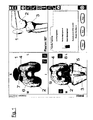
- FIG. 1 (and in FIG. 2 1) denotes the patella, the reference numeral 2 the femur bone and the reference numeral 3 the tibia.
- FIG. 1 denotes the patella
- the reference numeral 2 the femur bone
- the reference numeral 3 the tibia.
- right above an angular position of the knee joint is shown in a side view, including one input / output field of the software.
- the image shows the femur bone with patella and in FIG. 1
- the lower left shows the femur and tibia with implants.
- the image on the top right also shows the femoral implant.
- FIG. 1 Left top in FIG. 1 the position of the patella 1 over the femur bone 2 is shown.
- an implant 4 is arranged on the femur 2, on the femur 2, an implant 4 is arranged.
- On the implant 4 as well as on the patella is indicated by different shading, where a strong contact (impingement) and where a weaker contact takes place, when the knee is moved with the implant set.
- the darker areas indicate, as in the legend is shown on the lower right, a stronger touch or a stronger contact than the brighter places; a dark spot on the femoral implant is designated by the reference numeral 6, a bright spot on the patella by the reference numeral 7.
- the positioning of the implant can now be virtually adapted, for example by a virtual displacement to the anterior or posterior, medial or lateral, or in a rotation. This can be done automatically due to the contact strength information provided by the planning system or "by hand" through user intervention. At the end, one will find an implant position where the contact intensities are within a desired range.
- the contact intensity may here be e.g. a pressure and / or the direction of pressure on the patella.
- the intensity can e.g. be determined selectively, over an area or volume-related.
- FIG. 2 shows illustrations for a specific application in the context of the present invention. Namely, during the operation, a change in the kinematics or leg axis, in particular z. As an extension of the knee ligaments, is also expected that the career of the patella changes. To account for these changes in position of the patella, the user of the system according to the invention after the changes to the ligaments can again record the movement of the parts of the knee anatomy by means of the tracking or motion capturing method and make these data available to the planning station. When a movement sequence is simulated again, it becomes clear how the position and trajectory of the patella changes, what in FIG. 2 at the bottom left, the reference numeral 1 'indicating the original and the reference numeral 1 the new position of the patella after the band extension.
- arrows and text indicate how the situation has changed, such as a shift of 4.5 mm to the left, 3.2 mm to the top, and a rotation of 2 ° to the opposite clockwise.
- the operator can then choose whether to select the initial or the current new pathway as the basis for the implant positioning. Then again the contact intensity is shown (see FIG. 1 ) and the optimal implant position is determined.
- the determined planning data can be used to determine the positioning of a device (gauge) with the aid of which the bones are removed so that the actual implant can be placed and fastened in the optimal position.
- the motion recording can be done post-operatively again, for example, if an implanted reference marker remains in the patient's bones, e.g. measured in a magnetic field. If the position of the reference marker to the bone image is known, such as by a referencing performed intraoperatively, the recorded movement can be compared with the pre- or intraoperatively recorded movements and analyzed.
Landscapes
- Health & Medical Sciences (AREA)
- Life Sciences & Earth Sciences (AREA)
- Surgery (AREA)
- Engineering & Computer Science (AREA)
- General Health & Medical Sciences (AREA)
- Public Health (AREA)
- Veterinary Medicine (AREA)
- Animal Behavior & Ethology (AREA)
- Biomedical Technology (AREA)
- Heart & Thoracic Surgery (AREA)
- Medical Informatics (AREA)
- Molecular Biology (AREA)
- Oral & Maxillofacial Surgery (AREA)
- Pathology (AREA)
- Physics & Mathematics (AREA)
- Dentistry (AREA)
- Biophysics (AREA)
- Physiology (AREA)
- Nuclear Medicine, Radiotherapy & Molecular Imaging (AREA)
- Orthopedic Medicine & Surgery (AREA)
- Rheumatology (AREA)
- Physical Education & Sports Medicine (AREA)
- Robotics (AREA)
- Prostheses (AREA)
- Surgical Instruments (AREA)
- Apparatus For Radiation Diagnosis (AREA)
- Processing Or Creating Images (AREA)
- Measurement Of The Respiration, Hearing Ability, Form, And Blood Characteristics Of Living Organisms (AREA)
Description
- Die Erfindung betrifft ein Planungsverfahren und eine Planungsvorrichtung für Knieimplantationen. Beim Setzen von Knieimplantaten sollte ein Implantat in einer solchen Weise am verbleibenden Knochen angebracht werden, dass später auch bei der Bewegung keine zu hohen bzw. einseitig zu hohen Belastungen auftreten, die zu einem Schmerzempfinden führen können. Insbesondere möchte man die richtige Positionierung der Patella sicherstellen, um deren Lauf auch bei eingesetztem Implantat optimal gestalten zu können.
- Um diese Randbedingungen bei der Planung der Implantation zu berücksichtigen, wird schon herkömmlicherweise ein sogenanntes Patella-Tracking in einer sehr einfachen Ausführung durchgeführt. Wenn im vorliegenden Text von "Tracking" oder "Motion-Capturing" die Rede ist, so ist damit ganz allgemein die Verfolgung der Bewegung eines Körpers mit Hilfe von Bewegungserfassungseinrichtungen gemeint. Dabei können insbesondere ein Körper selbst oder an ihm angebrachte aktive Abstrahler oder passive Reflektoren verfolgt bzw. getrackt werden, um deren Aufenthaltsort zu einem bestimmten Zeitpunkt (prä-/intra-/post operativ) bzw. ihre Bahn zu erfassen und somit auch den Ort oder die Bahn des Körpers bestimmen zu können. Bei einem Ausführungsbeispiel handelt es sich beispielsweise um passive Marker-Reflektoren, die Infrarotlicht zurückstrahlen, welches durch zwei Infrarotlichtkameras erfasst wird, wobei durch die stereoskopische Betrachtung räumliche Orte bzw. räumliche Bewegungen des Körpers bestimmt werden können.
- Bei der oben genannten, herkömmlichen Bewegungserfassung für die Patella werden an dieser sowie an dem Femur- und evtl. auch Tibiaknochen Referenzanordnungen (Anordnungen von beispielsweise drei der oben genannten Marker) angebracht, alle drei Knochen werden registriert, und man verfolgt bzw. trackt einen einzigen oder nur wenige einzelne Punkte der Patella, um deren Bahn gegenüber dem Femurknochen zu erfassen.
- Der Nachteil dieser bekannten Verfahren liegt einfach in ihrer geringen Aussagekraft über die später zu erwartenden relativen Bewegungen und Berührungen der einzelnen Gelenkteile. Das punktweise Tracking bzw. Motion-Capturing für einzelne Punkte der Patella ist unzureichend für eine realitätsnahe Simulation der Endbedingungen und damit auch nicht ausreichend für eine optimale Planung.
- Es ist die Aufgabe der vorliegenden Erfindung, ein Planungsverfahren und eine Planungsvorrichtung für Knieimplantationen vorzustellen, welche die vorgenannten Nachteile des Standes der Technik überwinden. Insbesondere soll ein Verfahren bereitgestellt werden, welches eine optimale Planung ermöglicht und somit auch hinsichtlich der Lage und Bahn der Patella nach dem setzen des Implantats für günstige Verhältnisse sorgt.
- Diese Aufgabe wird durch ein Planungsverfahren für Knieimplantationen gelöst, wie es im Anspruch 1 beschrieben ist, sowie durch eine Vorrichtung gemäß Anspruch 11. Die Unteransprüche beschreiben bevorzugte Ausführungsformen der Erfindung.
- Die Vorteile der vorliegenden Erfindung beruhen darauf, dass die Patienten-Knieanatomie räumlich bzw. der Oberflächenkontur nach erfasst wird, so dass Berührungen oder Überschneidungen zwischen Implantat und den Teilen der Knieanatomie sehr viel umfänglicher und mit sehr viel höherer Aussagekraft erfasst und simuliert werden können. Auf der Basis dieser Ergebnisse lässt sich dann sehr viel präziser als bisher ein mögliches Problem bei einer momentan vorgeschlagenen Implantatpositionierung erkennen, und die Positionierung lässt sich anpassen, bis das Problem nicht mehr auftritt.
- Mit anderen Worten ist die Erfindung auch ein Teil der Patella-Tracking-Funktionalität eines chirurgischen computergestützten Planungssystems. Die allgemeine Idee liegt auch darin, die Bewegung der Patella zum Femurknochen hin zu verfolgen, wobei als postoperatives Resultat die Patella oder ein Patellaimplantat in einer solchen Weise am Femur oder an dem Femurimplantat gleiten sollte, dass der Patient am hinteren oder vorderen Teil der Patella keinen Schmerz verspürt. Dieses Resultat kann dadurch erzielt werden, dass sichergestellt wird, dass die Patella nach der Implantation anatomisch läuft und keine unnatürlichen Belastungen auf die Patella aufgebracht werden. Das gilt auch wenn die Patella-Gleitfläche durch ein Implantat ersetzt wurde.
- Gemäß einer bevorzugten Ausführungsform des erfindungsgemäßen Verfahrens werden die räumlichen Daten der Gestalt der Patienten-Knieanatomie durch eine Oberflächen-Abtastung mittels eines getrackten Abtastinstruments erfasst, insbesondere mittels eines navigierten Pointers eines chirurgischen Navigationssystems. Eine solche Ausführungsform gestaltet das gesamte Umfeld sehr einfach und übersichtlich und macht die Verwendung komplizierter und teurer Apparate für die Oberflächen-Abtastung überflüssig. Von besonderem Vorteil ist es bei solchen Abtastungen, wenn diejenigen Flächen der Patienten-Knieanatomie abgetastet bzw. erfasst werden, welche sich später auch berühren bzw. aneinander laufen oder Kontakt haben, also die Kontakt- bzw. Laufflächen der Knie-Anatomieteile. Es kann aber auch die Oberflächenabtastung erst erfolgen, wenn bereits eine vollständige Bewegung des Beins durchgeführt wurde und dabei lediglich die relative Bewegung zwischen den bereits angebrachten Referenzsystemen aufgezeichnet wurde. Dieses Vorgehen wird weiter unten noch genauer erklärt.
- Es soll im Rahmen der vorliegenden Erfindung aber nicht völlig ausgeschlossen werden, dass auch hochgenaue Oberflächen-Abtastungen mit technischer Hilfe durchgeführt werden. So ist es gemäß einer anderen Ausführungsform der vorliegenden Erfindung möglich, die räumlichen Daten der Gestalt der Patienten-Knieanatomie durch eine Oberflächen-Abtastungen mit Hilfe eines Schichtbild-Erfassungsverfahrens, insbesondere eines CT-Scans zu erfassen.
- Die genannten Abtastungen können prä-operativ oder intraoperativ erfolgen. Die Bewegungsaufzeichnung kann aber auch post-operativ erfolgen, wenn beispielsweise ein implantierter Referenzmarker in den genannten Knochen des Patienten verbleibt und z.B. in einem magnetischen Feld vermessen wird. Ist die Position des Referenzmarkers zum Knochenbild bekannt, wie beispielsweise durch eine intraoperativ durchgeführte Referenzierung, kann die aufgezeichnete Bewegung mit den prä- bzw. intraoperativ aufgezeichneten Bewegungen verglichen und analysiert werden.
- Bei einer Ausführungsform der Erfindung werden die Berührungen oder Überschneidungen dann als unkritisch angesehen, wenn sie im Wesentlichen symmetrische Kontakte zwischen den Teilen der Knieanatomie bzw. eine Vermeidung von Patella-Alta oder Patella-Bacha indizieren.
- Die Anpassung der Positionierung, der Form oder Ausrichtung des Implantats kann erfindungsgemäß automatisch durch das computergestützte Planungssystem erfolgen. Dies ist aber nicht die einzige Möglichkeit. Vielmehr ist es erfindungsgemäß auch möglich, das computergestützte Planungssystem Daten über mindestens eine mögliche Anpassung ausgeben zu lassen, wobei die geeignete Anpassung dann durch Bedienereingaben bestätigt oder ausgewählt werden kann. Eine dritte Möglichkeit ist dann eine Anpassung durch den Bediener auf der Basis der erfassten Berührungs- oder Überschneidungsdaten.
- Die erfassten Berührungs- oder Überschneidungsdaten an den Teilen der Knieanatomie bzw. an den Implantaten (dem Implantat) werden gemäß einer Ausführungsvariante des erfindungsgemäßen Verfahren in einer Bildausgabe dargestellt. Diese Bildausgabe kann enthalten:
- die Patellaoberfläche,
- die Patella-(Probe)Implantat-Oberfläche,
- den distalen Femurknochen bzw. die Gelenkhöcker ("Kondylen"),
- das Femurimplantat,
- den proximalen Tibiaknochen
- das Tibiaimplantat und Insert/Inlet
- Querschnittsansichten durch Oberflächen- oder Volumendarstellung der oben genannten Punkte
- Virtuell dargestellte Bänder oder Bandansatzpunkte
- Einzelne oder mehrere dieser dargestellten Körper können in der Bildausgabe enthalten sein. Dabei sind die unterschiedlichsten Darstellungsmöglichkeiten denkbar, beispielsweise können die erfassten Berührungs- oder Überschneidungsdaten einfarbig, einfarbig mit unterschiedlichen Schattierungen oder unterschiedlichen Farben, abhängig von der Intensität der Berührung bzw.
- Überschneidung dargestellt werden. Wichtig ist, dass die Berührungs- oder Überschneidungsdaten bzw. die Kontaktdaten gut unterscheidbar aufgezeigt werden. Ferner besteht erfindungsgemäß die Möglichkeit, die erfassten Berührungs- oder Überschneidungsdaten an den Teilen der Knieanatomie bzw. an den Implantaten als Text/Zahlenausgabe oder als zusätzliche Text/Zahlenausgabe in einer Bildausgabe darzustellen. Grundsätzlich ist natürlich auch lediglich eine Text/Zahlenausgabe denkbar.
- Insbesondere eignet sich das erfindungsgemäße Verfahren auch in solchen Fällen, wo Bandkorrekturen erfolgen. Besonders in den Fällen, wo solche Bandkorrekturen einen erheblichen Einfluss auf die Kniebewegung insgesamt oder die Bahn der Patella im Speziellen haben, kann die Veränderung der Patellabewegung nach einer Knieband-Längenkorrektur bestimmt und wahlweise bei der Anpassung berücksichtigt werden.
- Die Erfindung wird im Weiteren detaillierter beschrieben, wobei auf spezielle Ausführungsformen und die beiliegenden Zeichnungen Bezug genommen wird. Es zeigen:
- Figur 1
- einen Screen-Shot eines Planungssystems zur computergestützten Implantationsplanung, auf dem die Stärke der Berührung zwischen verschiedenen Knie-Teilen bzw. Implantaten dargestellt wird; und
- Figur 2
- einen Screen-Shot mit einer Darstellung der Patellaverschiebung bei einer Kniebandbehandlung.
- Bei dem Planungsverfahren gemäß der vorliegenden Erfindung wird anfangs die Bewegung der Patella im ursprünglichen Zustand des Kniegelenkes aufgezeichnet, wenn das Knie gebeugt und gestreckt wird. Dies kann prä- und/oder intraoperativ geschehen, wobei an der Patella sowie an den Gelenkenden von Femur und Tibia Referenzmarkeranordnungen angebracht und durch ein beispielsweise kameragestütztes oder magnetisches Trackingsystem verfolgt werden. Vor oder nach diesem "Motion-Capturing" werden diejenigen Oberflächen von Patella, Femur und Tibia, speziell der Patella und des Femurknochens, die bei der Kniebewegung miteinander in Kontakt kommen bzw. aneinander laufen, der äußeren Form bzw.
- Gestalt nach erfasst. Dies geschieht hier beispielsweise dadurch, dass die Oberflächen mit der Spitze eines ebenfalls getrackten Abtastinstruments abgefahren werden, so dass im Planungssystem die äußere Kontur flächenmäßig als Datensatz abgelegt werden kann. Nunmehr kennt das Planungssystem den natürlichen Bewegungsablauf zwischen Patella und den restlichen Gelenkteilen untereinander, und es kennt die Gestalt der einander berührenden und aufeinander laufenden Oberflächen in diesem anatomischen Zustand.
- Das Planungssystem umfasst auch Daten für Knieimplantate, insbesondere Daten über die Form solcher Knieimplantate. Wenn nunmehr an der Planungsstation virtuell ein Teil der Knieanatomie, beispielsweise des Femur-Gelenkkopfes, durch ein solches Knieimplantat ersetzt wird, z.B. durch Überlagerung der geplanten Femurkomponente auf die Patellakinematik, können die Kontakt- oder Laufflächen anhand der entstehenden Berührungen oder Überschneidungen errechnet und in einer Bilddarstellung hervorgehoben werden, so dass der Chirurg Informationen darüber erhält, wie die Position des Implantats die Spannung und die Kinematik der Patella beeinflusst. Mit anderen Worten wird die aufgezeichnete Bewegung der Patella beispielsweise in einer Implantatpositionierungs-Planungsansicht im Bezug auf den Femurknochen und eine geplante Femur-Implantatposition dargestellt.
- Es ergibt sich beispielsweise eine Darstellung gemäß
Figur 1 . InFigur 1 (und inFigur 2 ) bezeichnet das Bezugszeichen 1 die Patella, das Bezugszeichen 2 den Femurknochen und das Bezugszeichen 3 die Tibia. In beiden Figuren ist rechts oben eine Winkelstellung des Kniegelenkes in einer Seitenansicht dargestellt, darunter jeweils ein Ein-/Ausgabefeld der Software. Links oben zeigt die Darstellung den Femurknochen mit Patella und inFigur 1 links unten sind Femur und Tibia mit Implantaten gezeigt. Im Bild rechts oben kann auch das Femurimplantat mit dargestellt werden. - Links oben in
Figur 1 ist die Position der Patella 1 über dem Femurknochen 2 dargestellt. Auf dem Femur 2 ist ein Implantat 4 angeordnet. Auf dem Implantat 4 sowie an der Patella ist durch unterschiedliche Schattierung angedeutet, wo ein starker Kontakt (Impingement) und wo ein schwächerer Kontakt stattfindet, wenn das Knie mit dem gesetzten Implantat bewegt wird. Die dunkleren Flächen weisen, wie in der Legende rechts unten aufgezeigt ist, eine stärkere Berührung bzw. einen stärkeren Kontakt auf als die helleren Stellen; eine dunkle Stelle am Femurimplantat ist mit dem Bezugszeichen 6, eine helle Stelle an der Patella mit dem Bezugszeichen 7 versehen. - Eine ähnliche Aussage gibt die Darstellung links unten für Femur- und Tibiaimplantat 4 und 5. An der sehr hellen Stelle 9 am Femurimplantat besteht im simulierten Bewegungsablauf wenig oder kein Kontakt, während an der relativ dunklen Stelle 8 stärkerer Kontakt vorliegt.
- Auf der Basis dieser Informationen kann nun die Positionierung des Implantats virtuell angepasst werden, beispielsweise durch ein virtuelles Versetzen nach anterior oder posterior, medial oder lateral, oder in einer Rotation. Dies kann automatisch aufgrund der Kontaktstärkeinformationen durch das Planungssystem durchgeführt werden oder "per Hand" durch Benutzereingriff. Am Ende wird man eine Implantatposition finden, bei der die Kontaktintensitäten in einem gewünschten Bereich liegen.
- Die Kontakintensität kann hier z.B. einem Druck und/oder der Richtung des Drucks auf die Patella entsprechen. Die Intensität kann z.B. punktuell, über eine Fläche oder volumenbezogen ermittelt werden.
- Die
Figur 2 zeigt Darstellungen für eine spezielle Anwendung im Rahmen der vorliegenden Erfindung. Wenn nämlich während der Operation eine Änderung der Kinematik bzw. Beinachse, insbesondere z. B. eine Verlängerung der Kniebänder, vorgenommen wird, ist auch zu erwarten, dass die Laufbahn der Patella sich ändert. Um diese Positionsänderungen der Patella zu berücksichtigen, kann der Verwender des erfindungsgemäßen Systems nach den Änderungen an den Bändern nochmals die Bewegung der Teile der Knieanatomie mittels des Tracking- bzw. Motion-Capturingverfahrens aufzeichnen und diese Daten der Planungsstation zur Verfügung stellen. Wenn dann nochmals ein Bewegungsablauf simuliert wird, wird ersichtlich, wie sich die Lage und Bahn der Patella ändert, was inFigur 2 links unten dargestellt ist, wobei das Bezugszeichen 1' die ursprüngliche und das Bezugszeichen 1 die neue Lage der Patella nach der Bandverlängerung aufzeigt. - Unter den beiden Patella-Darstellungen ist auch noch durch Pfeile und Text angegeben, wie sich die Lage genau geändert hat, also beispielsweise eine Verschiebung um 4,5 mm nach links, um 3,2 mm nach oben und eine Drehung um 2° entgegen des Uhrzeigersinns.
- Im rechts unten dargestellten Auswahlfenster kann der Bediener dann wählen, ob er die anfängliche oder die derzeitige, neue Bahn als Grundlage für die Implantatpositionierung wählen möchte. Dann wird wiederum die Kontaktintensität dargestellt (siehe
Figur 1 ) und die optimale Implantatposition wird ermittelt. - Nachdem nun "virtuell" die optimale Positionierung des Implantats festgestellt wurde, ist das Planungsverfahren abgeschlossen. Mit den ermittelten Planungsdaten lässt sich die Positionierung einer Vorrichtung (Lehre) bestimmen, mit deren Hilfe die Knochen so abgetragen werden, dass das tatsächliche Implantat in der optimalen Position aufgesetzt und befestigt werden kann.
- Die Bewegungsaufzeichnung kann noch einmal post-operativ erfolgen, wenn beispielsweise ein implantierter Referenzmarker in den genannten Knochen des Patienten verbleibt und z.B. in einem magnetischen Feld vermessen wird. Ist die Position des Referenzmarkers zum Knochenbild bekannt, wie beispielsweise durch eine intraoperativ durchgeführte Referenzierung, kann die aufgezeichnete Bewegung mit dem prä- bzw. intraoperativ aufgezeichneten Bewegungen verglichen und analysiert werden.
Claims (13)
- Planungsverfahren für Knieimplantationen, bei dem- räumliche Daten bzw, Oberflächenkonturdaten der Gestalt einer Patienten-Knieanatomie, nämlich mindestens eines Teils des Femurknochens und/oder der Tibia und der Patella, zur Eingabe in eine computergestützte Planungsstation erfasst werden,- die Bewegung der Teile der Knie-Anatomie mittels eines Tracking- bzw. Motion-Capturing-Verfahrens aufgezeichnet wird,- die erfassten Anatomie- und Bewegungsdaten der computergestützten Planungsstation zur Verfügung gestellt werden,- die Bewegung der einzelnen Teile zueinander auf einem Bildschirm, insbesondere gleichzeitig, dargestellt und/oder der bereits aufgezeichnete Weg nachgestellt wird,- ein Teil der Patienten-Knieanatomie virtuell in der Planungsstation durch ein Probe-Implantat an Femur und/oder Tibia und Patella ersetzt und Kniebewegungen mit den Probe-Implantaten simuliert werden,- Berührungen oder Überschneidungen zwischen den nicht ersetzten Teilen der Knieanatomie und mehreren virtuell dargestellten Implantaten bei der virtuellen Bewegung der Größe nach erfasst werden, und bei dem- eine Anpassung der Positionierung, der Form oder der Ausrichtung der Implantate, oder mehrerer dieser Parameter, bestimmt wird, wenn Berührungen oder Überschneidungen unkritisch werden und die derart bestimmte Anpassung als geeignete Anpassung definiert wird.
- Planungsverfahren nach Anspruch 1, bei dem die räumlichen Daten der Gestalt der Patienten-Knieanatomie durch eine Oberflächen-Abtastung mittels eines getrackten Abtastinstruments, insbesondere mittels eines navigierten Pointers eines chirurgischen Navigationssystems, erfasst werden.
- Planungsverfahren nach Anspruch 1, bei dem die räumlichen Daten der Gestalt der Patienten-Knieanatomie durch eine Oberflächen-Abtastung mit Hilfe eines Schichtbild-Erfassungsverfahrens, insbesondere eines CT-Scans erfasst werden.
- Planungsverfahren nach einem der Ansprüche 1 bis 3, bei dem die Berührungen oder Überschneidungen dann als unkritisch angesehen werden, wenn sie im wesentlichen symmetrische Kontakte zwischen den Teilen der Knieanatomie bzw. eine Vermeidung von Patella Alta oder Patella Bacha indizieren.
- Planungsverfahren nach einem der Ansprüche 1 bis 4, bei dem die Anpassung automatisch durch das computergestützte Planungssystem erfolgt.
- Planungsverfahren nach einem der Ansprüche 1 bis 4, bei dem das computergestützte Planungssystem Daten über mindestens eine mögliche Anpassung ausgibt, wobei die geeignete Anpassung durch Bedienereingaben bestätigt oder ausgewählt werden kann.
- Planungsverfahren nach einem der Ansprüche 1 bis 4, bei dem die Anpassung durch den Bediener auf der Basis der erfassten Berührungs- oder Überschneidungsdaten erfolgt.
- Planungsverfahren nach einem der Ansprüche 1 bis 7, bei dem die erfassten Berührungs- oder Überschneidungsdaten an den Teilen der Knieanatomie bzw. an den Implantaten in einer Bildausgabe dargestellt werden; wobei die Darstellung enthalten kann:- die Patellaoberfläche,- die Patella-Probeimplant-Oberfläche,- den distalen Femurknochen bzw. die Gelenkhöcker (Kondylen),- das Femurimplantat,- den proximalen Tibiaknochen,- das Tibiaimplantat und Insert/Inlet,- Querschnittsansichten durch Oberflächen- oder Volumendarstellung der oben genannten Punkte,- virtuell dargestellte Bänder oder Bandansatzpunkte.
- Planungsverfahren nach einem der Anspruch 8, bei dem die erfassten Berührungs- oder Überschneidungsdaten einfarbig, einfarbig mit unterschiedlichen Schattierungen oder in unterschiedlichen Farben, abhängig von der Intensität der Berührung bzw. Überschneidung dargestellt werden.
- Planungsverfahren nach einem der Ansprüche 1 bis 9, bei dem die erfassten Berührungs- oder Überschneidungsdaten an den Teilen der Knieanatomie bzw. an den Implantaten als Text/Zahlenausgabe oder als zusätzliche Text/Zahlenausgabe in einer Bildausgabe dargestellt werden.
- Vorrichtung zur Planung von Knieimplantationen, mit- einer computergestützten Planungsstation, in welche räumliche Daten bzw. Oberflächenkonturdaten der Gestalt einer Patienten-Knieanatomie, nämlich eines Teils des Femurknochens und/oder der Tibia und der Patella eingegeben werden,- einer Einrichtung zur Aufzeichnung der Bewegung der Teile der Knieanatomie mittels eines Tracking- bzw. Motion-Capturingverfahrens,- einer Einrichtung zur Übertragung der Anatomie- und Bewegungsdaten zur computergestützten Planungsstation, wobei in- einer Datenverarbeitungseinheit in der Planungsstation, ein Teil der Patienten-Knieanatomie virtuell durch ein Probeimplantat an Femur und/oder Tibia und Patella ersetzt und Kniebewegungen mit den Probe-Implantaten simuliert werden und Berührungen oder Überschneidungen zwischen den nicht ersetzten Teilen der Knieanatomie und den Implantaten bei der virtuellen Bewegung der Größe nach erfasst werden, wobei mit der Datenverarbeitungseinheit eine Anpassung der Positionierung, der Form oder Ausrichtung der Implantate, oder mehrerer dieser Parameter, bestimmt wird, wenn die Berührungen oder Überschneidungen unkritisch werden und derart bestimmte Anpassung als geeignete Anpassung definiert wird.
- Programm, das, wenn es auf einem Computer läuft oder in einem Computer geladen ist, den Computer veranlasst, ein Verfahren gemäß einem der Ansprüche 1 bis 10 durchzuführen.
- Computerprogramm-Speichermedium, das ein Programm nach Anspruch 12 aufweist.
Priority Applications (3)
| Application Number | Priority Date | Filing Date | Title |
|---|---|---|---|
| EP04009937A EP1591075B1 (de) | 2004-04-27 | 2004-04-27 | Planungsverfahren und -vorrichtung für Knieimplantationen |
| DE502004006571T DE502004006571D1 (de) | 2004-04-27 | 2004-04-27 | Planungsverfahren und -vorrichtung für Knieimplantationen |
| US11/115,965 US8706197B2 (en) | 2004-04-27 | 2005-04-27 | Planning method and planning device for knee implants |
Applications Claiming Priority (2)
| Application Number | Priority Date | Filing Date | Title |
|---|---|---|---|
| EP04009937A EP1591075B1 (de) | 2004-04-27 | 2004-04-27 | Planungsverfahren und -vorrichtung für Knieimplantationen |
| US57943004P | 2004-06-14 | 2004-06-14 |
Publications (2)
| Publication Number | Publication Date |
|---|---|
| EP1591075A1 EP1591075A1 (de) | 2005-11-02 |
| EP1591075B1 true EP1591075B1 (de) | 2008-03-19 |
Family
ID=36580022
Family Applications (1)
| Application Number | Title | Priority Date | Filing Date |
|---|---|---|---|
| EP04009937A Expired - Lifetime EP1591075B1 (de) | 2004-04-27 | 2004-04-27 | Planungsverfahren und -vorrichtung für Knieimplantationen |
Country Status (3)
| Country | Link |
|---|---|
| US (1) | US8706197B2 (de) |
| EP (1) | EP1591075B1 (de) |
| DE (1) | DE502004006571D1 (de) |
Cited By (1)
| Publication number | Priority date | Publication date | Assignee | Title |
|---|---|---|---|---|
| EP3208552A1 (de) | 2016-02-19 | 2017-08-23 | Vaillant GmbH | Heizungswärmetauscher |
Families Citing this family (50)
| Publication number | Priority date | Publication date | Assignee | Title |
|---|---|---|---|---|
| US7905924B2 (en) * | 2003-09-03 | 2011-03-15 | Ralph Richard White | Extracapsular surgical procedure |
| SG132557A1 (en) * | 2005-12-05 | 2007-06-28 | Yang Kuang Ying Dr | Computer assisted navigation for total knee arthroplasty |
| FR2895267A1 (fr) * | 2005-12-26 | 2007-06-29 | Sarl Bio Supply Sarl | Procede et dispositif de navigation non invasif. |
| US8142509B2 (en) * | 2006-01-23 | 2012-03-27 | Smith & Nephew, Inc. | Patellar components |
| US8323290B2 (en) * | 2006-03-03 | 2012-12-04 | Biomet Manufacturing Corp. | Tensor for use in surgical navigation |
| DE502006007727D1 (de) * | 2006-03-07 | 2010-10-07 | Brainlab Ag | Verfahren und Vorrichtung zur Erkennung und Lokalisierung eines Zusammenstosses von anatomischen Gelenkkomponenten |
| US7699793B2 (en) * | 2006-03-07 | 2010-04-20 | Brainlab Ag | Method and device for detecting and localising an impingement of joint components |
| AU2006339993A1 (en) * | 2006-03-14 | 2007-09-20 | Mako Surgical Corp. | Prosthetic device and system and method for implanting prosthetic device |
| GB0607027D0 (en) * | 2006-04-07 | 2006-05-17 | Depuy Int Ltd | Patella tracking |
| US8560047B2 (en) | 2006-06-16 | 2013-10-15 | Board Of Regents Of The University Of Nebraska | Method and apparatus for computer aided surgery |
| GB2461446B (en) * | 2007-04-19 | 2012-09-12 | Mako Surgical Corp | Implant planning using captured joint motion information |
| US8894714B2 (en) | 2007-05-01 | 2014-11-25 | Moximed, Inc. | Unlinked implantable knee unloading device |
| US7655041B2 (en) | 2007-05-01 | 2010-02-02 | Moximed, Inc. | Extra-articular implantable mechanical energy absorbing systems and implantation method |
| US8382765B2 (en) * | 2007-08-07 | 2013-02-26 | Stryker Leibinger Gmbh & Co. Kg. | Method of and system for planning a surgery |
| EP2044884B1 (de) * | 2007-10-02 | 2015-12-09 | Brainlab AG | Bestimmung und Erkennung von Lageänderungen von Körperstrukturteilen |
| US8571637B2 (en) | 2008-01-21 | 2013-10-29 | Biomet Manufacturing, Llc | Patella tracking method and apparatus for use in surgical navigation |
| EP2242453B1 (de) * | 2008-02-20 | 2018-11-28 | Mako Surgical Corp. | Implantierungsplanung mithilfe korrigierter informationen zu erfassten gelenkbewegungen |
| US8078440B2 (en) | 2008-09-19 | 2011-12-13 | Smith & Nephew, Inc. | Operatively tuning implants for increased performance |
| US9364291B2 (en) * | 2008-12-11 | 2016-06-14 | Mako Surgical Corp. | Implant planning using areas representing cartilage |
| EP2723270B1 (de) | 2011-06-27 | 2019-01-23 | Board of Regents of the University of Nebraska | Bordwerkzeug-verfolgungssystem für rechnerunterstützte chirurgie |
| US11911117B2 (en) | 2011-06-27 | 2024-02-27 | Board Of Regents Of The University Of Nebraska | On-board tool tracking system and methods of computer assisted surgery |
| US9498231B2 (en) | 2011-06-27 | 2016-11-22 | Board Of Regents Of The University Of Nebraska | On-board tool tracking system and methods of computer assisted surgery |
| EP2787916A1 (de) * | 2011-12-09 | 2014-10-15 | Brainlab AG | Bestimmung eines bewegungsbereichs eines körpergelenks |
| EP2787887B1 (de) * | 2011-12-09 | 2016-02-10 | Brainlab AG | Verfahren zur ermittlung von parametern einer kontaktposition eines zwei knochen verbindenden gelenks |
| WO2013083201A1 (en) | 2011-12-09 | 2013-06-13 | Brainlab Ag | Method for determining contact position parameters of a joint connecting two bones |
| WO2013083298A1 (en) | 2011-12-09 | 2013-06-13 | Brainlab Ag | Acquiring contact position parameters and detecting contact of a joint |
| WO2013177675A1 (en) * | 2012-05-29 | 2013-12-05 | Laboratoires Bodycad Inc. | Post-manufacturing inspection of machined object |
| US10105149B2 (en) | 2013-03-15 | 2018-10-23 | Board Of Regents Of The University Of Nebraska | On-board tool tracking system and methods of computer assisted surgery |
| US10452238B2 (en) | 2013-03-15 | 2019-10-22 | Blue Belt Technologies, Inc. | Systems and methods for determining a position for placing of a joint prosthesis |
| US10191302B2 (en) | 2015-09-23 | 2019-01-29 | Ohio State Innovation Foundation | Contact lens comprising lenticular-like curve |
| IL303151B2 (en) | 2015-09-23 | 2025-04-01 | Ohio State Innovation Foundation | A contact lens that includes a lenticular at the top of the contact lens |
| WO2017179075A1 (en) | 2016-04-14 | 2017-10-19 | Dr Shah Manish | A system for analyzing and guiding optimum fit implant for knee replacement |
| WO2019046714A1 (en) | 2017-09-01 | 2019-03-07 | Ohio State Innovation Foundation | FLEXIBLE CONTACT LENS COMPRISING A LENTICULAR IN A UPPER PART OF THE CONTACT LENS WITH ENHANCED LACRYMAL EXCHANGE |
| US11090069B2 (en) | 2018-02-08 | 2021-08-17 | Lento Medical, Inc. | Patient-specific, mechanical self-locking, femoral and tibial surgical cutting jigs |
| EP3810017A1 (de) | 2018-06-19 | 2021-04-28 | Tornier, Inc. | Virtuelle kontrolllisten für orthopädische chirurgie |
| US20200205900A1 (en) * | 2018-12-31 | 2020-07-02 | Motion Insights, Inc. | Dynamic 3d motion capture for surgical implant orientation |
| AR115981A1 (es) | 2019-03-19 | 2021-03-17 | Ohio State Innovation Foundation | Lente de contacto |
| US11439467B1 (en) | 2019-09-10 | 2022-09-13 | Lento Medical, Inc. | Knee replacement surgical cut planes estimation for restoring pre-arthritic alignment |
| US12465374B2 (en) | 2019-12-18 | 2025-11-11 | Howmedica Osteonics Corp. | Surgical guidance for surgical tools |
| USD1075870S1 (en) | 2020-03-26 | 2025-05-20 | Ohio State Innovation Foundation | Contact lens |
| USD995790S1 (en) | 2020-03-30 | 2023-08-15 | Depuy Ireland Unlimited Company | Robotic surgical tool |
| USD1057946S1 (en) | 2020-03-30 | 2025-01-14 | Depuy Ireland Unlimited Company | Tracking array |
| US12042944B2 (en) | 2020-03-30 | 2024-07-23 | Depuy Ireland Unlimited Company | Robotic surgical system with graphical user interface |
| US12004816B2 (en) | 2020-03-30 | 2024-06-11 | Depuy Ireland Unlimited Company | Robotic surgical apparatus with positioning guide |
| US20230372015A1 (en) * | 2020-10-09 | 2023-11-23 | Smith & Nephew, Inc. | Automatic patellar tracking in total knee arthroplasty |
| US11890058B2 (en) | 2021-01-21 | 2024-02-06 | Arthrex, Inc. | Orthopaedic planning systems and methods of repair |
| US12178515B2 (en) | 2021-04-26 | 2024-12-31 | Arthrex, Inc. | Systems and methods for density calibration |
| US11759216B2 (en) | 2021-09-22 | 2023-09-19 | Arthrex, Inc. | Orthopaedic fusion planning systems and methods of repair |
| DE102022111284A1 (de) | 2022-05-06 | 2023-11-09 | Aesculap Ag | Implantat-Assistenzverfahren und Implantat-Assistenzsystem für einen optimierten Einsatz oder Gelenkersatz |
| CN118453111B (zh) * | 2024-07-11 | 2024-09-20 | 骨圣元化机器人(深圳)有限公司 | 术中膝关节间隙调整装置和膝关节手术设备 |
Family Cites Families (11)
| Publication number | Priority date | Publication date | Assignee | Title |
|---|---|---|---|---|
| EP1437100A1 (de) * | 1998-05-28 | 2004-07-14 | Orthosoft Inc. | Interaktive Benutzerschnittstelle für ein Computersystem für die Chirurgie |
| US6470207B1 (en) * | 1999-03-23 | 2002-10-22 | Surgical Navigation Technologies, Inc. | Navigational guidance via computer-assisted fluoroscopic imaging |
| US6711432B1 (en) * | 2000-10-23 | 2004-03-23 | Carnegie Mellon University | Computer-aided orthopedic surgery |
| DE10031887B4 (de) * | 2000-06-30 | 2008-02-07 | Stryker Leibinger Gmbh & Co. Kg | System für Implantationen von Kniegelenksprothesen |
| JP2004507288A (ja) * | 2000-07-06 | 2004-03-11 | ジンテーズ アクチエンゲゼルシャフト クール | ぶつかり検知方法およびぶつかり検知装置 |
| DE10037491A1 (de) * | 2000-08-01 | 2002-02-14 | Stryker Leibinger Gmbh & Co Kg | Verfahren zum dreidimensionalen Visualisieren von Strukturen im Körperinneren |
| US7547307B2 (en) * | 2001-02-27 | 2009-06-16 | Smith & Nephew, Inc. | Computer assisted knee arthroplasty instrumentation, systems, and processes |
| US20020198451A1 (en) * | 2001-02-27 | 2002-12-26 | Carson Christopher P. | Surgical navigation systems and processes for high tibial osteotomy |
| US6990220B2 (en) * | 2001-06-14 | 2006-01-24 | Igo Technologies Inc. | Apparatuses and methods for surgical navigation |
| AU2003257339A1 (en) * | 2002-08-26 | 2004-03-11 | Orthosoft Inc. | Computer aided surgery system and method for placing multiple implants |
| ES2257581T3 (es) * | 2002-09-27 | 2006-08-01 | AESCULAP AG & CO. KG | Dispositivo para determinar la posicion del punto de salida tibial del ligamento cruzado delantero. |
-
2004
- 2004-04-27 DE DE502004006571T patent/DE502004006571D1/de not_active Expired - Lifetime
- 2004-04-27 EP EP04009937A patent/EP1591075B1/de not_active Expired - Lifetime
-
2005
- 2005-04-27 US US11/115,965 patent/US8706197B2/en active Active
Cited By (2)
| Publication number | Priority date | Publication date | Assignee | Title |
|---|---|---|---|---|
| EP3208552A1 (de) | 2016-02-19 | 2017-08-23 | Vaillant GmbH | Heizungswärmetauscher |
| DE102016202578A1 (de) | 2016-02-19 | 2017-08-24 | Vaillant Gmbh | Heizungswärmetauscher |
Also Published As
| Publication number | Publication date |
|---|---|
| US20050251065A1 (en) | 2005-11-10 |
| US8706197B2 (en) | 2014-04-22 |
| DE502004006571D1 (de) | 2008-04-30 |
| EP1591075A1 (de) | 2005-11-02 |
Similar Documents
| Publication | Publication Date | Title |
|---|---|---|
| EP1591075A1 (de) | Planungsverfahren und -vorrichtung für Knieimplantationen | |
| DE102006056399B4 (de) | Funktionsgelenk-Arthroplastikverfahren | |
| EP2092907B1 (de) | Lageberechnung von Körperteilen unter Berücksichtigung der anatomischen Symmetrie | |
| DE60215561T2 (de) | Rechnerunterstütztes System für Kniegelenkrekonstruktion | |
| DE60015320T2 (de) | Vorrichtung und verfahren für bildgesteuerte chirurgie | |
| DE10031887B4 (de) | System für Implantationen von Kniegelenksprothesen | |
| DE60307194T2 (de) | Planung für die orthopädische Chirurgie | |
| EP1562509B1 (de) | Vorrichtung zur bestimmung der lage des tibialen austrittpunktes des vorderen kreuzbandes | |
| EP2119409B1 (de) | Gelenk-Rekonstruktionsplanung mit Modelldaten | |
| DE69826421T2 (de) | Bildgesteuerte Eingriffsverfahren | |
| EP1890261B1 (de) | Registrierung von MR-Daten anhand generischer Modelle | |
| DE19956814B4 (de) | Formerfassung von Behandlungsvorrichtungen | |
| EP1402855B1 (de) | Vorrichtung und Verfahren zum Bestimmen des Öffnungswinkels eines Gelenks | |
| WO2002062250A1 (de) | Vorrichtung und verfahren für die intraoperative navigation | |
| EP1629789B1 (de) | Fluoroskopiebild-Verifizierung | |
| DE10108547A1 (de) | Vorrichtung und Verfahren zur Steuerung von chirurgischen Instrumenten bei einem operativen Eingriff | |
| DE102013219470B4 (de) | Verfahren zur präoperativen Planung eines chirurgischen Eingriffes und Rechensystem | |
| DE102020116073A1 (de) | Medizintechnische Vorrichtung, Verfahren zum Registrieren eines Modelldatensatzes, Datenverarbeitungsprogramm und Programmspeichermedium | |
| DE102018116558A1 (de) | Medizintechnisches Instrumentarium und Verfahren | |
| EP1348394A1 (de) | Planungs- bzw. Navigationsunterstützung durch generische und erfasste Patientdaten mit zweidimensionaler Anpassung | |
| EP4384103B1 (de) | System und verfahren zur prä-operativen planung einer knieendoprothese | |
| DE20016635U1 (de) | System zur navigationsgestützten Ausrichtung von Elementen | |
| EP1845881B1 (de) | Vorrichtung ZUR ANZEIGE DER POSITION UND ORIENTIERUNG EINES CHIRURGISCHEN raspelähnlichen WERKZEUGES oder eines Femurimplantats | |
| WO2006074954A1 (de) | Verfahren zur bestimmung der neutralen position eines oberschenkelknochens relativ zu einem beckenknochen und vorrichtung zur durchführung dieses verfahrens | |
| DE10235795B4 (de) | Medizinische Vorrichtung |
Legal Events
| Date | Code | Title | Description |
|---|---|---|---|
| PUAI | Public reference made under article 153(3) epc to a published international application that has entered the european phase |
Free format text: ORIGINAL CODE: 0009012 |
|
| 17P | Request for examination filed |
Effective date: 20040427 |
|
| AK | Designated contracting states |
Kind code of ref document: A1 Designated state(s): AT BE BG CH CY CZ DE DK EE ES FI FR GB GR HU IE IT LI LU MC NL PL PT RO SE SI SK TR |
|
| AX | Request for extension of the european patent |
Extension state: AL HR LT LV MK |
|
| AKX | Designation fees paid |
Designated state(s): DE FR GB IT |
|
| GRAP | Despatch of communication of intention to grant a patent |
Free format text: ORIGINAL CODE: EPIDOSNIGR1 |
|
| GRAS | Grant fee paid |
Free format text: ORIGINAL CODE: EPIDOSNIGR3 |
|
| GRAA | (expected) grant |
Free format text: ORIGINAL CODE: 0009210 |
|
| AK | Designated contracting states |
Kind code of ref document: B1 Designated state(s): DE FR GB IT |
|
| REG | Reference to a national code |
Ref country code: GB Ref legal event code: FG4D Free format text: NOT ENGLISH |
|
| REF | Corresponds to: |
Ref document number: 502004006571 Country of ref document: DE Date of ref document: 20080430 Kind code of ref document: P |
|
| ET | Fr: translation filed | ||
| RAP2 | Party data changed (patent owner data changed or rights of a patent transferred) |
Owner name: BRAINLAB AG |
|
| PLBE | No opposition filed within time limit |
Free format text: ORIGINAL CODE: 0009261 |
|
| STAA | Information on the status of an ep patent application or granted ep patent |
Free format text: STATUS: NO OPPOSITION FILED WITHIN TIME LIMIT |
|
| 26N | No opposition filed |
Effective date: 20081222 |
|
| GBPC | Gb: european patent ceased through non-payment of renewal fee |
Effective date: 20080619 |
|
| PG25 | Lapsed in a contracting state [announced via postgrant information from national office to epo] |
Ref country code: GB Free format text: LAPSE BECAUSE OF NON-PAYMENT OF DUE FEES Effective date: 20080619 |
|
| PG25 | Lapsed in a contracting state [announced via postgrant information from national office to epo] |
Ref country code: IT Free format text: LAPSE BECAUSE OF FAILURE TO SUBMIT A TRANSLATION OF THE DESCRIPTION OR TO PAY THE FEE WITHIN THE PRESCRIBED TIME-LIMIT Effective date: 20080319 |
|
| REG | Reference to a national code |
Ref country code: DE Ref legal event code: R082 Ref document number: 502004006571 Country of ref document: DE Representative=s name: SCHWABE SANDMAIR MARX, DE |
|
| REG | Reference to a national code |
Ref country code: DE Ref legal event code: R082 Ref document number: 502004006571 Country of ref document: DE Representative=s name: SCHWABE SANDMAIR MARX, DE Effective date: 20131104 Ref country code: DE Ref legal event code: R081 Ref document number: 502004006571 Country of ref document: DE Owner name: BRAINLAB AG, DE Free format text: FORMER OWNER: BRAINLAB AG, 85622 FELDKIRCHEN, DE Effective date: 20131104 Ref country code: DE Ref legal event code: R082 Ref document number: 502004006571 Country of ref document: DE Representative=s name: SCHWABE SANDMAIR MARX PATENTANWAELTE RECHTSANW, DE Effective date: 20131104 |
|
| REG | Reference to a national code |
Ref country code: FR Ref legal event code: CD Owner name: BRAINLAB AG Effective date: 20131122 Ref country code: FR Ref legal event code: CA Effective date: 20131122 |
|
| REG | Reference to a national code |
Ref country code: FR Ref legal event code: PLFP Year of fee payment: 13 |
|
| REG | Reference to a national code |
Ref country code: DE Ref legal event code: R082 Ref document number: 502004006571 Country of ref document: DE Representative=s name: SSM SANDMAIR PATENTANWAELTE RECHTSANWALT PARTN, DE Ref country code: DE Ref legal event code: R082 Ref document number: 502004006571 Country of ref document: DE Representative=s name: SCHWABE SANDMAIR MARX PATENTANWAELTE RECHTSANW, DE Ref country code: DE Ref legal event code: R081 Ref document number: 502004006571 Country of ref document: DE Owner name: BRAINLAB AG, DE Free format text: FORMER OWNER: BRAINLAB AG, 85622 FELDKIRCHEN, DE |
|
| REG | Reference to a national code |
Ref country code: FR Ref legal event code: PLFP Year of fee payment: 14 |
|
| REG | Reference to a national code |
Ref country code: FR Ref legal event code: CA Effective date: 20170706 |
|
| REG | Reference to a national code |
Ref country code: FR Ref legal event code: PLFP Year of fee payment: 15 |
|
| P01 | Opt-out of the competence of the unified patent court (upc) registered |
Effective date: 20230428 |
|
| PGFP | Annual fee paid to national office [announced via postgrant information from national office to epo] |
Ref country code: FR Payment date: 20230420 Year of fee payment: 20 Ref country code: DE Payment date: 20230420 Year of fee payment: 20 |
|
| REG | Reference to a national code |
Ref country code: DE Ref legal event code: R071 Ref document number: 502004006571 Country of ref document: DE |