EP1590928B1 - Hybrid protocol to support communications with multiple networks - Google Patents
Hybrid protocol to support communications with multiple networks Download PDFInfo
- Publication number
- EP1590928B1 EP1590928B1 EP03813754A EP03813754A EP1590928B1 EP 1590928 B1 EP1590928 B1 EP 1590928B1 EP 03813754 A EP03813754 A EP 03813754A EP 03813754 A EP03813754 A EP 03813754A EP 1590928 B1 EP1590928 B1 EP 1590928B1
- Authority
- EP
- European Patent Office
- Prior art keywords
- network
- air interface
- subscriber station
- geographic region
- switched
- Prior art date
- Legal status (The legal status is an assumption and is not a legal conclusion. Google has not performed a legal analysis and makes no representation as to the accuracy of the status listed.)
- Expired - Lifetime
Links
- 238000004891 communication Methods 0.000 title claims abstract description 141
- 238000000034 method Methods 0.000 claims abstract description 43
- 238000012544 monitoring process Methods 0.000 claims abstract description 15
- 230000004044 response Effects 0.000 claims description 14
- 230000005540 biological transmission Effects 0.000 claims description 13
- 230000011664 signaling Effects 0.000 claims description 5
- 241001640034 Heteropterys Species 0.000 claims 2
- 238000010586 diagram Methods 0.000 description 17
- 230000006870 function Effects 0.000 description 9
- 238000012545 processing Methods 0.000 description 8
- 230000001413 cellular effect Effects 0.000 description 7
- 230000008569 process Effects 0.000 description 7
- 238000005516 engineering process Methods 0.000 description 5
- 238000013459 approach Methods 0.000 description 4
- 238000001914 filtration Methods 0.000 description 3
- 230000005055 memory storage Effects 0.000 description 3
- 238000001228 spectrum Methods 0.000 description 3
- 230000032258 transport Effects 0.000 description 3
- 238000006243 chemical reaction Methods 0.000 description 2
- 238000013461 design Methods 0.000 description 2
- 230000007246 mechanism Effects 0.000 description 2
- 238000012986 modification Methods 0.000 description 2
- 230000004048 modification Effects 0.000 description 2
- 239000002245 particle Substances 0.000 description 2
- 206010010071 Coma Diseases 0.000 description 1
- 230000003321 amplification Effects 0.000 description 1
- 230000008859 change Effects 0.000 description 1
- 239000003795 chemical substances by application Substances 0.000 description 1
- 230000008878 coupling Effects 0.000 description 1
- 238000010168 coupling process Methods 0.000 description 1
- 238000005859 coupling reaction Methods 0.000 description 1
- 230000000694 effects Effects 0.000 description 1
- 239000000835 fiber Substances 0.000 description 1
- 238000013507 mapping Methods 0.000 description 1
- 238000003199 nucleic acid amplification method Methods 0.000 description 1
- 230000003287 optical effect Effects 0.000 description 1
- 230000007480 spreading Effects 0.000 description 1
- 230000001960 triggered effect Effects 0.000 description 1
Images


Classifications
-
- H—ELECTRICITY
- H04—ELECTRIC COMMUNICATION TECHNIQUE
- H04L—TRANSMISSION OF DIGITAL INFORMATION, e.g. TELEGRAPHIC COMMUNICATION
- H04L12/00—Data switching networks
- H04L12/66—Arrangements for connecting between networks having differing types of switching systems, e.g. gateways
-
- H—ELECTRICITY
- H04—ELECTRIC COMMUNICATION TECHNIQUE
- H04W—WIRELESS COMMUNICATION NETWORKS
- H04W68/00—User notification, e.g. alerting and paging, for incoming communication, change of service or the like
- H04W68/12—Inter-network notification
-
- H—ELECTRICITY
- H04—ELECTRIC COMMUNICATION TECHNIQUE
- H04L—TRANSMISSION OF DIGITAL INFORMATION, e.g. TELEGRAPHIC COMMUNICATION
- H04L12/00—Data switching networks
- H04L12/28—Data switching networks characterised by path configuration, e.g. LAN [Local Area Networks] or WAN [Wide Area Networks]
- H04L12/46—Interconnection of networks
-
- H—ELECTRICITY
- H04—ELECTRIC COMMUNICATION TECHNIQUE
- H04W—WIRELESS COMMUNICATION NETWORKS
- H04W36/00—Hand-off or reselection arrangements
- H04W36/0005—Control or signalling for completing the hand-off
- H04W36/0055—Transmission or use of information for re-establishing the radio link
- H04W36/0066—Transmission or use of information for re-establishing the radio link of control information between different types of networks in order to establish a new radio link in the target network
-
- H—ELECTRICITY
- H04—ELECTRIC COMMUNICATION TECHNIQUE
- H04W—WIRELESS COMMUNICATION NETWORKS
- H04W88/00—Devices specially adapted for wireless communication networks, e.g. terminals, base stations or access point devices
- H04W88/02—Terminal devices
- H04W88/06—Terminal devices adapted for operation in multiple networks or having at least two operational modes, e.g. multi-mode terminals
Definitions
- the present disclosure relates generally to wireless communications, and more specifically, to various systems and techniques for implementing a hybrid protocol supporting communications with multiple networks.
- Wireless networks are widely deployed to provide various types of wireless communication services.
- Numerous air interfaces have been developed over the years to support wireless communications including frequency division multiple access (FDMA), time division multiple access (TDMA), code division multiple access (CDMA), as well as many others. These interfaces have been standardized to facilitate interoperation between equipment manufactured by different companies.
- FDMA frequency division multiple access
- TDMA time division multiple access
- CDMA code division multiple access
- voice services using COMA technology has been standardized in the United States in Telecommunications Industry Association TIA/EIA/IS-95-B, entitled “Mobile Station-Base Station Compatibility Standard for Dual-Mode Wideband Spread Spectrum Cellular Systems,” and referred to herein as "IS-95.”
- CDMA technology has been expanded to provide both voice and data services in the United States in Telecommunications Industry Association (TIA), entitled “Upper Layer (Layer 3) Signaling Standard for cdma2000 Spread Spectrum Systems, Release A -Addendum I,” dated October 27, 2000 , and referred to herein as "IS-2000.”
- TIA Telecommunications Industry Association
- cdma2000 High Rate Packet Data Air Interface Specification and referred to herein as "IS-856.
- a wireless communications device may be used to support voice and low speed data using IS-2000, but rely primarily on IS-856 to support high speed Internet applications.
- the challenge faced by designers is that each of these standards has their own unique set of protocols, services, data rates, and operating frequencies. Accordingly, there is a need in the art for an innovative approach to support wireless communication devices with multiple air interface standards. The approach should not be limited to devices supporting IS-2000 and IS-856 applications, but should be a broad based solution applicable to devices supporting various other air interface standards.
- WO-A-01/10080 describes a method for switching wireless communication devices from packet-switched service to circuit-switched service.
- WO 01/31963 describes a method of handing over a mobile terminal from a 2G circuit-switched network to a 3G IP-based network.
- US 2002/0154627 describes a method for maintaining an IP session via a first radio network while being tuned to a second radio network.
- FIG. 1 is a conceptual block diagram of a wireless communications system
- FIG. 2 is a conceptual block diagram of a wireless communication system that extends across geographic coverage regions
- FIG. 3 is a conceptual block diagram of another embodiment of a wireless communications system that extends across geographic coverage regions
- FIG. 4 is a conceptual block diagram of a subscriber station for use in a wireless communications system
- FIG. 5 is a diagram illustrating movement of a mobile station and corresponding configurations in a wireless system configuration
- FIG. 6 is a diagram of a wireless system configuration
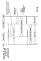
- FIG. 7 is a diagram of voice call processing in a system supporting High Rate Packet Data (HRPD) communications
- FIG. 8 is a diagram of voice call processing in a system supporting High Rate Packet Data (HRPD) communications employing a reflector;
- HRPD High Rate Packet Data
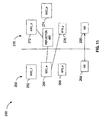
- FIG. 9 is a diagram illustrating movement of a Mobile Station (MS) within a cellular network supporting various protocols
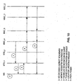
- FIG. 10 is a call flow for movement of a MS in a cellular network supporting various protocols
- FiG. 11 is a diagram illustrating movement of a Mobile Station (MS) within a cellular network supporting various protocols;
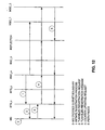
- FIG. 12 is a call flow for movement of a MS in a cellular network supporting various protocols
- FIG. 13 is a block diagram of an Access Terminal (AT);
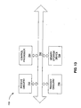
- FIG. 14 is a block diagram of an Access Network (AN) element.
- FIG. 15 is a call flow according to one embodiment.
- High Data Rate (HDR) subscriber station referred to herein as an access terminal (AT) may be mobile or stationary, and may communicate with one or more HDR base stations, referred to herein as modem pool transceivers (MPTs).
- An access terminal transmits and receives data packets through one or more modem pool transceivers to an HDR base station controller, referred to herein as a modem pool controller (MPC).
- Modem pool transceivers and modem pool controllers arc parts of a network called an access network,
- An access network transports data packets between multiple access terminals.
- the access network may be further connected to additional networks outside the access network, such as a corporate intranet or the Internet, and may transport data packets between each access terminal and such outside networks.
- An access terminal that has established an active traffic channel connection with one or more modem pool transceivers is called an active access terminal, and is said to be in a traffic state.
- An access terminal that is in the process of establishing an active traffic channel connection with one or more modem, pool transceivers is said to be in a connection setup state.
- An access terminal may be any data device that communicates through a wireless channel or through a wired channel, for example using fiber optic or coaxial cables.
- An access terminal may further be any of a number of types of devices including but not limited to PC card, compact flash, external or internal modem, or wireless or wireline phone.
- the communication link through which the access terminal sends signals to the modem pool transceiver is called a reverse link.
- the communication link through which a modem pool transceiver sends signals to an access terminal is called a forward link.
- a remote network node such as a personal or laptop computer (PC) connected to a packet-data-capable wireless mobile station (MS) may access the Internet through a wireless network in accordance with the IS-707 standard.
- MS Access Node
- MN Mobile Node
- remote station each refer to a mobile participant in a wireless communication.
- the remote network node such as a web browser may be built-in to the MS, making the PC optional.
- An MS may be any of a number of types of devices including, but not limited to PC card, personal data assistant (PDA), external or internal modem, or wireless phone or terminal.
- the MS sends data through the wireless network, where it is processed by a packet data serving node (PDSN).
- PDSN packet data serving node
- the Point toPpoint Protocol (PPP) state for a connection between an MS and the wireless network is typically maintained within the PDSN.
- the PDSN is connected to an IP network such as the Internet, and transports data between the wireless network and other entities and agents connected to the IP network. In this way, the MS can send and receive data to another entity on the IP network through the volunteers data connection.
- the target entity on the IP network is also called a correspondent node.
- FIG. 1 is a conceptual block diagram of a wireless communications system configured to support packet-switched communications.
- a remote network node 102 such as a personal or laptop computer (PC) connected to a subscriber station 104 may access a packet data network 106 through an access network 107.
- the remote network node 102 may be integrated into the subscriber station 104 such as the case might be with a web browser.
- the subscriber station 104 may be any number of devices including, but not limited to, a PC card, a personal data assistant (PDA), an external or internal modem, a wireless phone or terminal, or any other similar device.
- the packet-switched network 106 may be the Internet, a corporate intranet, or any other packet data network.
- the access network 107 may be implemented with any number of base stations dispersed throughout a geographic region.
- the geographic region may be subdivided into smaller regions known as cells with each base station serving a cell.
- a base station controller (BSC) 110 configured for packet-switched communications may be used to coordinate the activities of multiple base stations.
- a packet control function (PCF) may be integrated into the BSC 110 to control the interface with a packet data serving node (PDSN) 112.
- the PDSN 112 may be used to maintain and terminate a network connection with the remote network node 102.
- the geographic reach of the access network 107 may be extended by connecting multiple BSCs to the PDSN 112, with each BSC supporting any number of base stations.
- the wireless communications system may also be configured to support circuit-switched communications. Separate radio resources at the base station 108 may be used to connect the subscriber station 104 to a circuit-switched network 114 through an access network 115.
- the circuit-switched network 114 may be a public switched telephone network (PSTN) or the like.
- the access network 115 may be implemented with a BSC 116, which interfaces the base station 108 to a mobile switching center (MSC) 118.
- the MSC 118 provides a gateway to the circuit-switched network 114.
- the geographic reach of the access network 115 may be expanded by using the MSC 118 to interface any number of BSCs to the circuit-switched network 114, with each BSC supporting one or more base stations.
- the subscriber station 104 may be configured to monitor the circuit-switched network 114 when power is initially applied using a predetermined access procedure.
- the access procedure involves tuning the subscriber station 104 to the operating frequency assigned to circuit-switched communications, acquiring the pilot signal transmitted from that base station 108, and registering with the MSC 118 using a reverse link access channel.
- the reverse link refers to transmissions from the subscriber station 104 to the base station 108
- a forward link refers to transmissions from the base station 108 to the subscriber station 104.
- the paging channel may be used by the base station 108 to page the subscriber station 104 when a voice call arrives.
- the subscriber station 104 may send a control message to the base station 108 over the reverse link access channel indicating that it is ready to receive the call.
- the reverse link access channel may be used to send a control message to the base station 108 indicating that the subscriber station 104 is ready to place a call.
- an air link may be established between the subscriber station 104 and the base station 108 to support the call.
- air link refers to a wireless traffic channel configured to support voice and/or data communications. The pilot, paging, access and other overhead channels are always active whether or not an air link exists.
- the subscriber station 104 When the subscriber station 104 is not being used to support a voice call, it may provide a high speed network connection to the packet-switched network 106 for the remote network node 102.
- the remote network node 102 may access the packet-switched network 106 by first establishing an air link with the base station 108. This may be accomplished by tuning the subscriber station 104 to the operating frequency assigned to packet-switched communications and acquiring the pilot signal transmitted from that base station 108.
- the pilot signal for packet-switched communications is transmitted at a different carrier frequency than the pilot signal for circuit-switched communications.
- a data link may be set up between the remote network node 102 and the PDSN 112 in accordance with a point-to-point (PPP) link layer protocol.
- PPP link layer protocol may be used to negotiate an Internet Protocol (IP) address to assign to the remote network node 102.
- IP Internet Protocol
- the remote network node 102 may communicate with the packet-switched network 106 over a network connection.
- a network connection remains in tact whether or not it is being used to support communications.
- the remote network node 102 may access the packet-switched network 106 to download a web page.
- a period of inactivity over the network connection may exist after the web page is downloaded while the user reads the contents.
- the air link between the subscriber station 104 and the base station 108 may be torn down to preserve valuable wireless resources.
- the network connection that exists between the remote network node 102 and the PDSN 112 in the absence of an air link is referred to as a "dormant" connection.
- an "active" network connection may be established with a new air link between the subscriber station 104 and the base station 108 without having to renegotiate the IP address or the PPP state.
- bandwidth can be saved that would otherwise be consumed by renegotiating the IP address and PPP state, thereby reducing the latency of the network communications.
- the subscriber station 104 may be configured to retune to the operating frequency assigned to circuit-switched communications and acquire the associated forward link pilot signal. To avoid tuning back-and-forth between the two carrier frequencies when a high speed packet-switched network connection exists, the subscriber station 104 may remain tuned to the operating frequency assigned to packet-switched communications for a short period of time after the network connection becomes dormant before switching to the operating frequency assigned to circuit-switched communications. In any event, once the subscriber station 104 tunes to the operating frequency assigned to circuit-switched communications, it may then monitor the reverse link paging channel associated with such communications to avoid missing a call.
- the base station 108 may use a slotted paging procedure to support voice-switched communications.
- slotted paging mode both the subscriber station 104 and the base station 108 agree in which time slots the subscriber station 104 will be paged.
- the subscriber station 104 may then power down some of its processing resources during unassigned time slots, thus conserving battery power.
- the subscriber station 104 may also be configured to periodically tune to the operating frequency assigned to packet-switched communications, acquire the associated reverse link pilot signal, and check the paging channel when the network connection is dormant. Although this approach may support continued high speed access to the packet-switched network 106 during the entire PPP session, it also tends to reduce the standby time (i.e., the percentage of time in which the processing resources in the subscriber station 104 can be powered down). Reduced standby time places a higher demand on battery power.
- An alternative approach for supporting a dormant network connection is to tunnel the page from the packet-switched network 106 to the subscriber station 104 through the air interface for circuit-switched communications, in this example the IS-2000 air interface.
- the PCF in the BSC 110 may be used to determine whether the network connection is dormant and buffer data packets from the PDSN 112 when the air link is down or when its resources are insufficient to support the flow of packets from the PDSN 112.
- the BSC 110 connected to the packet-switched network 106 may be configured to instruct the BSC 116 connected to the circuit-switched network to page the subscriber station 104 when the PCF determines that packets have arrived from the PDSN 112 during a dormant network connection.
- a connection 120 between the BSCs may be used to implement this function.
- the BSC 116 connected to the circuit-switched network 114 may send a command to the base station 108, which in turn pages the subscriber station 104 through the IS-2000 air interface.
- the subscriber station 104 may switch back to the operating frequency assigned to packet-switched communications and acquire the associated reverse link pilot signal.
- the subscriber station 104 may send a signal back to the base station 108 on an overhead channel indicating that it is ready to receive the data packets.
- the base station 108 may then forward the signal to the BSC 110 connected to the packet-switched network 106 which activates the network connection between the subscriber station 104 and the PDSN 112.
- a similar methodology may be implemented to avoid missing voice pages when the network connection is active. More specifically, a page from the circuit-switched network 114 may be tunneled through the air interface for packet-switched communications to the subscriber station 104, in this example the IS-856 air interface. This may be accomplished by instructing the BSC 110 connected to the packet switched network 106 to page the subscriber station 104 when a voice call is received from the circuit-switched network 114. The connection 120 between the BSCs may be used to implement this function.
- the BSC 110 connected to the packet-switched network 106 may send a command to the base station 108, which in turn pages the subscriber station 104 through the air interface for packet-switched communications, in this example the IS-856 air interface.
- the subscriber station 104 may configure a filtering mechanism that allows only certain types of pages associated with circuit-switched services to be sent through the IS-856 air interface.
- the subscriber station 104 may request to receive voice pages, but not pages associated with short message services (SMS) while it is tuned to the operating frequency assigned to packet-switched communications.
- SMS short message services
- the subscriber station 104 may suspend the transmission of data packets, switch back to the operating frequency assigned to circuit-switched communications and acquire the associated reverse link pilot signal.
- the subscriber station 104 may send a signal back to the base station 108 over the access channel indicating that it is ready to receive the voice call.
- an air link may be established between the subscriber station 104 and the base station 108 to support the call.
- the various embodiments of a wireless communications system described thus far may be used to support both circuit-switched and packet-switched applications.
- the subscriber station 104 may be used to maintain a high speed network connection while supporting voice-switched communications, and maintain voice connectivity while supporting packet-switched communications. This type of operation may be maintained even as the subscriber station 104 moves across sub-network boundaries.
- the sub-network boundaries will be the same for packet-switched and circuit-switched communications with each sub-network being defined as the entire geographic region covered by a single MSC.
- those skilled in the art will appreciate that various modifications may be made to the described embodiments to accommodate sub-network boundaries that are different.
- FIG. 2 is a conceptual block diagram illustrating an example of a wireless communications system.
- a single BSC may be used to support both packet-switched and circuit-switched communications because of the common sub-network boundaries.
- the PDSN 112 may be used to establish, maintain and terminate a PPP session with the remote network node 102 during packet-switched communications.
- a serving BSC 202 a may be used to connect a serving base station 108 a to the PDSN 112 and a target BSC 202 b may be used to connect a target base station 108 b to the PDSN 112.
- the subscriber station 104 is shown in FIG. 2 moving through different subnetworks by a series of broken lines.
- the subscriber station 104 is shown initially moving through a serving region 204 a and uses the serving base station 108 a to access the packet-switched network 106.
- the subscriber station 104 may then tune to the operating frequency assigned to voice-switched communications, acquire the associated reverse link pilot signal, and monitor the reverse link paging channel for a voice call.
- the network connection may be maintained by using any number of different procedures.
- One example will be presented below.
- the subscriber station 104 As the subscriber station 104 moves toward the target region 204b, it detects changes in the pilot signal strength from both the serving and target base stations 108 a and 108 b . When the pilot signal strength from the target base station 108 b exceeds a threshold, the target base station 108 b may be added to the active set of the subscriber station 104. The active set is a list of base stations in communication with the subscriber station 104. The subscriber station 104 may then send a request through the target base station 108 b to the target BSC 202 b requesting a unique address identifier to support packet-switched communications in the target region 204 b .
- This request is commonly referred to as a "UATI Request" in the IS-856 standard.
- the request may be tunneled through the air interface for voice-switched communications between the target base station 108 b and the subscriber station 104. Included in the request is the unique address identifier of the subscriber station 104 originally assigned to it by the serving BSC 202 a to support packet-switched communications in the serving region 204 a .
- the target BSC 202 b may use this unique address identifier contained in the request to retrieve the PPP session from the serving BSC 202 a .
- the target BSC 202 b may establish a logical resource connection with the PDSN 112 and tunnel a new unique address identifier assignment to the subscriber station 104 through the air interface for voice-switched communications.
- the unique address identifier assignment is commonly referred to as a "UATI Assignment" in the IS-856 standard.
- the logical resource connection between the serving BSC 202 a and the PDSN 112 may also be released. The handoff between the serving and target BSCs 202 a and 202 b does not affect the PPP state of the remote network node 102 thereby maintaining the network connection to the PDSN 112.
- Voice connectivity may be maintained by any number of procedures.
- the subscriber station 104 will be described as initially moving through the serving region 204 a while supporting an active network connection between the remote network node 102 and the packet-switched network 106.
- the subscriber station 104 As the subscriber station 104 moves toward the target region 204 b , it detects changes in the pilot signal strength from both the serving and target base stations 108 a and 108 b . This information may be reported back to the serving BSC 202 a through the serving base station 108 a .
- the serving BSC 202 a also referred to as an anchor BSC, may be used to register the subscriber station 104 with the target MSC 118a.
- the target base station 108 b may be added to the active set of the subscriber station 104.
- the active set is generally maintained at the BSC, which in this case would be the anchor BSC 202 a .
- the anchor BSC 202 a having knowledge of the target base station 108 b covering the region in which the subscriber station 104 is about to enter, may send a message to the subscriber station 104 instructing it to register with the target MSC 118 b .
- the registration request may be the same as specified in the IS-2000 standard, or any other suitable format, and may be tunneled through the air interface for packet-switched communications between the target base station 108b and the subscriber station 104.
- the registration request may be used by the subscriber station 104 to generate a registration message.
- a random number in the registration request generated by the anchor BSC 202 a may be used to digitally sign the registration message.
- the registration message may be tunneled back through the air interface for packet-switched communications from the subscriber station 104 the target base station 108 b , and from there, routed to the anchor BSC 202 a .
- the signature may be verified, and the information in the registration message may be used to create a location update request.
- the location update request may be sent to the target MSC 118 b to complete the registration process.
- the anchor BSC 202 a may determine the appropriate MSC to send the location update request through an identifier (ID) for the target base station 108 b .
- ID identifier
- the target base station ID may be appended to the registration message at the target base station 108 b , or accessed separately by the anchor BSC 202 a through an exchange of signaling messages.
- the anchor BSC 202 a may route the location update request through a reflector 302 to the target MSC 118 b as illustrated in FIG. 3 .
- the reflector 302 may also be used to route pages from the circuit-switched network 114 between the target MSC 118 b and the anchor BSC 202 a .
- the reflector 302 may be configured to append a cellular identifier to the location update request of a virtual cell that is bound to the reflector 302. From the perspective of the target MSC 118 b , the reflector 302 appears as a BSC. Therefore, the target MSC 118 b does not need to be modified in order to maintain voice connectivity during an active network connection.
- the target BSC 202 b may be used as a reflector.
- the location update request may be routed by the anchor BSC 202 a through the target BSC 202 b to the target MSC 118 b .
- Pages from the circuit-switched network 114 may be routed by the target MSC 118 b through the target BSC 202 b to the anchor MSC 202 a for delivery to the subscriber station 104.
- FIG. 4 is a conceptual block diagram illustrating one possible configuration of the subscriber station 104.
- the precise configuration of the subscriber station 104 may vary depending on the specific application and the overall design constraints.
- the various inventive concepts will be described in the context of a CDMA subscriber station; however, such inventive concepts are likewise suitable for use in various other communication devices. Accordingly, any reference to a CDMA subscriber station is intended only to illustrate the various aspects of the present invention, with the understanding that such aspects have a wide range of applications.
- the subscriber station 104 may be implemented with a software based processor, or any other configuration known in the art.
- An example of a hardware configuration for a software based processor is shown in FIG. 4 .
- the processor has a microprocessor 402 at its core with memory 404.
- the microprocessor 402 may provide a platform to run software programs that, among other things, manage access to the circuit-switched and packet-switched networks.
- the subscriber station 104 may also include various user interfaces 406 such as a speaker, microphone, keypad, display, and the like. These user interfaces 406 are generally used to support voice and low rate data communications across the circuit switched network. In some embodiments, the user interfaces 406 may also be used to support a high speed connection to the packet-switched network, such as the case may be with an integrated web browser. In the described embodiment, a local interface 408 may be provided to support a high speed connection between the remote network node and the packet-switched network.
- a digital signal processor (DSP) 410 may be implemented with an embedded communications software layer which runs specific algorithms to reduce the processing demands on the microprocessor 402.
- the DSP 410 may be used to provide encoding and modulation of communications from either the user interfaces 406 or the local interface 408.
- the DSP 410 may also provide additional functions such as spreading the communications with the appropriate pseudo-random noise (PN) and Walsh codes, and combining the spread communications with various control and overhead channels.
- PN pseudo-random noise
- the software layer also interfaces the DSP hardware to the microprocessor 402 and may provide low level services such as allocation of resources to allow higher level software programs to run.
- the precise manner in which the communications are processed may depend on the air interface for the specific type of communication.
- the encoding and modulation scheme, as well as the way the control and overhead messages are combined may be different depending on whether the communications are destined for the voice-switched or packet-switched network.
- the communications processed by the DSP 410 may be provided to an analog circuit 412 for digital-to-analog conversion, amplification, filtering and upconversion to a carrier frequency suitable for transmission over the reverse link.
- the carrier frequency produced by the analog circuit 412 may be controlled by a tuner 414.
- the tuner 414 may be a stand-alone device as shown in FIG. 4 , or alternatively, may be integrated into the analog circuit 412.
- the microprocessor 402 may be used to set the tuner 414 in accordance with the air interface for the particular reverse link transmission.
- the air interface for circuit-switched communications may call for a different carrier frequency than the air interface for packet-switched communications.
- the analog circuit 412 may be used to amplify, filter and downconvert the transmission to a baseband signal. Analog-to-digital conversion of the baseband signal may also be provided by the analog circuit 412. Depending on whether the forward link communications originate from the voice-switched or packet-switched network, the microprocessor 402 sets the tuner 414 in accordance with the appropriate air interface to ensure that the downconversion function of the analog circuit 412 produces a baseband signal.
- the baseband signal from the analog circuit 412 may be provided to the DSP 410 which may be used to separate the control and overhead messages from the communications.
- the control and overhead messages may then be provided to the microprocessor 402.
- the DSP 410 may also provide additional signal processing functions to the communications including demodulation and decoding. In CDMA applications, the DSP 410 may also provide despreading with the appropriate PN and Walsh codes.
- the processed communications may then be provided to the microprocessor 402 which manages the delivery of the communications to the various user interfaces 406 and local interface 408.
- the microprocessor 402 may be configured to initiate the acquisition process by setting the tuner 414 to the operating frequency for circuit-switched communications.
- the microprocessor 402 may then invoke various signal processing functions including a search by the DSP 410 through an unknown region of time and frequency to acquire the forward link pilot signal.
- the DSP 410 acquires the forward link pilot signal, it may prompt the microprocessor 402 to add the base station from which the signal was transmitted to its active list.
- the subscriber station 104 may then communicate with that base station through various control, overhead and traffic channels.
- control and overhead messages are separated from the communications in the DSP 410 and provided to the microprocessor 402.
- the microprocessor 402 may be configured to monitor the control and overhead messages for a page (or any other message) from the packet-switched network tunneled through the air interface for circuit-switch communications. If a page from the packet-switched network is detected by the microprocessor 402, and the subscriber station 104 is not engaged in a voice call, then the tuner 414 may be set to the operating frequency for packet-switched communications. If, on the other hand, the subscriber station 104 is supporting a voice call, the microprocessor 402 may allow the call to be completed before switching the tuner 414.
- the microprocessor 402 may then be used to establish an air link with the base station through an exchange of signaling messages. Once the air link is established, a data link and network connection may be established between the PDSN and the remote network node connected to the local interface 408.
- the microprocessor 402 may be used to monitor the control and overhead messages for a page from the circuit-switched network tunneled through the air interface for packet-switched communications. If a page from the circuit-switched network is detected, the microprocessor 402 may be used to signal the base station to suspend the transmission of data packets while the subscriber station takes the call. The signaling to the base station may be provided to the BSC where the PCF may be used to buffer the data packets arriving from the packet-switched network.
- the microprocessor 402 may then set the tuner 414 to the operating frequency for circuit-switch communications, acquire the associated pilot signal, and establish an air link to support the voice call. Once the voice call is complete, the microprocessor 402 may switch the tuner 414 back to the operating frequency for packet-switched communications and complete the data packet transmission.
- the microprocessor 402 may also include a timer (not shown) that is triggered when the active network connection becomes dormant.
- the microprocessor 402 may be configured to hold the tuner 414 at the operating frequency for packet-switched communications while the timer is running in case the network connection becomes active again. Once the timer times out, the microprocessor 402 may be used to switch the tuner 414 to the operating frequency for circuit-switched communications, acquire the associated pilot signal, and monitor the various control and overhead channels for a voice call.
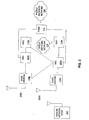
- FIG. 5 illustrates a packet data network 150 according to one embodiment.
- the packet data system 150 includes two System Identification (SID) zones 160, 170, each having multiple Network Identification (NID) zones 162, 164, 166, 172, 174, and 176.
- SID System Identification
- NID Network Identification
- the SID/NID are used in voice systems and generally identify a serving area. For example, an MSC serving area may be associated with a pair of (SID, NID) values.
- PZIDs Packet Zone Identifications
- SID 160 includes PZIDs 180, 182, and 184
- SID 170 includes PZIDs 180, 182, 184.
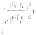
- FIG. 6 illustrates a wireless communication system 250 configured to support circuit-switched communications and packet-switched communications.
- a first portion 260 of the system includes a Mobile Switching Center (MSC) identified as MSC_1 262, coupled to a Base Station Controller (BSC) BSC_a 264 and a Base Station Transceiver (BTS) BTS_x 266 adapted for communication with a Mobile Station (MS) 268. While in the first portion 260 of the system, the MS 268 establishes a High Rate Packet Data (HRPD) communication.
- the HRPD communication may be a high data rate communication, a broadcast communication, or other packet-switched type communication.
- the system 250 also includes a second portion 270 including MSC_2 272, BSC_b 274, and BTS_y 276 adapted for communication with mobile stations within portion 270.
- Each of the portions 260 and 270 covers a geographical area.
- the MS when a MS moves into a portion, the MS registers with the corresponding MSC. For circuit-switched communications, such as a voice call, the MSC sends a page to the MS via the BSC and BTS. The MS responds by answering the page and the call is established.
- the MS 268 first registers with MSC_1 262 of portion 260. In the present scenario, the MS 268 requests a data service and thereby establishes an HRPD data service. In other words, the MS 268 establishes a packet-switched communication via portion 260. The MS 268 thereafter moves into the geographical area served by portion 270 while maintaining the HRPD data service with portion 270. The MS 268 continues to receive and/or transmit packet data via BSC_a 264. Each of portions 260, 270 may be a subnet as illustrated in FIG. 6 .
- the hybrid protocol provides a means for processing communications through both a circuit-switched network and a packet-switched network. For example, a mobile station may desire to use a data service while maintaining connectivity for voice calls.
- the hybrid protocol ensures that the MS 268 stays registered in the circuit-switched system, which in the present example is an IS-2000 system.
- the BSC_a 264 is referred to as an "anchor" BSC.
- the anchor BSC, BSC 264 registers the MS 268 with MSC_2 272 as the MS 268 enters the foot-print of MSC_2 272. Movement of the MS 268 into the geographic area or footprint served by another MSC triggers the anchor BSC to register the MS with that MSC.
- the new BTS is entered into an Active Set (AS) for communication.
- AS Active Set
- the BTS_y 276 enters into the AS of MS 268.
- the BSC_a 264 anchor base station
- the BSC_a 264 determines that the MS 268 has entered the foot-print or geographic area of MSC_2 272 by examining the sector ID (SID) of BTS_y 276.
- SID sector ID
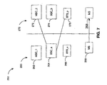
- the BSC_a 264 sends a TunneledRegistrationRequest message to the MS 268 to force the MS 268 to register with the new MSC.
- the message contains a 32-bit random number, RAND, which the MS 268 needs to generate the AUTHR.
- the MS 268 processes this message as if it has received a "Registration Request Order" such as in IS-2000, and generates a TunneledRegistrationMessage.
- the mobile When performing the registration, the mobile must use the RAND given in the TunneledRegistrationRequest message as, RANDs, specified in IS-2000.
- the content of the TunneledRegistrationMessage is identical to a Registration message of IS-2000.
- the NUM_ADD_PILOTS field is set to zero in this message.
- the BSC_a 264 uses the information given in the TunneledRegistrationMessage to construct a "Location Updating Request" (as specified in the IOS) and register the MS 268 with MSC_2 272.
- the BSC_a 264 determines to which MSC to send the "Location Updating Request" based on the MSBs of the BTS_y's SectorID and an internal mapping table or by using the bits in the SectorID of BTS_y directly.
- the communication paths are illustrated in FIG. 7 .
- FIG. 8 provides a signal flow diagram consistent therewith.
- FIGs. 9 and 10 illustrate another scenario wherein BSC_a 264 initiates a registration process with the MS 268 via BTS_x 266, wherein a tunneled registration process is provided.
- the MS 268 sends a tunneled registration message via BTS_x 266 with location updating request continuing to BSC_a 264, BSC_b 274, MSC_1 262, and MSC_2 272.
- the MSC_2 272 then provides PSDN pages to the MS 268 via BSC _b 274, BSC_a 264, and BTS_x 266.
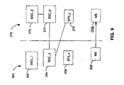
- the anchor BSC can forward the "A1: Location Updating Request" through a Reflector to the neighboring MSC as illustrated in FIGs. 11 and 12 .
- the Reflector 440 forwards the "A1 Location Updating Requests" from the anchor BSC to the MSC to which it is connected.
- the Reflector 440 forwards the "A1 Paging Requests” from the MSC to the anchor BSC.
- the Reflector 440 maintains the binding between the international mobile station (IMSI) and the associated anchor BSC.
- IMSI international mobile station
- the Reflector 440 appears as a BSC. Therefore, the A1 interface does not need to be modified in order to accommodate the cross-paging feature.
- the BSC_a 264 communicates with the Reflector 440 and not the MSC_2 272.
- the cell identifier is used to determine the BSC for delivery of pages, this may cause, for example, the MSC_2 272 to deliver the page to BSC_b 274, which is associated with BTS_y 276.
- the Reflector 440 gives the Cell ID of a virtual cell that is bound to the Reflector 440 when it registers with the MSC_2 272. In this way the MSC_2 272 delivers the pages to the Reflector 440 (and not BSC_b 274) and the Reflector 440 passes the page to BSC_a 264.
- the method copies the Radio Session for the mobile to BSC_b.
- the Radio Session includes information about the anchor BSC (i.e., BSC_a) and allows the BSC_b to forward "A1 Paging Request" to BSC_a.
- the "A1 Location updating Massage” path is from BSC_a to BSC_b to MSC_2.
- the "A1: Paging Request Message” path is MSC_2 to BSC_b to BSC_a (which will then send the page to mobile through BTS_y). This alternative requires no change in the MSC or A1 interface.
- One problem occurs when a mobile station switches to the frequency associated with a dormant packet data application and then the mobile station crosses a packet zone boundary. It is necessary to ensure the packet data application page is delivered to the mobile.
- One solution provides for the BSC to ensure that pages from the PDSN network are directed appropriately. For example, when a mobile station monitors the packet data frequency and moves across BSCs, the target BSC must ensure that the PDSN points to the right BSC at all times by retrieving the radio session from the source BSC.
- the mobile station selects a Service Option (SO), wherein crossing boundaries is specified.
- SO Service Option
- the SO ideally specifies steps to be taken when the mobile station crosses a packet zone boundary. Such steps would be similar to those specified in SO 33, i.e., the mobile station sends an origination message with an indication that the mobile station has crossed a boundary.
- the mobile station sends a UATI to the target BSC. Note this may require a specific message sent on the packet data frequency.
- the Radio Access Network sends the mobile station a page specifying SO 59 when a packet destined for the mobile station arrives on the packet-switched network.
- Push services may be served by the packet data air-interface.
- the mobile station may monitor the circuit-switched frequency exclusively.
- the mobile station may become active after being idle for a short period of time. Therefore, in order to avoid tuning back-and-forth between two air-interfaces too quickly, the mobile stays tuned to the packet data air-interface for 'T' seconds before it tunes to the circuit-switched air-interface.
- ⁇ T' will be a configurable attribute of the Hybrid Protocol.
- the target BSC will retrieve the radio session from the source BSC and establish an R-P interface with the PDSN.
- "1x:” denotes a message sent using the 1x air-interface and frequency; and "SO 59" denotes messages defined by SO 59.
- the mobile station selects SO 59, which is a service option identifying a high rate packet data service over a 1x network.
- the base station will page a mobile station and include the SO 59 identifier to notify the mobile station of a pending high data rate communication.
- FIG. 13 illustrates an Access Terminal (AT) 750 supporting one or more of the hybrid protocol methods detailed hereinabove.
- the AT 750 includes a communication bus 760 coupling receive circuitry 752, control processor 754, transmit circuitry 756, and a memory storage device 758.
- Computer-readable instructions for implementing a hybrid protocol method are stored in memory storage device 758.
- FIG. 14 illustrates an Access Network (AN) 800 supporting one or more of the hybrid protocol methods detailed hereinabove.
- AN 800 includes an antenna 814 couple to a doplever (DUP) 810, which is coupled to a transmit path and a receive path.
- the antenna 814 may represent a common antenna or may be a grouping of antennas.
- signals are routed through receiver (RCVR) 816 and demodulator (DEMOD) 818, which is coupled to control processor 804.
- Control processor 804 is further coupled to local interface 812, and memory 802.
- the control processor 804 is coupled to modulator (MOD) 806 and transmitter (TMTR) 808.
- Computer-readable instructions for implementing a hybrid protocol method are stored in memory storage device 802.
- FIG. 15 illustrates call flow according to one scenario.
- the target BSC retrieves the session information from the source BSC on a mobile station crossing a boundary.
- the PDSN establishes an interface with the target BSC.
- the interface with the source BSC is then tom down in favor of the target BSC.
- a connection is established with the target BSC and data flows to the mobile station through the target BSC.
- the embodiments described herein allow push services to be served by the AN, in a system supporting both circuit-switched and packet-switched transmissions.
- the mobile station periodically monitors the packet data network for data packet pages. Monitoring two air-interfaces periodically in the slotted mode reduces the standby time. According to one embodiment, the mobile station monitors both systems until the packet-switched network is idle for a threshold time period T. At this time, the mobile station only monitors the circuit-switched network. The service option will then identify which type of page is received, either for a circuit-switched communication or a packet-switched communication. When the mobile station receives a notification of a packet data page, the mobile station will then monitor the packet data frequency. Again, once an idle time period passes a threshold, the mobile station begins to monitor only the circuit-switched network.
- the RAN While the mobile station is monitoring the 1x air-interface only, the RAN sends the mobile a page with a specific service option, such as SO 59, on receipt of a packet destined for the mobile arrives on the packet-switched network. In this scenario, push services may be served by the packet-switched network. After switching to the circuit-switched air-interface, the mobile station may monitor the associated frequency exclusively.
- a specific service option such as SO 59
- ⁇ T' may be a configurable attribute of the Hybrid Protocol.
- While monitoring the packet data air-interface only e.g., when in the connected state or before the mobile station tunes back to the circuit-switched interface and camps there), notifications for the circuit-switched services are sent through the packet data air-interface.
- the mobile station would not necessarily be required to periodically switch between monitoring the packet data frequency and circuit-switched frequency due to the delivery of notification to the mobile station, which is received independent of the air-interface that the mobile station is currently monitoring.
- the Hybrid Protocol provides a new air-interface protocol which allows the transmission of notifications for the circuit-switched services (e.g., voice pages) through the packet data air-interface.
- Such Hybrid Protocol allows the mobile station to configure a filtering mechanism such that only certain types of pages associated with circuit-switched services are sent through the packet data air-interface. For example, the mobile may request to receive only those notifications for voice and not for Short Messaging Service (SMS) while tuned to the packet data interface.
- SMS Short Messaging Service
- DSP digital signal processor
- ASIC application specific integrated circuit
- FPGA field programmable gate array
- a general-purpose processor may be a microprocessor, but in the alternative, the processor may be any conventional processor, controller, microcontroller, or state machine.
- a processor may also be implemented as a combination of computing devices, e.g., a combination of a DSP and a microprocessor, a plurality of microprocessors, one or more microprocessors in conjunction with a DSP core, or any other such configuration.
- a software module may reside in RAM memory, flash memory, ROM memory, EPROM memory, EEPROM memory, registers, hard disk, a removable disk, a CD-ROM, or any other form of storage medium known in the art.
- a storage medium may be coupled to the processor such that the processor can read information from, and write information to, the storage medium.
- the storage medium may be integral to the processor.
- the processor and the storage medium may reside in an ASIC.
- the ASIC may reside in the subscriber station, or elsewhere.
- the processor and the storage medium may reside as discrete components in the subscriber station, or elsewhere in an access network.
Abstract
Description
- The present disclosure relates generally to wireless communications, and more specifically, to various systems and techniques for implementing a hybrid protocol supporting communications with multiple networks.
- Wireless networks are widely deployed to provide various types of wireless communication services. Numerous air interfaces have been developed over the years to support wireless communications including frequency division multiple access (FDMA), time division multiple access (TDMA), code division multiple access (CDMA), as well as many others. These interfaces have been standardized to facilitate interoperation between equipment manufactured by different companies. By way of example, voice services using COMA technology has been standardized in the United States in Telecommunications Industry Association TIA/EIA/IS-95-B, entitled "Mobile Station-Base Station Compatibility Standard for Dual-Mode Wideband Spread Spectrum Cellular Systems," and referred to herein as "IS-95." More recently, CDMA technology has been expanded to provide both voice and data services in the United States in Telecommunications Industry Association (TIA), entitled "Upper Layer (Layer 3) Signaling Standard for cdma2000 Spread Spectrum Systems, Release A -Addendum I," dated October 27, 2000, and referred to herein as "IS-2000." To satisfy the increasing demand for high speed data services, an additional standard has been proposed in TIA, entitled "cdma2000 High Rate Packet Data Air Interface Specification," and referred to herein as "IS-856."
- With the rapid expansion of communication services and the various standards that support them, it is highly desirable to develop technology that is compatible with multiple air interface standards. With this technology, a wireless communications device may be used to support voice and low speed data using IS-2000, but rely primarily on IS-856 to support high speed Internet applications. The challenge faced by designers is that each of these standards has their own unique set of protocols, services, data rates, and operating frequencies. Accordingly, there is a need in the art for an innovative approach to support wireless communication devices with multiple air interface standards. The approach should not be limited to devices supporting IS-2000 and IS-856 applications, but should be a broad based solution applicable to devices supporting various other air interface standards.
WO-A-01/10080
WO 01/31963
US 2002/0154627 describes a method for maintaining an IP session via a first radio network while being tuned to a second radio network. - Aspects of the present invention are illustrated by way of example, and not by way of limitation, in the accompanying drawings, wherein:
-
FIG. 1 is a conceptual block diagram of a wireless communications system; -
FIG. 2 is a conceptual block diagram of a wireless communication system that extends across geographic coverage regions; -
FIG. 3 is a conceptual block diagram of another embodiment of a wireless communications system that extends across geographic coverage regions; -
FIG. 4 is a conceptual block diagram of a subscriber station for use in a wireless communications system; -
FIG. 5 is a diagram illustrating movement of a mobile station and corresponding configurations in a wireless system configuration; -
FIG. 6 is a diagram of a wireless system configuration; -
FIG. 7 is a diagram of voice call processing in a system supporting High Rate Packet Data (HRPD) communications; -
FIG. 8 is a diagram of voice call processing in a system supporting High Rate Packet Data (HRPD) communications employing a reflector; -
FIG. 9 is a diagram illustrating movement of a Mobile Station (MS) within a cellular network supporting various protocols; -
FIG. 10 is a call flow for movement of a MS in a cellular network supporting various protocols; -
FiG. 11 is a diagram illustrating movement of a Mobile Station (MS) within a cellular network supporting various protocols; -
FIG. 12 is a call flow for movement of a MS in a cellular network supporting various protocols; -
FIG. 13 is a block diagram of an Access Terminal (AT); -
FIG. 14 is a block diagram of an Access Network (AN) element; and -
FIG. 15 is a call flow according to one embodiment. - . High Data Rate (HDR) subscriber station, referred to herein as an access terminal (AT), may be mobile or stationary, and may communicate with one or more HDR base stations, referred to herein as modem pool transceivers (MPTs). An access terminal transmits and receives data packets through one or more modem pool transceivers to an HDR base station controller, referred to herein as a modem pool controller (MPC). Modem pool transceivers and modem pool controllers arc parts of a network called an access network, An access network transports data packets between multiple access terminals. The access network may be further connected to additional networks outside the access network, such as a corporate intranet or the Internet, and may transport data packets between each access terminal and such outside networks. An access terminal that has established an active traffic channel connection with one or more modem pool transceivers is called an active access terminal, and is said to be in a traffic state. An access terminal that is in the process of establishing an active traffic channel connection with one or more modem, pool transceivers is said to be in a connection setup state. An access terminal may be any data device that communicates through a wireless channel or through a wired channel, for example using fiber optic or coaxial cables. An access terminal may further be any of a number of types of devices including but not limited to PC card, compact flash, external or internal modem, or wireless or wireline phone. The communication link through which the access terminal sends signals to the modem pool transceiver is called a reverse link. The communication link through which a modem pool transceiver sends signals to an access terminal is called a forward link.
- The detailed description set forth below in connection with the appended drawings is intended as a description of various embodiments of the present invention and is not intended to represent the only embodiments in which the present invention may be practiced. Each embodiment described in this disclosure is provided merely as an example or illustration of the present invention, and should not necessarily be construed as preferred or advantageous over other embodiments. The detailed description includes specific details for the purpose of providing a thorough understanding of the present invention. However, it will be apparent to those skilled in the art that the present invention may be practiced without these specific details. In some instances, well-known structures and devices are shown in block diagram form in order to avoid obscuring the concepts of the present invention. Acronyms and other descriptive terminology may be used merely for convenience and clarity and are not intended to limit the scope of the invention. In addition, for the purposes of this disclosure, the term "connected" can mean either a direct connection or, where appropriate in the context, an indirect connection, e.g., through intervening or intermediary devices or other means.
- In the following detailed description, various aspects of the present invention will be described in the context of a wireless communications device supporting both the IS-2000 and IS-856 air interface standards. While these inventive aspects may be well suited for use with this application, those skilled in the art will readily appreciate that these inventive aspects are likewise applicable for use in devices supporting various other air interface standards. Accordingly, any reference to a communication device with specific air interface standards is intended only to illustrate the inventive aspects, with the understanding that such inventive aspects have a wide range of applications. The International Telecommunications Union recently requested the submission of proposed methods for providing high rate data and high-quality speech services over wireless communication channels. A first of these proposals was issued by the Telecommunications Industry Association, entitled "The IS-2000 ITU-R RTT Candidate Submission." A second of these proposals was issued by the European Telecommunications Standards Institute (ETSI), entitled "The ETSI UMTS Terrestrial Radio Access (UTRA) ITU-R RTT Candidate Submission," also known as "wideband CDMA" and hereinafter referred to as "W-CDMA." A third proposal was submitted by U.S. TG 8/1 entitled "The UWC-136 Candidate Submission," hereinafter referred to as "EDGE." The contents of these submissions are public record and are well known in the art. IS-95 was originally optimized for transmission of variable-rate voice frames. Subsequent standards have built on the standard to support a variety of additional non-voice services including packet data services. One such set of packet data services was standardized in the United States in Telecommunications Industry Association TTA/EIA/IS-707-A, entitled "Data Service Options for Spread Spectrum Systems," hereafter referred to as "IS-707." A remote network node such as a personal or laptop computer (PC) connected to a packet-data-capable wireless mobile station (MS) may access the Internet through a wireless network in accordance with the IS-707 standard. As used throughout the following description, the terms MS, Access Node (AN), Mobile Node (MN) and remote station, each refer to a mobile participant in a wireless communication. Alternatively, the remote network node such as a web browser may be built-in to the MS, making the PC optional. An MS may be any of a number of types of devices including, but not limited to PC card, personal data assistant (PDA), external or internal modem, or wireless phone or terminal. The MS sends data through the wireless network, where it is processed by a packet data serving node (PDSN). The Point toPpoint Protocol (PPP) state for a connection between an MS and the wireless network is typically maintained within the PDSN. The PDSN is connected to an IP network such as the Internet, and transports data between the wireless network and other entities and agents connected to the IP network. In this way, the MS can send and receive data to another entity on the IP network through the tireless data connection. The target entity on the IP network is also called a correspondent node.
-
FIG. 1 is a conceptual block diagram of a wireless communications system configured to support packet-switched communications. Aremote network node 102 such as a personal or laptop computer (PC) connected to asubscriber station 104 may access apacket data network 106 through anaccess network 107. Alternatively, theremote network node 102 may be integrated into thesubscriber station 104 such as the case might be with a web browser. Thesubscriber station 104 may be any number of devices including, but not limited to, a PC card, a personal data assistant (PDA), an external or internal modem, a wireless phone or terminal, or any other similar device. The packet-switchednetwork 106 may be the Internet, a corporate intranet, or any other packet data network. - The
access network 107 may be implemented with any number of base stations dispersed throughout a geographic region. The geographic region may be subdivided into smaller regions known as cells with each base station serving a cell. For simplicity, onebase station 108 serving a singular cellular region is shown inFIG. 1 . A base station controller (BSC) 110 configured for packet-switched communications may be used to coordinate the activities of multiple base stations. A packet control function (PCF) may be integrated into theBSC 110 to control the interface with a packet data serving node (PDSN) 112. ThePDSN 112 may be used to maintain and terminate a network connection with theremote network node 102. The geographic reach of theaccess network 107 may be extended by connecting multiple BSCs to thePDSN 112, with each BSC supporting any number of base stations. - The wireless communications system may also be configured to support circuit-switched communications. Separate radio resources at the
base station 108 may be used to connect thesubscriber station 104 to a circuit-switchednetwork 114 through anaccess network 115. The circuit-switchednetwork 114 may be a public switched telephone network (PSTN) or the like. Theaccess network 115 may be implemented with aBSC 116, which interfaces thebase station 108 to a mobile switching center (MSC) 118. TheMSC 118 provides a gateway to the circuit-switchednetwork 114. The geographic reach of theaccess network 115 may be expanded by using theMSC 118 to interface any number of BSCs to the circuit-switchednetwork 114, with each BSC supporting one or more base stations. - The
subscriber station 104 may be configured to monitor the circuit-switchednetwork 114 when power is initially applied using a predetermined access procedure. The access procedure involves tuning thesubscriber station 104 to the operating frequency assigned to circuit-switched communications, acquiring the pilot signal transmitted from thatbase station 108, and registering with theMSC 118 using a reverse link access channel. The reverse link refers to transmissions from thesubscriber station 104 to thebase station 108, and a forward link refers to transmissions from thebase station 108 to thesubscriber station 104. Once thesubscriber station 104 is registered, it may monitor a forward link paging channel. The paging channel may be used by thebase station 108 to page thesubscriber station 104 when a voice call arrives. In response to the page, thesubscriber station 104 may send a control message to thebase station 108 over the reverse link access channel indicating that it is ready to receive the call. In the case where thesubscriber station 104 initiates the call, the reverse link access channel may be used to send a control message to thebase station 108 indicating that thesubscriber station 104 is ready to place a call. In any event, in response to communications over the reverse link access channel, an air link may be established between thesubscriber station 104 and thebase station 108 to support the call. As used throughout the following description, the term "air link" refers to a wireless traffic channel configured to support voice and/or data communications. The pilot, paging, access and other overhead channels are always active whether or not an air link exists. - When the
subscriber station 104 is not being used to support a voice call, it may provide a high speed network connection to the packet-switchednetwork 106 for theremote network node 102. Theremote network node 102 may access the packet-switchednetwork 106 by first establishing an air link with thebase station 108. This may be accomplished by tuning thesubscriber station 104 to the operating frequency assigned to packet-switched communications and acquiring the pilot signal transmitted from thatbase station 108. The pilot signal for packet-switched communications is transmitted at a different carrier frequency than the pilot signal for circuit-switched communications. Once the air link is established, a data link may be set up between theremote network node 102 and thePDSN 112 in accordance with a point-to-point (PPP) link layer protocol. Next, the PPP link layer protocol may be used to negotiate an Internet Protocol (IP) address to assign to theremote network node 102. Once an IP address is assigned, theremote network node 102 may communicate with the packet-switchednetwork 106 over a network connection. - In IS-856 compliant packet-switched communications, a network connection remains in tact whether or not it is being used to support communications. By way of example, the
remote network node 102 may access the packet-switchednetwork 106 to download a web page. A period of inactivity over the network connection may exist after the web page is downloaded while the user reads the contents. During such periods of inactivity, the air link between thesubscriber station 104 and thebase station 108 may be torn down to preserve valuable wireless resources. The network connection that exists between theremote network node 102 and thePDSN 112 in the absence of an air link is referred to as a "dormant" connection. When network communications are ready to resume, an "active" network connection may be established with a new air link between thesubscriber station 104 and thebase station 108 without having to renegotiate the IP address or the PPP state. By maintaining the network connection, bandwidth can be saved that would otherwise be consumed by renegotiating the IP address and PPP state, thereby reducing the latency of the network communications. - When the network connection is dormant, the
subscriber station 104 may be configured to retune to the operating frequency assigned to circuit-switched communications and acquire the associated forward link pilot signal. To avoid tuning back-and-forth between the two carrier frequencies when a high speed packet-switched network connection exists, thesubscriber station 104 may remain tuned to the operating frequency assigned to packet-switched communications for a short period of time after the network connection becomes dormant before switching to the operating frequency assigned to circuit-switched communications. In any event, once thesubscriber station 104 tunes to the operating frequency assigned to circuit-switched communications, it may then monitor the reverse link paging channel associated with such communications to avoid missing a call. - The
base station 108 may use a slotted paging procedure to support voice-switched communications. In the slotted paging mode, both thesubscriber station 104 and thebase station 108 agree in which time slots thesubscriber station 104 will be paged. Thesubscriber station 104 may then power down some of its processing resources during unassigned time slots, thus conserving battery power. - The
subscriber station 104 may also be configured to periodically tune to the operating frequency assigned to packet-switched communications, acquire the associated reverse link pilot signal, and check the paging channel when the network connection is dormant. Although this approach may support continued high speed access to the packet-switchednetwork 106 during the entire PPP session, it also tends to reduce the standby time (i.e., the percentage of time in which the processing resources in thesubscriber station 104 can be powered down). Reduced standby time places a higher demand on battery power. - An alternative approach for supporting a dormant network connection is to tunnel the page from the packet-switched
network 106 to thesubscriber station 104 through the air interface for circuit-switched communications, in this example the IS-2000 air interface. The PCF in theBSC 110 may be used to determine whether the network connection is dormant and buffer data packets from thePDSN 112 when the air link is down or when its resources are insufficient to support the flow of packets from thePDSN 112. TheBSC 110 connected to the packet-switchednetwork 106 may be configured to instruct theBSC 116 connected to the circuit-switched network to page thesubscriber station 104 when the PCF determines that packets have arrived from thePDSN 112 during a dormant network connection. Aconnection 120 between the BSCs may be used to implement this function. In response to an instruction from theBSC 110 connected to the packet-switchednetwork 106 to page thesubscriber station 104, theBSC 116 connected to the circuit-switchednetwork 114 may send a command to thebase station 108, which in turn pages thesubscriber station 104 through the IS-2000 air interface. - Once a page is received by the
subscriber station 104 indicating that data packets have arrived at the PCF, thesubscriber station 104 may switch back to the operating frequency assigned to packet-switched communications and acquire the associated reverse link pilot signal. Next, thesubscriber station 104 may send a signal back to thebase station 108 on an overhead channel indicating that it is ready to receive the data packets. Thebase station 108 may then forward the signal to theBSC 110 connected to the packet-switchednetwork 106 which activates the network connection between thesubscriber station 104 and thePDSN 112. - A similar methodology may be implemented to avoid missing voice pages when the network connection is active. More specifically, a page from the circuit-switched
network 114 may be tunneled through the air interface for packet-switched communications to thesubscriber station 104, in this example the IS-856 air interface. This may be accomplished by instructing theBSC 110 connected to the packet switchednetwork 106 to page thesubscriber station 104 when a voice call is received from the circuit-switchednetwork 114. Theconnection 120 between the BSCs may be used to implement this function. In response to an instruction to page thesubscriber station 104, theBSC 110 connected to the packet-switchednetwork 106 may send a command to thebase station 108, which in turn pages thesubscriber station 104 through the air interface for packet-switched communications, in this example the IS-856 air interface. Thesubscriber station 104 may configure a filtering mechanism that allows only certain types of pages associated with circuit-switched services to be sent through the IS-856 air interface. By way of example, thesubscriber station 104 may request to receive voice pages, but not pages associated with short message services (SMS) while it is tuned to the operating frequency assigned to packet-switched communications. - Once a page is received by the
subscriber station 104 indicating that a voice call has arrived, thesubscriber station 104 may suspend the transmission of data packets, switch back to the operating frequency assigned to circuit-switched communications and acquire the associated reverse link pilot signal. Next, thesubscriber station 104 may send a signal back to thebase station 108 over the access channel indicating that it is ready to receive the voice call. In response, an air link may be established between thesubscriber station 104 and thebase station 108 to support the call. - The various embodiments of a wireless communications system described thus far may be used to support both circuit-switched and packet-switched applications. The
subscriber station 104 may be used to maintain a high speed network connection while supporting voice-switched communications, and maintain voice connectivity while supporting packet-switched communications. This type of operation may be maintained even as thesubscriber station 104 moves across sub-network boundaries. For ease of explanation, the sub-network boundaries will be the same for packet-switched and circuit-switched communications with each sub-network being defined as the entire geographic region covered by a single MSC. However, those skilled in the art will appreciate that various modifications may be made to the described embodiments to accommodate sub-network boundaries that are different. -
FIG. 2 is a conceptual block diagram illustrating an example of a wireless communications system. A single BSC may be used to support both packet-switched and circuit-switched communications because of the common sub-network boundaries. As explained earlier, thePDSN 112 may be used to establish, maintain and terminate a PPP session with theremote network node 102 during packet-switched communications. In the embodiment shown inFIG. 2 , a servingBSC 202a may be used to connect a servingbase station 108a to thePDSN 112 and atarget BSC 202b may be used to connect atarget base station 108b to thePDSN 112. - The
subscriber station 104 is shown inFIG. 2 moving through different subnetworks by a series of broken lines. Thesubscriber station 104 is shown initially moving through a servingregion 204a and uses the servingbase station 108a to access the packet-switchednetwork 106. When the network connection becomes dormant, thesubscriber station 104 may then tune to the operating frequency assigned to voice-switched communications, acquire the associated reverse link pilot signal, and monitor the reverse link paging channel for a voice call. Whether thesubscriber station 104 is engaged in an active voice call, or is merely listening for a page from the circuit-switchednetwork 114, it may be desirable to maintain the network connection with the packet-switchednetwork 106 as thesubscriber station 104 crosses sub-network boundaries. - The network connection may be maintained by using any number of different procedures. One example will be presented below. As the
subscriber station 104 moves toward thetarget region 204b, it detects changes in the pilot signal strength from both the serving andtarget base stations target base station 108b exceeds a threshold, thetarget base station 108b may be added to the active set of thesubscriber station 104. The active set is a list of base stations in communication with thesubscriber station 104. Thesubscriber station 104 may then send a request through thetarget base station 108b to thetarget BSC 202b requesting a unique address identifier to support packet-switched communications in thetarget region 204b. This request is commonly referred to as a "UATI Request" in the IS-856 standard. The request may be tunneled through the air interface for voice-switched communications between thetarget base station 108b and thesubscriber station 104. Included in the request is the unique address identifier of thesubscriber station 104 originally assigned to it by the servingBSC 202a to support packet-switched communications in the servingregion 204a. Thetarget BSC 202b may use this unique address identifier contained in the request to retrieve the PPP session from the servingBSC 202a. Once thetarget BSC 202b successfully retrieves the PPP session, it may establish a logical resource connection with thePDSN 112 and tunnel a new unique address identifier assignment to thesubscriber station 104 through the air interface for voice-switched communications. The unique address identifier assignment is commonly referred to as a "UATI Assignment" in the IS-856 standard. The logical resource connection between the servingBSC 202a and thePDSN 112 may also be released. The handoff between the serving andtarget BSCs remote network node 102 thereby maintaining the network connection to thePDSN 112. - When the network connection is active, it may also be desirable to maintain the voice connectivity with the circuit-switched
network 114 as thesubscriber station 104 crosses sub-network boundaries. Voice connectivity may be maintained by any number of procedures. One example will be presented below. For the purposes of this example, thesubscriber station 104 will be described as initially moving through the servingregion 204a while supporting an active network connection between theremote network node 102 and the packet-switchednetwork 106. As thesubscriber station 104 moves toward thetarget region 204b, it detects changes in the pilot signal strength from both the serving andtarget base stations BSC 202a through the servingbase station 108a. In response, the servingBSC 202a, also referred to as an anchor BSC, may be used to register thesubscriber station 104 with thetarget MSC 118a. - Specifically, when the pilot signal strength from the
target base station 108b exceeds a threshold, thetarget base station 108b may be added to the active set of thesubscriber station 104. The active set is generally maintained at the BSC, which in this case would be theanchor BSC 202a. Theanchor BSC 202a, having knowledge of thetarget base station 108b covering the region in which thesubscriber station 104 is about to enter, may send a message to thesubscriber station 104 instructing it to register with thetarget MSC 118b. The registration request may be the same as specified in the IS-2000 standard, or any other suitable format, and may be tunneled through the air interface for packet-switched communications between thetarget base station 108b and thesubscriber station 104. The registration request may be used by thesubscriber station 104 to generate a registration message. A random number in the registration request generated by theanchor BSC 202a may be used to digitally sign the registration message. The registration message may be tunneled back through the air interface for packet-switched communications from thesubscriber station 104 thetarget base station 108b, and from there, routed to theanchor BSC 202a. - When the registration message is received by the
anchor BSC 202a, the signature may be verified, and the information in the registration message may be used to create a location update request. The location update request may be sent to thetarget MSC 118b to complete the registration process. Theanchor BSC 202a may determine the appropriate MSC to send the location update request through an identifier (ID) for thetarget base station 108b. The target base station ID may be appended to the registration message at thetarget base station 108b, or accessed separately by theanchor BSC 202a through an exchange of signaling messages. - If the
anchor BSC 202a cannot reach thetarget MSC 118b directly, then theanchor BSC 202a may route the location update request through areflector 302 to thetarget MSC 118b as illustrated inFIG. 3 . Thereflector 302 may also be used to route pages from the circuit-switchednetwork 114 between thetarget MSC 118b and theanchor BSC 202a. To ensure the delivery of pages from the circuit-switchednetwork 114, thereflector 302 may be configured to append a cellular identifier to the location update request of a virtual cell that is bound to thereflector 302. From the perspective of thetarget MSC 118b, thereflector 302 appears as a BSC. Therefore, thetarget MSC 118b does not need to be modified in order to maintain voice connectivity during an active network connection. - In an alternative embodiment, the
target BSC 202b may be used as a reflector. With this configuration, the location update request may be routed by theanchor BSC 202a through thetarget BSC 202b to thetarget MSC 118b. Pages from the circuit-switchednetwork 114 may be routed by thetarget MSC 118b through thetarget BSC 202b to theanchor MSC 202a for delivery to thesubscriber station 104. -
FIG. 4 is a conceptual block diagram illustrating one possible configuration of thesubscriber station 104. As those skilled in the art will appreciate, the precise configuration of thesubscriber station 104 may vary depending on the specific application and the overall design constraints. For the purposes of clarity and completeness, the various inventive concepts will be described in the context of a CDMA subscriber station; however, such inventive concepts are likewise suitable for use in various other communication devices. Accordingly, any reference to a CDMA subscriber station is intended only to illustrate the various aspects of the present invention, with the understanding that such aspects have a wide range of applications. - The
subscriber station 104 may be implemented with a software based processor, or any other configuration known in the art. An example of a hardware configuration for a software based processor is shown inFIG. 4 . The processor has amicroprocessor 402 at its core withmemory 404. Themicroprocessor 402 may provide a platform to run software programs that, among other things, manage access to the circuit-switched and packet-switched networks. - The
subscriber station 104 may also includevarious user interfaces 406 such as a speaker, microphone, keypad, display, and the like. Theseuser interfaces 406 are generally used to support voice and low rate data communications across the circuit switched network. In some embodiments, theuser interfaces 406 may also be used to support a high speed connection to the packet-switched network, such as the case may be with an integrated web browser. In the described embodiment, alocal interface 408 may be provided to support a high speed connection between the remote network node and the packet-switched network. - A digital signal processor (DSP) 410 may be implemented with an embedded communications software layer which runs specific algorithms to reduce the processing demands on the
microprocessor 402. By way of example, during reverse link communications, theDSP 410 may be used to provide encoding and modulation of communications from either theuser interfaces 406 or thelocal interface 408. In CDMA applications, theDSP 410 may also provide additional functions such as spreading the communications with the appropriate pseudo-random noise (PN) and Walsh codes, and combining the spread communications with various control and overhead channels. The software layer also interfaces the DSP hardware to themicroprocessor 402 and may provide low level services such as allocation of resources to allow higher level software programs to run. - The precise manner in which the communications are processed may depend on the air interface for the specific type of communication. By way of example, the encoding and modulation scheme, as well as the way the control and overhead messages are combined may be different depending on whether the communications are destined for the voice-switched or packet-switched network. In any event, the communications processed by the
DSP 410 may be provided to ananalog circuit 412 for digital-to-analog conversion, amplification, filtering and upconversion to a carrier frequency suitable for transmission over the reverse link. - The carrier frequency produced by the
analog circuit 412 may be controlled by atuner 414. Thetuner 414 may be a stand-alone device as shown inFIG. 4 , or alternatively, may be integrated into theanalog circuit 412. Themicroprocessor 402 may be used to set thetuner 414 in accordance with the air interface for the particular reverse link transmission. By way of example, the air interface for circuit-switched communications may call for a different carrier frequency than the air interface for packet-switched communications. - In the forward direction, the
analog circuit 412 may be used to amplify, filter and downconvert the transmission to a baseband signal. Analog-to-digital conversion of the baseband signal may also be provided by theanalog circuit 412. Depending on whether the forward link communications originate from the voice-switched or packet-switched network, themicroprocessor 402 sets thetuner 414 in accordance with the appropriate air interface to ensure that the downconversion function of theanalog circuit 412 produces a baseband signal. - The baseband signal from the
analog circuit 412 may be provided to theDSP 410 which may be used to separate the control and overhead messages from the communications. The control and overhead messages may then be provided to themicroprocessor 402. TheDSP 410 may also provide additional signal processing functions to the communications including demodulation and decoding. In CDMA applications, theDSP 410 may also provide despreading with the appropriate PN and Walsh codes. The processed communications may then be provided to themicroprocessor 402 which manages the delivery of the communications to thevarious user interfaces 406 andlocal interface 408. - When power is initially applied to the
subscriber station 104, it may attempt to acquire a forward link pilot signal in accordance with the air interface for circuit-switched communications. Themicroprocessor 402 may be configured to initiate the acquisition process by setting thetuner 414 to the operating frequency for circuit-switched communications. Themicroprocessor 402 may then invoke various signal processing functions including a search by theDSP 410 through an unknown region of time and frequency to acquire the forward link pilot signal. Once theDSP 410 acquires the forward link pilot signal, it may prompt themicroprocessor 402 to add the base station from which the signal was transmitted to its active list. Thesubscriber station 104 may then communicate with that base station through various control, overhead and traffic channels. - As discussed earlier, the control and overhead messages are separated from the communications in the
DSP 410 and provided to themicroprocessor 402. Themicroprocessor 402 may be configured to monitor the control and overhead messages for a page (or any other message) from the packet-switched network tunneled through the air interface for circuit-switch communications. If a page from the packet-switched network is detected by themicroprocessor 402, and thesubscriber station 104 is not engaged in a voice call, then thetuner 414 may be set to the operating frequency for packet-switched communications. If, on the other hand, thesubscriber station 104 is supporting a voice call, themicroprocessor 402 may allow the call to be completed before switching thetuner 414. Either way, themicroprocessor 402 may then be used to establish an air link with the base station through an exchange of signaling messages. Once the air link is established, a data link and network connection may be established between the PDSN and the remote network node connected to thelocal interface 408. - During an active network connection, the
microprocessor 402 may be used to monitor the control and overhead messages for a page from the circuit-switched network tunneled through the air interface for packet-switched communications. If a page from the circuit-switched network is detected, themicroprocessor 402 may be used to signal the base station to suspend the transmission of data packets while the subscriber station takes the call. The signaling to the base station may be provided to the BSC where the PCF may be used to buffer the data packets arriving from the packet-switched network. Once themicroprocessor 402 receives an indication from the base station that the transmission of data packets has been suspended, themicroprocessor 402 may then set thetuner 414 to the operating frequency for circuit-switch communications, acquire the associated pilot signal, and establish an air link to support the voice call. Once the voice call is complete, themicroprocessor 402 may switch thetuner 414 back to the operating frequency for packet-switched communications and complete the data packet transmission. - The
microprocessor 402 may also include a timer (not shown) that is triggered when the active network connection becomes dormant. In this embodiment, themicroprocessor 402 may be configured to hold thetuner 414 at the operating frequency for packet-switched communications while the timer is running in case the network connection becomes active again. Once the timer times out, themicroprocessor 402 may be used to switch thetuner 414 to the operating frequency for circuit-switched communications, acquire the associated pilot signal, and monitor the various control and overhead channels for a voice call. -
FIG. 5 illustrates apacket data network 150 according to one embodiment. Note that alternate embodiments may have different terminology for similar functional units, and may incorporate different configurations of components and functional units. For the present discussion, thenetwork 150 ofFIG. 5 , and other detailed figures, will be used for defining a path; however, alternate embodiments may define a path according to the specific configuration and functions used therein. Thepacket data system 150 includes two System Identification (SID)zones zones SIDs SID 160 includesPZIDs SID 170 includesPZIDs -
FIG. 6 illustrates awireless communication system 250 configured to support circuit-switched communications and packet-switched communications. Afirst portion 260 of the system includes a Mobile Switching Center (MSC) identified asMSC_1 262, coupled to a Base Station Controller (BSC)BSC_a 264 and a Base Station Transceiver (BTS)BTS_x 266 adapted for communication with a Mobile Station (MS) 268. While in thefirst portion 260 of the system, theMS 268 establishes a High Rate Packet Data (HRPD) communication. The HRPD communication may be a high data rate communication, a broadcast communication, or other packet-switched type communication. - The
system 250 also includes asecond portion 270 includingMSC_2 272,BSC_b 274, andBTS_y 276 adapted for communication with mobile stations withinportion 270. Each of theportions - As in
FIG. 6 , when a MS moves into a portion, the MS registers with the corresponding MSC. For circuit-switched communications, such as a voice call, the MSC sends a page to the MS via the BSC and BTS. The MS responds by answering the page and the call is established. As illustrated inFIG. 6 , theMS 268 first registers withMSC_1 262 ofportion 260. In the present scenario, theMS 268 requests a data service and thereby establishes an HRPD data service. In other words, theMS 268 establishes a packet-switched communication viaportion 260. TheMS 268 thereafter moves into the geographical area served byportion 270 while maintaining the HRPD data service withportion 270. TheMS 268 continues to receive and/or transmit packet data viaBSC_a 264. Each ofportions FIG. 6 . - As the
MS 268 is currently registered withMSC_1 262, new voice calls designated forMS 268 are processed viaMSC_1 262. A problem exists when theMS 268 is located within the geographic area ofportion 270, but receives a page for a voice call viaportion 260. TheMS 268 will respond to MSC_2 272, which does not have a context, i.e., registration information, ofMS 268. To avoid this and other problems associated with the movement of the MS within a system supporting both circuit-switched and packet-switched communications, a hybrid protocol is presented. The hybrid protocol provides a means for processing communications through both a circuit-switched network and a packet-switched network. For example, a mobile station may desire to use a data service while maintaining connectivity for voice calls. - The hybrid protocol ensures that the
MS 268 stays registered in the circuit-switched system, which in the present example is an IS-2000 system. According to the hybrid protocol, theBSC_a 264 is referred to as an "anchor" BSC. The anchor BSC,BSC 264, registers theMS 268 withMSC_2 272 as theMS 268 enters the foot-print ofMSC_2 272. Movement of theMS 268 into the geographic area or footprint served by another MSC triggers the anchor BSC to register the MS with that MSC. - Referring to
FIGs. 7 and8 , specifically, when theMS 268 crosses a subnet boundary, the new BTS is entered into an Active Set (AS) for communication. For example, asMS 268 moves intoportion 270, theBTS_y 276 enters into the AS ofMS 268. The BSC_a 264 (anchor base station) initiates the registration process forMS 268 to register withMSC_2 272. TheBSC_a 264 determines that theMS 268 has entered the foot-print or geographic area ofMSC_2 272 by examining the sector ID (SID) ofBTS_y 276. Note that to receive a notification from theMS 268 when theMS 268 moves to she foot-print of another MSC, the MSC boundaries are HRPD subnet boundaries. - The
BSC_a 264 sends a TunneledRegistrationRequest message to theMS 268 to force theMS 268 to register with the new MSC. In one embodiment, the message contains a 32-bit random number, RAND, which theMS 268 needs to generate the AUTHR. - The
MS 268 processes this message as if it has received a "Registration Request Order" such as in IS-2000, and generates a TunneledRegistrationMessage. When performing the registration, the mobile must use the RAND given in the TunneledRegistrationRequest message as, RANDs, specified in IS-2000. The content of the TunneledRegistrationMessage is identical to a Registration message of IS-2000. The NUM_ADD_PILOTS field is set to zero in this message. - The
BSC_a 264 uses the information given in the TunneledRegistrationMessage to construct a "Location Updating Request" (as specified in the IOS) and register theMS 268 withMSC_2 272. TheBSC_a 264 determines to which MSC to send the "Location Updating Request" based on the MSBs of the BTS_y's SectorID and an internal mapping table or by using the bits in the SectorID of BTS_y directly. The communication paths are illustrated inFIG. 7 . - After the registration is performed, the PSTN pages will be delivered from
MSC_2 272,BSC_a 264, and then to theMS 268 on the HRPD FTC. The mobile then tunes to the circuit-switched frequency, such as IS-2000, and responds to the page.FIG. 8 provides a signal flow diagram consistent therewith. -
FIGs. 9 and10 illustrate another scenario whereinBSC_a 264 initiates a registration process with theMS 268 viaBTS_x 266, wherein a tunneled registration process is provided. TheMS 268 sends a tunneled registration message viaBTS_x 266 with location updating request continuing toBSC_a 264,BSC_b 274,MSC_1 262, andMSC_2 272. TheMSC_2 272 then provides PSDN pages to theMS 268 viaBSC _b 274,BSC_a 264, andBTS_x 266. - If the anchor BSC cannot reach the neighboring MSC directly, then the anchor BSC can forward the "A1: Location Updating Request" through a Reflector to the neighboring MSC as illustrated in
FIGs. 11 and12 . - The
Reflector 440 forwards the "A1 Location Updating Requests" from the anchor BSC to the MSC to which it is connected. TheReflector 440 forwards the "A1 Paging Requests" from the MSC to the anchor BSC. TheReflector 440 maintains the binding between the international mobile station (IMSI) and the associated anchor BSC. - From the perspective of the MSC, the
Reflector 440 appears as a BSC. Therefore, the A1 interface does not need to be modified in order to accommodate the cross-paging feature. In this scenario, theBSC_a 264 communicates with theReflector 440 and not theMSC_2 272. - If the cell identifier is used to determine the BSC for delivery of pages, this may cause, for example, the
MSC_2 272 to deliver the page toBSC_b 274, which is associated withBTS_y 276. In order to avoid such a problem, theReflector 440 gives the Cell ID of a virtual cell that is bound to theReflector 440 when it registers with theMSC_2 272. In this way theMSC_2 272 delivers the pages to the Reflector 440 (and not BSC_b 274) and theReflector 440 passes the page toBSC_a 264. - According to another embodiment, the method copies the Radio Session for the mobile to BSC_b. The Radio Session includes information about the anchor BSC (i.e., BSC_a) and allows the BSC_b to forward "A1 Paging Request" to BSC_a. The "A1 Location updating Massage" path is from BSC_a to BSC_b to MSC_2. The "A1: Paging Request Message" path is MSC_2 to BSC_b to BSC_a (which will then send the page to mobile through BTS_y). This alternative requires no change in the MSC or A1 interface.
- One problem occurs when a mobile station switches to the frequency associated with a dormant packet data application and then the mobile station crosses a packet zone boundary. It is necessary to ensure the packet data application page is delivered to the mobile. One solution provides for the BSC to ensure that pages from the PDSN network are directed appropriately. For example, when a mobile station monitors the packet data frequency and moves across BSCs, the target BSC must ensure that the PDSN points to the right BSC at all times by retrieving the radio session from the source BSC.
- The mobile station selects a Service Option (SO), wherein crossing boundaries is specified. For example, in a 1xEVDO type system, the SO ideally specifies steps to be taken when the mobile station crosses a packet zone boundary. Such steps would be similar to those specified in SO 33, i.e., the mobile station sends an origination message with an indication that the mobile station has crossed a boundary. The mobile station sends a UATI to the target BSC. Note this may require a specific message sent on the packet data frequency.
- According to one embodiment, while the mobile station is monitoring only the circuit-switched air-interface, the Radio Access Network (RAN) sends the mobile station a page specifying SO 59 when a packet destined for the mobile station arrives on the packet-switched network. Push services may be served by the packet data air-interface. After switching to the circuit-switched air-interface, the mobile station may monitor the circuit-switched frequency exclusively.
- Due to the nature of the packet-switched services, the mobile station may become active after being idle for a short period of time. Therefore, in order to avoid tuning back-and-forth between two air-interfaces too quickly, the mobile stays tuned to the packet data air-interface for 'T' seconds before it tunes to the circuit-switched air-interface. `T' will be a configurable attribute of the Hybrid Protocol.
- From the network side, the target BSC will retrieve the radio session from the source BSC and establish an R-P interface with the PDSN. As presented in one embodiment, "1x:" denotes a message sent using the 1x air-interface and frequency; and "SO 59" denotes messages defined by
SO 59. In this embodiment, the mobile station selects SO 59, which is a service option identifying a high rate packet data service over a 1x network. The base station will page a mobile station and include theSO 59 identifier to notify the mobile station of a pending high data rate communication. -
FIG. 13 illustrates an Access Terminal (AT) 750 supporting one or more of the hybrid protocol methods detailed hereinabove. TheAT 750 includes acommunication bus 760 coupling receivecircuitry 752,control processor 754, transmitcircuitry 756, and amemory storage device 758. Computer-readable instructions for implementing a hybrid protocol method are stored inmemory storage device 758. -
FIG. 14 illustrates an Access Network (AN) 800 supporting one or more of the hybrid protocol methods detailed hereinabove. AN 800 includes anantenna 814 couple to a doplever (DUP) 810, which is coupled to a transmit path and a receive path. Theantenna 814 may represent a common antenna or may be a grouping of antennas. In the receive path, signals are routed through receiver (RCVR) 816 and demodulator (DEMOD) 818, which is coupled to controlprocessor 804.Control processor 804 is further coupled tolocal interface 812, andmemory 802. On the transmit path, thecontrol processor 804 is coupled to modulator (MOD) 806 and transmitter (TMTR) 808. Computer-readable instructions for implementing a hybrid protocol method are stored inmemory storage device 802. -
FIG. 15 illustrates call flow according to one scenario. In this scenario, the target BSC retrieves the session information from the source BSC on a mobile station crossing a boundary. The PDSN establishes an interface with the target BSC. The interface with the source BSC is then tom down in favor of the target BSC. When a data packet page arrives for the mobile station, a connection is established with the target BSC and data flows to the mobile station through the target BSC. - The embodiments described herein allow push services to be served by the AN, in a system supporting both circuit-switched and packet-switched transmissions. The mobile station periodically monitors the packet data network for data packet pages. Monitoring two air-interfaces periodically in the slotted mode reduces the standby time. According to one embodiment, the mobile station monitors both systems until the packet-switched network is idle for a threshold time period T. At this time, the mobile station only monitors the circuit-switched network. The service option will then identify which type of page is received, either for a circuit-switched communication or a packet-switched communication. When the mobile station receives a notification of a packet data page, the mobile station will then monitor the packet data frequency. Again, once an idle time period passes a threshold, the mobile station begins to monitor only the circuit-switched network.
- While the mobile station is monitoring the 1x air-interface only, the RAN sends the mobile a page with a specific service option, such as
SO 59, on receipt of a packet destined for the mobile arrives on the packet-switched network. In this scenario, push services may be served by the packet-switched network. After switching to the circuit-switched air-interface, the mobile station may monitor the associated frequency exclusively. - Due to the nature of the packet-switched services, it is likely that the mobile station will become active after being idle for a short period of time. Therefore, in order to avoid tuning back-and-forth between two air-interfaces too quickly, the mobile station stays tuned to the packet data air-interface for 'T' seconds before it tunes to the circuit-switched air-interface. `T' may be a configurable attribute of the Hybrid Protocol.
- While monitoring the packet data air-interface only (e.g., when in the connected state or before the mobile station tunes back to the circuit-switched interface and camps there), notifications for the circuit-switched services are sent through the packet data air-interface.
- The mobile station would not necessarily be required to periodically switch between monitoring the packet data frequency and circuit-switched frequency due to the delivery of notification to the mobile station, which is received independent of the air-interface that the mobile station is currently monitoring.
- The Hybrid Protocol according to one embodiment provides a new air-interface protocol which allows the transmission of notifications for the circuit-switched services (e.g., voice pages) through the packet data air-interface. Such Hybrid Protocol allows the mobile station to configure a filtering mechanism such that only certain types of pages associated with circuit-switched services are sent through the packet data air-interface. For example, the mobile may request to receive only those notifications for voice and not for Short Messaging Service (SMS) while tuned to the packet data interface.
- The various illustrative logical blocks, modules, and circuits described in connection with the embodiments disclosed herein may be implemented or performed with a general purpose processor, a digital signal processor (DSP), an application specific integrated circuit (ASIC), a field programmable gate array (FPGA) or other programmable logic device, discrete gate or transistor logic, discrete hardware components, or any combination thereof designed to perform the functions described herein. A general-purpose processor may be a microprocessor, but in the alternative, the processor may be any conventional processor, controller, microcontroller, or state machine. A processor may also be implemented as a combination of computing devices, e.g., a combination of a DSP and a microprocessor, a plurality of microprocessors, one or more microprocessors in conjunction with a DSP core, or any other such configuration.
- The methods or algorithms described in connection with the embodiments disclosed herein , or steps thereof, be embodied directly in hardware, in a software module executed by a processor, or in a combination of the two. A software module may reside in RAM memory, flash memory, ROM memory, EPROM memory, EEPROM memory, registers, hard disk, a removable disk, a CD-ROM, or any other form of storage medium known in the art. A storage medium may be coupled to the processor such that the processor can read information from, and write information to, the storage medium. In the alternative, the storage medium may be integral to the processor. The processor and the storage medium may reside in an ASIC. The ASIC may reside in the subscriber station, or elsewhere. In the alternative, the processor and the storage medium may reside as discrete components in the subscriber station, or elsewhere in an access network.
- Those of skill in the art would understand that information and signals may be represented using any of a variety of different technologies and techniques. For example, data, instructions, commands, information, signals, bits, symbols, and chips that may be referenced throughout the above description may be represented by voltages, currents, electromagnetic waves, magnetic fields or particles, optical fields or particles, or any combination thereof.
- Those of skill would further appreciate that the various illustrative logical blacks, modules, circuits, and algorithm steps described in connection with the embodiments disclosed herein may be implemented as electronic hardware, computer software, or combinations of both. To clearly illustrate this interchangeability of hardware and software, various illustrative components, blocks, module, circuits, and steps have been describes above generally in terms of their functionality. Whether such functionality is implemented as hardware or software depends upon the particular application and design constraints imposed on the overall system. Skilled artisans may implement the described functionality in varying ways for each particular application, but such implementation decisions should not be interpreted as causing a departure from the scope of the present invention.
- The previous description of the disclosed embodiments is provided to enable any person skilled in the art to make or use the present invention. Various modifications to these embodiments will be readily apparent to those skilled in the art, and the generic principles defined herein may be applied to other embodiments without departing from the scope of the invention. Thus, the present invention is not intended to be limited to the embodiments shown herein but is to be accorded the widest scope as defined by the claims.
Claims (21)
- A method of wireless communications in a system comprising a first, circuit-switched network (114) associated with a first air interface and a second, packet-switched network (106) associated with a second air interface different from the first air interface, the method comprising:monitoring the first network (114) in accordance with the first air interface;maintaining a dormant connection with the second network (106) while monitoring the first network (114), wherein the second network (106) comprises first and second geographic regions;receiving a message from the second network (106) through the first air interface, the message comprising a page from the second network; andcommunicating with the second network (106) in response to the page in accordance with the second air interface;characterised by:detecting movement into the second geographic region from the first geographic region while monitoring the first network (114); andsending a request for an identifier to an access network (118b, 202b) in the second geographic region to support communications with the second network (106), the request being sent through the first air interface.
- The method of claim 1, wherein the first network (114) comprises first and second geographic regions, the method further comprising:moving into the second geographic region from the first geographic region while monitoring the second network (106); andsending a registration request to an access network (118b, 202b) in the second geographic region to support communications with the first network (114), the registration request being sent through the second air interface.
- The method of claim 1, comprising:monitoring the second network (106) in accordance with the second air interface;detecting that the connection with the second network (106) is idle for a predetermined period of time; andmonitoring again the first network (114) in accordance with the first air interface.
- The method of claim 1, further comprising receiving a message from the first network (114) when communicating with the second network (106), the message from the first network (114) being sent through the second air interface.
- The method of claim 4, wherein the message from the first network (114) comprises a page, the method further comprising:terminating communications with the second network (106) in response to the page from the first network (114); andcommunicating with the first network (114) in accordance with the first air interface in response to the page from the first network (114).
- The method of any preceding claim, wherein the first air interface format comprises a first carrier frequency and the second air interface format comprises a second carrier frequency different from the first carrier frequency.
- A wireless communications device (104,750), comprising:means (402 to 414,752,754) for recovering information from a signal received in accordance with a first air interface, the first air interface format being associated with a first, circuit-switched network (114),means (402 to 414,752.754) for detecting from the recovered information a message from a second, packet-switched network (106), the second network (105) being associated with a second air interface format different from the first air interface;wherein the message comprises a page from the second network (106), and the wireless communications device (104,750) further comprises means (402 to 414,752 to 760) for communicating with the second network (106) in response to the page in accordance with the second air interface, andwherein a dormant connection is maintained with the second network (106) while the first network (104) is being montrored, andwherein the second network (106) comprises first and second geographinc regions;characterized by:means for detecting movement of the wireless communications device (104,750) into the second geographic region from the first geographic region while the device configured to recover information from the signal received in accordance with the first air interface; andmeans for requesting an identifier from an access network (118b,202b) in the second geographic region to support communication with the second network (106), the identifier request being sent through the first air interface.
- The wireless communications device (104,750) of claim 7, further comprising means (402 to 414,752,754) for receiving a message from the first network (114) when communicating with the second network (105), the message being sent through the first air interface.
- The wireless communications device (104,750) of claim 8, wherein the message from the first network (114) comprises a page, the wireless communications device (104,750) further comprisisng:means for terminating communication with the second network (106) in response to the page from the first network (114); andmeans (402 to 414,752 to 760) for further communicating with the first network (114) in accordance with the first air interface in response to the page from the first network (114).
- The wireless communications device (104,750) in accordance with any one of claims 7 to 9, wherein:the means (402 to 414,752,754) for recovering comprises an analog circuit (412); andthe means (402 to 414,752,754) for detecting comprises a processor (402,754).
- The wireless communications device (104,750) of claim 10, wherein the processor (402,754) is further configured to maintain a dormant connection with the second network (106) while the analog circuit (412) is configured to recover the information from the signal received in accordance with the first air interface.
- The wireless communications device (104,750) of claim 10, wherein:the first network (114) comprises first and second geographic regions; andthe processor (402,754) is further configured to:detect movement of the wireless communications device (104,750) into the second geographic region from the first geographic region while the analog circuit (412) is configured to recover information from the signal received in accordance with the second air interface; andsend a registration request to an access network (118b,202b) in the second geographic region to support communications with the first network (114), the registration request being sent through the second air interface.
- The wireless communications device (104,150) of claim 10, wherein the processor (402,754) is further configured to detect from the information recovered from the second signal a message from the first network (114).
- The wireless communications device (104,750) of claim 13, wherein the message from the first network (114) comprises a page, and wherein the analog circuit (412) is further configured to recover further information from the signal received in accordance with the first air interface in response to the page from the first network (114).
- The wireless communications device (104,750) of claim 7, further comprising:means (752,754,402 to 414) for monitoring the second network (106) in accordance withe the second air interface;means (402,754) for detecting that the connection with the second network (106) is idle for a predetermined period of time: andmeans (752,754,402 to 414) tor monitoring the first network (114) in accordance withe the first air interface in response to the means (402,754) for detecting that the connection with the second network (106) has been idle for the predetermined period of time.
- The wireless communications device (104,750) of any one of claims 7 to 15, wherein the first air interface format comprises a first carrier frequency and the second air interface format comprises a second carrier frequency different from the first carrier frequency.
- A method of communications in a system comprising a first, circuit-switched network (114) associated with a first air interface and a second, packet-switched network (106) associated with a second air interface different from the first air interface, comprising:transmitting a signal from the first network (114) over the air from an access network (115) to a subscriber station (104) in accordance with the first air interface;transmitting a message from the second network (106) over the air from the access network (115) to the subscriber station (104) through the first air interface, the message comprising a page from the second network (106);wherein the transmission of the message comprises routing the message from the second network (106) to a second access network (107), and from the second access network (107) to the access network (115); and transmitting a second signal from the second network (106) over the air from the second access network (107) to the subscriber station (104) in accordance with the second air interface following the page, the subscriber station (104) maintaining a dormant connection with the packet-switched network (106); andcharacterised in that:the step of transmitting the signal comprises transmitting the signal from the first network(114) through a first base station controller (202a) to the subscriber station (104) in accordance with the first air interface while the subscriber station (104) moves from a first geographic region to a second geographic region; and in that the method further comprises:receiving from the subscriber station (104) by a second base station controller (202b) a request for an identifier to support communications with the second network (106) after the subscriber station (104) moves into the second geographic region, the request being sent through the first air interface, the second network (106) being associated with the second air interface; andretrieving information by the second base station controller (202b). from the first base station controller (202a) to support the communications with the second network (106).
- The method of claim 17, wherein the subscriber station (104) maintains a dormant connection with the packet-switched network (106) as it moves from the first geographic region to the second geographic region, and wherein the information retrieved by the second base station controller (202b) from the first base station controller (202a) relates to maintaining the dormant connection with the packet-switched network (106) through the second base station controller (202b) while the subscriber station (104) is receiving the signal from the circuit-switched network (114) in the second geographic region.
- The method of claim 17, wherein:the step of transmitting the signal comprises transmitting the signal from the packet-switched network (106) through a base station controller (202a) to the subscriber station (104) in accordance with the first air interface while the subscriber station (104) moves from a first geographic region to a second geographic region, the base station controller (202a) being located in the first geographic region;the method further comprising:transmitting a registration request from the subscriber station (104) to the base station controller (202a) to support communications with the circuit-switched network (114) after the subscriber station (104) moves into the second geographic region; andregistering the subscriber station (104) with a mobile switching center (118b) located in the second geographic region, the registration being performed by the base station controller (202a).
- The method of claim 19, wherein the registration of the subscriber station (104) further comprises signaling from the base station controller (202a) through a reflector (302) to the mobile switching center (118b).
- A network apparatus of a communications system comprising a first, circuit-switched network (114) associated with a first air interface and a second, packet-switched network (106) associated with a second air interface different from the first air interface, the interface, the apparatus comprising:a first access network (115) for transmitting a first signal from the first network (114) over the air to a subscriber station (104) in accordance with the first air interface and for transmitting a message from the second network (106) over the air to the subscriber station (104) through the first air interface, the message comprising a page from the second network (106):means for routing the message from the second network (106) to a second access network (107), and from the second access network (107) to the first access network (115), anda second access network (107) for transmitting a second signal from the second network (106) over the air to the subscriber station (104) in accordance with the second air interface following the page, the subscriber station (104) maintaining a dormant connection with the packet-switched network (106);characterised in that:the first access network (115) comprises a first base station controller (202a) for transmitting the first signal from the first network (114) to the subscriber station (104) in accordance with the first air interface while the subscriber station (104) moves from a first geographic region to a second geographic region; and in that the network apparatus further comprises:a second base station controller (202b) for receiving from the subscriber station (104) a request for an identifier to support communications with the second network (106) after the subscriber station (104) moves into the second geographic region, the request being received through the first air interface, the second network (106) being associated with the second air interface; andmeans for retrieving information by the second base station controller (202b) from the first base station controller (202a) to support the communications with the second network (106).
Priority Applications (2)
| Application Number | Priority Date | Filing Date | Title |
|---|---|---|---|
| EP10175359.8A EP2259642B1 (en) | 2002-12-18 | 2003-12-17 | Hybrid protocol to support communications with multiple networks |
| EP10175363A EP2252020A1 (en) | 2002-12-18 | 2003-12-17 | Hybrid protocol to support communications with multiple networks |
Applications Claiming Priority (7)
| Application Number | Priority Date | Filing Date | Title |
|---|---|---|---|
| US692907 | 1996-07-31 | ||
| US43477202P | 2002-12-18 | 2002-12-18 | |
| US434772P | 2002-12-18 | ||
| US45438503P | 2003-03-12 | 2003-03-12 | |
| US454385P | 2003-03-12 | ||
| US10/692,907 US7916715B2 (en) | 2002-12-18 | 2003-10-23 | Hybrid protocol to support communications with multiple networks |
| PCT/US2003/040414 WO2004057815A2 (en) | 2002-12-18 | 2003-12-17 | Hybrid protocol to support communications with multiple networks |
Related Child Applications (3)
| Application Number | Title | Priority Date | Filing Date |
|---|---|---|---|
| EP10175359.8A Division EP2259642B1 (en) | 2002-12-18 | 2003-12-17 | Hybrid protocol to support communications with multiple networks |
| EP10175363.0 Division-Into | 2010-09-06 | ||
| EP10175359.8 Division-Into | 2010-09-06 |
Publications (2)
| Publication Number | Publication Date |
|---|---|
| EP1590928A2 EP1590928A2 (en) | 2005-11-02 |
| EP1590928B1 true EP1590928B1 (en) | 2011-08-24 |
Family
ID=32600920
Family Applications (3)
| Application Number | Title | Priority Date | Filing Date |
|---|---|---|---|
| EP10175363A Withdrawn EP2252020A1 (en) | 2002-12-18 | 2003-12-17 | Hybrid protocol to support communications with multiple networks |
| EP03813754A Expired - Lifetime EP1590928B1 (en) | 2002-12-18 | 2003-12-17 | Hybrid protocol to support communications with multiple networks |
| EP10175359.8A Expired - Lifetime EP2259642B1 (en) | 2002-12-18 | 2003-12-17 | Hybrid protocol to support communications with multiple networks |
Family Applications Before (1)
| Application Number | Title | Priority Date | Filing Date |
|---|---|---|---|
| EP10175363A Withdrawn EP2252020A1 (en) | 2002-12-18 | 2003-12-17 | Hybrid protocol to support communications with multiple networks |
Family Applications After (1)
| Application Number | Title | Priority Date | Filing Date |
|---|---|---|---|
| EP10175359.8A Expired - Lifetime EP2259642B1 (en) | 2002-12-18 | 2003-12-17 | Hybrid protocol to support communications with multiple networks |
Country Status (16)
| Country | Link |
|---|---|
| US (1) | US7916715B2 (en) |
| EP (3) | EP2252020A1 (en) |
| JP (4) | JP2006512867A (en) |
| KR (2) | KR101154384B1 (en) |
| CN (2) | CN103024902B (en) |
| AT (1) | ATE522116T1 (en) |
| AU (2) | AU2003301075A1 (en) |
| BR (1) | BR0317509A (en) |
| CA (1) | CA2510505C (en) |
| ES (1) | ES2526520T3 (en) |
| IL (1) | IL169180A0 (en) |
| MX (1) | MXPA05006674A (en) |
| NO (1) | NO20053502L (en) |
| RU (1) | RU2416879C2 (en) |
| TW (3) | TWI345900B (en) |
| WO (1) | WO2004057815A2 (en) |
Families Citing this family (81)
| Publication number | Priority date | Publication date | Assignee | Title |
|---|---|---|---|---|
| WO1998007266A1 (en) * | 1996-08-14 | 1998-02-19 | Northern Telecom Limited | Internet-based telephone call manager |
| KR100640332B1 (en) * | 2003-01-28 | 2006-10-30 | 삼성전자주식회사 | Method of cross-paging hybrid access terminal supporting voice service and packet data service |
| KR101015642B1 (en) * | 2003-09-19 | 2011-02-22 | 삼성전자주식회사 | System and Method for Delivering PUSH data through Heterogeneous Network |
| JP2005113721A (en) * | 2003-10-06 | 2005-04-28 | Hitachi Ltd | Steam turbine |
| KR100604531B1 (en) * | 2003-10-28 | 2006-07-24 | 주식회사 팬택앤큐리텔 | Mobile Packet Data Servicing method for mobile communication system |
| EP1528824A1 (en) * | 2003-10-30 | 2005-05-04 | Hewlett-Packard Development Company, L.P. | Improvements in or relating to the establishment of packet-based communications |
| DE102004004093B3 (en) * | 2004-01-27 | 2005-09-01 | Siemens Ag | Mobile terminal for receiving packet-oriented broadcast signals |
| US8942728B2 (en) * | 2004-05-03 | 2015-01-27 | Qualcomm Incorporated | Methods and apparatus for blackout, retune and subscription enforcement in a cellular network multimedia distribution system |
| US20050276273A1 (en) * | 2004-06-10 | 2005-12-15 | Valentin Oprescu-Surcobe | Method and apparatus to facilitate inter-operability between a 3G1X network and a wireless packet data network |
| TWI264235B (en) * | 2004-06-24 | 2006-10-11 | Compal Communications Inc | Wireless communication method for automatically selecting exchange data mode and apparatus thereof |
| US7209741B2 (en) * | 2004-08-23 | 2007-04-24 | Telefonaktiebolaget Lm Ericsson (Publ) | Method of acquiring a mobile station identifier in a hybrid network |
| US7606197B2 (en) * | 2004-08-23 | 2009-10-20 | Telefonaktiebolaget Lm Ericsson (Publ) | Event notification in a hybrid network |
| US8249106B2 (en) * | 2004-08-23 | 2012-08-21 | Alcatel Lucent | Extended cellular telephony protocol |
| US9198156B2 (en) * | 2004-08-23 | 2015-11-24 | Telefonaktiebolaget L M Ericsson (Publ) | Paging mobile stations in a hybrid network |
| US8175534B2 (en) | 2004-09-03 | 2012-05-08 | Cisco Technology, Inc. | RF-aware packet filtering in radio access networks |
| US7471950B1 (en) * | 2005-01-27 | 2008-12-30 | Sprint Spectrum L.P. | Base station controlled vertical handoff in a hybrid wireless communication system |
| KR20080002760A (en) * | 2005-02-14 | 2008-01-04 | 노키아 코포레이션 | System, network, mobile terminal, computer program product and method for cross-paging a mobile terminal via a data burst message |
| KR100677452B1 (en) * | 2005-04-22 | 2007-02-02 | 엘지전자 주식회사 | Method for improving voice call reception rate in mobile communication terminal |
| US8279797B2 (en) * | 2005-05-05 | 2012-10-02 | Motorola Mobility Llc | Cross-paging between communication networks |
| US7688760B2 (en) * | 2005-05-16 | 2010-03-30 | Motorola, Inc | Method and apparatus for an exchange of packet data between a wireless access terminal and a packet switched communication system via a circuit switched communication system |
| US8059672B2 (en) | 2005-05-18 | 2011-11-15 | Sprint Communications Company L.P. | Internet communications between wireless base stations and service nodes |
| US7519026B1 (en) * | 2005-07-26 | 2009-04-14 | Sprint Spectrum L.P. | Communication type and congestion based switching of air interface protocols |
| US8064478B2 (en) * | 2005-09-12 | 2011-11-22 | Bally Gaming International, Inc. | Hybrid network system and method |
| PL1796408T3 (en) * | 2005-12-09 | 2008-11-28 | Siemens Ag | Radio communication after the switch-on of a subscriber station |
| US7912009B2 (en) * | 2006-02-03 | 2011-03-22 | Motorola Mobility, Inc. | Method and apparatus for supporting mobility in inter-technology networks |
| US20070183351A1 (en) * | 2006-02-03 | 2007-08-09 | Motorola, Inc. | Method and apparatus for providing service in a multi-ran communication network |
| US8706144B2 (en) * | 2006-02-22 | 2014-04-22 | Qualcomm Incorporated | 1x and 1xEV-DO hybrid call setup |
| US7590092B2 (en) * | 2006-05-30 | 2009-09-15 | Motorola Inc. | Method and system for inter-technology handoff of a hybrid access terminal |
| US8155078B2 (en) * | 2006-10-20 | 2012-04-10 | Qualcomm Incorporated | Systems and methods for using internet mobility protocols with non internet mobility protocols |
| US8095175B2 (en) * | 2006-10-26 | 2012-01-10 | Mcmaster University | WLAN-to-WWAN handover methods and apparatus using a WLAN support node having a WWAN interface |
| US8279765B2 (en) * | 2006-11-13 | 2012-10-02 | Motorola Solutions, Inc. | Method and apparatus for interworking in an inter-technology network |
| US8102825B2 (en) | 2006-11-30 | 2012-01-24 | Kyocera Corporation | Detection of a multi-mode portable communication device at a mesh network |
| US9532399B2 (en) | 2006-11-30 | 2016-12-27 | Kyocera Corporation | Apparatus, system and method for managing wireless local area network service to a multi-mode portable communication device |
| US7969930B2 (en) | 2006-11-30 | 2011-06-28 | Kyocera Corporation | Apparatus, system and method for managing wireless local area network service based on a location of a multi-mode portable communication device |
| US7978667B2 (en) | 2006-11-30 | 2011-07-12 | Kyocera Corporation | Management of WLAN and WWAN communication services to a multi-mode wireless communication device |
| US8570935B2 (en) * | 2007-02-20 | 2013-10-29 | Blackberry Limited | System and method for enabling wireless data transfer |
| US8462693B2 (en) | 2007-02-20 | 2013-06-11 | Research In Motion Limited | System and method for enabling wireless data transfer |
| US8576795B2 (en) | 2007-03-16 | 2013-11-05 | Qualcomm Incorporated | Method and apparatus for handoff between source and target access systems |
| KR100893007B1 (en) * | 2007-03-19 | 2009-04-10 | 한국전자통신연구원 | Method for paging in differential wireless systems and apparatus for the same method |
| US8103285B2 (en) | 2007-04-19 | 2012-01-24 | Kyocera Corporation | Apparatus, system and method for determining a geographical location of a portable communication device |
| US9049629B2 (en) * | 2007-06-18 | 2015-06-02 | Qualcomm Incorporated | Method and apparatus for fast inter-system handover |
| US8620320B2 (en) * | 2007-06-19 | 2013-12-31 | Motorola Mobility Llc | Methods for handing over calls between communication networks using dissimilar air interfaces |
| CN101690358A (en) * | 2007-06-22 | 2010-03-31 | 艾利森电话股份有限公司 | Response to cs paging request |
| EP3422779B8 (en) | 2007-08-07 | 2023-11-15 | Malikie Innovations Limited | Method and system for determining access during inter-technologies handoff |
| US20090052714A1 (en) * | 2007-08-21 | 2009-02-26 | Ultra Electronics Audiopack, Inc. | High noise immunity emergency resonder communication system |
| KR101446012B1 (en) | 2007-08-24 | 2014-09-29 | 삼성전자주식회사 | Method and apparatus for improving service connection rate of mobile station in a communication system |
| US8385216B1 (en) | 2007-11-20 | 2013-02-26 | Spring Spectrum L.P. | Method and system for vertical handoff with target traffic channel setup conveyed via source channel |
| US8755793B2 (en) * | 2008-01-04 | 2014-06-17 | Qualcomm Incorporated | Apparatus and methods to facilitate seamless handoffs between wireless communication networks |
| US8233433B2 (en) * | 2008-02-26 | 2012-07-31 | Kyocera Corporation | Apparatus, system and method for initiating WLAN service using beacon signals |
| US8526396B2 (en) * | 2008-04-17 | 2013-09-03 | Apple Inc. | Performing processing with respect to an overhead message for a mobile station in tunnel mode |
| JP5273142B2 (en) * | 2008-04-22 | 2013-08-28 | 富士通株式会社 | Communication apparatus and communication method |
| KR20110059733A (en) | 2008-09-29 | 2011-06-03 | 쿄세라 코포레이션 | Base station and method for controlling base station |
| US8346250B1 (en) | 2008-10-10 | 2013-01-01 | Sprint Spectrum L.P. | Method and system for enhanced simultaneous hybrid dual receive switching |
| WO2010059718A1 (en) * | 2008-11-18 | 2010-05-27 | Starent Networks, Corp | Selective paging in wireless networks |
| CN101772028A (en) * | 2009-01-05 | 2010-07-07 | 华为技术有限公司 | Resource management method, network equipment, user equipment and system |
| EP2369798B1 (en) * | 2009-01-09 | 2013-08-21 | NEC Corporation | Gateway device, method and system |
| US8369853B1 (en) * | 2009-02-10 | 2013-02-05 | Sprint Spectrum L.P. | Enhanced simultaneous hybrid dual receive switching |
| US8509771B2 (en) * | 2009-02-25 | 2013-08-13 | Kyocera Corporation | Base station and control method of base station |
| US8428625B2 (en) | 2009-02-27 | 2013-04-23 | Cisco Technology, Inc. | Paging heuristics in packet based networks |
| US8165577B2 (en) | 2009-03-19 | 2012-04-24 | Kyocera Corporation | Pilot signal transmission management |
| US8369290B2 (en) * | 2009-04-13 | 2013-02-05 | Futureweil Technologies, Inc | System and method for supporting handovers between different radio access technologies of a wireless communications system |
| US8825051B2 (en) * | 2009-05-01 | 2014-09-02 | Qualcomm Incorporated | Idle handoff to hybrid femto cell based on system selection database |
| US8582561B2 (en) * | 2009-07-31 | 2013-11-12 | Htc Corporation | Method of handling P-TMSI change in a wireless communication system and related communication device |
| US20110122809A1 (en) * | 2009-11-20 | 2011-05-26 | Samsung Electronics Co. Ltd. | Method and apparatus for interworking of 3gpp lte and 3gpp2 legacy wireless communication systems |
| US8681626B1 (en) | 2010-02-17 | 2014-03-25 | Sprint Communications Company L.P. | Translation of congestion notification indicators in a base station system |
| US8934463B2 (en) * | 2010-02-17 | 2015-01-13 | Qualcomm Incorporated | Managing pages of an access terminal when the access terminal is engaged in a communication session within a wireless communications system |
| US8078175B2 (en) * | 2010-03-15 | 2011-12-13 | Motorola Mobility, Inc. | Method for facilitating a handover of a communication device, communication device, application server for facilitating a handover of a communication device, and communication system arrangement |
| US8861535B2 (en) | 2010-05-21 | 2014-10-14 | Cisco Technology, Inc. | Multi-tiered paging support using paging priority |
| US8537829B2 (en) | 2010-09-15 | 2013-09-17 | Cisco Technology, Inc. | Paging control in communication networks |
| US9030990B1 (en) * | 2010-11-24 | 2015-05-12 | Sprint Communications Company L.P. | Paging a wireless communication device that uses multiple access networks |
| JP5692360B2 (en) | 2011-03-25 | 2015-04-01 | 富士通株式会社 | Base station, radio communication system, communication system, and communication method |
| US8792888B2 (en) | 2011-04-25 | 2014-07-29 | Apple Inc. | Dual network mobile device radio resource management |
| US9148861B1 (en) | 2012-07-25 | 2015-09-29 | Sprint Spectrum L.P. | Offset to data rate control based on transmission power in neighbor sector |
| CN102882588B (en) * | 2011-09-07 | 2016-04-27 | 开曼群岛威睿电通股份有限公司 | Method for communication transmission and system |
| US9430941B2 (en) * | 2012-06-10 | 2016-08-30 | Apple Inc. | Harvesting traffic information from mobile devices |
| US9992714B1 (en) | 2012-10-24 | 2018-06-05 | Sprint Spectrum L.P. | Dynamic management of handoff based on detected network |
| US9060347B2 (en) | 2012-11-30 | 2015-06-16 | Cisco Technology, Inc. | Subscriber-aware paging |
| JP6135756B2 (en) * | 2013-05-23 | 2017-05-31 | 富士通株式会社 | Base station apparatus, network apparatus, and communication method |
| KR102239110B1 (en) | 2014-06-27 | 2021-04-13 | 삼성전자주식회사 | Method and Electronic Device for operating communication service |
| US11089519B2 (en) * | 2016-04-13 | 2021-08-10 | Qualcomm Incorporated | Migration of local gateway function in cellular networks |
| CN107889152B (en) | 2016-09-29 | 2021-10-19 | 华为技术有限公司 | Multi-air-interface communication method and device |
Citations (2)
| Publication number | Priority date | Publication date | Assignee | Title |
|---|---|---|---|---|
| US20020111169A1 (en) * | 2001-02-13 | 2002-08-15 | Vieri Vanghi | Connection management for dual mode access terminals in a radio network |
| US20020154627A1 (en) * | 2001-04-20 | 2002-10-24 | Nischal Abrol | Method and apparatus for maintaining IP connectivity with a radio network |
Family Cites Families (31)
| Publication number | Priority date | Publication date | Assignee | Title |
|---|---|---|---|---|
| US5745523A (en) | 1992-10-27 | 1998-04-28 | Ericsson Inc. | Multi-mode signal processing |
| US6353611B1 (en) * | 1995-11-27 | 2002-03-05 | At&T Corp. | Call waiting feature for a telephone line connected to the internet |
| US5745695A (en) | 1996-01-16 | 1998-04-28 | Motorola Inc. | Radio system with suspension of packet data service during non-data service connection |
| FI102234B (en) | 1996-01-16 | 1998-10-30 | Nokia Telecommunications Oy | A digital mobile communication system and methods for handling an terminating call |
| WO1997033412A1 (en) * | 1996-03-06 | 1997-09-12 | Bear Creek Technologies, Inc. | System for interconnecting standard telephony communications equipment to internet protocol networks |
| US5982774A (en) * | 1996-04-01 | 1999-11-09 | At&T Corp. | Internet on hold |
| US6230009B1 (en) * | 1996-12-27 | 2001-05-08 | At&T Wireless Services, Inc. | Method and apparatus for alerting a station in one network of a requested communication from a second network |
| US6198945B1 (en) * | 1998-01-22 | 2001-03-06 | Lucent Technologies, Inc. | Method for providing a dial tone for use in wireless environments |
| US6112084A (en) * | 1998-03-24 | 2000-08-29 | Telefonaktiebolaget Lm Ericsson | Cellular simultaneous voice and data including digital simultaneous voice and data (DSVD) interwork |
| US6529497B1 (en) * | 1998-04-30 | 2003-03-04 | Telefonaktiebolaget Lm Ericsson (Publ) | Channel allocation and release for packet data services |
| US6188886B1 (en) * | 1998-06-04 | 2001-02-13 | Nortel Networks Limited | Server based voice call offer while telephone in data session |
| US6560239B1 (en) * | 1998-07-08 | 2003-05-06 | Telefonaktiebolaget Lm Ericsson (Publ) | Retaining a data communication while responding to a paging notification |
| WO2000005907A2 (en) | 1998-07-24 | 2000-02-03 | Nortel Networks Limited | Delivery of circuit switched calls to a mobile in packet data mode |
| US6253249B1 (en) * | 1998-08-31 | 2001-06-26 | Nortel Networks Limited | Method and devices for bridging data and telephone networks |
| FI106910B (en) * | 1998-09-15 | 2001-04-30 | Nokia Networks Oy | Realization of simultaneous calls in a telecommunications network |
| US6438222B1 (en) * | 1998-12-23 | 2002-08-20 | At&T Corp. | Method and system for processing a telephone call while on-line |
| US6711154B1 (en) * | 1999-01-29 | 2004-03-23 | Microsoft Corporation | Apparatus and method for device independent messaging notification |
| EP1201093A2 (en) | 1999-07-30 | 2002-05-02 | Ericsson Inc. | Methods and systems for switching terminals from packet switched service to circuit switched service |
| EP1240795A1 (en) | 1999-10-29 | 2002-09-18 | Telefonaktiebolaget LM Ericsson (publ) | Mobile terminal handover from a second generation network to a third generation ip-based network |
| US20010036172A1 (en) * | 2000-02-03 | 2001-11-01 | Aaron Haskal | Wireless voice over internet protocol communication systems |
| JP2003530018A (en) * | 2000-03-31 | 2003-10-07 | モトローラ・インコーポレイテッド | Method for enabling mobile stations to receive circuit switched pages |
| US6961329B1 (en) * | 2000-06-13 | 2005-11-01 | Qualcomm Incorporated | Method and apparatus for forwarding messages among multiple radio networks |
| EP1415494A2 (en) * | 2000-11-28 | 2004-05-06 | Nortel Networks Limited | Method and apparatus for a hybrid mobile terminal |
| US20020142805A1 (en) * | 2001-04-02 | 2002-10-03 | Pecen Mark E. | Method and apparatus for anonymous network access in the absence of a mobile subscriber identity module |
| US20020145987A1 (en) * | 2001-04-10 | 2002-10-10 | Hans Carlsson | Wireless network architecture for GPRS over 30kHz channels |
| FR2824693B1 (en) * | 2001-05-14 | 2003-08-22 | Cit Alcatel | METHOD FOR NOTIFYING THE ARRIVAL OF AN EVENT ON A MOBILE TERMINAL, AND MOBILE TERMINAL FOR THE IMPLEMENTATION OF THIS METHOD |
| JP4608830B2 (en) * | 2001-08-22 | 2011-01-12 | 日本電気株式会社 | Mobile communication system, communication control method, mobile terminal used therefor, and control method therefor |
| US20040006608A1 (en) * | 2002-07-08 | 2004-01-08 | Convergys Cmg Utah | Flexible network element interface |
| US7499428B2 (en) * | 2002-11-07 | 2009-03-03 | Qualcomm, Incorporated | Method, apparatus, and system for receiving data on a first frequency band and observing a second frequency band |
| US7031747B2 (en) * | 2002-11-14 | 2006-04-18 | Lucent Technologies Inc. | Internet protocol multimedia subsystem component providing of packet-switched switching functions to serving mobile switching center feature server |
| US7983242B2 (en) * | 2003-08-18 | 2011-07-19 | Qualcomm, Incorporated | Packet data service with circuit-switched call notification |
-
2003
- 2003-10-23 US US10/692,907 patent/US7916715B2/en active Active
- 2003-12-17 CN CN201210488198.3A patent/CN103024902B/en not_active Expired - Lifetime
- 2003-12-17 CN CN2003801089934A patent/CN1739267B/en not_active Expired - Lifetime
- 2003-12-17 AT AT03813754T patent/ATE522116T1/en not_active IP Right Cessation
- 2003-12-17 MX MXPA05006674A patent/MXPA05006674A/en active IP Right Grant
- 2003-12-17 KR KR1020057011381A patent/KR101154384B1/en active IP Right Grant
- 2003-12-17 AU AU2003301075A patent/AU2003301075A1/en not_active Abandoned
- 2003-12-17 EP EP10175363A patent/EP2252020A1/en not_active Withdrawn
- 2003-12-17 KR KR1020107013635A patent/KR101160759B1/en active IP Right Grant
- 2003-12-17 BR BR0317509-0A patent/BR0317509A/en not_active IP Right Cessation
- 2003-12-17 JP JP2005502637A patent/JP2006512867A/en not_active Withdrawn
- 2003-12-17 EP EP03813754A patent/EP1590928B1/en not_active Expired - Lifetime
- 2003-12-17 RU RU2005122475/09A patent/RU2416879C2/en active
- 2003-12-17 ES ES10175359.8T patent/ES2526520T3/en not_active Expired - Lifetime
- 2003-12-17 CA CA2510505A patent/CA2510505C/en not_active Expired - Lifetime
- 2003-12-17 WO PCT/US2003/040414 patent/WO2004057815A2/en active Application Filing
- 2003-12-17 EP EP10175359.8A patent/EP2259642B1/en not_active Expired - Lifetime
- 2003-12-18 TW TW092136003A patent/TWI345900B/en not_active IP Right Cessation
- 2003-12-18 TW TW099126815A patent/TW201042957A/en unknown
- 2003-12-18 TW TW099126814A patent/TW201042956A/en unknown
-
2005
- 2005-06-15 IL IL169180A patent/IL169180A0/en unknown
- 2005-07-18 NO NO20053502A patent/NO20053502L/en not_active Application Discontinuation
-
2009
- 2009-12-24 JP JP2009293439A patent/JP4806068B2/en not_active Expired - Lifetime
-
2010
- 2010-04-16 AU AU2010201520A patent/AU2010201520A1/en not_active Abandoned
- 2010-06-02 JP JP2010127052A patent/JP5069338B2/en not_active Expired - Lifetime
-
2012
- 2012-06-14 JP JP2012134952A patent/JP5536144B2/en not_active Expired - Lifetime
Patent Citations (2)
| Publication number | Priority date | Publication date | Assignee | Title |
|---|---|---|---|---|
| US20020111169A1 (en) * | 2001-02-13 | 2002-08-15 | Vieri Vanghi | Connection management for dual mode access terminals in a radio network |
| US20020154627A1 (en) * | 2001-04-20 | 2002-10-24 | Nischal Abrol | Method and apparatus for maintaining IP connectivity with a radio network |
Also Published As
Similar Documents
| Publication | Publication Date | Title |
|---|---|---|
| EP1590928B1 (en) | Hybrid protocol to support communications with multiple networks | |
| US8125960B2 (en) | Mobile communication method, mobile station, and wireless access network apparatus | |
| EP2232933B1 (en) | Method of signalling-free idle mode mobility for an integrated 3gpp and 3gpp2 network | |
| EP1550339B1 (en) | Handoff in dormant mode in a packet data network | |
| US6914913B2 (en) | Multi-mode interoperable mobile station communications architectures and methods | |
| JP2010093854A5 (en) | ||
| EP1834494B1 (en) | Inter-network handover in a packet radio system | |
| AU2007265051A1 (en) | Domain handover and domain selection during registration for the feature voice call continuity VCC in wireless communication | |
| AU2003287496A1 (en) | Method and apparatus for handoff of a wireless packet data services connection | |
| US8040849B2 (en) | Maintaining a data connection during a dormant data session with a wireless communication network | |
| KR20080004577A (en) | Cross-paging between communication networks | |
| US7817574B2 (en) | Inter-packet-node paging between communication networks | |
| US20080261601A1 (en) | Method for Hand-Over in the Mixed Network Asynchronous Communication Network and Synchronous Communication Network | |
| KR101077481B1 (en) | Method for Operating MM-MB Terminal at Both WCDMA Mode and CDMA Mode Simultaneously and MM-MB Terminal Therefor | |
| KR20050066135A (en) | System and method for hand-off from wcdma network to cdma 2000 1x network |
Legal Events
| Date | Code | Title | Description |
|---|---|---|---|
| PUAI | Public reference made under article 153(3) epc to a published international application that has entered the european phase |
Free format text: ORIGINAL CODE: 0009012 |
|
| PUAK | Availability of information related to the publication of the international search report |
Free format text: ORIGINAL CODE: 0009015 |
|
| 17P | Request for examination filed |
Effective date: 20050713 |
|
| AK | Designated contracting states |
Kind code of ref document: A2 Designated state(s): AT BE BG CH CY CZ DE DK EE ES FI FR GB GR HU IE IT LI LU MC NL PT RO SE SI SK TR |
|
| AX | Request for extension of the european patent |
Extension state: AL LT LV MK |
|
| AK | Designated contracting states |
Kind code of ref document: A3 Designated state(s): AT BE BG CH CY CZ DE DK EE ES FI FR GB GR HU IE IT LI LU MC NL PT RO SE SI SK TR |
|
| AX | Request for extension of the european patent |
Extension state: AL LT LV MK |
|
| DAX | Request for extension of the european patent (deleted) | ||
| 17Q | First examination report despatched |
Effective date: 20051109 |
|
| GRAP | Despatch of communication of intention to grant a patent |
Free format text: ORIGINAL CODE: EPIDOSNIGR1 |
|
| REG | Reference to a national code |
Ref country code: DE Ref legal event code: R079 Ref document number: 60338221 Country of ref document: DE Free format text: PREVIOUS MAIN CLASS: H04L0012560000 Ipc: H04W0068120000 |
|
| RIC1 | Information provided on ipc code assigned before grant |
Ipc: H04W 68/12 20090101AFI20110209BHEP |
|
| GRAS | Grant fee paid |
Free format text: ORIGINAL CODE: EPIDOSNIGR3 |
|
| GRAA | (expected) grant |
Free format text: ORIGINAL CODE: 0009210 |
|
| AK | Designated contracting states |
Kind code of ref document: B1 Designated state(s): AT BE BG CH CY CZ DE DK EE ES FI FR GB GR HU IE IT LI LU MC NL PT RO SE SI SK TR |
|
| REG | Reference to a national code |
Ref country code: GB Ref legal event code: FG4D |
|
| REG | Reference to a national code |
Ref country code: CH Ref legal event code: EP |
|
| REG | Reference to a national code |
Ref country code: IE Ref legal event code: FG4D |
|
| REG | Reference to a national code |
Ref country code: DE Ref legal event code: R096 Ref document number: 60338221 Country of ref document: DE Effective date: 20111117 |
|
| REG | Reference to a national code |
Ref country code: NL Ref legal event code: VDEP Effective date: 20110824 |
|
| PG25 | Lapsed in a contracting state [announced via postgrant information from national office to epo] |
Ref country code: FI Free format text: LAPSE BECAUSE OF FAILURE TO SUBMIT A TRANSLATION OF THE DESCRIPTION OR TO PAY THE FEE WITHIN THE PRESCRIBED TIME-LIMIT Effective date: 20110824 Ref country code: SE Free format text: LAPSE BECAUSE OF FAILURE TO SUBMIT A TRANSLATION OF THE DESCRIPTION OR TO PAY THE FEE WITHIN THE PRESCRIBED TIME-LIMIT Effective date: 20110824 Ref country code: NL Free format text: LAPSE BECAUSE OF FAILURE TO SUBMIT A TRANSLATION OF THE DESCRIPTION OR TO PAY THE FEE WITHIN THE PRESCRIBED TIME-LIMIT Effective date: 20110824 Ref country code: PT Free format text: LAPSE BECAUSE OF FAILURE TO SUBMIT A TRANSLATION OF THE DESCRIPTION OR TO PAY THE FEE WITHIN THE PRESCRIBED TIME-LIMIT Effective date: 20111226 |
|
| REG | Reference to a national code |
Ref country code: AT Ref legal event code: MK05 Ref document number: 522116 Country of ref document: AT Kind code of ref document: T Effective date: 20110824 |
|
| PG25 | Lapsed in a contracting state [announced via postgrant information from national office to epo] |
Ref country code: SI Free format text: LAPSE BECAUSE OF FAILURE TO SUBMIT A TRANSLATION OF THE DESCRIPTION OR TO PAY THE FEE WITHIN THE PRESCRIBED TIME-LIMIT Effective date: 20110824 Ref country code: AT Free format text: LAPSE BECAUSE OF FAILURE TO SUBMIT A TRANSLATION OF THE DESCRIPTION OR TO PAY THE FEE WITHIN THE PRESCRIBED TIME-LIMIT Effective date: 20110824 Ref country code: CY Free format text: LAPSE BECAUSE OF FAILURE TO SUBMIT A TRANSLATION OF THE DESCRIPTION OR TO PAY THE FEE WITHIN THE PRESCRIBED TIME-LIMIT Effective date: 20110824 Ref country code: GR Free format text: LAPSE BECAUSE OF FAILURE TO SUBMIT A TRANSLATION OF THE DESCRIPTION OR TO PAY THE FEE WITHIN THE PRESCRIBED TIME-LIMIT Effective date: 20111125 |
|
| PG25 | Lapsed in a contracting state [announced via postgrant information from national office to epo] |
Ref country code: BE Free format text: LAPSE BECAUSE OF FAILURE TO SUBMIT A TRANSLATION OF THE DESCRIPTION OR TO PAY THE FEE WITHIN THE PRESCRIBED TIME-LIMIT Effective date: 20110824 |
|
| PG25 | Lapsed in a contracting state [announced via postgrant information from national office to epo] |
Ref country code: SK Free format text: LAPSE BECAUSE OF FAILURE TO SUBMIT A TRANSLATION OF THE DESCRIPTION OR TO PAY THE FEE WITHIN THE PRESCRIBED TIME-LIMIT Effective date: 20110824 Ref country code: CZ Free format text: LAPSE BECAUSE OF FAILURE TO SUBMIT A TRANSLATION OF THE DESCRIPTION OR TO PAY THE FEE WITHIN THE PRESCRIBED TIME-LIMIT Effective date: 20110824 |
|
| PG25 | Lapsed in a contracting state [announced via postgrant information from national office to epo] |
Ref country code: IT Free format text: LAPSE BECAUSE OF FAILURE TO SUBMIT A TRANSLATION OF THE DESCRIPTION OR TO PAY THE FEE WITHIN THE PRESCRIBED TIME-LIMIT Effective date: 20110824 Ref country code: EE Free format text: LAPSE BECAUSE OF FAILURE TO SUBMIT A TRANSLATION OF THE DESCRIPTION OR TO PAY THE FEE WITHIN THE PRESCRIBED TIME-LIMIT Effective date: 20110824 Ref country code: RO Free format text: LAPSE BECAUSE OF FAILURE TO SUBMIT A TRANSLATION OF THE DESCRIPTION OR TO PAY THE FEE WITHIN THE PRESCRIBED TIME-LIMIT Effective date: 20110824 |
|
| PG25 | Lapsed in a contracting state [announced via postgrant information from national office to epo] |
Ref country code: DK Free format text: LAPSE BECAUSE OF FAILURE TO SUBMIT A TRANSLATION OF THE DESCRIPTION OR TO PAY THE FEE WITHIN THE PRESCRIBED TIME-LIMIT Effective date: 20110824 |
|
| PLBE | No opposition filed within time limit |
Free format text: ORIGINAL CODE: 0009261 |
|
| STAA | Information on the status of an ep patent application or granted ep patent |
Free format text: STATUS: NO OPPOSITION FILED WITHIN TIME LIMIT |
|
| PG25 | Lapsed in a contracting state [announced via postgrant information from national office to epo] |
Ref country code: MC Free format text: LAPSE BECAUSE OF NON-PAYMENT OF DUE FEES Effective date: 20111231 |
|
| REG | Reference to a national code |
Ref country code: CH Ref legal event code: PL |
|
| 26N | No opposition filed |
Effective date: 20120525 |
|
| REG | Reference to a national code |
Ref country code: FR Ref legal event code: ST Effective date: 20120831 |
|
| REG | Reference to a national code |
Ref country code: DE Ref legal event code: R097 Ref document number: 60338221 Country of ref document: DE Effective date: 20120525 |
|
| REG | Reference to a national code |
Ref country code: IE Ref legal event code: MM4A |
|
| PG25 | Lapsed in a contracting state [announced via postgrant information from national office to epo] |
Ref country code: LI Free format text: LAPSE BECAUSE OF NON-PAYMENT OF DUE FEES Effective date: 20111231 Ref country code: IE Free format text: LAPSE BECAUSE OF NON-PAYMENT OF DUE FEES Effective date: 20111217 Ref country code: CH Free format text: LAPSE BECAUSE OF NON-PAYMENT OF DUE FEES Effective date: 20111231 |
|
| PG25 | Lapsed in a contracting state [announced via postgrant information from national office to epo] |
Ref country code: FR Free format text: LAPSE BECAUSE OF NON-PAYMENT OF DUE FEES Effective date: 20120102 Ref country code: ES Free format text: LAPSE BECAUSE OF FAILURE TO SUBMIT A TRANSLATION OF THE DESCRIPTION OR TO PAY THE FEE WITHIN THE PRESCRIBED TIME-LIMIT Effective date: 20111205 |
|
| PG25 | Lapsed in a contracting state [announced via postgrant information from national office to epo] |
Ref country code: LU Free format text: LAPSE BECAUSE OF NON-PAYMENT OF DUE FEES Effective date: 20111217 |
|
| PG25 | Lapsed in a contracting state [announced via postgrant information from national office to epo] |
Ref country code: BG Free format text: LAPSE BECAUSE OF FAILURE TO SUBMIT A TRANSLATION OF THE DESCRIPTION OR TO PAY THE FEE WITHIN THE PRESCRIBED TIME-LIMIT Effective date: 20111124 |
|
| PG25 | Lapsed in a contracting state [announced via postgrant information from national office to epo] |
Ref country code: TR Free format text: LAPSE BECAUSE OF FAILURE TO SUBMIT A TRANSLATION OF THE DESCRIPTION OR TO PAY THE FEE WITHIN THE PRESCRIBED TIME-LIMIT Effective date: 20110824 |
|
| PG25 | Lapsed in a contracting state [announced via postgrant information from national office to epo] |
Ref country code: HU Free format text: LAPSE BECAUSE OF FAILURE TO SUBMIT A TRANSLATION OF THE DESCRIPTION OR TO PAY THE FEE WITHIN THE PRESCRIBED TIME-LIMIT Effective date: 20110824 |
|
| PGFP | Annual fee paid to national office [announced via postgrant information from national office to epo] |
Ref country code: GB Payment date: 20221109 Year of fee payment: 20 Ref country code: DE Payment date: 20221109 Year of fee payment: 20 |
|
| REG | Reference to a national code |
Ref country code: DE Ref legal event code: R071 Ref document number: 60338221 Country of ref document: DE |
|
| REG | Reference to a national code |
Ref country code: GB Ref legal event code: PE20 Expiry date: 20231216 |
|
| PG25 | Lapsed in a contracting state [announced via postgrant information from national office to epo] |
Ref country code: GB Free format text: LAPSE BECAUSE OF EXPIRATION OF PROTECTION Effective date: 20231216 |
|
| PG25 | Lapsed in a contracting state [announced via postgrant information from national office to epo] |
Ref country code: GB Free format text: LAPSE BECAUSE OF EXPIRATION OF PROTECTION Effective date: 20231216 |