EP1590584B1 - Wrist pin - Google Patents
Wrist pin Download PDFInfo
- Publication number
- EP1590584B1 EP1590584B1 EP04707750A EP04707750A EP1590584B1 EP 1590584 B1 EP1590584 B1 EP 1590584B1 EP 04707750 A EP04707750 A EP 04707750A EP 04707750 A EP04707750 A EP 04707750A EP 1590584 B1 EP1590584 B1 EP 1590584B1
- Authority
- EP
- European Patent Office
- Prior art keywords
- wrist pin
- piston
- pin
- surface roughness
- connecting rod
- Prior art date
- Legal status (The legal status is an assumption and is not a legal conclusion. Google has not performed a legal analysis and makes no representation as to the accuracy of the status listed.)
- Expired - Lifetime
Links
- 210000000707 wrist Anatomy 0.000 title claims abstract description 31
- 230000003746 surface roughness Effects 0.000 claims abstract description 12
- 239000011248 coating agent Substances 0.000 claims description 4
- 238000000576 coating method Methods 0.000 claims description 4
- CPSYWNLKRDURMG-UHFFFAOYSA-L hydron;manganese(2+);phosphate Chemical compound [Mn+2].OP([O-])([O-])=O CPSYWNLKRDURMG-UHFFFAOYSA-L 0.000 claims description 3
- 239000000463 material Substances 0.000 claims description 2
- 230000000712 assembly Effects 0.000 description 4
- 238000000429 assembly Methods 0.000 description 4
- 238000002485 combustion reaction Methods 0.000 description 3
- 238000010276 construction Methods 0.000 description 3
- 229910000831 Steel Inorganic materials 0.000 description 2
- 238000004519 manufacturing process Methods 0.000 description 2
- 239000010959 steel Substances 0.000 description 2
- PWHULOQIROXLJO-UHFFFAOYSA-N Manganese Chemical compound [Mn] PWHULOQIROXLJO-UHFFFAOYSA-N 0.000 description 1
- 230000004308 accommodation Effects 0.000 description 1
- XAGFODPZIPBFFR-UHFFFAOYSA-N aluminium Chemical compound [Al] XAGFODPZIPBFFR-UHFFFAOYSA-N 0.000 description 1
- 229910052782 aluminium Inorganic materials 0.000 description 1
- 238000004458 analytical method Methods 0.000 description 1
- 238000006243 chemical reaction Methods 0.000 description 1
- 239000000356 contaminant Substances 0.000 description 1
- 238000005305 interferometry Methods 0.000 description 1
- 239000003562 lightweight material Substances 0.000 description 1
- 229910052748 manganese Inorganic materials 0.000 description 1
- 239000011572 manganese Substances 0.000 description 1
- 239000007769 metal material Substances 0.000 description 1
- 238000000034 method Methods 0.000 description 1
- 238000012986 modification Methods 0.000 description 1
- 230000004048 modification Effects 0.000 description 1
- 238000001228 spectrum Methods 0.000 description 1
- 238000012876 topography Methods 0.000 description 1
Images
Classifications
-
- F—MECHANICAL ENGINEERING; LIGHTING; HEATING; WEAPONS; BLASTING
- F16—ENGINEERING ELEMENTS AND UNITS; GENERAL MEASURES FOR PRODUCING AND MAINTAINING EFFECTIVE FUNCTIONING OF MACHINES OR INSTALLATIONS; THERMAL INSULATION IN GENERAL
- F16J—PISTONS; CYLINDERS; SEALINGS
- F16J1/00—Pistons; Trunk pistons; Plungers
- F16J1/10—Connection to driving members
- F16J1/14—Connection to driving members with connecting-rods, i.e. pivotal connections
- F16J1/16—Connection to driving members with connecting-rods, i.e. pivotal connections with gudgeon-pin; Gudgeon-pins
-
- F—MECHANICAL ENGINEERING; LIGHTING; HEATING; WEAPONS; BLASTING
- F01—MACHINES OR ENGINES IN GENERAL; ENGINE PLANTS IN GENERAL; STEAM ENGINES
- F01M—LUBRICATING OF MACHINES OR ENGINES IN GENERAL; LUBRICATING INTERNAL COMBUSTION ENGINES; CRANKCASE VENTILATING
- F01M1/00—Pressure lubrication
- F01M1/08—Lubricating systems characterised by the provision therein of lubricant jetting means
- F01M2001/086—Lubricating systems characterised by the provision therein of lubricant jetting means for lubricating gudgeon pins
-
- F—MECHANICAL ENGINEERING; LIGHTING; HEATING; WEAPONS; BLASTING
- F01—MACHINES OR ENGINES IN GENERAL; ENGINE PLANTS IN GENERAL; STEAM ENGINES
- F01M—LUBRICATING OF MACHINES OR ENGINES IN GENERAL; LUBRICATING INTERNAL COMBUSTION ENGINES; CRANKCASE VENTILATING
- F01M11/00—Component parts, details or accessories, not provided for in, or of interest apart from, groups F01M1/00 - F01M9/00
- F01M11/02—Arrangements of lubricant conduits
- F01M2011/025—Arrangements of lubricant conduits for lubricating gudgeon pins
Abstract
Description
- The invention relates generally to piston assemblies for heavy- duty diesel engine applications, and more particularly to wrist pins within the piston assemblies.
- Conventional piston assemblies for use in internal combustion engines, particularly heavy-duty diesel engines, generally comprise a crown or head portion which acts as a reaction surface for the combustion in the corresponding cylinder of the engine. A pair of laterally spaced pin bosses depends from the piston head and terminates in a pair of coaxial pin bores. A small end of a connecting rod is journaled at one of its ends about a wrist pin, and the wrist pin is journaled within the pin bores.
- The Patent Abstract of the
Japanese Patent 2001 295 924 - Typically, bushings are pressed into the pin bores and the small end of the connecting rod to provide a low friction running surface which reduces wear between the wrist pin and the journaled surfaces. The provision of bushings adds cost and complexity to the construction and manufacture of piston assemblies.
-
US 2002/157534 A1 describes a bushing-less piston assembly for an internal combustion engine with reduced edge loading between the connecting rod and the piston pin. - It is an object of the present invention to eliminate the need for such bushings.
- A wrist pin for a heavy-duty piston assembly has a body with an axis of rotation and a generally cylindrical outer surface. The outer surface is adapted for pivotal connection to both a pair of laterally spaced pin bores and a small end of a connecting rod arranged between the pin bores. The outer surface has a combination of defined characteristics that enable the pin to be utilized without the need for traditional bearings or bushings. According to the invention, the outer surface has a surface roughness equal to or less than 0.10 µm, a Kurtosis value that is inversely proportional with the surface roughness such that a product of the Kurtosis value and the surface roughness is between about 0.30 µm to 0.60 µm, a skewness of about-1.0 to 0.0 and a lay angle relative to the axis of about 85 to 95 degrees.
- One advantage of the present invention is that the bushings typically used in the pin bores and the small end of the connecting rod can be eliminated.
- Another advantage of the invention is that the total cost of a piston assembly can be reduced.
- Another advantage of the invention is that it is of economical manufacture, and readily adaptable in current designs.
- Another advantage of the invention is that the weight of the piston assembly is reduced.
- Another advantage of the invention is that the resulting wear from abrasive contaminants to the bushings is eliminated.
- These and other features and advantages of the present invention will become more readily appreciated when considered in connection with the following detailed description and appended drawings, wherein:
-
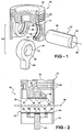
Figure 1 is an exploded perspective view of a piston assembly constructed according to one embodiment of the invention; -
Figure 2 is an enlarged fragmentary sectional view of the assembled components ofFigure 1 ; -
Figure 3 is an enlarged partially sectional plan view of the wrist pin; and -
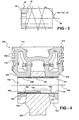
Figure 4 is a sectional view showing an alternative piston construction. - A piston assembly constructed according to one presently preferred embodiment of the invention is shown generally at 10 in
Figures 1 and 2 . The assembly has a piston body 12 (cast or forged) having anupper crown portion 14 formed withring grooves 16 for the accommodation of rings (not shown). A pair of laterally spaced pin bosses 18 depends from theupper crown portion 14 and is formed withpin bores 20 havingground running surfaces 22 fabricated of a metallic material, preferably steel. - A connecting
rod 24, preferably cast or forged from steel, has asmall end 26 formed with awrist pin bore 28 having aground running surface 30 alignable with thepin bores 20 of thepiston body 12, as shown inFigure 2 . - A
skirt 31 is provided, and may be formed separately from, thepiston body 12 from a lightweight material such as aluminum and joined by thewrist pin 32 as shown to provide an articulated structure. Alternatively, theskirt 31 may be formed of one piece with the piston body of the same material in a monobloc construction, as depicted at 3 inFigure 4 , wherein the same reference numerals are used to represent like features, but are offset by 100. - A
wrist pin 32 has abody 34 having an axis ofrotation 36 and a generally cylindricalouter surface 38. Theouter surface 38 is adapted for pivotal connection to thepin bores 20 of thepiston body 12 and the wrist pin bore 28 in thesmall end 26 of the connectingrod 24. - The
outer surface 38 of thewrist pin 32 is constructed for rotatable and/or pivotal connection to thepin bores 20 of thepiston body 12 and thewrist pin bore 28 of the connectingrod 24 such that the need to incorporate bushings, as are commonly used, in thepin bores 20 and thewrist pin bore 28 is eliminated. Preferably, to reduce the friction between theouter surface 38 of thewrist pin 32 and thebores coating 40 is applied to the runningsurfaces 22 of thepin bores 20, and to theground running surface 30 of thewrist pin bore 28. The manganese phosphate is engineered to provide at least in part the necessary tribological properties without having to incorporate the typical bushings within thebores - To inhibit damage from resulting between the
outer surface 38 of thewrist pin 32 and themanganese coating 40 within therespective bores outer surface 38 is produced having a surface roughness (Ra) with an arithmetic average deviation of 0.10 µm or less. Theouter surface 38 also has a Kurtosis value that is inversely proportional to the surface roughness (Ra) such that a product of the surface roughness (Ra) and the Kurtosis value (K) represented mathematically as (Ra x K) is between about 0.30 µm to 0.60 µm. In addition, theouter surface 38 has a skewness of about -1.0 to 0.0 and a lay angle α relative to theaxis 36 of about 85 to 95 degrees. Preferably, theouter surface 38 has a hardness of about 60 (HRC) or greater. - Skewness (Sk) can either take on a negative or a positive value. If the skewness is negative, this represents that a larger number of local maxima are above the mean as compared to a Gaussian distribution, which has a skewness value of zero. For a positive skewness, the converse is true, wherein a larger number of local maxima are below the mean as compared to that of a Gaussian distribution.
- Similarly, a surface with a low Kurtosis has a larger number of local maxima above the mean as compared to that of a Gaussian distribution, and a surface with a high Kurtosis has a larger number of local maxima below the mean as compared to that of a Gaussian distribution.
- The surface topography is preferably analyzed using a white light interferometry (WRI) method. In using (WRI), the calculations are based on a square area analysis. As such, rather than obtaining values based simply on a linear reading, as is commonly known, a more representative reading is obtained by taking into account a broader spectrum of the
outer surface 38. - It should be recognized that in obtaining the specified parameters for the various characteristics of the
outer surface 38 outlined above, that the need for bushings in either or both thepin bores 20 and thewrist pin bore 28 may be eliminated. However, if desired, a bushing may be used in either or both bores 20, 28. If bushings are used, then the useful life of the bushings is enhanced by reducing the amount of scuffing and/or wear to the bushing. - Obviously, many modifications and variations of the present invention are possible in light of the above teachings. It is, therefore, to be understood that within the scope of the appended claims, the invention may be practiced otherwise than as specifically described. The invention is defined by the claims.
Claims (5)
- A wrist pin (32) for joining a connecting rod (24) to a piston, said wrist pin (32) comprising:a generally cylindrical wrist pin body (34) having a central longitudinal axis (36) and an outer surface (38); and wherein said outer surface (38) is characterized by having an outer surface roughness of no greater than 0.10 µm, a Kurtosis value that is inversely proportional to the surface roughness such that the product of said Kurtosis value and said surface roughness is between about 0.3 µm to 0.60 µm, a skewness of about -1.0 to 0.0, and a lay angle relative to the axis (36) of about 85 to 95 degrees.
- A piston assembly comprising a wrist pin (32) according to claim 1, further comprising a piston having at least one wrist pin bore (20) and a connecting rod (24) having a wrist pin bore (28); wherein the wrist pin (32) is receivable in said bores to connect said piston to said connecting rod (24).
- A piston assembly comprising a wrist pin (32) according to claim 2 wherein said wrist pin bores (20, 28) are bushingless and covered by a low friction coating (40).
- A piston assembly comprising a wrist pin according to claim 3 wherein said low friction coating (40) comprises manganese phosphate.
- A piston assembly comprising a wrist pin according to anyone of claims 2 to 4, wherein said piston includes a piston body (12) formed with said wrist pin bore (20) and a piston skirt (31) formed as one piece with said piston body (12) of the same material.
Applications Claiming Priority (3)
| Application Number | Priority Date | Filing Date | Title |
|---|---|---|---|
| US44442103P | 2003-02-03 | 2003-02-03 | |
| US444421P | 2003-02-03 | ||
| PCT/US2004/003090 WO2004070238A2 (en) | 2003-02-03 | 2004-02-03 | Wrist pin |
Publications (3)
| Publication Number | Publication Date |
|---|---|
| EP1590584A2 EP1590584A2 (en) | 2005-11-02 |
| EP1590584A4 EP1590584A4 (en) | 2006-02-01 |
| EP1590584B1 true EP1590584B1 (en) | 2008-03-26 |
Family
ID=32850854
Family Applications (1)
| Application Number | Title | Priority Date | Filing Date |
|---|---|---|---|
| EP04707750A Expired - Lifetime EP1590584B1 (en) | 2003-02-03 | 2004-02-03 | Wrist pin |
Country Status (6)
| Country | Link |
|---|---|
| US (1) | US7024981B2 (en) |
| EP (1) | EP1590584B1 (en) |
| AT (1) | ATE390581T1 (en) |
| DE (1) | DE602004012709T2 (en) |
| ES (1) | ES2300745T3 (en) |
| WO (1) | WO2004070238A2 (en) |
Families Citing this family (13)
| Publication number | Priority date | Publication date | Assignee | Title |
|---|---|---|---|---|
| DE102005061063A1 (en) * | 2005-12-21 | 2007-06-28 | Mahle International Gmbh | Piston for internal combustion engine has hub borings in form of borings of circular internal outline with resin coating containing solid lubricant particles |
| US20080163751A1 (en) * | 2007-01-09 | 2008-07-10 | Vijay Subramanian | Coated piston and coating method |
| US8539928B2 (en) * | 2007-12-10 | 2013-09-24 | Federal-Mogul World Wide, Inc. | Piston assembly and connecting rod having a profiled wrist pin bore therefor |
| DE102008055194A1 (en) | 2008-12-30 | 2010-07-08 | Federal-Mogul Wiesbaden Gmbh | Slide |
| US8807109B2 (en) * | 2009-11-06 | 2014-08-19 | Federal-Mogul Corporation | Steel piston with cooling gallery and method of construction thereof |
| US9945480B2 (en) | 2011-06-30 | 2018-04-17 | Federal-Mogul Llc | Piston assembly including a polymer coating with hard particles applied to sliding surfaces |
| US9599148B2 (en) | 2011-10-17 | 2017-03-21 | Mahle International Gmbh | Thermal spray coating for connecting rod small end |
| KR20140083927A (en) | 2011-10-27 | 2014-07-04 | 페더럴-모걸 코오포레이숀 | Piston assembly including a polymer coating with hard particles applied to sliding surfaces |
| CN104870834B (en) * | 2012-12-20 | 2017-05-03 | 加特可株式会社 | Manufacturing method for hydraulic actuator device |
| CN106103785B (en) * | 2014-01-29 | 2020-02-14 | 马勒国际有限公司 | Piston with coated pin bores |
| CN107110063B (en) | 2014-10-30 | 2019-10-22 | 天纳克公司 | Piston |
| US10190622B2 (en) * | 2014-11-03 | 2019-01-29 | Tenneco Inc. | Wear resistant coating applied to connecting rod surfaces |
| US10926330B2 (en) | 2017-02-17 | 2021-02-23 | Tenneco Inc. | Steel piston with metallurgically bonded bushing and method of manufacturing |
Family Cites Families (13)
| Publication number | Priority date | Publication date | Assignee | Title |
|---|---|---|---|---|
| US4189932A (en) | 1976-12-20 | 1980-02-26 | Dana Corporation | Piston pin bore and method of finishing |
| US4124010A (en) | 1976-12-20 | 1978-11-07 | Dana Corporation | Piston pin bore and method of finishing |
| US4730548A (en) | 1985-02-02 | 1988-03-15 | Toyota Jidosha Kabushiki Kaisha | Light metal alloy piston |
| US4754608A (en) | 1987-01-21 | 1988-07-05 | Bertsch Peter K | Squeeze film bearing for Stirling cycle compressor pistons |
| JPH0821297A (en) | 1994-06-30 | 1996-01-23 | Yamaha Motor Co Ltd | Slide contact part structure of internal combustion engine |
| JPH08144842A (en) | 1994-11-24 | 1996-06-04 | Yamaha Motor Co Ltd | Diesel engine |
| US5893609A (en) | 1997-06-20 | 1999-04-13 | Mccord Winn Textron Inc. | Air pumping system for an automotive seat |
| US5884600A (en) | 1998-02-20 | 1999-03-23 | General Motors Corporation | Aluminum bore engine having wear and scuff-resistant aluminum piston |
| US6557457B1 (en) | 1999-12-01 | 2003-05-06 | Federal-Mogul World Wide, Inc. | Bushingless piston and connecting rod assembly and method of manufacture |
| JP2001295924A (en) * | 2000-04-11 | 2001-10-26 | Daido Steel Co Ltd | Piston pin and method of manufacturing the same |
| US20020157534A1 (en) | 2001-04-25 | 2002-10-31 | Deere & Company, A Delaware Corporation | Connecting rod bore profile for bushingless piston assembly |
| US6513477B1 (en) | 2001-09-19 | 2003-02-04 | Federal-Mogul World Wide, Inc. | Closed gallery piston having pin bore lubrication |
| US20040215545A1 (en) * | 2003-01-31 | 2004-10-28 | Kabushiki Kaisha Toshiba | Power trading risk management system |
-
2004
- 2004-02-03 US US10/770,930 patent/US7024981B2/en not_active Expired - Lifetime
- 2004-02-03 WO PCT/US2004/003090 patent/WO2004070238A2/en active Application Filing
- 2004-02-03 DE DE602004012709T patent/DE602004012709T2/en not_active Expired - Lifetime
- 2004-02-03 EP EP04707750A patent/EP1590584B1/en not_active Expired - Lifetime
- 2004-02-03 AT AT04707750T patent/ATE390581T1/en not_active IP Right Cessation
- 2004-02-03 ES ES04707750T patent/ES2300745T3/en not_active Expired - Lifetime
Also Published As
| Publication number | Publication date |
|---|---|
| US20040216605A1 (en) | 2004-11-04 |
| US7024981B2 (en) | 2006-04-11 |
| ATE390581T1 (en) | 2008-04-15 |
| WO2004070238A3 (en) | 2005-04-14 |
| DE602004012709T2 (en) | 2009-04-16 |
| DE602004012709D1 (en) | 2008-05-08 |
| WO2004070238A2 (en) | 2004-08-19 |
| EP1590584A4 (en) | 2006-02-01 |
| ES2300745T3 (en) | 2008-06-16 |
| EP1590584A2 (en) | 2005-11-02 |
Similar Documents
| Publication | Publication Date | Title |
|---|---|---|
| EP1590584B1 (en) | Wrist pin | |
| EP1812201B1 (en) | Method of manufacturing a connecting rod assembly for an internal combustion engine | |
| US8539928B2 (en) | Piston assembly and connecting rod having a profiled wrist pin bore therefor | |
| EP1812202B1 (en) | Method of manufacturing a connecting rod assembly for an internal combustion engine | |
| US8851029B2 (en) | Opposed-piston cylinder bore constructions with solid lubrication in the top ring reversal zones | |
| CN101839187A (en) | Internal combustion engine piston | |
| US10119613B2 (en) | Wrist pin and method of reducing wear between members thereof, connecting rod, piston and methods of constructing same | |
| US8613137B2 (en) | Connecting rod lubrication recess | |
| US20100300397A1 (en) | Connecting rod lubrication recess | |
| US6923153B2 (en) | Piston and connecting rod assembly having phosphatized bushingless connecting rod and profiled piston pin | |
| EP1697662B1 (en) | Phosphatized and bushingless piston and connecting rod assembly having an internal gallery and profiled piston pin | |
| US7603944B2 (en) | Piston assembly and wrist pin therefor providing a method of controlling rotation of the wrist pin within corresponding piston pin bores and connecting rod wrist pin bore | |
| JPH0819951B2 (en) | Sliding member of internal combustion engine | |
| JPH0743539Y2 (en) | Piston pin structure | |
| JPH0861016A (en) | Assembly camshaft |
Legal Events
| Date | Code | Title | Description |
|---|---|---|---|
| PUAI | Public reference made under article 153(3) epc to a published international application that has entered the european phase |
Free format text: ORIGINAL CODE: 0009012 |
|
| 17P | Request for examination filed |
Effective date: 20050803 |
|
| AK | Designated contracting states |
Kind code of ref document: A2 Designated state(s): AT BE BG CH CY CZ DE DK EE ES FI FR GB GR HU IE IT LI LU MC NL PT RO SE SI SK TR |
|
| AX | Request for extension of the european patent |
Extension state: AL LT LV MK |
|
| A4 | Supplementary search report drawn up and despatched |
Effective date: 20051220 |
|
| DAX | Request for extension of the european patent (deleted) | ||
| 17Q | First examination report despatched |
Effective date: 20060425 |
|
| RIN1 | Information on inventor provided before grant (corrected) |
Inventor name: MATSUO, EDUARDO Inventor name: NIGRO, ROBERTO, B. Inventor name: GAISER, RANDALL, R. Inventor name: HIGHUM, ERIC, A. |
|
| GRAP | Despatch of communication of intention to grant a patent |
Free format text: ORIGINAL CODE: EPIDOSNIGR1 |
|
| GRAS | Grant fee paid |
Free format text: ORIGINAL CODE: EPIDOSNIGR3 |
|
| GRAA | (expected) grant |
Free format text: ORIGINAL CODE: 0009210 |
|
| AK | Designated contracting states |
Kind code of ref document: B1 Designated state(s): AT BE BG CH CY CZ DE DK EE ES FI FR GB GR HU IE IT LI LU MC NL PT RO SE SI SK TR |
|
| REG | Reference to a national code |
Ref country code: GB Ref legal event code: FG4D |
|
| REG | Reference to a national code |
Ref country code: IE Ref legal event code: FG4D Ref country code: CH Ref legal event code: EP |
|
| REF | Corresponds to: |
Ref document number: 602004012709 Country of ref document: DE Date of ref document: 20080508 Kind code of ref document: P |
|
| REG | Reference to a national code |
Ref country code: ES Ref legal event code: FG2A Ref document number: 2300745 Country of ref document: ES Kind code of ref document: T3 |
|
| PG25 | Lapsed in a contracting state [announced via postgrant information from national office to epo] |
Ref country code: FI Free format text: LAPSE BECAUSE OF FAILURE TO SUBMIT A TRANSLATION OF THE DESCRIPTION OR TO PAY THE FEE WITHIN THE PRESCRIBED TIME-LIMIT Effective date: 20080326 |
|
| ET | Fr: translation filed | ||
| PG25 | Lapsed in a contracting state [announced via postgrant information from national office to epo] |
Ref country code: AT Free format text: LAPSE BECAUSE OF FAILURE TO SUBMIT A TRANSLATION OF THE DESCRIPTION OR TO PAY THE FEE WITHIN THE PRESCRIBED TIME-LIMIT Effective date: 20080326 |
|
| NLV1 | Nl: lapsed or annulled due to failure to fulfill the requirements of art. 29p and 29m of the patents act | ||
| PG25 | Lapsed in a contracting state [announced via postgrant information from national office to epo] |
Ref country code: BE Free format text: LAPSE BECAUSE OF FAILURE TO SUBMIT A TRANSLATION OF THE DESCRIPTION OR TO PAY THE FEE WITHIN THE PRESCRIBED TIME-LIMIT Effective date: 20080326 Ref country code: SI Free format text: LAPSE BECAUSE OF FAILURE TO SUBMIT A TRANSLATION OF THE DESCRIPTION OR TO PAY THE FEE WITHIN THE PRESCRIBED TIME-LIMIT Effective date: 20080326 |
|
| PG25 | Lapsed in a contracting state [announced via postgrant information from national office to epo] |
Ref country code: SE Free format text: LAPSE BECAUSE OF FAILURE TO SUBMIT A TRANSLATION OF THE DESCRIPTION OR TO PAY THE FEE WITHIN THE PRESCRIBED TIME-LIMIT Effective date: 20080626 Ref country code: SK Free format text: LAPSE BECAUSE OF FAILURE TO SUBMIT A TRANSLATION OF THE DESCRIPTION OR TO PAY THE FEE WITHIN THE PRESCRIBED TIME-LIMIT Effective date: 20080326 Ref country code: CZ Free format text: LAPSE BECAUSE OF FAILURE TO SUBMIT A TRANSLATION OF THE DESCRIPTION OR TO PAY THE FEE WITHIN THE PRESCRIBED TIME-LIMIT Effective date: 20080326 Ref country code: PT Free format text: LAPSE BECAUSE OF FAILURE TO SUBMIT A TRANSLATION OF THE DESCRIPTION OR TO PAY THE FEE WITHIN THE PRESCRIBED TIME-LIMIT Effective date: 20080901 |
|
| PG25 | Lapsed in a contracting state [announced via postgrant information from national office to epo] |
Ref country code: NL Free format text: LAPSE BECAUSE OF FAILURE TO SUBMIT A TRANSLATION OF THE DESCRIPTION OR TO PAY THE FEE WITHIN THE PRESCRIBED TIME-LIMIT Effective date: 20080326 Ref country code: RO Free format text: LAPSE BECAUSE OF FAILURE TO SUBMIT A TRANSLATION OF THE DESCRIPTION OR TO PAY THE FEE WITHIN THE PRESCRIBED TIME-LIMIT Effective date: 20080326 |
|
| PG25 | Lapsed in a contracting state [announced via postgrant information from national office to epo] |
Ref country code: DK Free format text: LAPSE BECAUSE OF FAILURE TO SUBMIT A TRANSLATION OF THE DESCRIPTION OR TO PAY THE FEE WITHIN THE PRESCRIBED TIME-LIMIT Effective date: 20080326 |
|
| PLBE | No opposition filed within time limit |
Free format text: ORIGINAL CODE: 0009261 |
|
| STAA | Information on the status of an ep patent application or granted ep patent |
Free format text: STATUS: NO OPPOSITION FILED WITHIN TIME LIMIT |
|
| 26N | No opposition filed |
Effective date: 20081230 |
|
| PG25 | Lapsed in a contracting state [announced via postgrant information from national office to epo] |
Ref country code: BG Free format text: LAPSE BECAUSE OF FAILURE TO SUBMIT A TRANSLATION OF THE DESCRIPTION OR TO PAY THE FEE WITHIN THE PRESCRIBED TIME-LIMIT Effective date: 20080626 Ref country code: EE Free format text: LAPSE BECAUSE OF FAILURE TO SUBMIT A TRANSLATION OF THE DESCRIPTION OR TO PAY THE FEE WITHIN THE PRESCRIBED TIME-LIMIT Effective date: 20080326 |
|
| PGFP | Annual fee paid to national office [announced via postgrant information from national office to epo] |
Ref country code: ES Payment date: 20090218 Year of fee payment: 6 |
|
| PGFP | Annual fee paid to national office [announced via postgrant information from national office to epo] |
Ref country code: GB Payment date: 20090106 Year of fee payment: 6 |
|
| PGFP | Annual fee paid to national office [announced via postgrant information from national office to epo] |
Ref country code: IT Payment date: 20090214 Year of fee payment: 6 |
|
| PG25 | Lapsed in a contracting state [announced via postgrant information from national office to epo] |
Ref country code: MC Free format text: LAPSE BECAUSE OF NON-PAYMENT OF DUE FEES Effective date: 20090228 Ref country code: CY Free format text: LAPSE BECAUSE OF FAILURE TO SUBMIT A TRANSLATION OF THE DESCRIPTION OR TO PAY THE FEE WITHIN THE PRESCRIBED TIME-LIMIT Effective date: 20080326 |
|
| REG | Reference to a national code |
Ref country code: CH Ref legal event code: PL |
|
| PG25 | Lapsed in a contracting state [announced via postgrant information from national office to epo] |
Ref country code: CH Free format text: LAPSE BECAUSE OF NON-PAYMENT OF DUE FEES Effective date: 20090228 Ref country code: LI Free format text: LAPSE BECAUSE OF NON-PAYMENT OF DUE FEES Effective date: 20090228 |
|
| PGFP | Annual fee paid to national office [announced via postgrant information from national office to epo] |
Ref country code: FR Payment date: 20090206 Year of fee payment: 6 |
|
| PG25 | Lapsed in a contracting state [announced via postgrant information from national office to epo] |
Ref country code: IE Free format text: LAPSE BECAUSE OF NON-PAYMENT OF DUE FEES Effective date: 20090203 |
|
| GBPC | Gb: european patent ceased through non-payment of renewal fee |
Effective date: 20100203 |
|
| PG25 | Lapsed in a contracting state [announced via postgrant information from national office to epo] |
Ref country code: GR Free format text: LAPSE BECAUSE OF FAILURE TO SUBMIT A TRANSLATION OF THE DESCRIPTION OR TO PAY THE FEE WITHIN THE PRESCRIBED TIME-LIMIT Effective date: 20080627 |
|
| REG | Reference to a national code |
Ref country code: FR Ref legal event code: ST Effective date: 20101029 |
|
| PG25 | Lapsed in a contracting state [announced via postgrant information from national office to epo] |
Ref country code: FR Free format text: LAPSE BECAUSE OF NON-PAYMENT OF DUE FEES Effective date: 20100301 |
|
| REG | Reference to a national code |
Ref country code: ES Ref legal event code: FD2A Effective date: 20110330 |
|
| PG25 | Lapsed in a contracting state [announced via postgrant information from national office to epo] |
Ref country code: IT Free format text: LAPSE BECAUSE OF NON-PAYMENT OF DUE FEES Effective date: 20100203 Ref country code: GB Free format text: LAPSE BECAUSE OF NON-PAYMENT OF DUE FEES Effective date: 20100203 |
|
| PG25 | Lapsed in a contracting state [announced via postgrant information from national office to epo] |
Ref country code: LU Free format text: LAPSE BECAUSE OF NON-PAYMENT OF DUE FEES Effective date: 20090203 |
|
| PG25 | Lapsed in a contracting state [announced via postgrant information from national office to epo] |
Ref country code: HU Free format text: LAPSE BECAUSE OF FAILURE TO SUBMIT A TRANSLATION OF THE DESCRIPTION OR TO PAY THE FEE WITHIN THE PRESCRIBED TIME-LIMIT Effective date: 20080927 |
|
| PG25 | Lapsed in a contracting state [announced via postgrant information from national office to epo] |
Ref country code: ES Free format text: LAPSE BECAUSE OF NON-PAYMENT OF DUE FEES Effective date: 20110317 |
|
| PG25 | Lapsed in a contracting state [announced via postgrant information from national office to epo] |
Ref country code: TR Free format text: LAPSE BECAUSE OF FAILURE TO SUBMIT A TRANSLATION OF THE DESCRIPTION OR TO PAY THE FEE WITHIN THE PRESCRIBED TIME-LIMIT Effective date: 20080326 |
|
| PG25 | Lapsed in a contracting state [announced via postgrant information from national office to epo] |
Ref country code: ES Free format text: LAPSE BECAUSE OF NON-PAYMENT OF DUE FEES Effective date: 20100204 |
|
| PGFP | Annual fee paid to national office [announced via postgrant information from national office to epo] |
Ref country code: DE Payment date: 20130228 Year of fee payment: 10 |
|
| REG | Reference to a national code |
Ref country code: DE Ref legal event code: R119 Ref document number: 602004012709 Country of ref document: DE |
|
| REG | Reference to a national code |
Ref country code: DE Ref legal event code: R119 Ref document number: 602004012709 Country of ref document: DE Effective date: 20140902 |
|
| PG25 | Lapsed in a contracting state [announced via postgrant information from national office to epo] |
Ref country code: DE Free format text: LAPSE BECAUSE OF NON-PAYMENT OF DUE FEES Effective date: 20140902 |