EP1590215B1 - A stabilizer leg for a truck - Google Patents
A stabilizer leg for a truck Download PDFInfo
- Publication number
- EP1590215B1 EP1590215B1 EP04705052A EP04705052A EP1590215B1 EP 1590215 B1 EP1590215 B1 EP 1590215B1 EP 04705052 A EP04705052 A EP 04705052A EP 04705052 A EP04705052 A EP 04705052A EP 1590215 B1 EP1590215 B1 EP 1590215B1
- Authority
- EP
- European Patent Office
- Prior art keywords
- stabilizer leg
- hydraulic
- track
- leg
- swivellable
- Prior art date
- Legal status (The legal status is an assumption and is not a legal conclusion. Google has not performed a legal analysis and makes no representation as to the accuracy of the status listed.)
- Expired - Lifetime
Links
- 239000003381 stabilizer Substances 0.000 title claims abstract description 55
- 230000007246 mechanism Effects 0.000 claims abstract description 11
- 238000006243 chemical reaction Methods 0.000 claims abstract description 8
- 230000000087 stabilizing effect Effects 0.000 claims description 5
- 230000005540 biological transmission Effects 0.000 claims description 4
- 230000006641 stabilisation Effects 0.000 claims 1
- 238000011105 stabilization Methods 0.000 claims 1
- 238000010276 construction Methods 0.000 abstract description 3
- 241001166076 Diapheromera femorata Species 0.000 description 2
- 239000000428 dust Substances 0.000 description 2
- 230000001133 acceleration Effects 0.000 description 1
- 238000005266 casting Methods 0.000 description 1
- 230000001419 dependent effect Effects 0.000 description 1
- 238000004519 manufacturing process Methods 0.000 description 1
- 239000000463 material Substances 0.000 description 1
- 238000003801 milling Methods 0.000 description 1
- 238000002360 preparation method Methods 0.000 description 1
- 238000003825 pressing Methods 0.000 description 1
- 230000007704 transition Effects 0.000 description 1
Images




Classifications
-
- B—PERFORMING OPERATIONS; TRANSPORTING
- B66—HOISTING; LIFTING; HAULING
- B66C—CRANES; LOAD-ENGAGING ELEMENTS OR DEVICES FOR CRANES, CAPSTANS, WINCHES, OR TACKLES
- B66C23/00—Cranes comprising essentially a beam, boom, or triangular structure acting as a cantilever and mounted for translatory of swinging movements in vertical or horizontal planes or a combination of such movements, e.g. jib-cranes, derricks, tower cranes
- B66C23/62—Constructional features or details
- B66C23/72—Counterweights or supports for balancing lifting couples
- B66C23/78—Supports, e.g. outriggers, for mobile cranes
- B66C23/80—Supports, e.g. outriggers, for mobile cranes hydraulically actuated
-
- B—PERFORMING OPERATIONS; TRANSPORTING
- B60—VEHICLES IN GENERAL
- B60S—SERVICING, CLEANING, REPAIRING, SUPPORTING, LIFTING, OR MANOEUVRING OF VEHICLES, NOT OTHERWISE PROVIDED FOR
- B60S9/00—Ground-engaging vehicle fittings for supporting, lifting, or manoeuvring the vehicle, wholly or in part, e.g. built-in jacks
- B60S9/02—Ground-engaging vehicle fittings for supporting, lifting, or manoeuvring the vehicle, wholly or in part, e.g. built-in jacks for only lifting or supporting
- B60S9/10—Ground-engaging vehicle fittings for supporting, lifting, or manoeuvring the vehicle, wholly or in part, e.g. built-in jacks for only lifting or supporting by fluid pressure
- B60S9/12—Ground-engaging vehicle fittings for supporting, lifting, or manoeuvring the vehicle, wholly or in part, e.g. built-in jacks for only lifting or supporting by fluid pressure of telescopic type
Definitions
- the invention relates to a swivellable hydraulic stabilizer leg for truck cranes and similar vehicles with a mechanism to swivel the stabilizer leg from an operational position to a transport position comprising a linear force transmission that is converted to a rotary movement at the bearing journal of the stabilizer leg.
- a truck is frequently fitted with a crane that is used for loading and unloading of goods. If the crane has a long reach, it is important that the area of support is as large as possible and furthermore has a firmer contact to the ground than that which may be provided by inflated truck tyres. For this reason such a truck is fitted with extendable beams that are pulled out sideways with respect to the truck, at least to the side where the load is disposed. At the end of the beam there is fitted a hydraulic cylinder that has a shoe for pressing against the ground. The piston is extended so far that the truck chassis remains horizontal when the crane is loaded.
- EP-A-658 509 describes the use of a toothed rack driven by a separate hydraulic cylinder for cooperation with a fixed pinion, but it is disadvantageous that the drive mechanism is completely open and subjected to heavy wear due to dust and gravel, as well as the fact that it leaves a downwards projecting rack when the stabilizer leg has been raised.
- EP-A-945 318 describes the use of a toothed rack driven from the piston of the stabilizer leg for cooperation with a fixed pinion, but this, too, has the disadvantage that the drive mechanism is completely open and subjected to heavy wear due to dust and gravel, as well as the fact that it leaves a downwards projecting rack when the stabilizer leg has been raised.
- EP-A-1 249 376 describes a hydraulic rotary piston motor fitted at the swivelling part. This is dustproof, but the manufacture of a rotary piston motor is expensive.
- WO-A-93/11981 demonstrates the use of a toggle joint mechanism driven by the piston of the stabilizer leg. This latter solution is very dependent on the absence of slack in the rod links. It is furthermore kinematically very sluggish in its movements, because part of the swivelling entails a large acceleration of the stabilizer leg.
- a mechanism according to the invention that is particular in that the conversion from linear to rotary movement occurs by tangential pressure on a number of rotational bodies that are lined up in a walking-stick shaped track with parallel walls that is constituted of a straight part and of an arc of a circle having an angle exceeding 90°, said track passing tangentially into said arc and being formed in a housing that is firmly joined to the stabilizer leg and surrounds its journal, said pressure being applied in the straight part of the track, and in that the innermost rotational body abuts a knob that is secured against rotation on said journal.
- a walking-stick shaped track is meant a track with parallel walls that is constituted of a straight part that passes tangentially into an arc of a circle having an .. angle exceeding 90°.
- Such a track is preferentially milled out of the material of a housing as mentioned, but it may obviously also be manufactured by casting and subsequent finishing by milling of the housing.
- a rotational body for use in the invention will typically be a cylindrical roller with a height corresponding to the depth of the track, while having a line contact to its neighbouring rollers, which permits the transmission of the compressive forces in a simple fashion.
- the first rotational body is acted upon in the straight part of the track by a rod that is acted upon by the piston in a hydraulic cylinder.
- a rod that is acted upon by the piston in a hydraulic cylinder.
- Such a cylinder may be fitted to the outside of the stabilizer leg or in a particularly advantageous embodiment be constituted by the hydraulic cylinder that is placed inside the stabilizer leg.
- the first rotational body in the straight part of the track is acted upon by a rod connection that transmits the movement of the piston rod of the stabilizing leg during retraction.
- the linear power transmission is hence constituted by a rod connection from the piston of the stabilizer leg to the first rotational body in the straight part of the track.
- the rod connection is supported in bushings close to the mouth of the cylinder of the stabilizing leg and close to the first rotational body, and it transmits a force in a sideways shifted parallel direction between these two bushings.
- the rod is controlled in direction, making it suitable for transmitting a linear force, and rotation.
- a converter for linear to rotating movement according to the invention may also be integrated with the locking device that is used for the normal functioning of the stabilizer leg, so that it does not swivel away from the vertical position, just because it is fitted with a mechanism for reversal when driving.
- the stabilizer leg with a swivelling mechanism are mounted on an extendable beam that is disposed partly above and close to the wheels of a vehicle, in which the beam is retracted to within the vertical plane defined by the outer sides of the vehicle's wheels.
- Such an extendable beam may be pulled in closer to the centre of the truck than known mechanical constructions, because there is no downwards projecting mechanical part when the stabilizer leg is swivelled upwards.
- Fig. 1 an extendable beam 1 with a fitted stabilizer leg 2.
- the beam is mounted in an extendable fashion on the chassis of a truck that carries a crane or a ladder.
- the stabilizer leg is fitted to the beam by means of a strong hinge 3 so that it may be turned in a plane perpendicular to the beam, and it may be locked in a manner not shown to the beam by means of a releasable fitting 4.
- the stabilizer leg consists of a hydraulic cylinder 5 with a piston that is visible at the piston rod 6.
- a shoe 7 is fitted permitting a certain tilt in a joint 8.
- the piston rod 6 In use the piston rod 6 is extended, until the stabilizer leg carries a suitable part of the weight of the truck, but during preparation for driving away the piston is retracted.
- the piston rod 6 is supplied with a collar 9 that may interact with an abutting surface on a stiff rod connection 11, 12, 13 mounted axially displaceable on the outside of the cylinder 5.
- the rod connection transmits pressure and linear movement from the collar 9 to a converter 14 for linear to rotational movement.
- This converter is permanently mounted on the stabilizer leg 2 and is only active when the releasable fitting 4 has been released.
- the rod connection is displaced in parallel and transmits a force by means of a skewed part 12 and the rod is supported in two bushings 15, 16 and a bore 17 in the converter 14.
- the collar 9 is pressed against the abutment 10 while the piston rod 6 is moved into the cylinder 5, the pressure and movement are transmitted to the other end 13 of the rod.
- the converter 14 starts turning around the fixed journal 3' in the hinge 3, and the stabilizer leg is swivelled around to the position shown in Fig. 2.
- the beam 1 may be retracted into the chassis, i.e. to the right in the figure.
- Fig. 2 and Fig. 3 there is similarly shown the placement of a release 4a for the fitting 4.
- Fig. 4 the converter 14 is shown opened, i.e. an essentially plane lid has been removed, and in enlargement.
- the end 13 of the rod is supported in a suitable bushing in the bore 17 into a track 18, 19, which consists of two parts, a straight part 18 which may receive the end 13 of the rod and a circular part 19.
- the circular part is concentric with the fixed journal 3' in the hinge 3 that is surrounded by the converter 14.
- a knob 20 that is firmly connected to the shaft 3' in that both are mounted on the same strong carrier for the stabilizer leg (2).
- the stabilizer leg according to the invention may be used in conjunction with any vehicle, in which there is desired a possibility for swivelling a stabilizer leg upwards to a vertical position without the use of a complicated and expensive hydraulic motor.
- a stabilizer leg according to the invention is not constructively tied to being moved in a plane perpendicular to an extendable beam, but may indeed move in the same plane as the beam.
Landscapes
- Engineering & Computer Science (AREA)
- Mechanical Engineering (AREA)
- Physics & Mathematics (AREA)
- Fluid Mechanics (AREA)
- Jib Cranes (AREA)
- Compositions Of Macromolecular Compounds (AREA)
- Vehicle Cleaning, Maintenance, Repair, Refitting, And Outriggers (AREA)
- Vehicle Body Suspensions (AREA)
Abstract
Description
- The invention relates to a swivellable hydraulic stabilizer leg for truck cranes and similar vehicles with a mechanism to swivel the stabilizer leg from an operational position to a transport position comprising a linear force transmission that is converted to a rotary movement at the bearing journal of the stabilizer leg.
- A truck is frequently fitted with a crane that is used for loading and unloading of goods. If the crane has a long reach, it is important that the area of support is as large as possible and furthermore has a firmer contact to the ground than that which may be provided by inflated truck tyres. For this reason such a truck is fitted with extendable beams that are pulled out sideways with respect to the truck, at least to the side where the load is disposed. At the end of the beam there is fitted a hydraulic cylinder that has a shoe for pressing against the ground. The piston is extended so far that the truck chassis remains horizontal when the crane is loaded. There is rarely room to let the cylinder hang downwards during transport, even though the piston may be retracted, and for this reason swivelling joints have been developed so that the cylinder is swivelled in the opposite direction and points upwards during transport. Because of the load and worker's protection rules this rotation frequently occurs by hydraulic power, e.g. as described in the following patent publications.
-
EP-A-658 509 -
EP-A-945 318 -
EP-A-1 249 376 describes a hydraulic rotary piston motor fitted at the swivelling part. This is dustproof, but the manufacture of a rotary piston motor is expensive. -
WO-A-93/11981 - There is hence a need for a mechanism that does not display the weakness of the open mechanisms or the cost of having a built-in hydraulic motor. This is obtained in a mechanism according to the invention that is particular in that the conversion from linear to rotary movement occurs by tangential pressure on a number of rotational bodies that are lined up in a walking-stick shaped track with parallel walls that is constituted of a straight part and of an arc of a circle having an angle exceeding 90°, said track passing tangentially into said arc and being formed in a housing that is firmly joined to the stabilizer leg and surrounds its journal, said pressure being applied in the straight part of the track, and in that the innermost rotational body abuts a knob that is secured against rotation on said journal. By the term "a walking-stick shaped track" is meant a track with parallel walls that is constituted of a straight part that passes tangentially into an arc of a circle having an .. angle exceeding 90°. Such a track is preferentially milled out of the material of a housing as mentioned, but it may obviously also be manufactured by casting and subsequent finishing by milling of the housing. A rotational body for use in the invention will typically be a cylindrical roller with a height corresponding to the depth of the track, while having a line contact to its neighbouring rollers, which permits the transmission of the compressive forces in a simple fashion.
- In an advantageous embodiment the first rotational body is acted upon in the straight part of the track by a rod that is acted upon by the piston in a hydraulic cylinder. Such a cylinder may be fitted to the outside of the stabilizer leg or in a particularly advantageous embodiment be constituted by the hydraulic cylinder that is placed inside the stabilizer leg.
- According to a further advantageous embodiment of the invention the first rotational body in the straight part of the track is acted upon by a rod connection that transmits the movement of the piston rod of the stabilizing leg during retraction. The linear power transmission is hence constituted by a rod connection from the piston of the stabilizer leg to the first rotational body in the straight part of the track.
- According to a further advantageous embodiment of the invention the rod connection is supported in bushings close to the mouth of the cylinder of the stabilizing leg and close to the first rotational body, and it transmits a force in a sideways shifted parallel direction between these two bushings. Thereby the rod is controlled in direction, making it suitable for transmitting a linear force, and rotation.
- A converter for linear to rotating movement according to the invention may also be integrated with the locking device that is used for the normal functioning of the stabilizer leg, so that it does not swivel away from the vertical position, just because it is fitted with a mechanism for reversal when driving.
- In an advantageous use of the invention the stabilizer leg with a swivelling mechanism are mounted on an extendable beam that is disposed partly above and close to the wheels of a vehicle, in which the beam is retracted to within the vertical plane defined by the outer sides of the vehicle's wheels. Such an extendable beam may be pulled in closer to the centre of the truck than known mechanical constructions, because there is no downwards projecting mechanical part when the stabilizer leg is swivelled upwards.
- The invention will be described in greater detail with reference to the drawing, in which
- Fig. 1 shows a stabilizer leg with the cylinder almost completely retracted,
- Fig. 2 shows a stabilizer leg, in which the cylinder is still more retracted, whereby the stabilizer leg has swung to horizontal position,
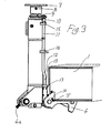
- Fig. 3 shows a stabilizer leg, in which the cylinder is fully retracted, whereby the stabilizer leg has swung completely to a vertical position,
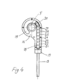
- Fig. 4 shows the conversion of linear movement to a rotational movement in the start position corresponding to Fig. 1,
- Fig. 5 shows the conversion of linear movement to a rotational movement in the start position corresponding to Fig. 2, and
- Fig. 6 shows the conversion of linear movement to a rotational movement in the start position corresponding to Fig. 3.
- In Fig. 1 is shown an extendable beam 1 with a fitted
stabilizer leg 2. The beam is mounted in an extendable fashion on the chassis of a truck that carries a crane or a ladder. The stabilizer leg is fitted to the beam by means of astrong hinge 3 so that it may be turned in a plane perpendicular to the beam, and it may be locked in a manner not shown to the beam by means of areleasable fitting 4. The stabilizer leg consists of ahydraulic cylinder 5 with a piston that is visible at the piston rod 6. At the end of the piston rod ashoe 7 is fitted permitting a certain tilt in ajoint 8. In use the piston rod 6 is extended, until the stabilizer leg carries a suitable part of the weight of the truck, but during preparation for driving away the piston is retracted. The piston rod 6 is supplied with acollar 9 that may interact with an abutting surface on astiff rod connection cylinder 5. The rod connection transmits pressure and linear movement from thecollar 9 to aconverter 14 for linear to rotational movement. This converter is permanently mounted on thestabilizer leg 2 and is only active when thereleasable fitting 4 has been released. - As shown in the present embodiment, the rod connection is displaced in parallel and transmits a force by means of a
skewed part 12 and the rod is supported in twobushings bore 17 in theconverter 14. When thecollar 9 is pressed against theabutment 10 while the piston rod 6 is moved into thecylinder 5, the pressure and movement are transmitted to theother end 13 of the rod. Theconverter 14 starts turning around the fixed journal 3' in thehinge 3, and the stabilizer leg is swivelled around to the position shown in Fig. 2. By further retraction of the piston rod 6 the movement continues until the vertical position shown in Fig. 3 is reached. Subsequently the beam 1 may be retracted into the chassis, i.e. to the right in the figure. In Fig. 2 and Fig. 3 there is similarly shown the placement of arelease 4a for thefitting 4. - In Fig. 4 the
converter 14 is shown opened, i.e. an essentially plane lid has been removed, and in enlargement. Theend 13 of the rod is supported in a suitable bushing in thebore 17 into atrack straight part 18 which may receive theend 13 of the rod and acircular part 19. The circular part is concentric with the fixed journal 3' in thehinge 3 that is surrounded by theconverter 14. At the transition between the two parts there is provided aknob 20 that is firmly connected to the shaft 3' in that both are mounted on the same strong carrier for the stabilizer leg (2). Between theend 13 of the rod and theknob 20 there are disposed a number of cylindrical rollers 21-27, which are fitted well lubricated in thetrack 18. When theend 13 of the rod is pressed into thetrack 18 due to the force P from the piston rod 6 via thecollar 9, theabutment 10, and therod knob 20. Due to the reaction force, the housing for theconverter 14 is turned, and thereby the stabilizer leg 1 is turned as well. Thereby the positions shown in Fig. 5 and Fig. 6 are reached. The movement will be quite even, because the transfer of the force causes a linear variation of the angle, and the force is always acting perpendicular to theknob 20, because the reaction forces are taken by thecircular track 19. - In Fig. 6 the
end 13 of the rod has reached the end of thestraight track 18 and the rolls 21-27 are all inside thecircular track 19. - The combination of a track with vertical sides that is simple to mill and the use of cylindrical rolls as rotational bodies make it very easy to adapt the construction to the dimensions of existing rotatable stabilizer legs, whereby the advantages of the invention may be obtained by later fitting to hydraulic stabilizer legs that function well per se. Similarly, the torque required to enable the stabilizer leg to pass the horizontal position between the two vertical positions may be obtained by the use of a smaller hydraulic force by making the radius in the circular track, and hence the housing, larger than shown in the illustrated embodiment. In this case the number of rotational bodies should be increased.
- It is within the abilities of the skilled person to provide means for creating the required force to commence the movement of the stabilizer leg from vertical upwards to the downwards swivelling to vertical downwards. For instance a person may observe the suitability of the ground for each individual stabilizer leg and in this conjunction with this perform a manual pull in the stabilizer leg, but there may also be provided a spring force that is counteracted during the retraction and swivelling of the stabilizer leg.
- It would appear obvious that the stabilizer leg according to the invention may be used in conjunction with any vehicle, in which there is desired a possibility for swivelling a stabilizer leg upwards to a vertical position without the use of a complicated and expensive hydraulic motor. A stabilizer leg according to the invention is not constructively tied to being moved in a plane perpendicular to an extendable beam, but may indeed move in the same plane as the beam.
Claims (6)
- A swivellable (3) hydraulic stabilizer leg (2) for truck cranes and similar vehicles with a mechanism (14) to swivel the stabilizer leg from an operational position to a transport position comprising a linear force transmission (13) that is converted to a rotary movement at the bearing journal (3') of the stabilizer leg, characterized in that the conversion from linear to rotary movement occurs by tangential pressure on a number of rotational bodies (21-27), that are lined up in a track (18, 19) with parallel walls that is constituted of a straight part (18) and of an arc (19) of a circle having an angle exceeding 90°, said track passing tangentially into said arc (19) and being formed in a housing that is firmly joined to the stabilizer leg (2) and surrounds its journal (3'), said pressure being applied in the straight part of the track, and in that the innermost rotational body (27) abuts a knob (20) that is secured against rotation on said journal (3').
- A swivellable hydraulic stabilizer leg according to claim 1,
characterized in that the first rotational body (21) is acted upon in the straight part (18) of the track by a rod (13) that is acted upon by the piston in a hydraulic cylinder. - A swivellable hydraulic stabilizer leg according to claim 2,
characterized in that the first rotational body (21) in the straight part (18) of the track is acted upon by a rod connection (11, 12, 13) that transmits the movement of the piston rod (6) of the stabilizing leg (2) during retraction. - A swivellable hydraulic stabilizer leg according to claim 3,
characterized in that the rod connection (11, 12, 13) is supported in bushings (14, 16) close to the mouth of the cylinder of the stabilizing leg and close to (17) the first rotational body (21) and that it transmits a force in a sideways shifted parallel direction (12) between these two bushings. - Use of a swivellable hydraulic stabilizer leg according to any of the preceding claims for support of the chassis of a vehicle, whereby it is mounted on an extendable beam (1) that projects from the chassis and is disposed partly above and close to the wheels of the vehicle, characterized in that when stabilization is desired the extendable beam (1) is extended from the vehicle chassis at least to the extent required to enable the stabilizer leg to move through a half-circle from a position pointing vertically upwards to a position pointing vertically downwards.
- Use of a swivellable hydraulic stabilizer leg according to any of the claims 1-5 in conjunction with withdrawal from a stabilizing position, whereby it is mounted on an extendable beam (1) that is disposed close to the wheels of a vehicle, characterized in that the hydraulic stabilizer leg (2) is shortened, whereby the last part of the movement causes rotation through a half-circle from a position pointing vertically downwards to a position pointing vertically upwards, whereupon the end of the beam (1) with the stabilizer leg (2) is retracted to within the vertical plane defined by the outer sides of the vehicle's wheels.
Applications Claiming Priority (5)
| Application Number | Priority Date | Filing Date | Title |
|---|---|---|---|
| DK200300097 | 2003-01-24 | ||
| DKPA200300097 | 2003-01-24 | ||
| DK200300241 | 2003-02-18 | ||
| DKPA200300241 | 2003-02-18 | ||
| PCT/DK2004/000051 WO2004065188A1 (en) | 2003-01-24 | 2004-01-26 | A stabilizer leg for a truck |
Publications (2)
| Publication Number | Publication Date |
|---|---|
| EP1590215A1 EP1590215A1 (en) | 2005-11-02 |
| EP1590215B1 true EP1590215B1 (en) | 2007-06-13 |
Family
ID=32773410
Family Applications (1)
| Application Number | Title | Priority Date | Filing Date |
|---|---|---|---|
| EP04705052A Expired - Lifetime EP1590215B1 (en) | 2003-01-24 | 2004-01-26 | A stabilizer leg for a truck |
Country Status (5)
| Country | Link |
|---|---|
| EP (1) | EP1590215B1 (en) |
| AT (1) | ATE364537T1 (en) |
| DE (1) | DE602004006963T2 (en) |
| DK (1) | DK1590215T3 (en) |
| WO (1) | WO2004065188A1 (en) |
Cited By (1)
| Publication number | Priority date | Publication date | Assignee | Title |
|---|---|---|---|---|
| WO2020142821A1 (en) * | 2019-01-09 | 2020-07-16 | Bosch Rexroth Ltda | Supporting and stabilizing system for goods vehicles that can be coupled to a tractor unit |
Families Citing this family (4)
| Publication number | Priority date | Publication date | Assignee | Title |
|---|---|---|---|---|
| CN111493465A (en) * | 2020-04-23 | 2020-08-07 | 杭州富阳林长发科技有限公司 | Ground-grasping type outdoor mountain-climbing walking stick based on force action principle |
| DE102022115586A1 (en) | 2022-06-22 | 2023-12-28 | Anton Fischbacher e.K. | Side support for a crane vehicle |
| CN115783938B (en) * | 2022-11-17 | 2026-02-10 | 中交二航局第四工程有限公司 | A conversion device for attachment connection of a lift and its design and installation method |
| CN116553407B (en) * | 2023-05-31 | 2025-10-24 | 徐州建机工程机械有限公司 | Steering underframe for tower crane, tower crane, and steering method of the steering underframe |
Family Cites Families (4)
| Publication number | Priority date | Publication date | Assignee | Title |
|---|---|---|---|---|
| DE1267397B (en) * | 1966-06-18 | 1968-05-02 | Bilstein August Fa | Supporting device for vehicles, especially road vehicles with mounted crane |
| DE3500221A1 (en) * | 1985-01-05 | 1986-07-10 | Haacon Hebetechnik GmbH, 6982 Freudenberg | HEIGHT-ADJUSTABLE SUPPORT DEVICE, IN PARTICULAR SEMI-TRAILER SUPPORT |
| SE504368C2 (en) * | 1995-05-03 | 1997-01-20 | Hiab Forest Ab | Support legs |
| EP0945318A1 (en) * | 1998-03-23 | 1999-09-29 | F.LLI FERRARI S.p.A. | Stabiliser leg for a load carrying vehicle |
-
2004
- 2004-01-26 EP EP04705052A patent/EP1590215B1/en not_active Expired - Lifetime
- 2004-01-26 DE DE602004006963T patent/DE602004006963T2/en not_active Expired - Lifetime
- 2004-01-26 AT AT04705052T patent/ATE364537T1/en not_active IP Right Cessation
- 2004-01-26 WO PCT/DK2004/000051 patent/WO2004065188A1/en not_active Ceased
- 2004-01-26 DK DK04705052T patent/DK1590215T3/en active
Cited By (1)
| Publication number | Priority date | Publication date | Assignee | Title |
|---|---|---|---|---|
| WO2020142821A1 (en) * | 2019-01-09 | 2020-07-16 | Bosch Rexroth Ltda | Supporting and stabilizing system for goods vehicles that can be coupled to a tractor unit |
Also Published As
| Publication number | Publication date |
|---|---|
| WO2004065188A1 (en) | 2004-08-05 |
| DE602004006963D1 (en) | 2007-07-26 |
| DE602004006963T2 (en) | 2008-02-21 |
| ATE364537T1 (en) | 2007-07-15 |
| DK1590215T3 (en) | 2008-01-02 |
| EP1590215A1 (en) | 2005-11-02 |
Similar Documents
| Publication | Publication Date | Title |
|---|---|---|
| US6283315B1 (en) | Crane, preferably a derrick crane | |
| EP3947110B1 (en) | Lift steering systems and methods | |
| EP1603771B1 (en) | Rotatable and articulated material handling apparatus | |
| US9346497B2 (en) | Variable tread width vehicle | |
| US6089388A (en) | Mobile crane | |
| EP1594775B1 (en) | Chocking apparatus | |
| CN101712439A (en) | Crane transition auxiliary device, transport trailer and method for dismantling crane | |
| MX2007013265A (en) | Mobile lift crane with variable position counterweight. | |
| EP3724124B1 (en) | Crane with wheels having variable camber angle | |
| JP2003521429A (en) | Working platform with rotary actuator | |
| US20100078403A1 (en) | Adjusting mechanism for a winch | |
| US20130094000A1 (en) | Camera crane mobile base | |
| EP1484233A2 (en) | Hydraulic steering mechanism and its support mechanism | |
| CN201580913U (en) | Crane transition auxiliary device, transportation trailer | |
| US11453577B2 (en) | Vehicle crane system for transporting an attachment part, in particular a main jib of a vehicle crane | |
| EP1590215A1 (en) | A stabilizer leg for a truck | |
| US5213222A (en) | Mobil crane | |
| US20210292136A1 (en) | Vehicle crane system having an attachment part transporting unit for a bracing device, in particular a lateral superlift, of a vehicle crane | |
| US4660843A (en) | Method and apparatus for varying a vehicle wheelbase | |
| AU2006257082B2 (en) | Tailgate | |
| US3963130A (en) | Coil unloader | |
| US6217044B1 (en) | Steerable and retractable wheels for multi-purpose carriage | |
| CN214401349U (en) | Mobile floor-processing machine comprising a functional device which can be coupled to a machine frame in a releasable manner, preferably without tools | |
| US8534415B2 (en) | Center-pivot steering articulated vehicle with load lifting trailer | |
| CN111183833B (en) | Consignment vehicle landing gear structure and climate cabin of a climate cabin container |
Legal Events
| Date | Code | Title | Description |
|---|---|---|---|
| PUAI | Public reference made under article 153(3) epc to a published international application that has entered the european phase |
Free format text: ORIGINAL CODE: 0009012 |
|
| 17P | Request for examination filed |
Effective date: 20050824 |
|
| AK | Designated contracting states |
Kind code of ref document: A1 Designated state(s): AT BE BG CH CY CZ DE DK EE ES FI FR GB GR HU IE IT LI LU MC NL PT RO SE SI SK TR |
|
| AX | Request for extension of the european patent |
Extension state: AL LT LV MK |
|
| DAX | Request for extension of the european patent (deleted) | ||
| GRAP | Despatch of communication of intention to grant a patent |
Free format text: ORIGINAL CODE: EPIDOSNIGR1 |
|
| RIC1 | Information provided on ipc code assigned before grant |
Ipc: B60S 9/02 20060101AFI20061116BHEP Ipc: B60S 9/12 20060101ALI20061116BHEP Ipc: B66C 23/80 20060101ALI20061116BHEP Ipc: B66C 23/78 20060101ALI20061116BHEP |
|
| GRAS | Grant fee paid |
Free format text: ORIGINAL CODE: EPIDOSNIGR3 |
|
| GRAA | (expected) grant |
Free format text: ORIGINAL CODE: 0009210 |
|
| AK | Designated contracting states |
Kind code of ref document: B1 Designated state(s): AT BE BG CH CY CZ DE DK EE ES FI FR GB GR HU IE IT LI LU MC NL PT RO SE SI SK TR |
|
| PG25 | Lapsed in a contracting state [announced via postgrant information from national office to epo] |
Ref country code: LI Free format text: LAPSE BECAUSE OF FAILURE TO SUBMIT A TRANSLATION OF THE DESCRIPTION OR TO PAY THE FEE WITHIN THE PRESCRIBED TIME-LIMIT Effective date: 20070613 Ref country code: CH Free format text: LAPSE BECAUSE OF FAILURE TO SUBMIT A TRANSLATION OF THE DESCRIPTION OR TO PAY THE FEE WITHIN THE PRESCRIBED TIME-LIMIT Effective date: 20070613 |
|
| REG | Reference to a national code |
Ref country code: GB Ref legal event code: FG4D |
|
| REG | Reference to a national code |
Ref country code: CH Ref legal event code: EP |
|
| REG | Reference to a national code |
Ref country code: IE Ref legal event code: FG4D |
|
| REF | Corresponds to: |
Ref document number: 602004006963 Country of ref document: DE Date of ref document: 20070726 Kind code of ref document: P |
|
| PG25 | Lapsed in a contracting state [announced via postgrant information from national office to epo] |
Ref country code: SE Free format text: LAPSE BECAUSE OF FAILURE TO SUBMIT A TRANSLATION OF THE DESCRIPTION OR TO PAY THE FEE WITHIN THE PRESCRIBED TIME-LIMIT Effective date: 20070913 |
|
| PG25 | Lapsed in a contracting state [announced via postgrant information from national office to epo] |
Ref country code: AT Free format text: LAPSE BECAUSE OF FAILURE TO SUBMIT A TRANSLATION OF THE DESCRIPTION OR TO PAY THE FEE WITHIN THE PRESCRIBED TIME-LIMIT Effective date: 20070613 |
|
| NLV1 | Nl: lapsed or annulled due to failure to fulfill the requirements of art. 29p and 29m of the patents act | ||
| REG | Reference to a national code |
Ref country code: CH Ref legal event code: PL |
|
| PG25 | Lapsed in a contracting state [announced via postgrant information from national office to epo] |
Ref country code: BE Free format text: LAPSE BECAUSE OF FAILURE TO SUBMIT A TRANSLATION OF THE DESCRIPTION OR TO PAY THE FEE WITHIN THE PRESCRIBED TIME-LIMIT Effective date: 20070613 |
|
| REG | Reference to a national code |
Ref country code: DK Ref legal event code: T3 |
|
| PG25 | Lapsed in a contracting state [announced via postgrant information from national office to epo] |
Ref country code: ES Free format text: LAPSE BECAUSE OF FAILURE TO SUBMIT A TRANSLATION OF THE DESCRIPTION OR TO PAY THE FEE WITHIN THE PRESCRIBED TIME-LIMIT Effective date: 20070924 Ref country code: SI Free format text: LAPSE BECAUSE OF FAILURE TO SUBMIT A TRANSLATION OF THE DESCRIPTION OR TO PAY THE FEE WITHIN THE PRESCRIBED TIME-LIMIT Effective date: 20070613 Ref country code: CZ Free format text: LAPSE BECAUSE OF FAILURE TO SUBMIT A TRANSLATION OF THE DESCRIPTION OR TO PAY THE FEE WITHIN THE PRESCRIBED TIME-LIMIT Effective date: 20070613 Ref country code: NL Free format text: LAPSE BECAUSE OF FAILURE TO SUBMIT A TRANSLATION OF THE DESCRIPTION OR TO PAY THE FEE WITHIN THE PRESCRIBED TIME-LIMIT Effective date: 20070613 Ref country code: PT Free format text: LAPSE BECAUSE OF FAILURE TO SUBMIT A TRANSLATION OF THE DESCRIPTION OR TO PAY THE FEE WITHIN THE PRESCRIBED TIME-LIMIT Effective date: 20071113 Ref country code: BG Free format text: LAPSE BECAUSE OF FAILURE TO SUBMIT A TRANSLATION OF THE DESCRIPTION OR TO PAY THE FEE WITHIN THE PRESCRIBED TIME-LIMIT Effective date: 20070913 |
|
| EN | Fr: translation not filed | ||
| PG25 | Lapsed in a contracting state [announced via postgrant information from national office to epo] |
Ref country code: SK Free format text: LAPSE BECAUSE OF FAILURE TO SUBMIT A TRANSLATION OF THE DESCRIPTION OR TO PAY THE FEE WITHIN THE PRESCRIBED TIME-LIMIT Effective date: 20070613 |
|
| PLBE | No opposition filed within time limit |
Free format text: ORIGINAL CODE: 0009261 |
|
| STAA | Information on the status of an ep patent application or granted ep patent |
Free format text: STATUS: NO OPPOSITION FILED WITHIN TIME LIMIT |
|
| PG25 | Lapsed in a contracting state [announced via postgrant information from national office to epo] |
Ref country code: GR Free format text: LAPSE BECAUSE OF FAILURE TO SUBMIT A TRANSLATION OF THE DESCRIPTION OR TO PAY THE FEE WITHIN THE PRESCRIBED TIME-LIMIT Effective date: 20070914 Ref country code: IT Free format text: LAPSE BECAUSE OF FAILURE TO SUBMIT A TRANSLATION OF THE DESCRIPTION OR TO PAY THE FEE WITHIN THE PRESCRIBED TIME-LIMIT Effective date: 20070613 |
|
| 26N | No opposition filed |
Effective date: 20080314 |
|
| PG25 | Lapsed in a contracting state [announced via postgrant information from national office to epo] |
Ref country code: RO Free format text: LAPSE BECAUSE OF FAILURE TO SUBMIT A TRANSLATION OF THE DESCRIPTION OR TO PAY THE FEE WITHIN THE PRESCRIBED TIME-LIMIT Effective date: 20070613 |
|
| PG25 | Lapsed in a contracting state [announced via postgrant information from national office to epo] |
Ref country code: FR Free format text: LAPSE BECAUSE OF FAILURE TO SUBMIT A TRANSLATION OF THE DESCRIPTION OR TO PAY THE FEE WITHIN THE PRESCRIBED TIME-LIMIT Effective date: 20080208 |
|
| PG25 | Lapsed in a contracting state [announced via postgrant information from national office to epo] |
Ref country code: MC Free format text: LAPSE BECAUSE OF NON-PAYMENT OF DUE FEES Effective date: 20080131 |
|
| PG25 | Lapsed in a contracting state [announced via postgrant information from national office to epo] |
Ref country code: EE Free format text: LAPSE BECAUSE OF FAILURE TO SUBMIT A TRANSLATION OF THE DESCRIPTION OR TO PAY THE FEE WITHIN THE PRESCRIBED TIME-LIMIT Effective date: 20070613 Ref country code: IE Free format text: LAPSE BECAUSE OF NON-PAYMENT OF DUE FEES Effective date: 20080128 |
|
| PG25 | Lapsed in a contracting state [announced via postgrant information from national office to epo] |
Ref country code: FI Free format text: LAPSE BECAUSE OF FAILURE TO SUBMIT A TRANSLATION OF THE DESCRIPTION OR TO PAY THE FEE WITHIN THE PRESCRIBED TIME-LIMIT Effective date: 20070613 |
|
| PG25 | Lapsed in a contracting state [announced via postgrant information from national office to epo] |
Ref country code: CY Free format text: LAPSE BECAUSE OF FAILURE TO SUBMIT A TRANSLATION OF THE DESCRIPTION OR TO PAY THE FEE WITHIN THE PRESCRIBED TIME-LIMIT Effective date: 20070613 |
|
| PG25 | Lapsed in a contracting state [announced via postgrant information from national office to epo] |
Ref country code: LU Free format text: LAPSE BECAUSE OF NON-PAYMENT OF DUE FEES Effective date: 20080126 Ref country code: HU Free format text: LAPSE BECAUSE OF FAILURE TO SUBMIT A TRANSLATION OF THE DESCRIPTION OR TO PAY THE FEE WITHIN THE PRESCRIBED TIME-LIMIT Effective date: 20071214 |
|
| PG25 | Lapsed in a contracting state [announced via postgrant information from national office to epo] |
Ref country code: TR Free format text: LAPSE BECAUSE OF FAILURE TO SUBMIT A TRANSLATION OF THE DESCRIPTION OR TO PAY THE FEE WITHIN THE PRESCRIBED TIME-LIMIT Effective date: 20070613 |
|
| PGFP | Annual fee paid to national office [announced via postgrant information from national office to epo] |
Ref country code: GB Payment date: 20201207 Year of fee payment: 18 |
|
| PGFP | Annual fee paid to national office [announced via postgrant information from national office to epo] |
Ref country code: DE Payment date: 20201207 Year of fee payment: 18 |
|
| REG | Reference to a national code |
Ref country code: DE Ref legal event code: R119 Ref document number: 602004006963 Country of ref document: DE |
|
| GBPC | Gb: european patent ceased through non-payment of renewal fee |
Effective date: 20220126 |
|
| PG25 | Lapsed in a contracting state [announced via postgrant information from national office to epo] |
Ref country code: GB Free format text: LAPSE BECAUSE OF NON-PAYMENT OF DUE FEES Effective date: 20220126 Ref country code: DE Free format text: LAPSE BECAUSE OF NON-PAYMENT OF DUE FEES Effective date: 20220802 |
|
| PGFP | Annual fee paid to national office [announced via postgrant information from national office to epo] |
Ref country code: DK Payment date: 20230127 Year of fee payment: 20 |
|
| REG | Reference to a national code |
Ref country code: DK Ref legal event code: EUP Expiry date: 20240126 |