EP1590096B1 - Outlet device for a container or vessel - Google Patents
Outlet device for a container or vessel Download PDFInfo
- Publication number
- EP1590096B1 EP1590096B1 EP03750879A EP03750879A EP1590096B1 EP 1590096 B1 EP1590096 B1 EP 1590096B1 EP 03750879 A EP03750879 A EP 03750879A EP 03750879 A EP03750879 A EP 03750879A EP 1590096 B1 EP1590096 B1 EP 1590096B1
- Authority
- EP
- European Patent Office
- Prior art keywords
- nozzle arrangement
- fluid
- outlet
- passageway
- resiliently deformable
- Prior art date
- Legal status (The legal status is an assumption and is not a legal conclusion. Google has not performed a legal analysis and makes no representation as to the accuracy of the status listed.)
- Expired - Lifetime
Links
Images


Classifications
-
- B—PERFORMING OPERATIONS; TRANSPORTING
- B05—SPRAYING OR ATOMISING IN GENERAL; APPLYING FLUENT MATERIALS TO SURFACES, IN GENERAL
- B05B—SPRAYING APPARATUS; ATOMISING APPARATUS; NOZZLES
- B05B11/00—Single-unit hand-held apparatus in which flow of contents is produced by the muscular force of the operator at the moment of use
- B05B11/0005—Components or details
- B05B11/0062—Outlet valves actuated by the pressure of the fluid to be sprayed
- B05B11/007—Outlet valves actuated by the pressure of the fluid to be sprayed being opened by deformation of a sealing element made of resiliently deformable material, e.g. flaps, skirts, duck-bill valves
-
- B—PERFORMING OPERATIONS; TRANSPORTING
- B05—SPRAYING OR ATOMISING IN GENERAL; APPLYING FLUENT MATERIALS TO SURFACES, IN GENERAL
- B05B—SPRAYING APPARATUS; ATOMISING APPARATUS; NOZZLES
- B05B11/00—Single-unit hand-held apparatus in which flow of contents is produced by the muscular force of the operator at the moment of use
- B05B11/0005—Components or details
- B05B11/0027—Means for neutralising the actuation of the sprayer ; Means for preventing access to the sprayer actuation means
-
- B—PERFORMING OPERATIONS; TRANSPORTING
- B05—SPRAYING OR ATOMISING IN GENERAL; APPLYING FLUENT MATERIALS TO SURFACES, IN GENERAL
- B05B—SPRAYING APPARATUS; ATOMISING APPARATUS; NOZZLES
- B05B11/00—Single-unit hand-held apparatus in which flow of contents is produced by the muscular force of the operator at the moment of use
- B05B11/0005—Components or details
- B05B11/0062—Outlet valves actuated by the pressure of the fluid to be sprayed
- B05B11/0072—A valve member forming part of an outlet opening
-
- B—PERFORMING OPERATIONS; TRANSPORTING
- B65—CONVEYING; PACKING; STORING; HANDLING THIN OR FILAMENTARY MATERIAL
- B65D—CONTAINERS FOR STORAGE OR TRANSPORT OF ARTICLES OR MATERIALS, e.g. BAGS, BARRELS, BOTTLES, BOXES, CANS, CARTONS, CRATES, DRUMS, JARS, TANKS, HOPPERS, FORWARDING CONTAINERS; ACCESSORIES, CLOSURES, OR FITTINGS THEREFOR; PACKAGING ELEMENTS; PACKAGES
- B65D83/00—Containers or packages with special means for dispensing contents
- B65D83/14—Containers or packages with special means for dispensing contents for delivery of liquid or semi-liquid contents by internal gaseous pressure, i.e. aerosol containers comprising propellant for a product delivered by a propellant
- B65D83/16—Containers or packages with special means for dispensing contents for delivery of liquid or semi-liquid contents by internal gaseous pressure, i.e. aerosol containers comprising propellant for a product delivered by a propellant characterised by the actuating means
- B65D83/20—Containers or packages with special means for dispensing contents for delivery of liquid or semi-liquid contents by internal gaseous pressure, i.e. aerosol containers comprising propellant for a product delivered by a propellant characterised by the actuating means operated by manual action, e.g. button-type actuator or actuator caps
- B65D83/207—Actuators comprising a manually operated valve and being attachable to the aerosol container, e.g. downstream a valve fitted to the container; Actuators associated to container valves with valve seats located outside the aerosol container
-
- B—PERFORMING OPERATIONS; TRANSPORTING
- B65—CONVEYING; PACKING; STORING; HANDLING THIN OR FILAMENTARY MATERIAL
- B65D—CONTAINERS FOR STORAGE OR TRANSPORT OF ARTICLES OR MATERIALS, e.g. BAGS, BARRELS, BOTTLES, BOXES, CANS, CARTONS, CRATES, DRUMS, JARS, TANKS, HOPPERS, FORWARDING CONTAINERS; ACCESSORIES, CLOSURES, OR FITTINGS THEREFOR; PACKAGING ELEMENTS; PACKAGES
- B65D83/00—Containers or packages with special means for dispensing contents
- B65D83/14—Containers or packages with special means for dispensing contents for delivery of liquid or semi-liquid contents by internal gaseous pressure, i.e. aerosol containers comprising propellant for a product delivered by a propellant
- B65D83/16—Containers or packages with special means for dispensing contents for delivery of liquid or semi-liquid contents by internal gaseous pressure, i.e. aerosol containers comprising propellant for a product delivered by a propellant characterised by the actuating means
- B65D83/22—Containers or packages with special means for dispensing contents for delivery of liquid or semi-liquid contents by internal gaseous pressure, i.e. aerosol containers comprising propellant for a product delivered by a propellant characterised by the actuating means with a mechanical means to disable actuation
-
- B—PERFORMING OPERATIONS; TRANSPORTING
- B65—CONVEYING; PACKING; STORING; HANDLING THIN OR FILAMENTARY MATERIAL
- B65D—CONTAINERS FOR STORAGE OR TRANSPORT OF ARTICLES OR MATERIALS, e.g. BAGS, BARRELS, BOTTLES, BOXES, CANS, CARTONS, CRATES, DRUMS, JARS, TANKS, HOPPERS, FORWARDING CONTAINERS; ACCESSORIES, CLOSURES, OR FITTINGS THEREFOR; PACKAGING ELEMENTS; PACKAGES
- B65D83/00—Containers or packages with special means for dispensing contents
- B65D83/14—Containers or packages with special means for dispensing contents for delivery of liquid or semi-liquid contents by internal gaseous pressure, i.e. aerosol containers comprising propellant for a product delivered by a propellant
- B65D83/75—Aerosol containers not provided for in groups B65D83/16 - B65D83/74
- B65D83/753—Aerosol containers not provided for in groups B65D83/16 - B65D83/74 characterised by details or accessories associated with outlets
- B65D83/7535—Outlet valves opened by the product to be delivered
Definitions
- This invention relates to an outlet device for a container or vessel. More particularly, but not exclusively, this invention relates to improved nozzle arrangements that are adapted to be fitted to an outlet of a container or vessel.
- Nozzle arrangements are commonly used to facilitate the dispensing of various fluids from containers or vessels.
- nozzle arrangements are commonly fitted to pressurised fluid-filled vessels or containers, such as a so-called “aerosol canister", to provide a means by which fluid stored in the vessel or container can be dispensed.
- so-called pump and trigger-activated nozzle arrangements are also commonly used to enable the fluid contents of a non-pressurised vessel or container to be conveniently dispensed in response to the operation of the pump or trigger by an operator.
- a typical nozzle arrangement comprises an inlet through which fluid accesses the nozzle arrangement, an outlet through which the fluid is dispensed into the external environment, and an internal fluid flow passageway through which fluid can flow from the inlet to the outlet.
- conventional nozzle arrangements comprise an actuator means, such as, for example, a manually operable pump or trigger. The operation of the actuator means causes fluid to flow from the container to which the arrangement is attached into the inlet of the arrangement, where it then flows along the fluid flow passageway to the outlet. After each use, it is usual for a proportion of the fluid from the container to remain within the nozzle arrangement. This can cause a number of problems.
- the fluid product retained in the nozzle arrangement after use may dry out or harden and can result in a build up of residue within the passageway, which may ultimately lead to the blockage of the inlet, the outlet or the internal passageway.
- This can be a particularly problematical with certain fluid products such as, for example, a food product (such as cream, sauces etc.), a cosmetic or pharmaceutical cream or lotion, or an expandable product such as hair mousse, shaving foam etc.
- a food product such as cream, sauces etc.
- a cosmetic or pharmaceutical cream or lotion such as hair mousse, shaving foam etc.
- an expandable product such as hair mousse, shaving foam etc.
- Leakage is especially prevalent when the fluid product being dispensed is an "expandable product", such as, for example, shaving foam or hair mousse, because the proportion of the product remaining in the nozzle arrangement after use typically expands over time and this invariably causes a proportion of the fluid to leak out through the outlet. Alternatively, this leakage may simply occur as a result of gravity causing fluid to flow towards the outlet after use. Any fluid that does leak through the outlet over time can become adhered to the outlet or the surrounding vicinity creating a mess. The leaked fluid may also run down the side of the container or onto the surface on which the container is placed.
- a third problem is that fluid remaining in the nozzle arrangement, or which leaks out of the nozzle arrangement over time, may degrade or become contaminates with microbes.
- EP 0 747 292 A1 discloses the features of the preamble of claim 1 and relates to a pump action dispenser nozzle having various means for closing at least the outlet end of the fluid flow passage between actuations.
- a block of flexible material such as silicone is located in the nozzle.
- the block has a slit which is normally closed. When the pump is actuated, the pressure of the liquid product opens the slit so that it functions as an outlet passage.
- the construction of the nozzle arrangement described is complex requiring a separate block to be manufactured and inserted within the body of the nozzle. It is an object of the present invention to provide a nozzle arrangement in which some or all of the aforementioned problems that are caused by fluid remaining in the nozzle arrangement after use are solved, or at least minimised.
- a nozzle arrangement adapted to be fitted to a pressurised vessel or container and to permit fluid present in said vessel or container to be dispensed through it under pressure
- said nozzle arrangement having a body which defines an inlet, an outlet, and an internal fluid flow passageway through which fluid can flow from said inlet to said outlet, said body comprising actuator means which is adapted, upon operation, to engage and open an outlet valve of the pressurised vessel or container to which the arrangement is attached and thereby enable fluid present in the pressurised vessel or container to be released into the inlet of said arrangement
- the body of the nozzle arrangement comprising a resiliently deformable wall member which defines the entire length or substantially the entire length of the fluid flow passageway, said resiliently deformable wall being configured such that, when fluid is caused to flow through the nozzle arrangement in response to the operation of said actuator means, said wall undergoes a resilient deformation from an initial resiliently-biased configuration in which said passageway is closed to a distended configuration whereby fluid can flow
- the nozzle arrangements of the present invention have been found to solve the aforementioned problems associated with fluid remaining within the internal fluid flow passageway after use. Specifically, the provision of a nozzle arrangement as defined above has been found to provide a means by which any fluid remaining within the fluid flow passageway is expelled from the nozzle arrangement after each operation of the actuation means. In practice, this occurs as soon as the actuation of the release of the contents of the vessel or container has finished and is hardly noticeable to the operator.
- the resiliently deformable wall (or the internal surface of the passageway formed thereby) extends for substantially the entire length, of the internal fluid flow passageway, thereby enabling all, or substantially all, of the fluid remaining in the fluid flow passageway to be expelled once the operation of the actuation means ceases and the resiliently deformable wall reverts to its initial resiliently-biased configuration.
- substantially the entire length [of the internal fluid flow passageway] we mean that the resiliently deformable wall (and the internal surface of the passageway formed thereby) extends for 75% or more of the length of the fluid flow passageway or, more preferably, 90% or more of the length of the fluid flow passageway, or, even more preferably, 98% or more of the length of the fluid flow passageway. It is most preferred that the resiliently deformable wall extends the entire length of the fluid flow passageway.
- the outlet is defined, at least in part, by a resiliently deformable wall of the body, which is configured such that, when fluid is caused to flow through the nozzle arrangement in response to the operation of said actuator means, said wall undergoes a resilient deformation from an initial resiliently-biased configuration in which the outlet is closed to a distended configuration whereby fluid can flow through said outlet, said wall being further configured to revert to the initial resiliently-biased configuration when the operation of the actuator means ceases and thereby causing any fluid remaining in said outlet to be expelled.
- the outlet is an open end of said portion of the passageway (i.e. the resiliently deformable wall which defines the outlet is the end of the resiliently deformable wall which defines said portion of the fluid flow passageway).
- the elasticity/resilience of the resiliently deformable wall may be uniform or, alternatively, it may vary along the length of said internal passageway.
- the resiliently deformable wall which defines an internal surface of the fluid flow passageway is adapted such that, when the operation of the actuator has ceased and the resiliently deformable wall reverts to the initial resiliently-biased configuration, any fluid remaining in said portion of the passageway is expelled through the outlet (although a small proportion of fluid may be pushed back towards the container once the operation of the actuator means has ceased, it is preferable that the all, or substantially all, is expelled through the outlet).
- the fluid remaining in the passageway is caused to flow out of the passageway and through the outlet in a continuous flow, so that as soon as the actuation is ceased there is only a short lag time while fluid which would otherwise remain in the passageway continues to be dispensed through the outlet.
- the resilience of the resiliently deformable wall varies along the length of the internal passageway. In certain embodiments of the invention, this may be achieved by varying the thickness of the resiliently deformable wall.
- the resilience or elasticity of the resiliently deformable wall is greater at locations disposed from the outlet than at positions proximate to said outlet, so that, when the operation of the actuator is ceased, the resiliently deformable wall reverts to the initial resiliently-biased configuration preferentially at positions further way from the outlet. This causes any fluid remaining in the passageway to be gradually forced out towards the outlet where it is dispensed into the external environment.
- the resiliently deformable wall reverts to the initial resiliently biased configuration preferentially at positions proximate to the inlet so that all or virtually all of the fluid remaining in the internal passageway proximate to the inlet is forced to flow towards, and be expelled though, the outlet.
- the resilience or elasticity of the resilient deformable wall increases proportionally with increasing distance from the outlet. Again, this can be achieved in certain embodiments of the invention by tapering the thickness of the resiliently deformable wall towards the outlet.
- the net effect of the aforementioned configurations of the resiliently deformable wall is that the last portion of fluid dispensed through the outlet when the operation of the actuation means has ceased is the portion that would otherwise remain in the internal passageway of a conventional nozzle arrangement.
- the resiliently deformable wall possesses a uniform resilience across the width of the fluid flow passageway to minimise any lateral displacement of fluid.
- the resiliently deformable wall forms an internal surface of the fluid flow passageway.
- the fluid flow passageway may comprise one or more internal surfaces defined by one or more internal walls.
- the internal fluid flow passageway may be entirely defined by the resiliently deformable wall (or, in other words, the internal surface of the resiliently deformable wall may form the entire internal surface of the passageway).
- the surface of the passageway formed by the at least one resiliently deformable wall is configured to deform away from the opposing surface as the resiliently deformable wall becomes distended and thereby defines an open channel or passageway through which the fluid can flow to the outlet.
- said fluid flow passageway is defined by two walls.
- only one of the walls is resiliently deformable, said resiliently deformable wall being resiliently biased against the opposing non-deformable wall.
- the body of the nozzle arrangement is formed from two interconnected parts, each of said parts having an abutment surface.
- the abutment surfaces of the two parts are contacted together in the assembled nozzle arrangement and portions of said abutment surfaces form the walls which define internal fluid flow passageway. Examples of such nozzle arrangements of this construction are described in International Patent Publication Numbers WO 97/31841 and WO 01/89958 .
- At least one of the abutment surfaces, or the portion thereof which forms the wall of the internal fluid flow passageway, is resiliently deformable.
- a first of said abutment surfaces is non-deformable and comprises a groove formed in its abutment surface, which extends from an inlet defined by the body to an edge of the abutment surface.
- This groove forms a first wall of the fluid flow passageway.
- the second opposing abutment surface comprises a corresponding resiliently deformable ridge member which, when the two abutment surfaces are contacted together, is received within said groove and is resiliently biased so that the surfaces of the ridge and groove are in tight abutment with one another. It is preferable that no gaps are present between the surface of the ridge of the second abutment surface and the groove of the first abutment surface and that the ridge extends along the entire length of the groove.
- the groove and the ridge together form the walls which define the internal fluid flow passageway and, in preferred embodiments, the terminus of fluid flow passageway at the edge of abutment surfaces defines the outlet.
- the portions of the abutment surfaces of the two parts which form the walls of the internal passageway when the respective parts are connected together may be flat or of any other suitable form instead of the ridge and groove arrangement discussed above.
- the fluid flow passageway is entirely defined by the walls formed by the abutment surfaces of the two parts of the body.
- the distance through which the fluid has to flow through the inlet of the device in order to access the fluid flow passageway is minimal so as to reduce the likelihood of fluid remaining within the inlet once the operation of the actuation means ceases.
- This can be achieved by configuring the nozzle arrangement such that the inlet through which fluid accesses the fluid flow passageway during use is disposed directly adjacent to the outlet valve of the pressurised fluid filled vessel or container to which it is adapted to be attached so that fluid dispensed through the outlet valve flows a minimal distance before entering the fluid flow passageway. If the fluid does have to flow through the inlet for any distance (i.e.
- the inlet is effectively an initial length of the fluid flow passageway), then it is preferable that the inlet is also configured in the same way as the fluid flow passageway defined above so that any fluid that remains therein once the operation of the actuation means ceases is caused to flow out of the inlet, along the fluid flow passageway and be dispensed through the outlet.
- the two parts may be separable from one another so as to enable the internal fluid flow passageway to be periodically exposed for cleaning.
- the necessity for cleaning is reduced because the amount of product retained in the internal passageway will be virtually negligible (especially in preferred embodiments), it is possible that some residue may build up over prolonged periods of time, so it may still be desirable to be able to clean the internal passageway periodically to prevent any such build up of residue occurring.
- the two parts may be permanently fixed together.
- the first part of the nozzle arrangement will be a lower or base part, which is adapted to fit onto the container and defines the inlet and the first abutment surface, a portion of which forms a wall of the internal fluid flow passageway and the outlet.
- the second part is an upper part or lid which is fitted onto the base part.
- the lid or upper part may be small, i.e. just covering the top of the internal passageway or may be large so as to cover all or the majority of the upper surface of the lower part. In the latter case, a large lid formed from a resiliently deformable material would give a softer feel to a user handling the nozzle arrangement.
- the abutment surfaces of the first and second parts additionally comprise a seal, which extends around the internal passageway defined by the abutment surfaces as well as the outlet and the inlet opening through which fluid is introduced to the fluid flow passageway.
- a suitable seal is described further in International Patent Publication Numbers WO 97/31841 and WO 01/89958 .
- the seal is composed of a female channel formed on one abutment surface which receives a male ridge formed on the opposing abutment surface to form a sealing engagement when the abutment surfaces are contacted together. The seal prevents any fluid that has leaked out of the fluid flow passageway, the inlet or the outlet from seeping between the abutment surfaces and leaking out of the side of the nozzle arrangement.
- a seal may also be provided across the internal fluid flow passageway to provide a substantially airtight seal when the nozzle arrangement is not in use and the portion of the passageway is closed.
- the seal consists of a groove formed on the resiliently deformable wall and extending across the width of the internal fluid flow passageway, said groove being adapted to receive, and form a sealing engagement with, a ridge member formed on an opposing wall when said resiliently deformable wall is in its initial resiliently biased configuration, or vice versa (i.e. the groove and ridge being reversed).
- the seal is disposed proximate to the outlet.
- the provision of a seal is particularly advantageous if the product passing through the nozzle is one that is prone to degradation by air (such as creams or other food products) or products with a more watery consistency or which tend to form film coatings on surfaces, such as soaps or washing up liquids.
- the seal extending across the fluid flow passageway may be formed as an extension of the sealing means which encircles the passageway, the inlet and the outlet, discussed above.
- the parts forming the body of the nozzle arrangement may be completely separable. In such cases, the parts may be clipped together to hold them in position.
- the clipping means may comprise one or more male projections provided on the abutment surface of one of said parts, which are received within correspondingly shaped female holes or sockets provided in the other part.
- the respective parts may be connected to one another by a hinged connector which enables the abutment surfaces of the two parts to be brought together for use as a nozzle arrangement, but separated and swung apart for cleaning when desired.
- a clip or an alternative securing means may also be provided to retain the parts together, during use.
- the two-parts of the nozzle arrangement may be permanently welded together to provide a single unitary structure. This can be achieved if the rigid plastic of the first part is formed of the same or similar material to the second part.
- the weld may be formed by the application of heat, or an ultrasonic welding process.
- one of said parts (the first part) of the nozzle arrangement is formed from a rigid moulded plastic material, such as, for example, polypropylene, whereas the other of said parts (the second part) is formed from a resiliently deformable material.
- a resiliently deformable material such as a resiliently deformable plastic, rubber, or soft flexible plastic materials, such as flexible polypropylene or flexible polyethylene, may be used.
- the term "resiliently deformable wall” is also used herein to encompass a wall made from a rigid plastic material, which is configured in such a way that a resilient deformation may still occur when a pressure is applied (i.e. when the pressure is removed, the material will then return to its original configuration).
- the entire nozzle arrangement, or just the resiliently deformable wall may be moulded from a single so-called rigid/flexible plastic material.
- rigid/flexible we mean a plastic material which is essentially rigid, but which can be caused to deform in response to the application of pressure. The rigidity/flexibility is usually dictated by the material itself and thickness of the section of the material. A person skilled in the art would appreciate how to manufacture the nozzle arrangement form such materials.
- the nozzle arrangement could be moulded from a single rigid plastic material.
- the resiliently deformable wall which defines the passageway from a resiliently deformable material
- it may be formed from the rigid material provided the wall is configured in such a way that it can still resiliently deform from an initial resiliently-biased configuration to a distended configuration as defined above.
- the rigid plastic forming the resiliently deformable wall could be very thin so that it exhibits some inherent resilient deformability or, alternatively, the wall may remain rigid and be resiliently mounted within the arrangement.
- the two parts may be moulded separately and then connected together or, more preferably, may be moulded as a bi-moulding (a two-part or two-stage moulding) in one machine.
- a first part of the nozzle arrangement is formed in a first stage and the second part is then moulded onto the first part in a second stage.
- the second part is preferably moulded directly onto the first part. This ensures a tight contact between the resiliently deformable wall of the second part and the opposing wall of the first part.
- one or more holes are formed on the abutment surface of the first part through which the resiliently deformable material injected into the mould to form the second part can flow.
- a space is preferably present on the opposing sides of the one or more holes, which the fluid resiliently deformable material will flow into and fill it so that when the material hardens, the second part becomes effectively riveted to the first part. This is preferred because it can otherwise be difficult to adequately secure the second first parts together.
- the first part comprises a groove which forms part of the seal encircling the inlet, the fluid flow passageway and the outlet, as discussed above, and the one or more holes are provided in the bottom of this groove so that the resiliently deformable rivets formed though said one or more holes are connected to the ridge element of the seal formed on the abutment surface of the second part.
- the entire second part of the nozzle arrangement may be formed of the same material or, alternatively, may be formed from one or more different materials.
- a portion of the second part may be formed from a rigid material, such as a rigid moulded plastic (e.g. polypropylene), and the resiliently deformable wall of the passageway may be formed from a section of resiliently deformable material which is inserted into, and retained within, the second part.
- a rigid material such as a rigid moulded plastic (e.g. polypropylene)
- the resiliently deformable wall of the passageway may be formed from a section of resiliently deformable material which is inserted into, and retained within, the second part.
- the internal passageway may be of any suitable shape or configuration for the required purpose. In most cases it will be straight, but it could be curved, shaped or split into one or more internal channels.
- the fluid flow passageway may be the surface of a body or member which is provided with a resiliently deformable cover or sheath, said cover or sheath being resiliently biased against the surface of said member and forming the resiliently deformable wall of the passageway.
- fluid is introduced onto the surface of said member though an inlet and the pressure of the fluid causes the resiliently deformable cover to distend away from the surface of the member to define a channel though which fluid can flow to an outlet.
- the internal passageway may additionally comprise one or more internal spray modifying structures, such as, for example, one or more expansion chambers, inner orifices, venturi chambers, or swirl chambers.
- internal spray modifying structures such as, for example, one or more expansion chambers, inner orifices, venturi chambers, or swirl chambers. The effect of such internal spray modifying structures is described further in International Patent Publication No. WO 01/89958 .
- the internal passageway could be made wider in the vicinity of the outlet to dispense the product in thicker portions (typically referred to as "slugs").
- nozzle arrangements currently available are provided with a mesh positioned at or near the outlet.
- the mesh could be formed from hardened material as usual and the resiliently deformable wall could extend right up to the mesh or, alternatively, the mesh could be made of resiliently deformable material by, for example, being moulded integrally with the second or upper part.
- the nozzle arrangement of the present invention may be any suitable form of nozzle arrangement.
- the nozzle arrangement is in the form of a spray-through cap, which is adapted to be fitted to a hand-held, pressurised aerosol canister.
- spray-through cap nozzle arrangements are again described in International Patent Publication No.'s WO 97/31841 and WO 01/89958 .
- the nozzle arrangement may be fitted to the pressurised container by any suitable means, such as, for example, by a screw-threaded connection or a snap-fit mechanism.
- the actuator means may be any means that can be operated to selectively open the outlet valve of the pressurised container or vessel.
- the actuator means is a portion of the nozzle arrangement that can be depressed by an operator so as to engage and open the outlet valve.
- Such actuator means are well known in the art.
- a pressurised vessel or container having an outlet valve and a nozzle arrangement as defined above fitted thereto.
- the operation of the actuator means of the nozzle arrangement causes the outlet valve to open and fluid stored in the vessel or container to be dispensed through the nozzle arrangement.
- pressurised vessel and “pressurised container” are used herein to denote any suitable pressurised vessels or container.
- the container will be a hand-held, pressurised aerosol canister, although the invention is not to be construed as being limited to just these containers.
- a two-part spray-through cap nozzle arrangement 101 is shown which is adapted to be fitted to the end of a standard cylindrical aerosol canister (not shown).
- the spray-through cap nozzle arrangement 101 has a lower part 102 and an upper part 103.
- An outlet 104 is formed at the edge of the interface between the lower part 102 and the upper part 103.
- the upper part 103 is pressed downwards in the direction of arrow 105 by an operator. This causes the lower part 102 of the nozzle arrangement to engage and open the valve, as discussed further below in reference to Figures 2A through to 2D.
- the lower part 102 has circular shaped base 201 which is configured to be fitted to the end of the standard cylindrical aerosol canister (not shown).
- the lower part 102 additionally comprises a centrally positioned actuator portion 202, which is connected to the base 201 by a connection portion 203.
- the connection portion 203 is resiliently deformable so as to permit the actuator portion 202 to be pressed downwards relative to the base 201 and subsequently spring back to its initial position when the downward pressure applied by the operator is released.
- actuator portion 202 releasably engages with the outlet valve of the aerosol canister when the actuator portion 202 is pressed downwards in the direction of arrow 105 (as shown in Figure 1 ). Depressing the actuator portion in this manner causes the valve to open and permits the fluid present in the container to be released through the nozzle arrangement 101.
- the upper surface of the actuator portion 202 forms the abutment surface 204 of the lower part.
- a groove 205 Formed on the abutment surface 204 is a groove 205, which extends from an inlet opening 206 to the edge of the abutment surface 207.
- the inlet opening 206 is aligned with the top of the outlet valve of the aerosol canister and forms the inlet of the nozzle arrangement 101 through which fluid released from the aerosol canister accesses the nozzle arrangement 101 during use.
- the lower surface of the actuator part 203 is configured to engage the outlet valve of an aerosol canister and this means that the volume of the inlet is minimal (i.e.
- the groove 205 forms a wall of the body, which defines an internal surface of the fluid flow passageway and the end of the groove at the edge 207 forms part of the outlet 104 of the nozzle arrangement 101.
- a horseshoe-shaped recess 208 which encircles the inlet opening 206 and the groove 205. This horseshoe-shaped recess forms part of a horseshoe shaped seal in the nozzle arrangement 101, as explained further below in reference to Figure 3A .
- At the two ends of the horseshoe shape recess 208 are two holes 209 and 210.
- Alignment projections 211 are also formed on the abutment surface 204 of the lower part 102. The significance of the two holes 209 and 210 and the alignment projections 211 will be explained further below in reference to Figures 3A , 3B and 3C .
- the upper part 103 of the nozzle arrangement 101 is shown in more detail in Figures 3A , 3B and 3C .
- the upper part 103 has an abutment surface 305, which contacts the abutment surface 204 of the lower part 102 to form the final nozzle arrangement 101.
- the upper part 103 is provided with a wall 301, which is configured to fit around the edge of the actuator part 202 of the lower part 103.
- the appropriate alignment is further assisted by the protrusion rods 302 and 303 which, when the abutment surfaces are brought into contact, are received within the holes 209 and 210 of the lower part respectively, while the holes 304 of the upper part 103 receive the protrusions 211 provided on the abutment surface 204.
- the abutment surface 305 of the upper part 103 is provided with a ridge 306, which is resiliently biased in the configuration shown in Figures 3A , 3B and 3C .
- the thickness of the ridge and hence its resilience, varies along its length. The thickness is highest at the end 330 and gradually tapers towards the end 331.
- the ridge protrusion 306 is provided a further protruding ridge 307 on the upper surface thereof.
- the ridge 307 although not preferred (the resilience of the ridge is preferably uniform across its width), can assist in providing the necessary resilience to the ridge protrusion 306.
- the upper part 103 is formed from a resiliently deformable plastic material and the ridge 306 forms the resiliently deformable wall of the fluid flow passageway when the upper and lower parts are brought together to form the nozzle arrangement 101.
- the ridge protrusion 306 is shaped to fit tightly into the groove 205 of the lower part 102 so that their respective surfaces are in tight contact when the upper and lower parts are fitted together to form the nozzle arrangement 101. This is the initial resiliently biased configuration of the resiliently deformable wall.
- the ridge protrusion 306 resides along the entire length of the groove 205 so that the entire length of the passageway thus formed is effectively closed.
- the pressure with which the contents access the nozzle arrangement 101 through the inlet 206 causes the wall of the internal passageway formed by the resiliently deformable ridge protrusion 306 to deform upwards and away from the surface of the groove 205, thereby opening the internal passageway and enabling the contents of the aerosol canister to flow through and be ejected through the outlet 104.
- the ridge protrusion only deforms to approximately one third of the height of the channel 320 formed on the upper surface of the second part 103. This is to keep the height of the vertical channel between the top of the passageway and the top of the outlet valve (positioned directly below the aperture of the lower part 102) to a minimum and hence reduce the amount of product that may be retained in this vertical channel after use.
- the actuation of the release of the contents is stopped by releasing the actuator portion and the resiliently deformable ridge protrusion then returns to its initial resiliently biased configuration in which its surface contacts the surface of the groove 205.
- the resiliently deformable ridge 306 forces any fluid remaining within the fluid flow passageway to flow out of the outlet 104.
- the flow of fluid out of the outlet is further enhanced by the greater resilience of the ridge at its end 330 when compared with its end 331 (due to its greater thickness at end 330 and gradually tapering towards end 331). This causes the ridge to preferentially revert to its initial resiliently biased configuration near to the inlet so that any fluid remaining at the inlet end is displaced towards the outlet in a continuous flow-like motion.
- the ridge protrusion 306 is provided with a circular protrusion which, when the abutment surfaces 202 and 305 are brought into contact, is received within the inlet opening 206 to form a plug to prevent any residue building up in the inlet.
- a horseshoe-shaped protrusion is provided on the abutment surface 305 which, when the abutment surfaces 202 and 305 are brought together, is received within the horseshoe-shaped recess 208 to form a seal which encircles the inlet and internal passageway of the nozzle arrangement 101.
- the seal may also extend across the internal passageway (i.e. the groove 205 may be provided with a recess extending across it width which receives a corresponding protrusion on the ridge protrusion 306, or vice versa) to provide an airtight seal when the nozzle arrangement 101 is not in use.
- the protrusion could be configured to snap-fit into the corresponding recess to form the seal. This may occur due to the elastic force with which the resiliently deformable ridge returns to its original position after use, or alternatively, an operator may have to press the protrusion into the recess.
Landscapes
- Chemical & Material Sciences (AREA)
- Dispersion Chemistry (AREA)
- Engineering & Computer Science (AREA)
- Mechanical Engineering (AREA)
- Containers And Packaging Bodies Having A Special Means To Remove Contents (AREA)
- Nozzles (AREA)
- Electrical Discharge Machining, Electrochemical Machining, And Combined Machining (AREA)
- Coating Apparatus (AREA)
Abstract
Description
- This invention relates to an outlet device for a container or vessel. More particularly, but not exclusively, this invention relates to improved nozzle arrangements that are adapted to be fitted to an outlet of a container or vessel.
- Nozzle arrangements are commonly used to facilitate the dispensing of various fluids from containers or vessels. For instance, nozzle arrangements are commonly fitted to pressurised fluid-filled vessels or containers, such as a so-called "aerosol canister", to provide a means by which fluid stored in the vessel or container can be dispensed. In addition, so-called pump and trigger-activated nozzle arrangements are also commonly used to enable the fluid contents of a non-pressurised vessel or container to be conveniently dispensed in response to the operation of the pump or trigger by an operator.
- A typical nozzle arrangement comprises an inlet through which fluid accesses the nozzle arrangement, an outlet through which the fluid is dispensed into the external environment, and an internal fluid flow passageway through which fluid can flow from the inlet to the outlet. In addition, conventional nozzle arrangements comprise an actuator means, such as, for example, a manually operable pump or trigger. The operation of the actuator means causes fluid to flow from the container to which the arrangement is attached into the inlet of the arrangement, where it then flows along the fluid flow passageway to the outlet. After each use, it is usual for a proportion of the fluid from the container to remain within the nozzle arrangement. This can cause a number of problems. Firstly, the fluid product retained in the nozzle arrangement after use may dry out or harden and can result in a build up of residue within the passageway, which may ultimately lead to the blockage of the inlet, the outlet or the internal passageway. This can be a particularly problematical with certain fluid products such as, for example, a food product (such as cream, sauces etc.), a cosmetic or pharmaceutical cream or lotion, or an expandable product such as hair mousse, shaving foam etc. Secondly, there is also a tendency for certain fluid products that remain in the passageway to leak out of through the outlet of the nozzle arrangement over time. Leakage is especially prevalent when the fluid product being dispensed is an "expandable product", such as, for example, shaving foam or hair mousse, because the proportion of the product remaining in the nozzle arrangement after use typically expands over time and this invariably causes a proportion of the fluid to leak out through the outlet. Alternatively, this leakage may simply occur as a result of gravity causing fluid to flow towards the outlet after use. Any fluid that does leak through the outlet over time can become adhered to the outlet or the surrounding vicinity creating a mess. The leaked fluid may also run down the side of the container or onto the surface on which the container is placed. A third problem is that fluid remaining in the nozzle arrangement, or which leaks out of the nozzle arrangement over time, may degrade or become contaminates with microbes.
- One approach to solve this problem is to provide a cleanable nozzle arrangement. Examples of such nozzle arrangements are described in International Patent Publication Numbers
WO 97/31841 WO 01/89958 WO 97/31841 WO 01/89958 - A further approach to the problem in is described in
EP 0 747 292 A1 , which discloses the features of the preamble of claim 1 and relates to a pump action dispenser nozzle having various means for closing at least the outlet end of the fluid flow passage between actuations. In one embodiment, a block of flexible material such as silicone is located in the nozzle. The block has a slit which is normally closed. When the pump is actuated, the pressure of the liquid product opens the slit so that it functions as an outlet passage. The construction of the nozzle arrangement described is complex requiring a separate block to be manufactured and inserted within the body of the nozzle. It is an object of the present invention to provide a nozzle arrangement in which some or all of the aforementioned problems that are caused by fluid remaining in the nozzle arrangement after use are solved, or at least minimised. - According to a first aspect of the present invention there is provided a nozzle arrangement adapted to be fitted to a pressurised vessel or container and to permit fluid present in said vessel or container to be dispensed through it under pressure, said nozzle arrangement having a body which defines an inlet, an outlet, and an internal fluid flow passageway through which fluid can flow from said inlet to said outlet, said body comprising actuator means which is adapted, upon operation, to engage and open an outlet valve of the pressurised vessel or container to which the arrangement is attached and thereby enable fluid present in the pressurised vessel or container to be released into the inlet of said arrangement,
the body of the nozzle arrangement comprising a resiliently deformable wall member which defines the entire length or substantially the entire length of the fluid flow passageway, said resiliently deformable wall being configured such that, when fluid is caused to flow through the nozzle arrangement in response to the operation of said actuator means, said wall undergoes a resilient deformation from an initial resiliently-biased configuration in which said passageway is closed to a distended configuration whereby fluid can flow through said passageway and be dispensed through the outlet, said wall being further configured to revert to the initial resiliently-biased configuration when the operation of the actuator means is ceased and thereby cause any fluid remaining in the entire length, or substantially the entire length, of the passageway to be expelled; characterised in that the body of the nozzle arrangement is formed of two interconnected parts, each of said parts having respective abutment surfaces which are contacted together, wherein portions of said abutment surfaces form the walls of the body defining said internal fluid flow passageway and at least one of said portions of said abutment surfaces forms said resiliently deformable wall member. - The nozzle arrangements of the present invention have been found to solve the aforementioned problems associated with fluid remaining within the internal fluid flow passageway after use. Specifically, the provision of a nozzle arrangement as defined above has been found to provide a means by which any fluid remaining within the fluid flow passageway is expelled from the nozzle arrangement after each operation of the actuation means. In practice, this occurs as soon as the actuation of the release of the contents of the vessel or container has finished and is hardly noticeable to the operator.
- In accordance with the invention, the resiliently deformable wall (or the internal surface of the passageway formed thereby) extends for substantially the entire length, of the internal fluid flow passageway, thereby enabling all, or substantially all, of the fluid remaining in the fluid flow passageway to be expelled once the operation of the actuation means ceases and the resiliently deformable wall reverts to its initial resiliently-biased configuration. By "substantially the entire length [of the internal fluid flow passageway]" we mean that the resiliently deformable wall (and the internal surface of the passageway formed thereby) extends for 75% or more of the length of the fluid flow passageway or, more preferably, 90% or more of the length of the fluid flow passageway, or, even more preferably, 98% or more of the length of the fluid flow passageway. It is most preferred that the resiliently deformable wall extends the entire length of the fluid flow passageway.
- Preferably, the outlet is defined, at least in part, by a resiliently deformable wall of the body, which is configured such that, when fluid is caused to flow through the nozzle arrangement in response to the operation of said actuator means, said wall undergoes a resilient deformation from an initial resiliently-biased configuration in which the outlet is closed to a distended configuration whereby fluid can flow through said outlet, said wall being further configured to revert to the initial resiliently-biased configuration when the operation of the actuator means ceases and thereby causing any fluid remaining in said outlet to be expelled.
- It is especially preferred that the outlet is an open end of said portion of the passageway (i.e. the resiliently deformable wall which defines the outlet is the end of the resiliently deformable wall which defines said portion of the fluid flow passageway).
- The provision of the passageway defined by a resiliently deformable wall that extends up to or adjoins the outlet, as well as the provision of a resiliently deformable outlet, enables substantially all of the fluid remaining in the vicinity of the outlet to be expelled and thus, prevents any subsequent leakage occurring.
- The elasticity/resilience of the resiliently deformable wall may be uniform or, alternatively, it may vary along the length of said internal passageway. Preferably, the resiliently deformable wall which defines an internal surface of the fluid flow passageway is adapted such that, when the operation of the actuator has ceased and the resiliently deformable wall reverts to the initial resiliently-biased configuration, any fluid remaining in said portion of the passageway is expelled through the outlet (although a small proportion of fluid may be pushed back towards the container once the operation of the actuator means has ceased, it is preferable that the all, or substantially all, is expelled through the outlet). It is most preferred that the fluid remaining in the passageway is caused to flow out of the passageway and through the outlet in a continuous flow, so that as soon as the actuation is ceased there is only a short lag time while fluid which would otherwise remain in the passageway continues to be dispensed through the outlet. In order to achieve this objective, it is preferable that the resilience of the resiliently deformable wall varies along the length of the internal passageway. In certain embodiments of the invention, this may be achieved by varying the thickness of the resiliently deformable wall. It is particularly preferred that the resilience or elasticity of the resiliently deformable wall is greater at locations disposed from the outlet than at positions proximate to said outlet, so that, when the operation of the actuator is ceased, the resiliently deformable wall reverts to the initial resiliently-biased configuration preferentially at positions further way from the outlet. This causes any fluid remaining in the passageway to be gradually forced out towards the outlet where it is dispensed into the external environment. In preferred embodiments, the resiliently deformable wall reverts to the initial resiliently biased configuration preferentially at positions proximate to the inlet so that all or virtually all of the fluid remaining in the internal passageway proximate to the inlet is forced to flow towards, and be expelled though, the outlet. It is most preferred that the resilience or elasticity of the resilient deformable wall increases proportionally with increasing distance from the outlet. Again, this can be achieved in certain embodiments of the invention by tapering the thickness of the resiliently deformable wall towards the outlet. The net effect of the aforementioned configurations of the resiliently deformable wall is that the last portion of fluid dispensed through the outlet when the operation of the actuation means has ceased is the portion that would otherwise remain in the internal passageway of a conventional nozzle arrangement.
- Preferably, the resiliently deformable wall possesses a uniform resilience across the width of the fluid flow passageway to minimise any lateral displacement of fluid.
- It shall be appreciated that the resiliently deformable wall forms an internal surface of the fluid flow passageway. The fluid flow passageway may comprise one or more internal surfaces defined by one or more internal walls. For instance, the internal fluid flow passageway may be entirely defined by the resiliently deformable wall (or, in other words, the internal surface of the resiliently deformable wall may form the entire internal surface of the passageway). Alternatively, there may be two or more walls which define the internal fluid flow passageway, each wall forming an internal surface of the passageway and at least one of which is resiliently deformable. In the resiliently biased configuration, the at least one resiliently deformable wall is resiliently biased against the opposing walls to define a closed passageway.
- When the actuator is operated and fluid is caused to flow through the device under pressure, the surface of the passageway formed by the at least one resiliently deformable wall is configured to deform away from the opposing surface as the resiliently deformable wall becomes distended and thereby defines an open channel or passageway through which the fluid can flow to the outlet. Once the operation of the actuation means ceases and the at least one resiliently deformable wall reverts to its resiliently biased configuration, any fluid that remains in the passageway is expelled.
- Preferably, said fluid flow passageway is defined by two walls.
- In a preferred embodiment, only one of the walls is resiliently deformable, said resiliently deformable wall being resiliently biased against the opposing non-deformable wall.
- In accordance with the invention, the body of the nozzle arrangement is formed from two interconnected parts, each of said parts having an abutment surface. The abutment surfaces of the two parts are contacted together in the assembled nozzle arrangement and portions of said abutment surfaces form the walls which define internal fluid flow passageway. Examples of such nozzle arrangements of this construction are described in International Patent Publication Numbers
WO 97/31841 WO 01/89958 - In the preferred embodiments of the present invention, at least one of the abutment surfaces, or the portion thereof which forms the wall of the internal fluid flow passageway, is resiliently deformable.
- It is especially preferred that a first of said abutment surfaces is non-deformable and comprises a groove formed in its abutment surface, which extends from an inlet defined by the body to an edge of the abutment surface. This groove forms a first wall of the fluid flow passageway. The second opposing abutment surface comprises a corresponding resiliently deformable ridge member which, when the two abutment surfaces are contacted together, is received within said groove and is resiliently biased so that the surfaces of the ridge and groove are in tight abutment with one another. It is preferable that no gaps are present between the surface of the ridge of the second abutment surface and the groove of the first abutment surface and that the ridge extends along the entire length of the groove. The groove and the ridge together form the walls which define the internal fluid flow passageway and, in preferred embodiments, the terminus of fluid flow passageway at the edge of abutment surfaces defines the outlet.
- The portions of the abutment surfaces of the two parts which form the walls of the internal passageway when the respective parts are connected together may be flat or of any other suitable form instead of the ridge and groove arrangement discussed above.
- Preferably, the fluid flow passageway is entirely defined by the walls formed by the abutment surfaces of the two parts of the body.
- It is also preferable that the distance through which the fluid has to flow through the inlet of the device in order to access the fluid flow passageway is minimal so as to reduce the likelihood of fluid remaining within the inlet once the operation of the actuation means ceases. This can be achieved by configuring the nozzle arrangement such that the inlet through which fluid accesses the fluid flow passageway during use is disposed directly adjacent to the outlet valve of the pressurised fluid filled vessel or container to which it is adapted to be attached so that fluid dispensed through the outlet valve flows a minimal distance before entering the fluid flow passageway. If the fluid does have to flow through the inlet for any distance (i.e. the inlet is effectively an initial length of the fluid flow passageway), then it is preferable that the inlet is also configured in the same way as the fluid flow passageway defined above so that any fluid that remains therein once the operation of the actuation means ceases is caused to flow out of the inlet, along the fluid flow passageway and be dispensed through the outlet.
- The two parts may be separable from one another so as to enable the internal fluid flow passageway to be periodically exposed for cleaning. In this regard, although the necessity for cleaning is reduced because the amount of product retained in the internal passageway will be virtually negligible (especially in preferred embodiments), it is possible that some residue may build up over prolonged periods of time, so it may still be desirable to be able to clean the internal passageway periodically to prevent any such build up of residue occurring. Alternatively, the two parts may be permanently fixed together.
- In preferred embodiments of the invention, the first part of the nozzle arrangement will be a lower or base part, which is adapted to fit onto the container and defines the inlet and the first abutment surface, a portion of which forms a wall of the internal fluid flow passageway and the outlet. The second part is an upper part or lid which is fitted onto the base part. The lid or upper part may be small, i.e. just covering the top of the internal passageway or may be large so as to cover all or the majority of the upper surface of the lower part. In the latter case, a large lid formed from a resiliently deformable material would give a softer feel to a user handling the nozzle arrangement.
- Preferably, the abutment surfaces of the first and second parts additionally comprise a seal, which extends around the internal passageway defined by the abutment surfaces as well as the outlet and the inlet opening through which fluid is introduced to the fluid flow passageway. A suitable seal is described further in International Patent Publication Numbers
WO 97/31841 WO 01/89958 - A seal may also be provided across the internal fluid flow passageway to provide a substantially airtight seal when the nozzle arrangement is not in use and the portion of the passageway is closed. Preferably, the seal consists of a groove formed on the resiliently deformable wall and extending across the width of the internal fluid flow passageway, said groove being adapted to receive, and form a sealing engagement with, a ridge member formed on an opposing wall when said resiliently deformable wall is in its initial resiliently biased configuration, or vice versa (i.e. the groove and ridge being reversed). Preferably, the seal is disposed proximate to the outlet. The provision of a seal is particularly advantageous if the product passing through the nozzle is one that is prone to degradation by air (such as creams or other food products) or products with a more watery consistency or which tend to form film coatings on surfaces, such as soaps or washing up liquids. The seal extending across the fluid flow passageway may be formed as an extension of the sealing means which encircles the passageway, the inlet and the outlet, discussed above.
- As stated above, the parts forming the body of the nozzle arrangement may be completely separable. In such cases, the parts may be clipped together to hold them in position. The clipping means may comprise one or more male projections provided on the abutment surface of one of said parts, which are received within correspondingly shaped female holes or sockets provided in the other part.
- Alternatively, the respective parts may be connected to one another by a hinged connector which enables the abutment surfaces of the two parts to be brought together for use as a nozzle arrangement, but separated and swung apart for cleaning when desired. In such embodiments, a clip or an alternative securing means may also be provided to retain the parts together, during use.
- In some embodiments the two-parts of the nozzle arrangement may be permanently welded together to provide a single unitary structure. This can be achieved if the rigid plastic of the first part is formed of the same or similar material to the second part. The weld may be formed by the application of heat, or an ultrasonic welding process.
- In the preferred embodiments of the invention described above where the nozzle arrangement is made from two component parts, it is especially preferred that one of said parts (the first part) of the nozzle arrangement is formed from a rigid moulded plastic material, such as, for example, polypropylene, whereas the other of said parts (the second part) is formed from a resiliently deformable material. Any suitable resiliently deformable material, such as a resiliently deformable plastic, rubber, or soft flexible plastic materials, such as flexible polypropylene or flexible polyethylene, may be used.
- In addition, the term "resiliently deformable wall" is also used herein to encompass a wall made from a rigid plastic material, which is configured in such a way that a resilient deformation may still occur when a pressure is applied (i.e. when the pressure is removed, the material will then return to its original configuration). For example, the entire nozzle arrangement, or just the resiliently deformable wall, may be moulded from a single so-called rigid/flexible plastic material. By "rigid/flexible" we mean a plastic material which is essentially rigid, but which can be caused to deform in response to the application of pressure. The rigidity/flexibility is usually dictated by the material itself and thickness of the section of the material. A person skilled in the art would appreciate how to manufacture the nozzle arrangement form such materials.
- As an alternative, the nozzle arrangement could be moulded from a single rigid plastic material. In such cases, instead of forming the resiliently deformable wall which defines the passageway from a resiliently deformable material, it may be formed from the rigid material provided the wall is configured in such a way that it can still resiliently deform from an initial resiliently-biased configuration to a distended configuration as defined above. For example, the rigid plastic forming the resiliently deformable wall could be very thin so that it exhibits some inherent resilient deformability or, alternatively, the wall may remain rigid and be resiliently mounted within the arrangement.
- The two parts may be moulded separately and then connected together or, more preferably, may be moulded as a bi-moulding (a two-part or two-stage moulding) in one machine. In the latter case, a first part of the nozzle arrangement is formed in a first stage and the second part is then moulded onto the first part in a second stage. In preferred embodiments where the first part is made from a rigid plastic and the second part is made from a resiliently deformable material, the second part is preferably moulded directly onto the first part. This ensures a tight contact between the resiliently deformable wall of the second part and the opposing wall of the first part. Preferably, one or more holes are formed on the abutment surface of the first part through which the resiliently deformable material injected into the mould to form the second part can flow. A space is preferably present on the opposing sides of the one or more holes, which the fluid resiliently deformable material will flow into and fill it so that when the material hardens, the second part becomes effectively riveted to the first part. This is preferred because it can otherwise be difficult to adequately secure the second first parts together. Preferably, the first part comprises a groove which forms part of the seal encircling the inlet, the fluid flow passageway and the outlet, as discussed above, and the one or more holes are provided in the bottom of this groove so that the resiliently deformable rivets formed though said one or more holes are connected to the ridge element of the seal formed on the abutment surface of the second part.
- The entire second part of the nozzle arrangement may be formed of the same material or, alternatively, may be formed from one or more different materials. For example, a portion of the second part may be formed from a rigid material, such as a rigid moulded plastic (e.g. polypropylene), and the resiliently deformable wall of the passageway may be formed from a section of resiliently deformable material which is inserted into, and retained within, the second part.
- The internal passageway may be of any suitable shape or configuration for the required purpose. In most cases it will be straight, but it could be curved, shaped or split into one or more internal channels. For example, in certain embodiments of the invention the fluid flow passageway may be the surface of a body or member which is provided with a resiliently deformable cover or sheath, said cover or sheath being resiliently biased against the surface of said member and forming the resiliently deformable wall of the passageway. During use, fluid is introduced onto the surface of said member though an inlet and the pressure of the fluid causes the resiliently deformable cover to distend away from the surface of the member to define a channel though which fluid can flow to an outlet.
- If the product is intended to be ejected from the nozzle arrangement in the form of a spray, the internal passageway may additionally comprise one or more internal spray modifying structures, such as, for example, one or more expansion chambers, inner orifices, venturi chambers, or swirl chambers. The effect of such internal spray modifying structures is described further in International Patent Publication No.
WO 01/89958 - If the product dispensed through the nozzle is a viscous liquid or foam, then the internal passageway could be made wider in the vicinity of the outlet to dispense the product in thicker portions (typically referred to as "slugs").
- Certain nozzle arrangements currently available are provided with a mesh positioned at or near the outlet. In such nozzle arrangements, the mesh could be formed from hardened material as usual and the resiliently deformable wall could extend right up to the mesh or, alternatively, the mesh could be made of resiliently deformable material by, for example, being moulded integrally with the second or upper part.
- The nozzle arrangement of the present invention may be any suitable form of nozzle arrangement. Preferably, however, the nozzle arrangement is in the form of a spray-through cap, which is adapted to be fitted to a hand-held, pressurised aerosol canister. Examples of spray-through cap nozzle arrangements are again described in International Patent Publication No.'s
WO 97/31841 WO 01/89958 - The actuator means may be any means that can be operated to selectively open the outlet valve of the pressurised container or vessel. Preferably, the actuator means is a portion of the nozzle arrangement that can be depressed by an operator so as to engage and open the outlet valve. Such actuator means are well known in the art.
- The objective of the preferred embodiments of the present invention is to ensure that virtually all of the fluid remaining in the fluid flow passageway is expelled after use. According to a second aspect of the present invention, there is provided a pressurised vessel or container having an outlet valve and a nozzle arrangement as defined above fitted thereto.
- The operation of the actuator means of the nozzle arrangement causes the outlet valve to open and fluid stored in the vessel or container to be dispensed through the nozzle arrangement.
- It shall be appreciated that the terms "pressurised vessel" and "pressurised container" are used herein to denote any suitable pressurised vessels or container. In most cases, the container will be a hand-held, pressurised aerosol canister, although the invention is not to be construed as being limited to just these containers.
- How the invention may be put into practice will now be described by way of example only, in reference to the following drawings, in which:
-
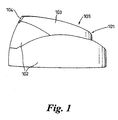
Figure 1 is a diagrammatic illustration showing a side view of a spray-through cap nozzle arrangement according to the present invention; -
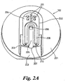
Figure 2A is a diagrammatic illustration showing a perspective view of thelower part 102 of the spray-through cap nozzle arrangement shown inFigure 1 ; -
Figure 2B is a further diagrammatic illustration showing a perspective view of thelower part 102 of the spray-through cap nozzle arrangement shown inFigure 1 ; -
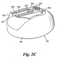
Figure 2C is a line diagram showing the perspective view of thelower part 102 of the spray-through cap nozzle arrangement shown inFigure 2B ; -
Figure 2D is a further diagrammatic illustration showing a perspective view of thelower part 102 of the spray-through cap nozzle arrangement shown inFigure 1 ; -
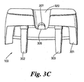
Figure 3A is diagrammatic illustration showing a perspective view of theupper part 103 of the nozzle arrangement shown inFigure 1 ; -
Figure 3B is a diagrammatic illustration showing a perspective view of theupper part 103 of the nozzle arrangement shown inFigure 1 ; -
Figure 3C is an end view of theupper part 103 of the nozzle arrangement shown inFigure 1 ; - In the following description of the figures, like reference numerals are used to denote like parts in different figures, where appropriate.
- Referring to
Figure 1 , a two-part spray-throughcap nozzle arrangement 101 is shown which is adapted to be fitted to the end of a standard cylindrical aerosol canister (not shown). The spray-throughcap nozzle arrangement 101 has alower part 102 and anupper part 103. Anoutlet 104 is formed at the edge of the interface between thelower part 102 and theupper part 103. - To actuate the release of fluid from the outlet valve of the aerosol canister (not shown) and thereby cause fluid to be dispensed through the nozzle arrangement, the
upper part 103 is pressed downwards in the direction ofarrow 105 by an operator. This causes thelower part 102 of the nozzle arrangement to engage and open the valve, as discussed further below in reference toFigures 2A through to 2D. - Referring to
Figures 2A ,2B ,2C and2D , thelower part 102 has circular shapedbase 201 which is configured to be fitted to the end of the standard cylindrical aerosol canister (not shown). Thelower part 102 additionally comprises a centrally positionedactuator portion 202, which is connected to thebase 201 by aconnection portion 203. Theconnection portion 203 is resiliently deformable so as to permit theactuator portion 202 to be pressed downwards relative to thebase 201 and subsequently spring back to its initial position when the downward pressure applied by the operator is released. The lower surface ofactuator portion 202 releasably engages with the outlet valve of the aerosol canister when theactuator portion 202 is pressed downwards in the direction of arrow 105 (as shown inFigure 1 ). Depressing the actuator portion in this manner causes the valve to open and permits the fluid present in the container to be released through thenozzle arrangement 101. - The upper surface of the
actuator portion 202 forms theabutment surface 204 of the lower part. Formed on theabutment surface 204 is agroove 205, which extends from aninlet opening 206 to the edge of theabutment surface 207. Theinlet opening 206 is aligned with the top of the outlet valve of the aerosol canister and forms the inlet of thenozzle arrangement 101 through which fluid released from the aerosol canister accesses thenozzle arrangement 101 during use. As stated above, the lower surface of theactuator part 203 is configured to engage the outlet valve of an aerosol canister and this means that the volume of the inlet is minimal (i.e. there is no significant downwardly extending channel through in which fluid may remain once the actuation of the release of fluid from the outlet valve of the canister ceases). Thegroove 205 forms a wall of the body, which defines an internal surface of the fluid flow passageway and the end of the groove at theedge 207 forms part of theoutlet 104 of thenozzle arrangement 101. Also present on theabutment surface 204 is a horseshoe-shapedrecess 208, which encircles theinlet opening 206 and thegroove 205. This horseshoe-shaped recess forms part of a horseshoe shaped seal in thenozzle arrangement 101, as explained further below in reference toFigure 3A . At the two ends of thehorseshoe shape recess 208 are twoholes Alignment projections 211 are also formed on theabutment surface 204 of thelower part 102. The significance of the twoholes alignment projections 211 will be explained further below in reference toFigures 3A ,3B and3C . - The
upper part 103 of thenozzle arrangement 101 is shown in more detail inFigures 3A ,3B and3C . Referring toFigure 3A , theupper part 103 has anabutment surface 305, which contacts theabutment surface 204 of thelower part 102 to form thefinal nozzle arrangement 101. To enable theupper part 103 to align with thelower part 102 so that theabutment surface 305 abuts theabutment surface 204, theupper part 103 is provided with awall 301, which is configured to fit around the edge of theactuator part 202 of thelower part 103. The appropriate alignment is further assisted by theprotrusion rods holes holes 304 of theupper part 103 receive theprotrusions 211 provided on theabutment surface 204. - The
abutment surface 305 of theupper part 103 is provided with aridge 306, which is resiliently biased in the configuration shown inFigures 3A ,3B and3C . The thickness of the ridge, and hence its resilience, varies along its length. The thickness is highest at theend 330 and gradually tapers towards theend 331. Referring toFigures 3B and3C it can be seen that theridge protrusion 306 is provided a further protrudingridge 307 on the upper surface thereof. Theridge 307, although not preferred (the resilience of the ridge is preferably uniform across its width), can assist in providing the necessary resilience to theridge protrusion 306. - The
upper part 103 is formed from a resiliently deformable plastic material and theridge 306 forms the resiliently deformable wall of the fluid flow passageway when the upper and lower parts are brought together to form thenozzle arrangement 101. In this regard, it is apparent that theridge protrusion 306 is shaped to fit tightly into thegroove 205 of thelower part 102 so that their respective surfaces are in tight contact when the upper and lower parts are fitted together to form thenozzle arrangement 101. This is the initial resiliently biased configuration of the resiliently deformable wall. Theridge protrusion 306 resides along the entire length of thegroove 205 so that the entire length of the passageway thus formed is effectively closed. However, when the release of the contents of the aerosol canister is actuated, the pressure with which the contents access thenozzle arrangement 101 through theinlet 206 causes the wall of the internal passageway formed by the resilientlydeformable ridge protrusion 306 to deform upwards and away from the surface of thegroove 205, thereby opening the internal passageway and enabling the contents of the aerosol canister to flow through and be ejected through theoutlet 104. In practice it is preferable that the ridge protrusion only deforms to approximately one third of the height of thechannel 320 formed on the upper surface of thesecond part 103. This is to keep the height of the vertical channel between the top of the passageway and the top of the outlet valve (positioned directly below the aperture of the lower part 102) to a minimum and hence reduce the amount of product that may be retained in this vertical channel after use. - When the desired quantity of product has been dispensed through the
nozzle arrangement 101, the actuation of the release of the contents is stopped by releasing the actuator portion and the resiliently deformable ridge protrusion then returns to its initial resiliently biased configuration in which its surface contacts the surface of thegroove 205. In doing so, the resilientlydeformable ridge 306 forces any fluid remaining within the fluid flow passageway to flow out of theoutlet 104. The flow of fluid out of the outlet is further enhanced by the greater resilience of the ridge at itsend 330 when compared with its end 331 (due to its greater thickness atend 330 and gradually tapering towards end 331). This causes the ridge to preferentially revert to its initial resiliently biased configuration near to the inlet so that any fluid remaining at the inlet end is displaced towards the outlet in a continuous flow-like motion. - In an alternative embodiment, the
ridge protrusion 306 is provided with a circular protrusion which, when the abutment surfaces 202 and 305 are brought into contact, is received within the inlet opening 206 to form a plug to prevent any residue building up in the inlet. - To prevent any of the contents of the internal passageway from leaking and seeping between the abutment surfaces 202 and 305 during use, a horseshoe-shaped protrusion is provided on the
abutment surface 305 which, when the abutment surfaces 202 and 305 are brought together, is received within the horseshoe-shapedrecess 208 to form a seal which encircles the inlet and internal passageway of thenozzle arrangement 101. In an alternative embodiment, the seal may also extend across the internal passageway (i.e. thegroove 205 may be provided with a recess extending across it width which receives a corresponding protrusion on theridge protrusion 306, or vice versa) to provide an airtight seal when thenozzle arrangement 101 is not in use. The protrusion could be configured to snap-fit into the corresponding recess to form the seal. This may occur due to the elastic force with which the resiliently deformable ridge returns to its original position after use, or alternatively, an operator may have to press the protrusion into the recess. - It shall be appreciated that the description of the embodiments of the invention described in reference to the figures is intended to be by way of example only and should not construed as limiting the scope of the invention, which is defined in the appended claims.
Claims (26)
- A nozzle arrangement (101) adapted to be fitted to a pressurised vessel or container and to permit fluid present in said vessel or container to be dispensed through it under pressure, said nozzle arrangement having a body (102, 103) which defines an inlet (206), an outlet (104), and an internal fluid flow passageway through which fluid can flow from said inlet to said outlet, said body comprising actuator means (103, 202) which is adapted, upon operation, to engage and open an outlet valve of the pressurised vessel or container to which the arrangement is attached and thereby enable fluid present in the pressurised vessel or container to be released into the nozzle arrangement,
the body of the nozzle arrangement comprising a resiliently deformable wall member (306) which defines the entire length or substantially the entire length of the fluid flow passageway, said resiliently deformable wall being configured such that, when fluid is caused to flow through the nozzle arrangement in response to the operation of said actuator means, said wall undergoes a resilient deformation from an initial resiliently-biased configuration in which said passageway is closed to a distended configuration whereby fluid can flow through said passageway and be dispensed through the outlet, said wall being further configured to revert to the initial resiliently-biased configuration when the operation of the actuator means has ceased and thereby cause any fluid remaining in the entire length, or substantially the entire length, of the passageway to be expelled; characterised in that the body of the nozzle arrangement is formed of two interconnected parts (102, 103), each of said parts having respective abutment surfaces (204, 305) which are contacted together, wherein portions (205, 306) of said abutment surfaces form the walls of the body defining said internal fluid flow passageway and at least one of said portions of said abutment surfaces forms said resiliently deformable wall member (306). - A nozzle arrangement according to claim 1, wherein the outlet (104) is defined, at least in part, by a resiliently deformable wall (306) of the body, which is configured such that, when fluid is caused to flow through the nozzle arrangement in response to the operation of said actuator means (103, 202), said wall undergoes a resilient deformation from an initial resiliently-biased configuration in which the outlet is closed to a distended configuration whereby fluid can flow through said outlet, said wall being further configured to revert to the initial resiliently-biased configuration when the operation of the actuator means has ceased and thereby cause any fluid remaining in said outlet to be expelled.
- A nozzle arrangement according to claim 2, wherein the outlet (104) is an open end of said passageway and the resiliently deformable wall (306) which defines the outlet is the end of the resiliently deformable wall which defines said portion of the fluid flow passageway.
- A nozzle arrangement according to any preceding claim, wherein the resilience of the resiliently deformable wall (306) is uniform along its length.
- A nozzle arrangement according to any one of claims 1 to 4, wherein the resiliently deformable wall (306) which defines an internal surface of the fluid flow passageway is adapted such that, when the operation of the actuator (103, 202) has ceased and the resiliently deformable wall reverts to the initial resiliently-biased configuration, any fluid remaining in the passageway is expelled through the outlet (104).
- A nozzle arrangement according to claim 5, wherein the resilience of said resiliently deformable wall (306) varies along its length.
- A nozzle arrangement according to claims 5 or 6, wherein the resilience or elasticity of the resiliently deformable wall (306) is greater at locations (330) disposed from the outlet (104) than at locations (331) proximate to said outlet so that, when the operation of the actuator has ceased, the resiliently deformable wall elastically recoils to the collapsed configuration preferentially at positions further way from the outlet so as to cause any fluid remaining in said portion of the internal passageway to flow towards, and be expelled though, the outlet.
- A nozzle arrangement according to claim 7, wherein in the resiliently deformable wall (306) defines an internal surface which extends for all, or substantially all, of the length of the fluid flow passageway, and the resilience of the resiliently deformable wall is greater at the inlet end of the passageway (330) than at positions (331) proximate to said outlet (104), so that, when the operation of the actuator is ceased, the resiliently deformable wall reverts to the initial resiliently-biased configuration preferentially at the inlet so as to cause any fluid remaining in said passageway to flow towards, and be expelled though, the outlet.
- A nozzle arrangement according to claims 7 or 8, wherein the resilience or elasticity of said resilient deformable wall (306) increases proportionally with increasing distance from the outlet (104).
- A nozzle arrangement according to any preceding claim, wherein two or more walls (205, 306) of the body define the internal fluid flow passageway, at least one of which (306) is resiliently deformable and, in the initial resiliently-biased configuration, is resiliently biased against the opposing walls to define a closed passageway.
- A nozzle arrangement according to claim 10, wherein the internal fluid flow passageway is defined by two walls of the body (205, 306), at least one of said walls being resiliently deformable and providing an internal surface of the passageway which is resiliently biased against the surface formed by the opposing wall (205) in the initial resiliently-biased configuration so as to define a closed passageway.
- A nozzle arrangement according to claim 11, wherein only one of said walls (306) is resiliently deformable and is resiliently biased to abut the opposing wall (205) in the resiliently biased configuration.
- A nozzle arrangement according to claim 1, wherein a first of said abutment surfaces (204) comprises a groove (205) formed in its abutment surface, which extends from an inlet (206) defined by the body to an edge of the abutment surface, said groove forming a first wall of the fluid flow passageway and bering adapted to receive a corresponding resiliently deformable ridge member (306) formed on the abutment surface of the second of abutment surfaces (305), said ridge being resiliently biased against the surface of said groove when the two abutment surfaces are contacted together to form said initial resiliently biased configuration, said ridge (306) being further configured to deform away from said groove (205) to a distended configuration whereby an open passageway is defined when the actuation means is operated and fluid is caused to flow through the arrangement under pressure.
- A nozzle arrangement according to claim 6, wherein the terminus of the fluid flow passageway at the edge of abutment surfaces (204, 305) defines the outlet (104).
- A nozzle arrangement according to any one of claims 1 to 14, wherein said two parts (102, 103) are releasably connected together.
- A nozzle arrangement according to any one of claims 1 to 14, wherein said two parts (102, 103) are permanently connected together.
- A nozzle arrangement according to any one of claims 1 to 16, wherein said parts (102, 103) are made from the same material.
- A nozzle arrangement according to claim 17, wherein said parts (102, 103) are made from a rigid/flexible plastic material.
- A nozzle arrangement according to any one of claims 1 to 16, wherein one of said parts (102) is made from a rigid plastics material and the other of said parts (103) is made from a resiliently deformable material.
- A nozzle arrangement according to any one of claims 1 to 19, wherein a sealing means (208) is disposed between said abutment surfaces (204, 305) to prevent any fluid that leaks from said internal fluid flow passageway from seeping out of the nozzle arrangement between the two opposing abutment surfaces.
- A nozzle arrangement according to any one of the preceding claims, wherein a sealing means is disposed in said fluid flow passageway to provide a substantially airtight seal.
- A nozzle arrangement according to claim 21, wherein said seal comprises a groove on said resiliently deformable wall (306) and extending across the width of the internal fluid flow passageway, said groove being adapted to receive, and form a sealing engagement with, a ridge member formed on an opposing wall when said resiliently deformable wall is in its initial resiliently biased configuration.
- A nozzle arrangement according to claim 21, wherein said seal comprises a ridge member disposed on said resiliently deformable wall (306) and extending across the width of the internal fluid flow passageway, said ridge member being adapted to be received with, and form a sealing engagement with, a groove member formed on an opposing wall when said resiliently deformable wall is in its initial resiliently biased configuration.
- A nozzle arrangement according to any one of claims 21 to 23, wherein said seal is disposed proximate to said outlet (104).
- A nozzle arrangement according to any preceding claim, wherein the nozzle arrangement (101) is configured such that the inlet (206) through which fluid accesses the fluid flow passageway during use is disposed directly adjacent to the outlet valve of the pressurised fluid filled vessel or container to which it is adapted to be attached so that fluid dispensed through the outlet valve flows a minimal distance before entering the fluid flow passageway.
- A pressurised fluid-filled vessel or container comprising an outlet valve and a nozzle arrangement (101) as defined in any one of claims 1 to 25 fitted thereto such that fluid ejected through said outlet valve during use is caused to flow through said nozzle arrangement.
Applications Claiming Priority (13)
| Application Number | Priority Date | Filing Date | Title |
|---|---|---|---|
| GB0219641 | 2002-08-23 | ||
| GB0219641A GB0219641D0 (en) | 2002-08-23 | 2002-08-23 | Outlet device for a container |
| GB0226867 | 2002-11-19 | ||
| GB0226867A GB0226867D0 (en) | 2002-08-23 | 2002-11-19 | Outlet device for a container |
| GB0303698A GB0303698D0 (en) | 2002-08-23 | 2003-02-18 | Outlet device for a container |
| GB0303698 | 2003-02-18 | ||
| GB0305597 | 2003-03-12 | ||
| GB0305597A GB0305597D0 (en) | 2002-08-23 | 2003-03-12 | Outlet device for a container |
| GB0308909 | 2003-04-17 | ||
| GB0308909A GB0308909D0 (en) | 2003-04-17 | 2003-04-17 | Outlet device for a container |
| GB0310244 | 2003-05-03 | ||
| GB0310244A GB0310244D0 (en) | 2003-05-03 | 2003-05-03 | Outlet device for a container |
| PCT/GB2003/003762 WO2004018111A1 (en) | 2002-08-23 | 2003-08-22 | Outlet device for a container or vessel |
Publications (2)
| Publication Number | Publication Date |
|---|---|
| EP1590096A1 EP1590096A1 (en) | 2005-11-02 |
| EP1590096B1 true EP1590096B1 (en) | 2008-11-05 |
Family
ID=31950913
Family Applications (1)
| Application Number | Title | Priority Date | Filing Date |
|---|---|---|---|
| EP03750879A Expired - Lifetime EP1590096B1 (en) | 2002-08-23 | 2003-08-22 | Outlet device for a container or vessel |
Country Status (11)
| Country | Link |
|---|---|
| US (1) | US7651013B2 (en) |
| EP (1) | EP1590096B1 (en) |
| JP (1) | JP2005536346A (en) |
| CN (1) | CN100342981C (en) |
| AT (1) | ATE413232T1 (en) |
| AU (1) | AU2003269097B2 (en) |
| BR (1) | BR0313673A (en) |
| CA (1) | CA2496019A1 (en) |
| DE (1) | DE60324599D1 (en) |
| MX (1) | MXPA05002154A (en) |
| WO (1) | WO2004018111A1 (en) |
Families Citing this family (9)
| Publication number | Priority date | Publication date | Assignee | Title |
|---|---|---|---|---|
| WO2006013353A1 (en) * | 2004-08-03 | 2006-02-09 | Incro Limited | Dispenser for aerosol foams and the like, having a post-expansion chamber |
| DE102006012302A1 (en) * | 2006-03-15 | 2007-09-27 | Seaquist Perfect Dispensing Gmbh | dispenser |
| DE102007051982A1 (en) * | 2007-08-29 | 2009-03-05 | Seaquist Perfect Dispensing Gmbh | dispenser |
| DE102007051980A1 (en) * | 2007-08-29 | 2009-03-05 | Seaquist Perfect Dispensing Gmbh | dispenser |
| US8123082B2 (en) * | 2008-01-22 | 2012-02-28 | McNeil-AB | Hand-held dispensing device |
| FR2933082B1 (en) * | 2008-06-27 | 2012-12-28 | Seaquist Perfect Dispensing Sas | HEAD OF DISTRIBUTION OF FLUID PRODUCT |
| GB201205116D0 (en) | 2012-03-22 | 2012-05-09 | Laidler Keith | Anti post foam device |
| ES2885528T3 (en) | 2015-04-06 | 2021-12-14 | Johnson & Son Inc S C | Dispensing systems |
| CN111956071A (en) * | 2019-05-20 | 2020-11-20 | 新玛德制造厂有限公司 | Improved coffee brewing device |
Family Cites Families (13)
| Publication number | Priority date | Publication date | Assignee | Title |
|---|---|---|---|---|
| US3991916A (en) * | 1974-07-01 | 1976-11-16 | Bon F Del | Automatic closure device for the discharge of a foam product from a pressurized container |
| US4646781A (en) * | 1985-05-07 | 1987-03-03 | Pacesetter Infusion, Ltd. | Diaphragm valve for medication infusion pump |
| ES2050976T3 (en) * | 1989-07-25 | 1994-06-01 | Oreal | DISTRIBUTION SET OF AT LEAST ONE FLUID PRODUCT, MAINLY COSMETIC OR PHARMACEUTICAL. |
| US5205443A (en) * | 1990-01-12 | 1993-04-27 | Takasago Perfumery Co., Ltd. | Actuator for liquid ejection |
| FR2679620B1 (en) * | 1991-07-25 | 1993-10-29 | Oreal | ADJUSTABLE VALVE. |
| FR2693991B1 (en) * | 1992-07-21 | 1994-11-25 | Oreal | Distribution assembly for at least one liquid or pasty product, comprising a closure system without air intake and preservation method using said assembly. |
| FR2704458B1 (en) * | 1993-04-28 | 1995-07-21 | Oreal | Product distribution set. |
| US5613517A (en) * | 1994-10-24 | 1997-03-25 | Reseal International Limited Partnership | Sheath valve |
| EP0747292B1 (en) * | 1994-12-22 | 2002-03-27 | Pentel Kabushiki Kaisha | Discharge container |
| ES2155206T3 (en) | 1996-02-28 | 2001-05-01 | Incro Ltd | SPRAY APPLIANCE AND NOZZLE DEVICES. |
| FR2756899B1 (en) * | 1996-12-06 | 1999-01-08 | Oreal | VALVE WITH INSTANT CLOSING AND PRODUCT DISPENSER COMPRISING A PUMP EQUIPPED WITH THIS VALVE |
| WO2001025116A1 (en) * | 1999-10-01 | 2001-04-12 | Berry Plastics Corporation | Dispenser outlet closure for pressurized container |
| GB0011218D0 (en) | 2000-05-10 | 2000-06-28 | Incro Ltd | Improvements in or relating to a nozzle arrangement |
-
2003
- 2003-08-22 MX MXPA05002154A patent/MXPA05002154A/en active IP Right Grant
- 2003-08-22 EP EP03750879A patent/EP1590096B1/en not_active Expired - Lifetime
- 2003-08-22 AT AT03750879T patent/ATE413232T1/en not_active IP Right Cessation
- 2003-08-22 CA CA002496019A patent/CA2496019A1/en not_active Abandoned
- 2003-08-22 JP JP2005501221A patent/JP2005536346A/en active Pending
- 2003-08-22 DE DE60324599T patent/DE60324599D1/en not_active Expired - Lifetime
- 2003-08-22 US US10/525,200 patent/US7651013B2/en not_active Expired - Fee Related
- 2003-08-22 CN CNB038200228A patent/CN100342981C/en not_active Expired - Fee Related
- 2003-08-22 WO PCT/GB2003/003762 patent/WO2004018111A1/en active Application Filing
- 2003-08-22 AU AU2003269097A patent/AU2003269097B2/en not_active Ceased
- 2003-08-22 BR BR0313673-6A patent/BR0313673A/en active Search and Examination
Also Published As
| Publication number | Publication date |
|---|---|
| JP2005536346A (en) | 2005-12-02 |
| CN1678405A (en) | 2005-10-05 |
| EP1590096A1 (en) | 2005-11-02 |
| MXPA05002154A (en) | 2005-05-23 |
| US20060081658A1 (en) | 2006-04-20 |
| ATE413232T1 (en) | 2008-11-15 |
| AU2003269097B2 (en) | 2008-09-04 |
| CN100342981C (en) | 2007-10-17 |
| DE60324599D1 (en) | 2008-12-18 |
| AU2003269097A1 (en) | 2004-03-11 |
| US7651013B2 (en) | 2010-01-26 |
| CA2496019A1 (en) | 2004-03-04 |
| BR0313673A (en) | 2005-06-21 |
| WO2004018111A1 (en) | 2004-03-04 |
Similar Documents
| Publication | Publication Date | Title |
|---|---|---|
| EP1594619B1 (en) | Spray nozzle | |
| EP1590096B1 (en) | Outlet device for a container or vessel | |
| WO2004080607A1 (en) | Improvements in or relating to dispenser nozzles | |
| WO1999007614A1 (en) | Container | |
| KR20010072204A (en) | Container valve | |
| ZA200505581B (en) | Dispenser pump |
Legal Events
| Date | Code | Title | Description |
|---|---|---|---|
| PUAI | Public reference made under article 153(3) epc to a published international application that has entered the european phase |
Free format text: ORIGINAL CODE: 0009012 |
|
| 17P | Request for examination filed |
Effective date: 20050127 |
|
| AK | Designated contracting states |
Kind code of ref document: A1 Designated state(s): AT BE BG CH CY CZ DE DK EE ES FI FR GB GR HU IE IT LI LU MC NL PT RO SE SI SK TR |
|
| AX | Request for extension of the european patent |
Extension state: AL LT LV MK |
|
| DAX | Request for extension of the european patent (deleted) | ||
| 17Q | First examination report despatched |
Effective date: 20070824 |
|
| GRAP | Despatch of communication of intention to grant a patent |
Free format text: ORIGINAL CODE: EPIDOSNIGR1 |
|
| GRAS | Grant fee paid |
Free format text: ORIGINAL CODE: EPIDOSNIGR3 |
|
| GRAA | (expected) grant |
Free format text: ORIGINAL CODE: 0009210 |
|
| AK | Designated contracting states |
Kind code of ref document: B1 Designated state(s): AT BE BG CH CY CZ DE DK EE ES FI FR GB GR HU IE IT LI LU MC NL PT RO SE SI SK TR |
|
| REG | Reference to a national code |
Ref country code: GB Ref legal event code: FG4D |
|
| REG | Reference to a national code |
Ref country code: CH Ref legal event code: EP |
|
| REG | Reference to a national code |
Ref country code: IE Ref legal event code: FG4D |
|
| REF | Corresponds to: |
Ref document number: 60324599 Country of ref document: DE Date of ref document: 20081218 Kind code of ref document: P |
|
| NLV1 | Nl: lapsed or annulled due to failure to fulfill the requirements of art. 29p and 29m of the patents act | ||
| PG25 | Lapsed in a contracting state [announced via postgrant information from national office to epo] |
Ref country code: ES Free format text: LAPSE BECAUSE OF FAILURE TO SUBMIT A TRANSLATION OF THE DESCRIPTION OR TO PAY THE FEE WITHIN THE PRESCRIBED TIME-LIMIT Effective date: 20090216 Ref country code: AT Free format text: LAPSE BECAUSE OF FAILURE TO SUBMIT A TRANSLATION OF THE DESCRIPTION OR TO PAY THE FEE WITHIN THE PRESCRIBED TIME-LIMIT Effective date: 20081105 |
|
| PG25 | Lapsed in a contracting state [announced via postgrant information from national office to epo] |
Ref country code: FI Free format text: LAPSE BECAUSE OF FAILURE TO SUBMIT A TRANSLATION OF THE DESCRIPTION OR TO PAY THE FEE WITHIN THE PRESCRIBED TIME-LIMIT Effective date: 20081105 Ref country code: SI Free format text: LAPSE BECAUSE OF FAILURE TO SUBMIT A TRANSLATION OF THE DESCRIPTION OR TO PAY THE FEE WITHIN THE PRESCRIBED TIME-LIMIT Effective date: 20081105 Ref country code: NL Free format text: LAPSE BECAUSE OF FAILURE TO SUBMIT A TRANSLATION OF THE DESCRIPTION OR TO PAY THE FEE WITHIN THE PRESCRIBED TIME-LIMIT Effective date: 20081105 |
|
| PG25 | Lapsed in a contracting state [announced via postgrant information from national office to epo] |
Ref country code: EE Free format text: LAPSE BECAUSE OF FAILURE TO SUBMIT A TRANSLATION OF THE DESCRIPTION OR TO PAY THE FEE WITHIN THE PRESCRIBED TIME-LIMIT Effective date: 20081105 Ref country code: RO Free format text: LAPSE BECAUSE OF FAILURE TO SUBMIT A TRANSLATION OF THE DESCRIPTION OR TO PAY THE FEE WITHIN THE PRESCRIBED TIME-LIMIT Effective date: 20081105 Ref country code: DK Free format text: LAPSE BECAUSE OF FAILURE TO SUBMIT A TRANSLATION OF THE DESCRIPTION OR TO PAY THE FEE WITHIN THE PRESCRIBED TIME-LIMIT Effective date: 20081105 Ref country code: BE Free format text: LAPSE BECAUSE OF FAILURE TO SUBMIT A TRANSLATION OF THE DESCRIPTION OR TO PAY THE FEE WITHIN THE PRESCRIBED TIME-LIMIT Effective date: 20081105 Ref country code: BG Free format text: LAPSE BECAUSE OF FAILURE TO SUBMIT A TRANSLATION OF THE DESCRIPTION OR TO PAY THE FEE WITHIN THE PRESCRIBED TIME-LIMIT Effective date: 20090205 |
|
| PG25 | Lapsed in a contracting state [announced via postgrant information from national office to epo] |
Ref country code: SE Free format text: LAPSE BECAUSE OF FAILURE TO SUBMIT A TRANSLATION OF THE DESCRIPTION OR TO PAY THE FEE WITHIN THE PRESCRIBED TIME-LIMIT Effective date: 20090205 Ref country code: CZ Free format text: LAPSE BECAUSE OF FAILURE TO SUBMIT A TRANSLATION OF THE DESCRIPTION OR TO PAY THE FEE WITHIN THE PRESCRIBED TIME-LIMIT Effective date: 20081105 Ref country code: PT Free format text: LAPSE BECAUSE OF FAILURE TO SUBMIT A TRANSLATION OF THE DESCRIPTION OR TO PAY THE FEE WITHIN THE PRESCRIBED TIME-LIMIT Effective date: 20090406 |
|
| PLBE | No opposition filed within time limit |
Free format text: ORIGINAL CODE: 0009261 |
|
| STAA | Information on the status of an ep patent application or granted ep patent |
Free format text: STATUS: NO OPPOSITION FILED WITHIN TIME LIMIT |
|
| PG25 | Lapsed in a contracting state [announced via postgrant information from national office to epo] |
Ref country code: SK Free format text: LAPSE BECAUSE OF FAILURE TO SUBMIT A TRANSLATION OF THE DESCRIPTION OR TO PAY THE FEE WITHIN THE PRESCRIBED TIME-LIMIT Effective date: 20081105 |
|
| 26N | No opposition filed |
Effective date: 20090806 |
|
| PGFP | Annual fee paid to national office [announced via postgrant information from national office to epo] |
Ref country code: GB Payment date: 20090821 Year of fee payment: 7 |
|
| PGFP | Annual fee paid to national office [announced via postgrant information from national office to epo] |
Ref country code: DE Payment date: 20091027 Year of fee payment: 7 |
|
| PG25 | Lapsed in a contracting state [announced via postgrant information from national office to epo] |
Ref country code: MC Free format text: LAPSE BECAUSE OF NON-PAYMENT OF DUE FEES Effective date: 20090831 |
|
| REG | Reference to a national code |
Ref country code: CH Ref legal event code: PL |
|
| PG25 | Lapsed in a contracting state [announced via postgrant information from national office to epo] |
Ref country code: LI Free format text: LAPSE BECAUSE OF NON-PAYMENT OF DUE FEES Effective date: 20090831 Ref country code: CH Free format text: LAPSE BECAUSE OF NON-PAYMENT OF DUE FEES Effective date: 20090831 |
|
| PG25 | Lapsed in a contracting state [announced via postgrant information from national office to epo] |
Ref country code: IE Free format text: LAPSE BECAUSE OF NON-PAYMENT OF DUE FEES Effective date: 20090822 |
|
| PG25 | Lapsed in a contracting state [announced via postgrant information from national office to epo] |
Ref country code: GR Free format text: LAPSE BECAUSE OF FAILURE TO SUBMIT A TRANSLATION OF THE DESCRIPTION OR TO PAY THE FEE WITHIN THE PRESCRIBED TIME-LIMIT Effective date: 20090206 |
|
| PG25 | Lapsed in a contracting state [announced via postgrant information from national office to epo] |
Ref country code: IT Free format text: LAPSE BECAUSE OF NON-PAYMENT OF DUE FEES Effective date: 20090822 |
|
| GBPC | Gb: european patent ceased through non-payment of renewal fee |
Effective date: 20100822 |
|
| PG25 | Lapsed in a contracting state [announced via postgrant information from national office to epo] |
Ref country code: LU Free format text: LAPSE BECAUSE OF NON-PAYMENT OF DUE FEES Effective date: 20090822 |
|
| REG | Reference to a national code |
Ref country code: FR Ref legal event code: ST Effective date: 20110502 |
|
| REG | Reference to a national code |
Ref country code: DE Ref legal event code: R119 Ref document number: 60324599 Country of ref document: DE Effective date: 20110301 |
|
| PG25 | Lapsed in a contracting state [announced via postgrant information from national office to epo] |
Ref country code: HU Free format text: LAPSE BECAUSE OF FAILURE TO SUBMIT A TRANSLATION OF THE DESCRIPTION OR TO PAY THE FEE WITHIN THE PRESCRIBED TIME-LIMIT Effective date: 20090506 |
|
| PG25 | Lapsed in a contracting state [announced via postgrant information from national office to epo] |
Ref country code: FR Free format text: LAPSE BECAUSE OF NON-PAYMENT OF DUE FEES Effective date: 20100831 Ref country code: DE Free format text: LAPSE BECAUSE OF NON-PAYMENT OF DUE FEES Effective date: 20110301 |
|
| PGFP | Annual fee paid to national office [announced via postgrant information from national office to epo] |
Ref country code: IT Payment date: 20090820 Year of fee payment: 7 |
|
| PGRI | Patent reinstated in contracting state [announced from national office to epo] |
Ref country code: IT Effective date: 20110616 |
|
| PG25 | Lapsed in a contracting state [announced via postgrant information from national office to epo] |
Ref country code: TR Free format text: LAPSE BECAUSE OF FAILURE TO SUBMIT A TRANSLATION OF THE DESCRIPTION OR TO PAY THE FEE WITHIN THE PRESCRIBED TIME-LIMIT Effective date: 20081105 Ref country code: GB Free format text: LAPSE BECAUSE OF NON-PAYMENT OF DUE FEES Effective date: 20100822 |
|
| PG25 | Lapsed in a contracting state [announced via postgrant information from national office to epo] |
Ref country code: CY Free format text: LAPSE BECAUSE OF FAILURE TO SUBMIT A TRANSLATION OF THE DESCRIPTION OR TO PAY THE FEE WITHIN THE PRESCRIBED TIME-LIMIT Effective date: 20081105 |
|
| PGFP | Annual fee paid to national office [announced via postgrant information from national office to epo] |
Ref country code: FR Payment date: 20090911 Year of fee payment: 7 |
|
| PGRI | Patent reinstated in contracting state [announced from national office to epo] |
Ref country code: IT Effective date: 20110616 |