EP1589683A1 - Multi-carrier communication system and reception device thereof - Google Patents
Multi-carrier communication system and reception device thereof Download PDFInfo
- Publication number
- EP1589683A1 EP1589683A1 EP03815589A EP03815589A EP1589683A1 EP 1589683 A1 EP1589683 A1 EP 1589683A1 EP 03815589 A EP03815589 A EP 03815589A EP 03815589 A EP03815589 A EP 03815589A EP 1589683 A1 EP1589683 A1 EP 1589683A1
- Authority
- EP
- European Patent Office
- Prior art keywords
- sub
- channel
- soft decision
- channels
- receive
- Prior art date
- Legal status (The legal status is an assumption and is not a legal conclusion. Google has not performed a legal analysis and makes no representation as to the accuracy of the status listed.)
- Withdrawn
Links
Images




Classifications
-
- H—ELECTRICITY
- H04—ELECTRIC COMMUNICATION TECHNIQUE
- H04L—TRANSMISSION OF DIGITAL INFORMATION, e.g. TELEGRAPHIC COMMUNICATION
- H04L25/00—Baseband systems
- H04L25/02—Details ; arrangements for supplying electrical power along data transmission lines
- H04L25/03—Shaping networks in transmitter or receiver, e.g. adaptive shaping networks
- H04L25/03006—Arrangements for removing intersymbol interference
-
- H—ELECTRICITY
- H04—ELECTRIC COMMUNICATION TECHNIQUE
- H04L—TRANSMISSION OF DIGITAL INFORMATION, e.g. TELEGRAPHIC COMMUNICATION
- H04L25/00—Baseband systems
- H04L25/02—Details ; arrangements for supplying electrical power along data transmission lines
- H04L25/0202—Channel estimation
- H04L25/0204—Channel estimation of multiple channels
-
- H—ELECTRICITY
- H04—ELECTRIC COMMUNICATION TECHNIQUE
- H04L—TRANSMISSION OF DIGITAL INFORMATION, e.g. TELEGRAPHIC COMMUNICATION
- H04L25/00—Baseband systems
- H04L25/02—Details ; arrangements for supplying electrical power along data transmission lines
- H04L25/06—DC level restoring means; Bias distortion correction ; Decision circuits providing symbol by symbol detection
- H04L25/067—DC level restoring means; Bias distortion correction ; Decision circuits providing symbol by symbol detection providing soft decisions, i.e. decisions together with an estimate of reliability
-
- H—ELECTRICITY
- H04—ELECTRIC COMMUNICATION TECHNIQUE
- H04L—TRANSMISSION OF DIGITAL INFORMATION, e.g. TELEGRAPHIC COMMUNICATION
- H04L27/00—Modulated-carrier systems
- H04L27/26—Systems using multi-frequency codes
- H04L27/2601—Multicarrier modulation systems
- H04L27/2647—Arrangements specific to the receiver only
-
- H—ELECTRICITY
- H04—ELECTRIC COMMUNICATION TECHNIQUE
- H04L—TRANSMISSION OF DIGITAL INFORMATION, e.g. TELEGRAPHIC COMMUNICATION
- H04L5/00—Arrangements affording multiple use of the transmission path
- H04L5/02—Channels characterised by the type of signal
- H04L5/023—Multiplexing of multicarrier modulation signals, e.g. multi-user orthogonal frequency division multiple access [OFDMA]
- H04L5/026—Multiplexing of multicarrier modulation signals, e.g. multi-user orthogonal frequency division multiple access [OFDMA] using code division
-
- H—ELECTRICITY
- H04—ELECTRIC COMMUNICATION TECHNIQUE
- H04L—TRANSMISSION OF DIGITAL INFORMATION, e.g. TELEGRAPHIC COMMUNICATION
- H04L25/00—Baseband systems
- H04L25/02—Details ; arrangements for supplying electrical power along data transmission lines
- H04L25/03—Shaping networks in transmitter or receiver, e.g. adaptive shaping networks
- H04L25/03006—Arrangements for removing intersymbol interference
- H04L2025/0335—Arrangements for removing intersymbol interference characterised by the type of transmission
- H04L2025/03375—Passband transmission
- H04L2025/03414—Multicarrier
-
- H—ELECTRICITY
- H04—ELECTRIC COMMUNICATION TECHNIQUE
- H04L—TRANSMISSION OF DIGITAL INFORMATION, e.g. TELEGRAPHIC COMMUNICATION
- H04L25/00—Baseband systems
- H04L25/02—Details ; arrangements for supplying electrical power along data transmission lines
- H04L25/03—Shaping networks in transmitter or receiver, e.g. adaptive shaping networks
- H04L25/03006—Arrangements for removing intersymbol interference
- H04L2025/03433—Arrangements for removing intersymbol interference characterised by equaliser structure
- H04L2025/03439—Fixed structures
- H04L2025/03522—Frequency domain
-
- H—ELECTRICITY
- H04—ELECTRIC COMMUNICATION TECHNIQUE
- H04L—TRANSMISSION OF DIGITAL INFORMATION, e.g. TELEGRAPHIC COMMUNICATION
- H04L25/00—Baseband systems
- H04L25/02—Details ; arrangements for supplying electrical power along data transmission lines
- H04L25/0202—Channel estimation
- H04L25/0224—Channel estimation using sounding signals
- H04L25/0228—Channel estimation using sounding signals with direct estimation from sounding signals
- H04L25/023—Channel estimation using sounding signals with direct estimation from sounding signals with extension to other symbols
- H04L25/0232—Channel estimation using sounding signals with direct estimation from sounding signals with extension to other symbols by interpolation between sounding signals
Definitions
- the present invention relates to a multi-carrier communication system and a receiver thereof, and more particularly to a multi-carrier communication system using the interference between a target sub-channel and two or more upper and lower sub-channels (ICI) and a receiver thereof.
- ICI upper and lower sub-channels
- the bit error rate (BER) of the multi-carrier communication system in filter bank modulation, DMT modulation and FMT modulation can be improved by using receive signals that include distortion by inter-channel interference (ICI).
- Inter-channel interference occurs by the malfunction of a system in communication systems, such as OFDM - CDMA, or due to an unavoidable environment such as the loss of orthogonality between sub-channels.
- Inter-channel interference which is called the "leak of spectrum energy", at times the cross-talk between sub-channels, is caused by a leak.
- a major advantage of the turbo receiver of the present invention is that the phenomenon of ICI is handled as a zero mean Gaussian distribution random variable (e.g. Gaussian approximation used in the following document 1 below), for which a finite state discrete Markov process model is used. For such an ICI model, simple Gaussian approximation seems to be more practical because of the nature of ICI.
- the turbo receiver of the present invention is based on a maximum posterior probability estimation algorithm. In this turbo receiver, information derived from one sub-channel after non-linear processing refines the estimated maximum posterior probability of the latter channel, and in the same way, the information derived from the other sub-channel refines the estimated maximum probability of the former sub-channel.
- Document 1 K. Sathanathan and C. Tellambura: "Probability of error calculation of OFDM system with frequency offset", IEEE Trans. Commun., Vol. 49, NO. 11, Nov. 2001, pp. 1884 - 1888.
- the selection of a filter set in a multi-carrier communication system for filter bank modulation DMT (Discrete Multi-tone) modulation and FMT (Filtered Multi-tone) modulation, has been executed under the constraint that inter-symbol interference (ISI) and inter-channel interference (ICI) are completely removed.
- ISI inter-symbol interference
- ICI inter-channel interference
- the only method to relax such deterioration of BER is to minimize the frequency offset, and more particularly, to maintain it to be within 1% of the sub-carrier frequency interval.
- This method requires accurate frequency offset estimation, and also if the noise level is high when multi-carrier signals mixed with noise are received, the accuracy of frequency offset estimation is affected. Also according to this method, the Doppler shift is not consistent with respect to the transmission symbols in a high-speed fading channel, and operation becomes inaccurate in a high-speed fading channel which changes depending on the time.
- a target channel the first adjacent sub-channel located below the target sub-channel and the second adjacent sub-channel located above the target sub-channel, are considered.
- Fig. 1 and Fig. 2 show the frequency response of the three channels in the case when the frequency offset is zero (Fig. 1), and in the case when the frequency offset is not zero (Fig. 2).
- the signals of the central frequencies f 1 , f 2 and f 3 corresponding to the first, second and third sub-channels are indicated by the vertical arrows in Fig.
- the sub-channel number 0 (ch0) indicates the target sub-channel
- the sub-channel number -1 (ch-1) is a sub-channel located below the target sub-channel in the frequency scale
- the sub-channel number +1 (ch+1) indicates the sub-channel located above the target sub-channel in the frequency scale.
- the cycle of the DMT symbol is T
- the frequency scale is normalized with a channel interval equal to 1/T. In other words, one unit of the frequency scale is the channel interval.
- Fig. 1 shows, when the frequency offset (normalized by the channel interval) ⁇ is 0, the transfer function of the lower sub-channel and the upper sub-channel, indicated by the solid line A and the dotted line B in Fig.
- Fig. 2 shows the spectrum characteristics of each sub-channel of the DMT system when the frequency offset ⁇ is not zero.
- the spectrum of adjacent channels cross at -3dB, and the first side-lobe is -13dB, which is high.
- the case when the sub-channels which are distant for a 1 or 2 channel interval interfere with each other will be considered below. It is clear that the spectrum of an adjacent sub-channel has a mutual gain which is not zero, which is indicated as ⁇ 0-1 , ⁇ 1-1 , ⁇ 10 , ⁇ -10 , ⁇ 01 and ⁇ -11 .
- the first index of a indicates the interference source sub-channel
- the second index indicates the interference target sub-channel.
- ⁇ -10 indicates the leak transfer coefficient (amplitude) from the lower sub-channel with the sub-channel number -1 to the target channel with the sub-channel number 0.
- ⁇ -11 indicates the leak transfer coefficient (amplitude) from the lower sub-channel with the sub-channel number -1 to the upper sub-channel with the sub-channel number 1
- ⁇ 01 indicates the leak transfer coefficient from the target sub-channel with the sub-channel number 0 to the higher sub-channel with the sub-channel number 1
- ⁇ 0-1 indicates the leak transfer coefficient from the target sub-channel with the sub-channel number 0 to the lower sub-channel with the sub-channel number -1
- ⁇ 10 indicates the leak transfer coefficient from the higher sub-channel with the sub-channel number +1 to the target sub-channel with the sub-channel number 0.
- Fig. 3 is a general model (four sub-channel model) depicting the mutual ICI of four sub-channels in a DMT system having frequency offset.
- the four sub-channel model can improve the total system BER in more cases because of the low roll off spectrum characteristics of DMT.
- 1 1 , 1 2 , 1 3 and 1 4 are the transmitters of the sub-channels ch-1, ch0, ch+1 and ch+2, 2 1 , 2 2 , 2 3 and 2 4 are the receivers of each sub-channel, 3 1 , 3 2 , 3 3 and 3 4 are the transmission lines of each sub-channel.
- 4 ij is a multiplier to multiply the sub-channel signal D i by the leak transfer coefficient (interference coefficient) ⁇ ij of the sub-channel with the number i to the sub-channel with the number j respectively
- 5 1 , 5 2 , 5 3 and 5 4 are the first synthesizing units for synthesizing the cross-talk (ICI) from the adjacent sub-channel to its own sub-channel signal
- 6 1 , 6 2 , 6 3 and 6 4 are the second synthesizing units for synthesizing the cross-talk (ICI) from the sub-channel which is distant from two channel intervals to its own sub-channel signal
- 7 1 , 7 2 , 7 3 and 7 4 are the noise synthesizing units.
- the signals from the lower sub-channel ch-1 leak into the target sub-channel ch0 via the cross-talk coefficient ⁇ -10
- the signals from the upper sub-channel ch+1 leak into the target sub-channel via the cross-talk coefficient ⁇ 10
- the signals from the upper sub-channel ch+2 leak into the target sub-channel ch0 via the cross-talk coefficient ⁇ 20
- the signals from the lower sub-channel ch-2 leak into the target sub-channel via the cross-talk coefficient ⁇ -20 , but description thereof will be omitted since this can be regarded as the same as the leak from the ch+2.
- the sub-channels that cause mutual interference are limited to the upper and lower sub-channels, but the number of sub-channels in the entire communication system is not limited, so the model in Fig. 3 can also be applied to a multi-carrier communication system that has N number of sub-channels, where N is 4 or a greater number.
- interference to each sub-channel is only from the lower two sub-channels and the upper two sub-channels.
- the interference coefficient indicates a chain of coefficients.
- the noise components denoted as n 1 (t), n 2 (t), n 3 (t) and n 4 (t) in Fig. 3 are statistically independent (no correlation) because of the frequency orthogonality between the sub-channels.
- the sub-channels are located in the frequency domain, but this model can be applied not only to a DMT modulation type or a filter bank modulation type system, but also to other systems.
- the dimensions can be expanded to other domains, such as space (space division multiplex axis) and polarity.
- the model in Fig. 3 is beneficial in terms of understanding the physical process which causes ICI.
- the problem of this model lies in accurately deciding the receive signals of each sub-channel and the value of the transmission information symbols (a sign if a binary number).
- DFE decision feedback equalizer
- the present invention is a multi-carrier communication system for transmitting/receiving signals via at least four sub-channels, comprising a transmitter for transmitting data independently via four channels, a receiver comprising a receive unit disposed for each sub-channel for receiving data from a corresponding sub-channel and performing soft decision of the receive data, and means for inputting soft decision target values in the receive units corresponding to sub-channels other than a target sub-channel to a receive unit of the target sub-channel, wherein the receive unit of the target sub-channel adjusts its own soft decision target value using the soft decision target values that are input from the receive units of the other sub-channels, and decides the receive data based on the adjusted soft decision target value.
- the receive unit of the target sub-channel further comprises means for computing a difference between a probability that the data received from the target sub-channel is one value of a binary and a probability that the data is the other value of a binary as the soft decision target value, considering degree of coupling of cross-talk paths, means for adjusting the soft decision target value of the target sub-channel using the soft decision target values that are input from the receive units of the other sub-channels, and a decision unit for deciding the receive data based on adjusted the soft decision target value.
- Fig. 4 is a general block diagram depicting a communication system that demodulates receive data using the interference between a total of two sub-channels, lower and upper, and is a case when the number of sub-channels is three.
- the intent of the present invention is to provide a communication system having at least four sub-channels (four sub-channel model), but a communication system having three sub-channels (three sub-channel model) will be described first to assist in understanding the present invention.
- the communication system in Fig. 4 comprises three transmitters, 21, 22 and 23, for transmitting data independently via the three sub-channels, ch-1, ch0 and ch+1 respectively, many cross-talk paths 31 ij having a coupling coefficient ⁇ ij to the i-th to the j-th sub-channel, three receivers, 40, 50 and 60, which are installed for each sub-channel for receiving data from the corresponding sub-channel and performing the soft decision of the receive data, and means 71 and 72 for inputting the soft decision target value of each receiver to another receiver.
- 32 - 34 and 35 - 37 are synthesizing units for synthesizing ICI signals and noise.
- the receiver 50 of the sub-channel ch0 adjusts its own soft decision target value using the soft decision target values which were input from the receivers 40 and 60 of the lower and upper sub-channels ch-1 and ch+1, and decides "0" or "1" of the receive data based on the soft decision target value.
- the other respective receivers adjust its own soft decision target value using the soft decision target values which were input from the receivers of the lower and upper sub-channels, and decides "0" or "1” of the receiver data based on the soft bit decision target value.
- the value InD 0 to indicate the difference of the posterior possibility, is derived.
- the binary information is transmitted as the signal S* ij (t) via the two adjacent sub-channels.
- the time dependency of S* ij (t) in expressions is omitted.
- S* ij (t) is denoted as S* ij .
- the transmission information symbol D i is statistically independent (no correlation) and is an equally distributed probability variable.
- the signal of the target sub-channel affected by ICI from the lower and upper sub-channels is expressed as the linear coupling of the signals S* -1j and S* 1J transmitted by the upper and lower sub-channels and the target channel signal S* 0j by the cross-talk coefficient ⁇ .
- the index j of S j in the expressions (2) and (3) indicates the signal number, and is determined by pairing the symbols D -1 , D 1 and D 0 in the lower sub-channel, upper sub-channel and target sub-channel.
- the posterior probability to receive the signal S j that is the posterior probability P (S j /y (t)) of the receive signal becoming S j , is given by the following expression.
- P apr (S j ) is a prior probability of the receive signal S j
- P (y(t)/S j ) is a conditional probability, and is a probability where the transmitted sign signal is S j when the receive signal is y(t).
- D 0 +1
- P apr (S j ) is a prior probability (transmission probability) of the information signal S j with the number j in the target sub-channel being transmitted.
- Prior probability P apr (S* ij ) depends on the statistics of the data generation source, and in practical terms it is assumed to be equal to 1 ⁇ 2.
- Probability P (S* ij ) is the posterior probability of the receive signal S* ij , which is different from the prior probability P apr (S* ij ), and can be estimated at the receive side with high reliability, so P (S* ij ) ⁇ P (S* ij /y(t)).
- the decision information of the adjacent channels is used to decide the sign of the transmission information symbol D of a sub-channel.
- ln D -1 and ln D +1 indicate the logarithmic difference of the posterior probability of the information symbol in the lower sub-channel (ch-1) and the upper sub-channel (ch+1) becoming +1 and the posterior probability of that becoming -1. All calculations are in series, so when processing the data of the target sub-channel, the latest posterior probability from the adjacent channels can be used by repeat calculation.
- the algorithm is created such that InD 0 , which is the soft decision target value, is computed by the expressions (27) - (30), then "0" or "1" of the receive symbol of the target sub-channel is decided depending on the positive/negative of the soft decision target value InD 0 .
- Fig. 5 is a block diagram depicting a receiver of a three sub-channel model, that is, a receiver based on the maximum posterior probability using ICI (called a turbo receiver), and shows the configuration of only the receive unit of the target sub-channel, but the receive units of the other sub-channels also have the same configuration.
- This receive unit also has a configuration to execute the above mentioned algorithm.
- the receiver 50 of the target sub-channel further comprises a correlation unit (can be a match fill) 51, another channel decision result operating unit 52, first and second non-linear units 53 and 54, and symbol decision unit 55.
- a correlation unit can be a match fill
- another channel decision result operating unit 52 another channel decision result operating unit 52
- first and second non-linear units 53 and 54 second non-linear units 53 and 54
- symbol decision unit 55 symbol decision unit 55.
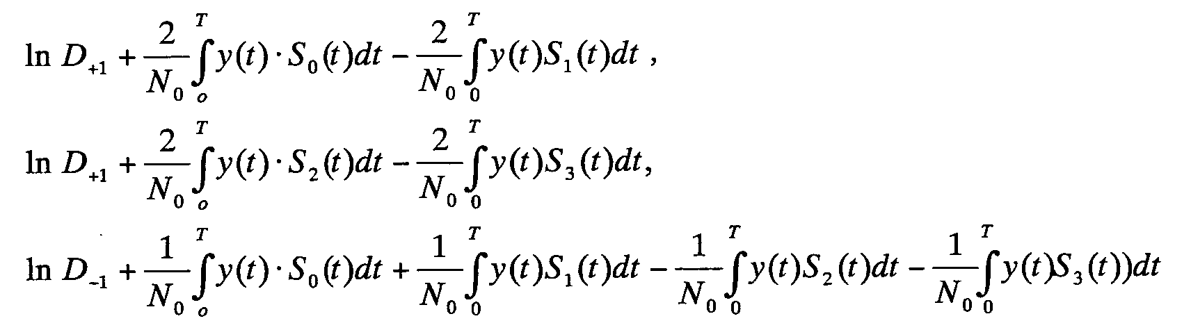
- the multiplier 51a and integrator 51b of the correlation unit 51 is a unit for computing of the decision expressions (28) - (30), the multiplier 51c and integrator 51d are units for computing the multiplier 51e and integrator 51f are units for computing and the multiplier 51g and integrator 51h are units for computing
- the addition unit 51i adds the integration output of the integrators 51b and 51d, subtractor 51j subtracts the integration outputs of the integrators 51b and 51d, the addition unit 51k adds the integration outputs of the integrators 51f and 51h, and the subtractor 51m subtracts the integration outputs of the integrators 51f and 51h.
- the addition unit 51n adds the outputs of the addition units 51i and 51k, and outputs the first term of the right side member of the expression (28), that is
- the subtraction unit 51 p subtracts the outputs of the addition units 51i and 51k, and outputs
- the division units 51q and 51r divide the input signal 1 ⁇ 2, and output the result.
- the other channel decision result operating unit 52 comprises the adders 52a - 52c, which compute the following respectively.
- the first non-linear unit 53 is a unit for computing ln cosh of the second - fifth terms of the right side member of the expression (28), and comprises the first and second non-linear sections 53a and 53b.
- the addition units 71a and 71b of the first non-linear section 53a compute the content of ⁇ ⁇ of the second and third terms of the right side member of the expression (28) respectively.
- the (E 0 - E 1 )/N 0 ⁇ E 1 .
- ln cosh computing units 71c and 71d compute the second and third terms of the right side member of the expression (28) respectively, and the subtractor 71e subtracts the computing result of the ln cosh computing unit 71d from the computing result of the ln cosh computing unit 71c.
- the addition units 71a' and 71b' of the second non-linear unit 53b compute the content of ⁇ ⁇ of the fourth and fifth terms of the right side member of the expression (28) respectively.
- the (E 2 - E 3 )/N 0 ⁇ E 2 ln cosh computing units 71c' and 71d' compute the fourth and fifth terms of the right side member of the expression (28) respectively, and the subtractor 71e' subtracts the computing result of the ln cosh computing unit 71d' from the computing result of the ln cosh computing unit 71c', and outputs the result.
- the addition unit 53c synthesizes the outputs of the adders 71e and 71e' and the division unit 53d divides the synthesized signal by 1 ⁇ 2, and outputs the computing results of the second - fifth terms of the expression (28).
- the second non-linear unit 54 is a unit for computing the first - third terms of the right side member of the expressions (29) and (30).
- the addition units 54a and 54b compute the first term of the right side member of the expressions (29) and (30) respectively
- the addition units 54c and 54d compute the second term and third term of the right side member of the expressions (29) and (30) respectively
- the addition units 54e and 54f compute the right side member of the expressions (29) and (30) respectively
- ln cosh computing units 54g and 54h compute ln cosh A - B / 2 and In cosh C - D / 2 respectively
- the subtraction unit 54i computes the difference between the outputs of the ln cosh computing units 54g and 54h, and outputs In cosh A - B 2 - ln cosh C - D 2 .
- the adder 55a of the symbol decision unit 55 adds the output signal of the division unit 51r of the correlation unit 51 and the output signal of the non-linear unit 53, and outputs A - B / 2 - C - D / 2, and the addition unit 55b generates the InD 0 (soft decision target value) of the expression (27).
- the decision unit 55c decides whether InD 0 is positive or negative, and decides that the receive symbol is "0" if positive, and that it is "1" if negative.
- the symbol decision unit 55 feeds back the computing result (soft decision target value) InD 0 of the expression (27) to the other channel decision result operating units of the receive units 40 and 60 of the lower and upper adjacent sub-channels.
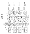
- Fig. 6 is a general block diagram depicting a communication system for demodulating receive data using the interference between lower one sub-channel and upper two sub-channels, comprising four transmitters 121, 122, 123 and 124 for transmitting data independently via four sub-channels, ch-1, ch0, ch+1 and ch+2, many cross-talk paths 131 ij having the coupling coefficient ⁇ ij from the i-th sub-channel to the j-th sub-channel, four receivers 150, 160, 170 and 180 which are installed for each sub-channel for receiving data from the corresponding sub-channel and performing soft decision for the receive data, and means 191 and 192 for inputting the soft decision target value of each receiver to the receiver 160 of the target channel ch0.
- Means for inputting the other receivers is omitted in Fig. 6, but can be regarded as the same for the receiver 160.
- 132 - 139 and 140 - 143 are synthesizing units for synthesizing ICI signals and noises
- the receiver 160 of the sub-channel ch0 adjusts its own soft decision target value using the soft decision target values which were input from the receivers 150, 170 and 180 of the lower and upper sub-channels ch-1, ch+1 and ch+2, and decides "0" or "1" of the receive data based on the soft decision target value.
- the other receivers as well adjust their own soft decision target values using the soft decision target values which were input from the receivers of the lower and upper sub-channels, and decides "0" or "1" of the receive data based on the adjusted soft decision target values.
- the receive information of the target sub-channel can be decided as "0" if ln D 0 > 0, and the receive information of the target sub-channel is "1" if ln D 0 ⁇ 0.
- the signal of the target sub-channel affected by ICI from the lower and upper sub-channels is expressed as the linear coupling of the signals S* -1j , S* 1j and S* 2j transmitted by the upper and lower sub-channels, and the target channel signal S* 0j by the cross-talk coefficient ⁇ .
- the index j of S j in the expressions (32) and (33) indicates the signal number, and is determined by pairing the symbols D -1 , D 1 , D 2 and D 0 in the lower sub-channel, upper sub-channel and target sub-channel.
- ln D 0 a + b 2 - c + d 2 + ln cosh( a - b 2 ) - ln cosh( c - d 2 )
- Fig. 7 and Fig. 8 are block diagrams depicting a receiver of the target sub-channel of the present invention in the case when the cross-talk from upper two sub-channels and lower one sub-channel exist, which are separated in the figures by a dash and dotted line, and implements the computation of the right side member of the expression (41).
- Fig. 7 shows the configuration of the left side of the receiver
- Fig. 8 shows the right side thereof. If the receiver in Fig. 7 and Fig.
- this receiver 8 is the receiver of the target channel ch0, this receiver has a configuration combining the receiver of the three sub-channel model which receives cross-talk from the channels ch+1 and ch+2, and the receiver of the two sub-channel model which receives cross-talk from the channel ch1, and the expression (41) becomes the sum of the values at the points P1, P2 and P3 in Fig. 7 and Fig. 8.
- the receiver 160 of the target sub-channel comprises a correlation unit 161, first - third computing units 162 - 164, synthesizing unit 165 and decision unit 166.
- the first computing unit 162 has a configuration the same as the configuration enclosed by a dash and dotted line in Fig. 5, and computes the second - fifth terms of the right side member of the expression (28) and expressions (29) and (30) for the signals S 0 (t) ,... S 3 (t) out of the signals S 0 (t), S 1 (t),...S 7 (t).
- the second computing unit 163 has the same configuration as the configuration enclosed by the dash and dotted line in Fig. 5, and computes the second to fifth terms of the right side member of the expression (28) and the expressions (29) and (30) for the signals S 4 (t),...S 7 (t) out of the signals S 0 (t), S 1 (t), ... S 7 (t). However in the expressions (28), (29) and (30), S 0 (t) ... S 3 (t) are replaced with S 4 (t) ... S 7 (t).
- the synthesizing unit 165 synthesizes the computing result of the right side member of the expression (27) for the signals S 0 (t) ... S 3 (t), that is A + B 2 - C + D 2 + ln cosh( A - B 2 ) - ln cosh( C - D 2 ) and the computing result of the right side member of the expression (27) for the signals S 4 (t) ...
- the third computing unit 164 corrects the computing result based on the soft decision data ln D -1 of the lower sub-channel ch-1, and performs predetermined computation on the correction result, and inputs it to the synthesizing unit 165.
- the values of the first - fifth terms of the expression (28) for the signals S 0 (t), S 1 (t), S 2 (t) and S 3 (t) are expressed as 1 ⁇ - 5 ⁇
- the values of the first - fifth terms of the expression (28) for the signals S 4 (t), S 5 (t), S 6 (t) and S 7 (t) are expressed as 1 ⁇ ' - 5 ⁇ '
- the output of the soft decision data ln D -1 operating unit 164a is expressed as 6 ⁇
- the value of the point P2 becomes In cosh(1/2) • [ ⁇ ( 2 + 4 - 2 ' - 4 ' )/2 + 6 - ⁇ ⁇ ⁇ + In cosh ⁇ (A - B) /2 ⁇ -ln cosh ⁇ (A' -B')/2 ⁇ ]
- the value of the point P3 becomes ln cosh(1/2) • [ ⁇ ( 3 ' + 5 ' - 3 - 5 )/2 + 6 +
- the symbol decision unit 166 decides the positive/negative of the ln D 0 (soft decision target value), and if positive the receive symbol is decided as "0", and if negative it is decided as "1". Also the symbol decision unit 166 feeds back the ln D 0 (soft decision target value) to the decision result operating unit of the receive units 150, 170 and 180 of the lower and upper sub-channels.
- the receiver of the target sub-channel ch0 adjusts its own bit decision target value ln D 0 using the soft decision target values ln D +1 , ln D +2 and ln D -1 in the sub-channels other than the target sub-channel, and decides the receive data based on this soft decision target value.
- each decoder transfers the information to the other decoders, and refines the estimated posterior probability sequentially using the information derived by the other decoders.
- the information derived from one sub-channel is used to refine the estimated posterior probability of the other channel after non-linear processing, and the information derived from the latter sub-channel is used to refine the estimated posterior probability of the former channel.
- an individual decoder output is hard bit decision (hard decision) format in the turbo decoder, sharing information has few advantages.
- a hard bit decision is similar to the decision feedback equalizer proposed by Viterbo and Fazel in the above mentioned Document 2 for canceling ICI.
- the hard bit decision is executed only at the end of a repeat.
- ln D -1 , ln D 1 and ln D 2 acquired in the previous step are applied to the decision expressions (35) - (36) and (41) to compute the new estimate value of the posterior probability of the target sub-channel.
- the output of one sub-channel receiver is used as the prior probability for the other receivers.
- (A) is QPSK modulated original data
- (B) are signals deteriorated by ICI
- (D) is the receive data after one repeat according to the present invention
- (E) is the constellation of the receive data after the second repeat according to the present invention.
- the dispersion in constellation is small, and the BER is improved to become smaller. As the number of repeats increases, the dispersion in constellation decreases further, and BER is further improved.
- Eb/N 0 is a ratio of the average receive signal energy Eb against the background noise power spectrum intensity N 0 per bit.
- a DMT base communication system As an application of the turbo receiver of the present invention, a DMT base communication system is considered.
- Fig. 11 is a block diagram depicting the DMT base communication system using this turbo receiver, and has a configuration where the turbo receiver of the present invention is disposed in the subsequent stage of the FFT section of the receiver in a known DMT communication system.
- the input beam stream with data rate R (bits/sec: bps) is transferred at the new rate R/N (bps) after the serial-parallel converter (S/P) 201 through N number of parallel sub-channels.
- the N point IFFT 202 combines the N parallel data and converts it into one set of real-time domain sample signals.
- P/S parallel-serial converter
- these N samples are converted into a serial format, and are continuously input into the digital-analog converter (DAC) 204.
- the output signal of the low pass filter (LPF) 205 at the DAC output side is the duration DMT signal.
- the transmission DMT signal is deteriorated by the white Gaussian noise n(t) and is sent to the DMT receiver 300.
- the receiver executes a function the opposite of the transmitter.
- the FFT 301 performs demodulation processing for the signals sent via each sub-channel as N matched filter arrays.
- the turbo 302 1 - 302 N perform sub-channel processing based on the turbo algorithm of the present invention, and by this, BER improves even if a frequency offset exists.
- 303 is the AD converter
- 304 is the serial-parallel converter
- 305 is the parallel-serial converter.
- Fig. 12 shows the BER performance of a conventional DMT base receiver and the BER performance of a DMT receiver which has the turbo processing function of the present invention, and performs three times and six times of turbo repeats.
- N 64
- the BER performance is shown for 2Eb/N 0 using a frequency offset normalized by an inter-channel frequency as a parameter, and "proposed" is indicated by the BER characteristic B and B' (ICI - four model) of the present invention.
- the BER characteristic improves as the frequency offset becomes smaller, and the BER characteristic is better in the "ICI - four model" of the present invention than the conventional device.
- the BER characteristic improves for 2dB.
- the present invention is a receiver based on an estimated posterior probability
- a receiver of each sub-channel is a turbo receiver for transferring information to the receivers of the adjacent sub-channels, and refines the estimated posterior probability using the information derived by the receivers of the adjacent sub-channels repeatedly. Therefore the turbo receiver of the present invention can improve BER performance considerably compared with a conventional matched filter receiver.
- the non-linear signal processing of the turbo algorithm of the present invention uses the information acquired by the adjacent sub-channels so as to maximize the posterior probability.
- the biggest improvement in BER is generated in a high S/N ratio area where ICI dominates Gaussian noise.
- the turbo receiver of the present invention can achieve good performance throughout a considerably wide rage of ICI coupling coefficients.
Landscapes
- Engineering & Computer Science (AREA)
- Signal Processing (AREA)
- Computer Networks & Wireless Communication (AREA)
- Power Engineering (AREA)
- Digital Transmission Methods That Use Modulated Carrier Waves (AREA)
- Mobile Radio Communication Systems (AREA)
- Noise Elimination (AREA)
- Radio Transmission System (AREA)
Abstract
The present invention is a multi-carrier communication system for transmitting/receiving signals via at least four sub-channels, comprising: a transmitter for transmitting data independently via the four sub-channels; a receiver comprising a receive unit disposed for each sub-channel for receiving data from a corresponding sub-channel and performing soft decision of the receive data; and means for inputting soft decision target values in receive units corresponding to three sub-channels other than a target sub-channel to a receive unit of the target sub-channel, wherein the receive unit of the target sub-channel adjusts its own soft decision target value using the soft decision target values that are input from the receive units of the other sub-channels, and decides the receive data based on this adjusted soft decision target value. <IMAGE>
Description
The present invention relates to a multi-carrier
communication system and a receiver thereof, and more
particularly to a multi-carrier communication system using
the interference between a target sub-channel and two or
more upper and lower sub-channels (ICI) and a receiver
thereof.
The bit error rate (BER) of the multi-carrier
communication system in filter bank modulation, DMT
modulation and FMT modulation can be improved by using
receive signals that include distortion by inter-channel
interference (ICI). Inter-channel interference occurs by
the malfunction of a system in communication systems, such
as OFDM - CDMA, or due to an unavoidable environment such as
the loss of orthogonality between sub-channels. Inter-channel
interference, which is called the "leak of spectrum
energy", at times the cross-talk between sub-channels, is
caused by a leak.
A major advantage of the turbo receiver of the present
invention is that the phenomenon of ICI is handled as a zero
mean Gaussian distribution random variable (e.g. Gaussian
approximation used in the following document 1 below), for
which a finite state discrete Markov process model is used.
For such an ICI model, simple Gaussian approximation seems
to be more practical because of the nature of ICI. The
turbo receiver of the present invention is based on a
maximum posterior probability estimation algorithm. In this
turbo receiver, information derived from one sub-channel
after non-linear processing refines the estimated maximum
posterior probability of the latter channel, and in the same
way, the information derived from the other sub-channel
refines the estimated maximum probability of the former sub-channel.
Document 1: K. Sathanathan and C. Tellambura: "Probability of error calculation of OFDM system with frequency offset", IEEE Trans. Commun., Vol. 49, NO. 11, Nov. 2001, pp. 1884 - 1888.
Document 1: K. Sathanathan and C. Tellambura: "Probability of error calculation of OFDM system with frequency offset", IEEE Trans. Commun., Vol. 49, NO. 11, Nov. 2001, pp. 1884 - 1888.
In the case of a multi-carrier communication system
where a band is divided into a plurality of sub-bands, which
are independent narrow bands, and the transmission data of
each sub-band is frequency-multiplexed and transmitted and
received, the selection of a filter set in a multi-carrier
communication system for filter bank modulation, DMT
(Discrete Multi-tone) modulation and FMT (Filtered Multi-tone)
modulation, has been executed under the constraint
that inter-symbol interference (ISI) and inter-channel
interference (ICI) are completely removed.
In an ideal transmission channel where there is no
Doppler shift and where there is no offset frequency between
transmitter/receiver and signal distortion does not occur,
this constraint guarantees the receiver that the recovery of
transmission symbols to be error free. However the
frequency offset which is generated in each channel, due to
inaccurate tuning of the oscillator and the Doppler shift,
causes BER deterioration due to a spectrum leak or ICI.
The only method to relax such deterioration of BER is
to minimize the frequency offset, and more particularly, to
maintain it to be within 1% of the sub-carrier frequency
interval. This method, however, requires accurate frequency
offset estimation, and also if the noise level is high when
multi-carrier signals mixed with noise are received, the
accuracy of frequency offset estimation is affected. Also
according to this method, the Doppler shift is not
consistent with respect to the transmission symbols in a
high-speed fading channel, and operation becomes inaccurate
in a high-speed fading channel which changes depending on
the time.
Here the case of a DMT base system and an ideal white
Gaussian noise (AWGN) channel is assumed. It is also
assumed that the level of inter-symbol interference ISI can
be ignored compared with the inter-channel interference ICI
and other noise signals. To simplify description, only a
target channel, the first adjacent sub-channel located below
the target sub-channel and the second adjacent sub-channel
located above the target sub-channel, are considered. Fig.
1 and Fig. 2 show the frequency response of the three
channels in the case when the frequency offset is zero (Fig.
1), and in the case when the frequency offset is not zero
(Fig. 2). The signals of the central frequencies f1, f2 and
f3 corresponding to the first, second and third sub-channels
are indicated by the vertical arrows in Fig. 1 and Fig. 2.
In Fig. 1 and Fig. 2, the sub-channel number 0 (ch0)
indicates the target sub-channel, the sub-channel number -1
(ch-1) is a sub-channel located below the target sub-channel
in the frequency scale, and the sub-channel number +1 (ch+1)
indicates the sub-channel located above the target sub-channel
in the frequency scale. If the cycle of the DMT
symbol is T, then the frequency scale is normalized with a
channel interval equal to 1/T. In other words, one unit of
the frequency scale is the channel interval. As Fig. 1
shows, when the frequency offset (normalized by the channel
interval) α is 0, the transfer function of the lower sub-channel
and the upper sub-channel, indicated by the solid
line A and the dotted line B in Fig. 1, gives infinite
attenuation in the central frequency f2 of the target sub-channel
(dotted line C). In the same way, the transfer
function of the target sub-channel gives infinite
attenuation in the central frequencies f1 and f3 of the
lower and the upper sub-channels. In other words, if the
frequency offset α is zero, ICI is not generated between
adjacent sub-channels. This means that if the frequency
offset is zero, the respective sub-channels intersect
orthogonally, and ICI does not exist at all.
If the frequency offset α is not zero, however, the
orthogonality of the sub-channels is affected, and ICI is
generated. Fig. 2 shows the spectrum characteristics of
each sub-channel of the DMT system when the frequency offset
α is not zero. The spectrum of adjacent channels cross at
-3dB, and the first side-lobe is -13dB, which is high. In
order to avoid a complex system model, the case when the
sub-channels which are distant for a 1 or 2 channel interval
interfere with each other will be considered below. It is
clear that the spectrum of an adjacent sub-channel has a
mutual gain which is not zero, which is indicated as α0-1,
α1-1, α10, α-10, α01 and α-11. In these notations the first
index of a indicates the interference source sub-channel,
and the second index indicates the interference target sub-channel.
In other words, α-10 indicates the leak transfer
coefficient (amplitude) from the lower sub-channel with the
sub-channel number -1 to the target channel with the sub-channel
number 0. α-11 indicates the leak transfer
coefficient (amplitude) from the lower sub-channel with the
sub-channel number -1 to the upper sub-channel with the sub-channel
number 1, α01 indicates the leak transfer
coefficient from the target sub-channel with the sub-channel
number 0 to the higher sub-channel with the sub-channel
number 1, α0-1 indicates the leak transfer coefficient from
the target sub-channel with the sub-channel number 0 to the
lower sub-channel with the sub-channel number -1, and α10
indicates the leak transfer coefficient from the higher sub-channel
with the sub-channel number +1 to the target sub-channel
with the sub-channel number 0. As described above,
if the frequency offset α is not zero, the mutual gain
which is not zero, that is ICI (cross-talk), is generated
between sub-channels.
Fig. 3 is a general model (four sub-channel model)
depicting the mutual ICI of four sub-channels in a DMT
system having frequency offset. Compared with the three
sub-channel model (see Fig. 4), according to the turbo
receiver of the present invention, the four sub-channel
model can improve the total system BER in more cases because
of the low roll off spectrum characteristics of DMT. 11, 12,
13 and 14 are the transmitters of the sub-channels ch-1, ch0,
ch+1 and ch+2, 21, 22, 23 and 24 are the receivers of each
sub-channel, 31, 32, 33 and 34 are the transmission lines of
each sub-channel. 4ij is a multiplier to multiply the sub-channel
signal Di by the leak transfer coefficient
(interference coefficient) αij of the sub-channel with the
number i to the sub-channel with the number j respectively,
51, 52, 53 and 54 are the first synthesizing units for
synthesizing the cross-talk (ICI) from the adjacent sub-channel
to its own sub-channel signal, 61, 62, 63 and 64 are
the second synthesizing units for synthesizing the cross-talk
(ICI) from the sub-channel which is distant from two
channel intervals to its own sub-channel signal, and 71, 72,
73 and 74 are the noise synthesizing units.
As Fig. 3 shows, the signals from the lower sub-channel
ch-1 leak into the target sub-channel ch0 via the cross-talk
coefficient α-10, the signals from the upper sub-channel ch+1
leak into the target sub-channel via the cross-talk
coefficient α10, and the signals from the upper sub-channel
ch+2 leak into the target sub-channel ch0 via the cross-talk
coefficient α20. Also the signals from the lower sub-channel
ch-2 leak into the target sub-channel via the cross-talk
coefficient α-20, but description thereof will be
omitted since this can be regarded as the same as the leak
from the ch+2. In the model in Fig. 3, the sub-channels
that cause mutual interference are limited to the upper and
lower sub-channels, but the number of sub-channels in the
entire communication system is not limited, so the model in
Fig. 3 can also be applied to a multi-carrier communication
system that has N number of sub-channels, where N is 4 or a
greater number. In such a case as well, interference to
each sub-channel is only from the lower two sub-channels and
the upper two sub-channels. In this case, the interference
coefficient indicates a chain of coefficients. The noise
components denoted as n1 (t), n2 (t), n3 (t) and n4 (t) in
Fig. 3 are statistically independent (no correlation)
because of the frequency orthogonality between the sub-channels.
The sub-channels are located in the frequency domain,
but this model can be applied not only to a DMT modulation
type or a filter bank modulation type system, but also to
other systems. The dimensions can be expanded to other
domains, such as space (space division multiplex axis) and
polarity.
The model in Fig. 3 is beneficial in terms of
understanding the physical process which causes ICI. The
problem of this model lies in accurately deciding the
receive signals of each sub-channel and the value of the
transmission information symbols (a sign if a binary number).
One possible method to reduce ICI in a receiver is
applying the decision feedback equalizer (DFE) to cancel ICI,
which is proposed in the following document 2.
Document 2: Viterbo and K. Fazel, "How to combat long echoes in QFDM transmission schemes: Sub-channel equalization or more powerful channel coding," Proc. IEEE Globecom '95, Singapore, Nov. 1995, pp. 2069 - 2074.
Document 2: Viterbo and K. Fazel, "How to combat long echoes in QFDM transmission schemes: Sub-channel equalization or more powerful channel coding," Proc. IEEE Globecom '95, Singapore, Nov. 1995, pp. 2069 - 2074.
If the output of an individual receiver is in hard bit
decision (hard decision) format, then sharing information
among sub-channels has only a few benefits. This restricts
the operation range of DFE which uses a hard decision.
The above mentioned approach is effective in many
practical cases, but is for minimizing the effect of ICI,
and is the second best approach. Since ICI includes
information on transmission symbols, it is possible to
remodulate the receive signals quite well by using this
transmission symbol information included in ICI.
With the foregoing in view, it is an object of the
present invention to improve BER performance using the ICI
in a communication system where ICI exists.
It is another object of the present invention to
decrease BER based on the posterior probability using ICI.
The present invention is a multi-carrier communication
system for transmitting/receiving signals via at least four
sub-channels, comprising a transmitter for transmitting data
independently via four channels, a receiver comprising a
receive unit disposed for each sub-channel for receiving
data from a corresponding sub-channel and performing soft
decision of the receive data, and means for inputting soft
decision target values in the receive units corresponding to
sub-channels other than a target sub-channel to a receive
unit of the target sub-channel, wherein the receive unit of
the target sub-channel adjusts its own soft decision target
value using the soft decision target values that are input
from the receive units of the other sub-channels, and
decides the receive data based on the adjusted soft decision
target value.
The receive unit of the target sub-channel further
comprises means for computing a difference between a
probability that the data received from the target sub-channel
is one value of a binary and a probability that the
data is the other value of a binary as the soft decision
target value, considering degree of coupling of cross-talk
paths, means for adjusting the soft decision target value of
the target sub-channel using the soft decision target values
that are input from the receive units of the other sub-channels,
and a decision unit for deciding the receive data
based on adjusted the soft decision target value.
Fig. 4 is a general block diagram depicting a
communication system that demodulates receive data using the
interference between a total of two sub-channels, lower and
upper, and is a case when the number of sub-channels is
three. The intent of the present invention is to provide a
communication system having at least four sub-channels (four
sub-channel model), but a communication system having three
sub-channels (three sub-channel model) will be described
first to assist in understanding the present invention.
The communication system in Fig. 4 comprises three
transmitters, 21, 22 and 23, for transmitting data
independently via the three sub-channels, ch-1, ch0 and ch+1
respectively, many cross-talk paths 31ij having a coupling
coefficient αij to the i-th to the j-th sub-channel, three
receivers, 40, 50 and 60, which are installed for each sub-channel
for receiving data from the corresponding sub-channel
and performing the soft decision of the receive data,
and means 71 and 72 for inputting the soft decision target
value of each receiver to another receiver. 32 - 34 and 35
- 37 are synthesizing units for synthesizing ICI signals and
noise.
The receiver 50 of the sub-channel ch0 adjusts its own
soft decision target value using the soft decision target
values which were input from the receivers 40 and 60 of the
lower and upper sub-channels ch-1 and ch+1, and decides "0"
or "1" of the receive data based on the soft decision target
value. In the same way, the other respective receivers
adjust its own soft decision target value using the soft
decision target values which were input from the receivers
of the lower and upper sub-channels, and decides "0" or "1"
of the receiver data based on the soft bit decision target
value.
An algorithm for the receiver of the target sub-channel
ch0 to demodulate the receive signals in the communication
system shown in Fig. 4, will be described.
The principle of the demodulation algorithm is to
derive the value InD0 which indicates the difference of the
posterior probability P (D0 = +1/y(t)) of the information
symbol received by the target sub-channel ch0 becoming "0"
(= +1) and the posterior probability P (D0 = -1/y(t)) of
this becoming "1" (= -1). This is because if the difference
InDo of the posterior probability can be derived, it can be
decided whether the receive information symbol is "0" or "1".
In other words, the probability difference InDo of the
target sub-channel is the difference between the posterior
probability P (D0 = +1/y(t)) of the receive information
symbol becoming "0" (= +1), and the posterior probability P
(D0 = -1/y (t)) of this becoming "1" (= -1), so if InD0 > 0,
then the receive information of the target sub-channel is
"0", and if InD0 < 0, then the receive information of the
target sub-channel is decided as "1". According to the
above, the value InD0, to indicate the difference of the
posterior possibility, is derived.
It is assumed that the binary information is
transmitted as the signal S*ij (t) via the two adjacent sub-channels.
The index i of S*ij (t) is determined by the sign
of the information symbol Di (i = -1, 0 or 1) in sub-channel
i. In other words,
if Di = +1, then j = 0
if Di = -1, then j = 1
Hereafter to simplify notation, the time dependency of S*ij
(t) in expressions is omitted. In other words, S*ij (t) is
denoted as S*ij .
It is assumed that the transmission information symbol
Di is statistically independent (no correlation) and is an
equally distributed probability variable. As Fig. 4 shows,
the signal of the target sub-channel affected by ICI from
the lower and upper sub-channels is expressed as the linear
coupling of the signals S*-1j and S*1J transmitted by the
upper and lower sub-channels and the target channel signal
S*0j by the cross-talk coefficient α. The cross-talk
coefficient α is a value according to the leak of cross-talk.
If the information symbol D0 of the target channel is
+1, then the receive signal Sj (j = 0 - 3) of the target
channel becomes
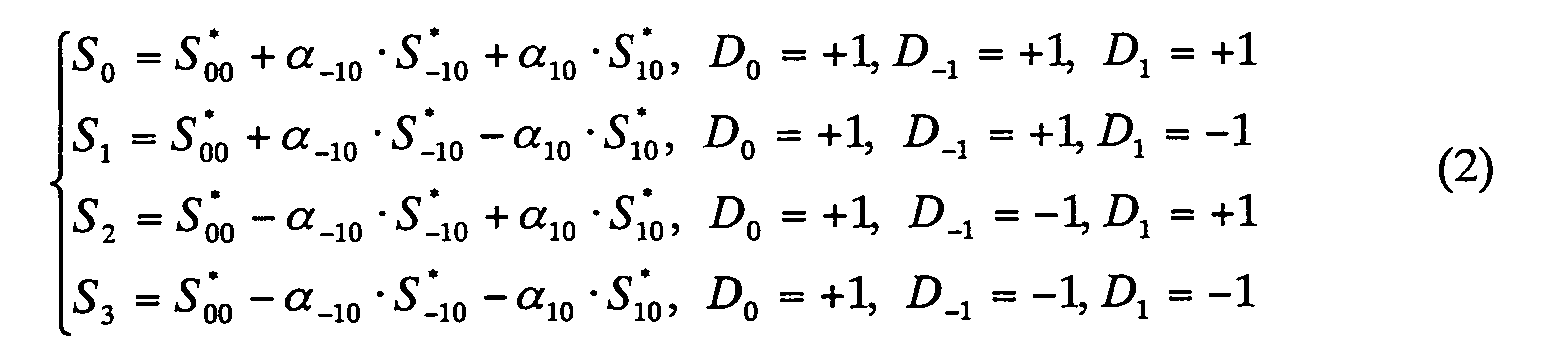 depending on whether the signals D-1 and D1 of the lower and
upper sub-channels are +1 or -1. j of the signal Sj
indicates the signal number. In the same way, if the
information symbol D0 of the target channel is -1, then the
receive signal Sj (j = 4 - 7) of the target channel becomes
depending on whether the signals D-1 and D1 of the lower and
upper sub-channels are +1 or -1. j of the signal Sj
indicates the signal number. In the same way, if the
information symbol D0 of the target channel is -1, then the
receive signal Sj (j = 4 - 7) of the target channel becomes
 depending on whether the signals D-1 and D1 of the lower and
upper sub-channels are +1 or -1.
depending on whether the signals D-1 and D1 of the lower and
upper sub-channels are +1 or -1.
After introducing ICI, Sj (j = 0, 1, 2, ... 7) is
used as eight signals in the input of the receiver of each
sub-channel. The index j of Sj in the expressions (2) and
(3) indicates the signal number, and is determined by
pairing the symbols D-1, D1 and D0 in the lower sub-channel,
upper sub-channel and target sub-channel.
By considering the following [1] and [2], an algorithm
for optimum reception can be further developed. In other
words, by considering [1] that the signs of some information
signals are the opposite, that is -S*-10 = -S*-11, S*00 = -S*01,
and S*10 = -S*11, and [2] to transmit information symbols a
same signal is used for the lower and upper sub-channels and
target sub-channel, that is S*-10 = S*00 = S*10, and S*-11 = S*01
= S*11, the algorithm for optimum reception can be further
developed. The latter [2] indicates that all the sub-channels
have the same value and the information signals of
all the sub-channels have no difference in amplitude,
waveform and energy. In this case the signals of the
expressions (2) and (3) in each sub-channel become a pair,
having opposite signs, as shown in the following expressions.
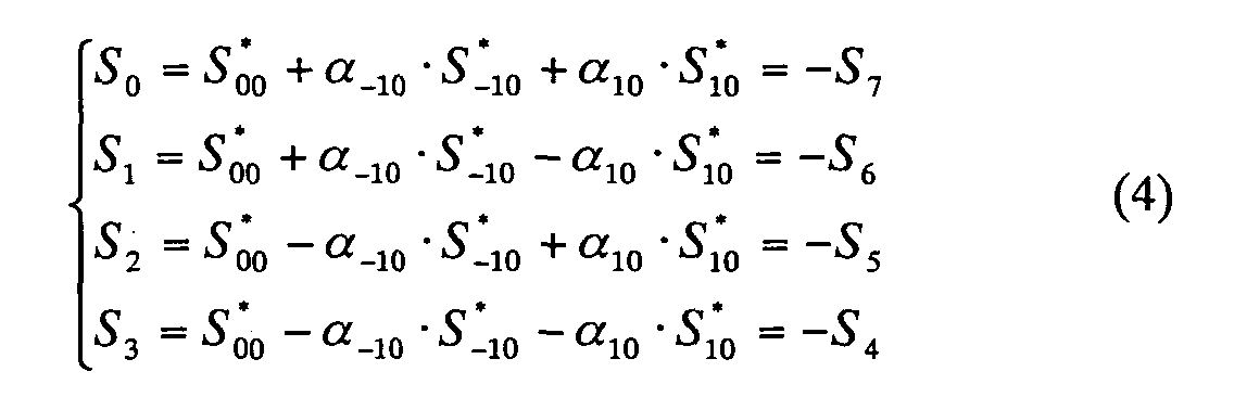 From the expression (2), (3) and (4), the posterior
probability to receive the signal Sj, that is the posterior
probability P (Sj/y (t)) of the receive signal becoming Sj,
is given by the following expression.
From the expression (2), (3) and (4), the posterior
probability to receive the signal Sj, that is the posterior
probability P (Sj/y (t)) of the receive signal becoming Sj,
is given by the following expression.
 where
where
k0 is a normalized factor
j is a signal number (j = 0, 1, ... 7),
y(t) is a synthesized signal (y (t) = Sj + n (t)) of the signal series Sj involving ICI and the white Gaussian noise n(t) having the spectrum power intensity N0,
Papr (Sj) is a prior probability of the receive signal Sj, and
P (y(t)/Sj) is a conditional probability, and is a probability where the transmitted sign signal is Sj when the receive signal is y(t).
k0 is a normalized factor
j is a signal number (j = 0, 1, ... 7),
y(t) is a synthesized signal (y (t) = Sj + n (t)) of the signal series Sj involving ICI and the white Gaussian noise n(t) having the spectrum power intensity N0,
Papr (Sj) is a prior probability of the receive signal Sj, and
P (y(t)/Sj) is a conditional probability, and is a probability where the transmitted sign signal is Sj when the receive signal is y(t).
In the prior probability Papr (Sj) (j = 0, 1, ... 7)
is expressed as a cross-product of the prior probability of
the signal of the target sub-channel becoming S*00 or S*01
and the posterior probability of the information signal S*ij
in the two adjacent sub-channels. In other words, if D0 =
+1, the prior probability Papr (Sj) becomes
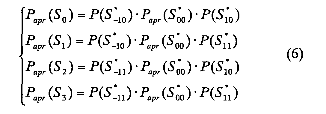 and if D0 = -1, the prior probability Papr (Sj) becomes
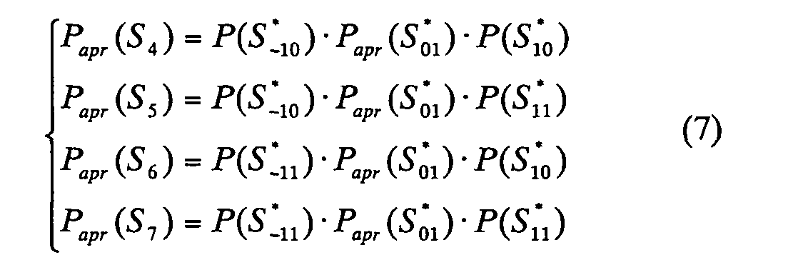
In expressions (6) - (7), Papr (Sj) is a prior
probability (transmission probability) of the information
signal Sj with the number j in the target sub-channel being
transmitted. Prior probability Papr (S*ij) depends on the
statistics of the data generation source, and in practical
terms it is assumed to be equal to ½. Probability P (S*ij)
is the posterior probability of the receive signal S*ij,
which is different from the prior probability Papr (S*ij), and
can be estimated at the receive side with high reliability,
so P (S*ij) ≈ P (S*ij/y(t)). This is the best estimate of
P(S*ij) in the white Gaussian noise channel. And based on
this assumption, the expressions (6) and (7) can be
rewritten as

 or when a different relationship exists between the
information signal S*ij and the transmission information
signal Di (see expression (1)), a substitution of P (S*ij) =
P (Di = i/y(t)) is possible in expression (6) and (7), and
expressions (6) and (7) can be expressed by the following
expressions. Here P (S*ij) is a probability of the i-th
sub-channel Di becoming j
or when a different relationship exists between the
information signal S*ij and the transmission information
signal Di (see expression (1)), a substitution of P (S*ij) =
P (Di = i/y(t)) is possible in expression (6) and (7), and
expressions (6) and (7) can be expressed by the following
expressions. Here P (S*ij) is a probability of the i-th
sub-channel Di becoming j
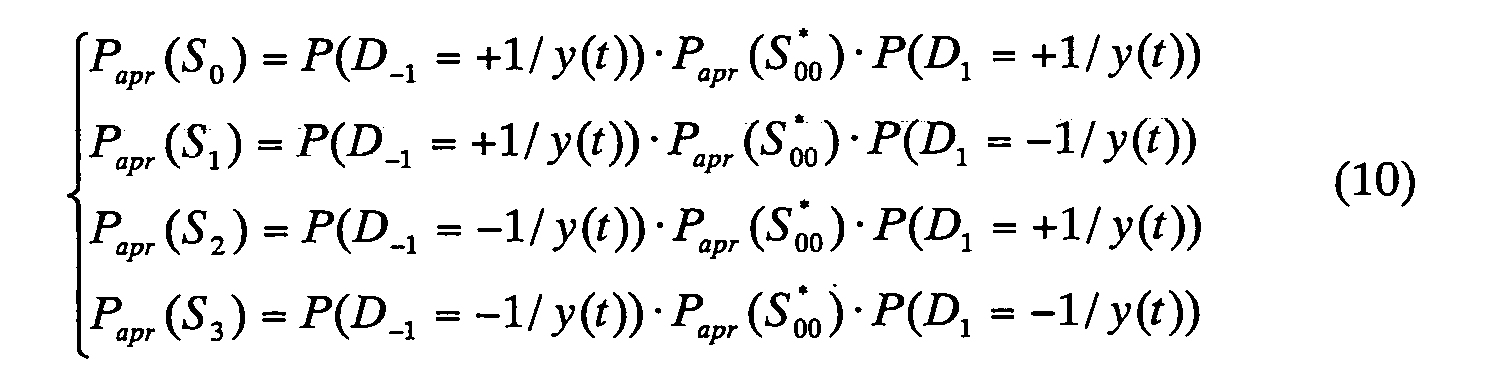
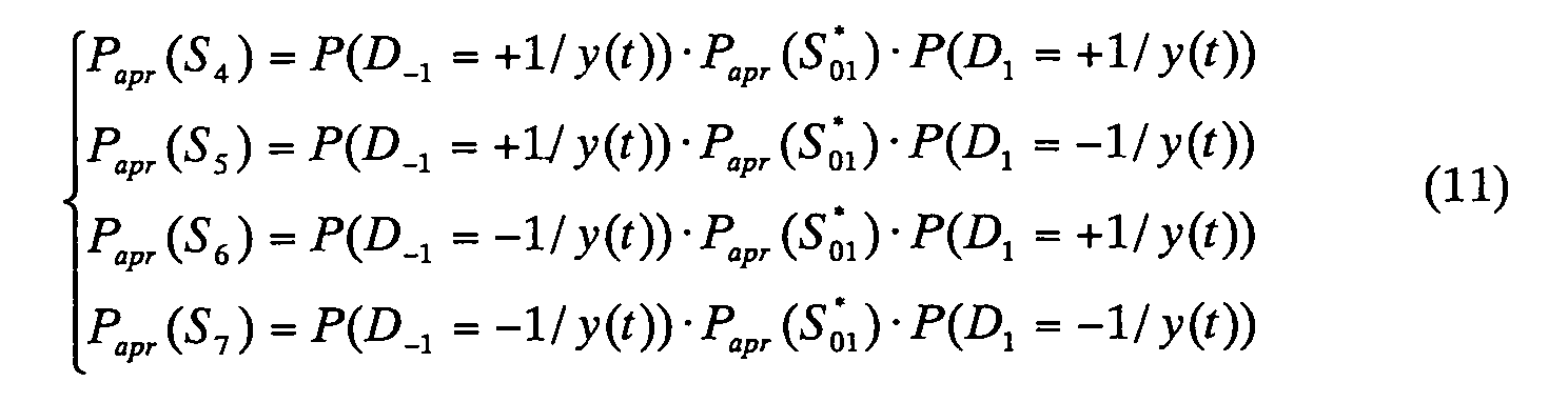
In the expressions (10) and (11) the prior probability
Papr (Sj) (j = 0, 1, 2, . . . 7) of the receive signal Sj in
the target sub-channel is expressed by the cross-channel
product of the prior transmission probability Papr (S*ij) of
the information signal S*ij and the posterior probability of
the information symbol Di received by the lower and upper
adjacent channels being +1 or -1.
In the turbo receiver (maximum likely receiver) of the
present invention, the sign of the receive information
symbol D0 of the target sub-channel is determined as follows.
That is, the probability of the receive information symbol
D0 of the target sub-channel (number 0) being +1, which is P
(D0 = +1/y(t)) and the probability of D0 being -1, which is
P (D0 = -1/y(t)) are determined respectively, and the sign
of the receive information symbol D0 is determined by
comparing the values thereof, or comparing the difference of
the logarithm thereof and the threshold value.
The posterior probability P (D0 = j/y(t)) of the
receive information symbol D0 of the target sub-channel
being j can be acquired as the posterior probability of the
signals of which D0 is j being received. Therefore the
posterior probability P (D0 = +1/y(t)) is a probability of
the receive information signal D0 of the target sub-channel
becoming "0" (= +1) can be determined as follows. That is,
the signal to transmit the information symbol of "0" (= +1)
in the target sub-channel is S0 - S3 according to the
expressions (1) and (2), so the posterior probability P (D0
= +1/y(t)) of the receive information symbol D0 of the
target sub-channel becoming "0" (= +1) becomes the sum of
the posterior probability to receive the signals S0 - S3,
which can be determined by the expression (12a). In the
same way, the posterior probability P (D0 = -1/y(t)) of the
receive information symbol D0 of the target sub-channel
becoming "0" (= -1) can be determined by the expression
 If the expression (5) is applied to (12a) (where k0 = 1),
the expression (13) is established,
If the expression (5) is applied to (12a) (where k0 = 1),
the expression (13) is established,
 and if the expression (5) is applied to (12b) (where k0 = 1),
the expression (14) is established.
and if the expression (5) is applied to (12b) (where k0 = 1),
the expression (14) is established.
 If the expressions (10) and (11) are substituted for the
expressions (13) and (14) and y(t) of P (Di = ±1/y(t)) is
omitted for simplification (that is P (Di = ±1/y(t)) = P (Di
= ±1)), then the expressions (15) and (16) are acquired.
If the expressions (10) and (11) are substituted for the
expressions (13) and (14) and y(t) of P (Di = ±1/y(t)) is
omitted for simplification (that is P (Di = ±1/y(t)) = P (Di
= ±1)), then the expressions (15) and (16) are acquired.

 Then the expression (15) is further transformed, and the
expressions (17a) and (17b) are acquired.
Then the expression (15) is further transformed, and the
expressions (17a) and (17b) are acquired.
P (D 0 = +1/y (t )) = k·P apr (S * 00 )·[ P (D -1 = +1)·P (D 1 = +1)·P (y (t )/S 0 ) + P (D -1 = +1)·P (D 1 = -1)·P (y (t )/S 1 ) ]+ k·P apr (S * 00 )·[ P (D -1 = -1)·P (D 1 = +1)·P (y (t )/S 2 ) + P (D -1 = -1)·P (D 1 = -1)·P (y (t )/S 3 ) ]
P (D 0 = +1/y (t )) = k·P apr (S * 00 )·[ P (D -1 = +1)·{P (D 1 = +1)·P (y (t )/S 0 ) + P (D 1 = -1)·P (y (t )/S 1 )}]+ k·P apr (S * 00 )·[ P (D -1 = -1)·{P (D 1 = +1)·P (y (t )/S 2 ) + P (D 1 = -1)·P (y (t )/S3 )} ]
In the same way, the expression (16) is transformed, and the
expressions (18a) and (18b) are acquired.
P (D 0 = -1/y (t )) = k·P apr (S * 01 )·[P(D -1 = +1)·P (D 1 = +1)·P (y (t )/S 4 ) + P (D -1 = +1)·P (D 1 = -1)·P (y (t )/S 5 )]+ k·P apr (S * 00 )·[ P (D -1 = -1)·P (D 1 = +1)·P (y (t )/S 6 ) + P (D -1 = -1)·P (D 1 = -1)·P (y (t )/S 7 ) ]
P (D 0 = -1/y (t )) = k·P apr (S * 01 )·[ P (D -1 = +1)·{P (D 1 = +1)·P (y (t )/S 4 ) + P (D 1 = -1)·P (y (t )/S 5 )}]+ k·P apr (S * 01 )·[ P (D -1 = -1)·{P (D 1 = +1)·P (y (t )/S 6 )+P (D 1 = -1)·P (y (t )/S 7 )}]
If the posterior probabilities P (D0 = +1/y(t)) and P
(D0 = -1/y(t)) for the receive information symbol D0 of the
target sub-channel becoming "0" (= +1) and "1" (= -1) are
determined as above, the values are compared or the
difference of the logarithm thereof and the threshold value
are compared so as to determined the sine (+1 or -1) of the
receive information symbol.
Whether the information symbol D0 of the target sub-channel
is +1 or -1 is decided by computing P (D0 = +1/y(t))
and P (D0 = -1/y(t)) first, then by using the expressions
(19a) and (19b),
P (D 0 = +1/y (t )) P (D 0 = -1/y (t )) >1
P (D 0 = +1/y (t )) P (D 0 = -1/y (t )) <1
and if (19a), then it is decided as D0 = +1, and if (19b),
then it is decided as D0 = -1.
Whether the information symbol D0 of the target sub-channel
is +1 or -1 is decided by computing
In P(D 0 = +1/y(t)) - ln P(D 0 = -1/y(t)) (ln is a logarithm with an e base), then deciding the negative/positive of the result. Ifln P (D 0 = +1/y (t )) - ln P (D 0 = -1/y (t )) >0
then it is decided as D0 = +1, and if
In P (D 0 = +1/y (t )) - ln P (D 0 = -1/y (t )) <0
then it is decided as D0 = -1.
In P(D 0 = +1/y(t)) - ln P(D 0 = -1/y(t)) (ln is a logarithm with an e base), then deciding the negative/positive of the result. If
Since the transmission symbol D0 is statistically
independent (no correlation) and is an equally distributed
probability variable, the following expression is
established.
 As expression (20) shows, the common multiplier in the
expressions (17b) and (18b) does not affect the decision
rule, so the expressions (17b) and (18b) become the
expressions (21) and (22).
As expression (20) shows, the common multiplier in the
expressions (17b) and (18b) does not affect the decision
rule, so the expressions (17b) and (18b) become the
expressions (21) and (22).
P (D 0 = +1/y (t )) = P (D -1 = +1)·{P (D 1 = +1)·P (y (t )/S 0 ) + P (D 1 = -1)·P (y (t )/S 1 )} + P (D -1 = -1)·{P (D 1 = +1)·P (y (t )/S 2 ) + P (D 1 = -1)·P (y (t )/S 3 )}
P (D 0 = -1/y (t )) = P (D -1 = +1)·{P (D 1 = +1)·P (y (t )/S 4 )+P (D 1 = -1)·P (y (t )/S 5 )} + P (D -1 =-1)·{P (D 1 = +1)·P (y (t )/S 6 )+P (D 1 = -1)·P (y (t )/S 7 )}
If the expressions (21) and (22) are transformed considering
the algebraic sameness of the following expression,
ln (e X + e Y ) = X + Y 2 + ln 2 + ln cosh( X - Y 2 )
then the following expressions (23) and (24) are established.
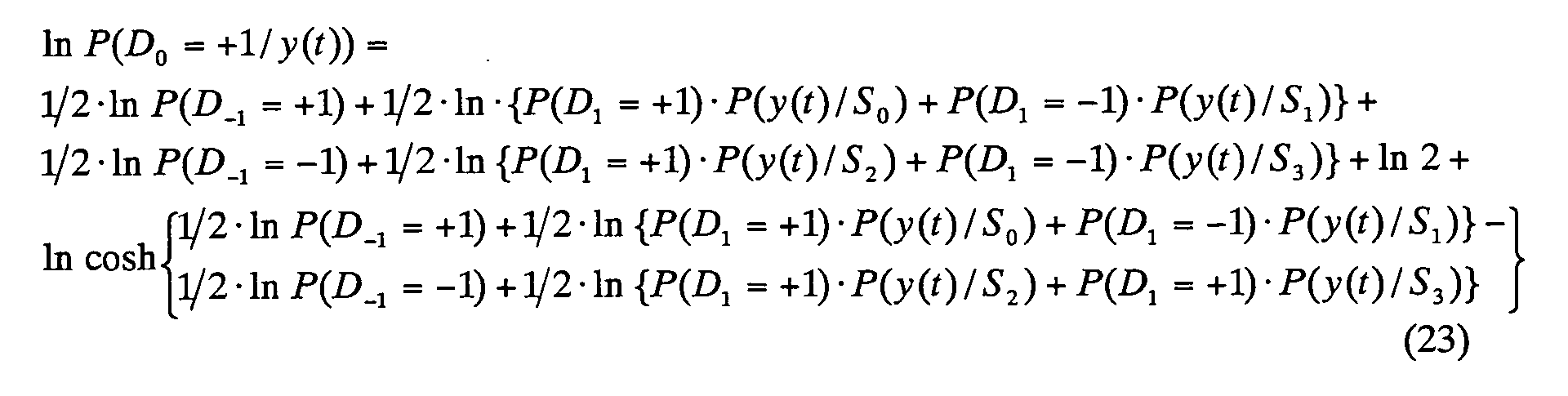

ln P (D 0 = +1/y (t )) = A + B 2 + ln 2 + In cosh( A - B 2 )
In P (D 0 = -1/y (t )) = C + D 2 + ln 2 + In cosh( C - D 2 )
Here if the expressions (25) and (26) are used, then A, B, C
and D become as follows.
A = ln P (D -1 = +1) + ln {P (D 1 = +1)·P (y (t )/S 0 ) + P (D 1 = -1)·P (y (t )/S 1 )}
B = ln P (D -1 = -1) + ln {P (D 1 = +1)·P (y (t )/S 2 ) + P (D 1 = -1)·P (y (t )/S 3 )}
C = ln P (D -1 = +1) + ln {P (D 1 = +1)·P (y (t )/S 4 ) + P (D 1 = -1)·P (y (t )/S 5 )}
D = ln P (D -1 = -1) + ln {P (D 1 = +1)·P (y (t )/S 6 ) + P (D 1 = -1)·P (y (t )/S 7 )}
If the expressions (25) and (26) are applied to the
left side member of the expressions (19c) and (19d), the new
decision expression becomes as follows.
ln D 0 = A + B 2 - C + D 2 + ln cosh( A - B 2 ) - ln cosh( C - D 2 ) >/< 0
By considering the relationship of
 acquired by the expression (5) and the expression (4), each
term constituting the new decision expression (27) can be
rewritten as follows.
acquired by the expression (5) and the expression (4), each
term constituting the new decision expression (27) can be
rewritten as follows.
Hereln Di = ln P (Di = +1) - ln P (Di = -1).

 In the above description, ln Di = ln P (Di = +1/y(t)) - In P
(Di = -1/y(t)) is the logarithmic difference of the
posterior probabilities of the signal Di transmitted in the
i-th sub-channel being +1 and -1 (soft decision value of the
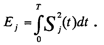
i-th sub-channel). It is assumed that the energy of the
signal Sj (t) is Ej, and
In the above description, ln Di = ln P (Di = +1/y(t)) - In P
(Di = -1/y(t)) is the logarithmic difference of the
posterior probabilities of the signal Di transmitted in the
i-th sub-channel being +1 and -1 (soft decision value of the
i-th sub-channel). It is assumed that the energy of the
signal Sj (t) is Ej, and
 (A-B), (C-D) of the
expression (27) becomes as follows.
(A-B), (C-D) of the
expression (27) becomes as follows.

 where
where
ΔE ∑ = (E 0 + E 1 ) - (E 2 + E 3 ) N 0
The expressions (27) - (30) define the optimum receiver
structure of binary signals involving ICI. As the
expressions (27) - (30) show, the decision information of
the adjacent channels is used to decide the sign of the
transmission information symbol D of a sub-channel. In the
decision rule of the expressions (27) - (30), ln D-1 and ln
D+1 indicate the logarithmic difference of the posterior
probability of the information symbol in the lower sub-channel
(ch-1) and the upper sub-channel (ch+1) becoming +1
and the posterior probability of that becoming -1. All
calculations are in series, so when processing the data of
the target sub-channel, the latest posterior probability
from the adjacent channels can be used by repeat calculation.
Here
As described above, the algorithm is created such that
InD0, which is the soft decision target value, is computed
by the expressions (27) - (30), then "0" or "1" of the
receive symbol of the target sub-channel is decided
depending on the positive/negative of the soft decision
target value InD0.
Fig. 5 is a block diagram depicting a receiver of a three
sub-channel model, that is, a receiver based on the maximum
posterior probability using ICI (called a turbo receiver),
and shows the configuration of only the receive unit of the
target sub-channel, but the receive units of the other sub-channels
also have the same configuration. This receive
unit also has a configuration to execute the above mentioned
algorithm.
The receiver 50 of the target sub-channel further
comprises a correlation unit (can be a match fill) 51,
another channel decision result operating unit 52, first and
second non-linear units 53 and 54, and symbol decision unit
55.
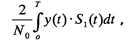
The multiplier 51a and integrator 51b of the
correlation unit 51 is a unit for computing
 of the decision expressions (28) - (30),
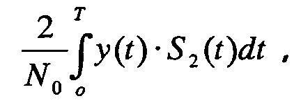
the multiplier 51c
and integrator 51d are units for computing
of the decision expressions (28) - (30),
the multiplier 51c
and integrator 51d are units for computing
 the multiplier 51e and integrator 51f are units for
computing
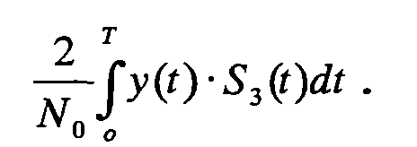
the multiplier 51e and integrator 51f are units for
computing
 and the multiplier 51g and
integrator 51h are units for computing
and the multiplier 51g and
integrator 51h are units for computing
 The addition unit 51i adds the integration output of the
integrators 51b and 51d, subtractor 51j subtracts the
integration outputs of the integrators 51b and 51d, the
addition unit 51k adds the integration outputs of the
integrators 51f and 51h, and the subtractor 51m subtracts
the integration outputs of the integrators 51f and 51h. The
addition unit 51n adds the outputs of the addition units 51i
and 51k, and outputs the first term of the right side member
of the expression (28), that is
The addition unit 51i adds the integration output of the
integrators 51b and 51d, subtractor 51j subtracts the
integration outputs of the integrators 51b and 51d, the
addition unit 51k adds the integration outputs of the
integrators 51f and 51h, and the subtractor 51m subtracts
the integration outputs of the integrators 51f and 51h. The
addition unit 51n adds the outputs of the addition units 51i
and 51k, and outputs the first term of the right side member
of the expression (28), that is
 The subtraction unit 51p subtracts the outputs of the
addition units 51i and 51k, and outputs
The subtraction unit 51p subtracts the outputs of the
addition units 51i and 51k, and outputs
 The division units 51q and 51r divide the input signal ½,
and output the result.
The division units 51q and 51r divide the input signal ½,
and output the result.
The other channel decision result operating unit 52
comprises the adders 52a - 52c, which compute the following
respectively.
The first non-linear unit 53 is a unit for computing ln
cosh of the second - fifth terms of the right side member of
the expression (28), and comprises the first and second non-linear
sections 53a and 53b. The addition units 71a and 71b
of the first non-linear section 53a compute the content of
{ } of the second and third terms of the right side member
of the expression (28) respectively. Here the (E0 - E1)/N0 =
ΔE1. ln cosh computing units 71c and 71d compute the second
and third terms of the right side member of the expression
(28) respectively, and the subtractor 71e subtracts the
computing result of the ln cosh computing unit 71d from the
computing result of the ln cosh computing unit 71c.
The addition units 71a' and 71b' of the second non-linear
unit 53b compute the content of { } of the fourth and
fifth terms of the right side member of the expression (28)
respectively. Here the (E2 - E3)/N0 = ΔE2 ln cosh computing
units 71c' and 71d' compute the fourth and fifth terms of
the right side member of the expression (28) respectively,
and the subtractor 71e' subtracts the computing result of
the ln cosh computing unit 71d' from the computing result of
the ln cosh computing unit 71c', and outputs the result.
The addition unit 53c synthesizes the outputs of the
adders 71e and 71e' and the division unit 53d divides the
synthesized signal by ½, and outputs the computing results
of the second - fifth terms of the expression (28).
The second non-linear unit 54 is a unit for computing
the first - third terms of the right side member of the
expressions (29) and (30). The addition units 54a and 54b
compute the first term of the right side member of the
expressions (29) and (30) respectively, the addition units
54c and 54d compute the second term and third term of the
right side member of the expressions (29) and (30)
respectively, the addition units 54e and 54f compute the
right side member of the expressions (29) and (30)
respectively, ln cosh computing units 54g and 54h compute
ln cosh A - B / 2and In cosh C - D / 2 respectively, and the subtraction
unit 54i computes the difference between the outputs of the
ln cosh computing units 54g and 54h, and outputs
In cosh A - B 2 - ln cosh C - D 2 .
The adder 55a of the symbol decision unit 55 adds the
output signal of the division unit 51r of the correlation
unit 51 and the output signal of the non-linear unit 53, and
outputs
A - B / 2 - C - D / 2, and the addition unit 55b generates the InD0 (soft decision target value) of the expression (27). The decision unit 55c decides whether InD0 is positive or negative, and decides that the receive symbol is "0" if positive, and that it is "1" if negative. The symbol decision unit 55 feeds back the computing result (soft decision target value) InD0 of the expression (27) to the other channel decision result operating units of the receive units 40 and 60 of the lower and upper adjacent sub-channels.
A - B / 2 - C - D / 2, and the addition unit 55b generates the InD0 (soft decision target value) of the expression (27). The decision unit 55c decides whether InD0 is positive or negative, and decides that the receive symbol is "0" if positive, and that it is "1" if negative. The symbol decision unit 55 feeds back the computing result (soft decision target value) InD0 of the expression (27) to the other channel decision result operating units of the receive units 40 and 60 of the lower and upper adjacent sub-channels.
Fig. 6 is a general block diagram depicting a
communication system for demodulating receive data using the
interference between lower one sub-channel and upper two
sub-channels, comprising four transmitters 121, 122, 123 and
124 for transmitting data independently via four sub-channels,
ch-1, ch0, ch+1 and ch+2, many cross-talk paths
131ij having the coupling coefficient αij from the i-th sub-channel
to the j-th sub-channel, four receivers 150, 160,
170 and 180 which are installed for each sub-channel for
receiving data from the corresponding sub-channel and
performing soft decision for the receive data, and means 191
and 192 for inputting the soft decision target value of each
receiver to the receiver 160 of the target channel ch0.
Means for inputting the other receivers is omitted in Fig. 6,
but can be regarded as the same for the receiver 160. 132 -
139 and 140 - 143 are synthesizing units for synthesizing
ICI signals and noises.
The receiver 160 of the sub-channel ch0 adjusts its own
soft decision target value using the soft decision target
values which were input from the receivers 150, 170 and 180
of the lower and upper sub-channels ch-1, ch+1 and ch+2, and
decides "0" or "1" of the receive data based on the soft
decision target value. In the same way, the other receivers
as well adjust their own soft decision target values using
the soft decision target values which were input from the
receivers of the lower and upper sub-channels, and decides
"0" or "1" of the receive data based on the adjusted soft
decision target values.
An algorithm for the receiver of the target sub-channel
ch0 to demodulate the receive symbol in the communication
system shown in Fig. 6 will be described.
The principle of the demodulation algorithm is deriving
the value InD0, which indicates the difference between the
posterior probability P (D0 = +1/y(t)) of the information
symbol received by the target sub-channel ch0 being "0" (=
+1) and the posterior probability P (D0 = -1/y(t)) of the
information symbol being "1" (= -1), just like the case of
the three sub-channel model. Since the probability
difference InD0 of the target sub-channel is the difference
between the posterior probability P (D0 = +1/y(t)) of the
receive information symbol being "0" (= +1) and the
posterior probability P (D0 = -1/y(t)) of the receive
information symbol being "1" (= -1), the receive information
of the target sub-channel can be decided as "0" if ln D0 > 0,
and the receive information of the target sub-channel is "1"
if ln D0 < 0.
It is assumed that binary information is transmitted as
signal S*ij(t) via two adjacent sub-channels. The index i
in S*ij(t) indicates the sub-channel number, and the index j
is determined by the sign of the information symbol Di (i =
-1, 0 or 1) in the sub-channel i. In other words,
if Di = +1, then j = 0
if Di = -1, then j = 1
Hereafter to simplify notation, the time dependency of
S*ij(t) in expressions is omitted. In other words, S*ij(t)
is denoted as S*ij.
As Fig. 6 shows, the signal of the target sub-channel
affected by ICI from the lower and upper sub-channels is
expressed as the linear coupling of the signals S*-1j, S*1j
and S*2j transmitted by the upper and lower sub-channels,
and the target channel signal S*0j by the cross-talk
coefficient α. The cross-talk coefficient α is a value
according to the leak of cross-talk. If the information
symbol D0 of the target channel is +1, then the receive
signal Sj (j = 0 - 7) of the target channel becomes
 depending on whether the signals D-1, D1 and D2 of the lower
and upper sub-channels are +1 or -1.
depending on whether the signals D-1, D1 and D2 of the lower
and upper sub-channels are +1 or -1.
j of the signal Sj indicates the signal number. In the same way, if the information symbol D0 of the target channel is - 1, then the receive signal Sj (j = 8 - 15) of the target channel becomes depending on whether the signals D-1, D1 and D2 of the lower
and upper sub-channels area +1 or -1.
depending on whether the signals D-1, D1 and D2 of the lower
and upper sub-channels area +1 or -1.
j of the signal Sj indicates the signal number. In the same way, if the information symbol D0 of the target channel is - 1, then the receive signal Sj (j = 8 - 15) of the target channel becomes
After introducing ICI, Sj (j = 0, 1, 2, ... 15) is
used as 16 signals at the input of the receiver of each sub-channel.
The index j of Sj in the expressions (32) and (33)
indicates the signal number, and is determined by pairing
the symbols D-1, D1, D2 and D0 in the lower sub-channel, upper
sub-channel and target sub-channel.
By considering the following [1] and [2], the algorithm
for optimum reception can be further developed. In other
words, by considering [1] that the signs of some information
signals are the opposite, that is S*-10 = -S*-11, S*00 = -S*01,
S*10 = -S*11, and S*-20 = -S*21, and [2] to transmit
information signals a same signal is used for the lower,
upper and target sub-channels, that is, S*-10 = S*00 = S*10 =
S*20 and S*-11 = S*01 = S*11 = S*21, the algorithm for optimum
reception can be further developed. The latter [2]
indicates that all the sub-channels have the same value and
the information signals of all the sub-channels have no
difference in amplitude, waveform and energy. In this case,
the signals of the expressions (32) and (33) in each sub-channel
become a pair, having opposite signs, as shown in
the following expressions.

Hereafter this case can be considered in the same way
as the three sub-channel model. In other words, just like
the case of the three sub-channel model, the posterior
probabilities P (D0 = +1/y(t)) and P (D0 = -1/y(t)) of the
receive information symbol D0 of the target sub-channel
becoming "0" (= +1) and "1" (= -1) are determined. If these
are determined, the sign (+1 or -1) of the receive symbol
can be determined by comparing these values or comparing the
difference of the logarithms thereof and the threshold value.
In other words, to determine whether the information symbol
D0 of the target sub-channel is +1 or -1, P(D 0 = +1/y(t)) / P(D 0 = -1/y(t)) is
computed first and compared with 1, and if the result is
greater than 1, it is decided that D0 = +1, and if the
result is smaller than 1, it is decided that
In P(D 0 = +1/y(t)) - ln P(D 0 = -1/y(t)) is computed and then the
negative or positive of the result is decided. In other
words, if positive it is decided that D0 = +1, and if
negative it is decided that D0 = -1. y(t) is a synthesized
signal (y (t) = Sj + n(t)) of the signal series Sj involving
ICI and the white Gaussian noise n (t) having spectrum power
intensity N0.
In the case of a four sub-channel model,
In P (D 0 = +1/y (t )) = a + b 2 + ln 2 + In cosh( a + b 2 )
In P (D 0 = -1/y (t )) = c + d 2 + ln 2 + In cosh( c - d 2 )
Here a, b, c and d are as shown in the following expressions.


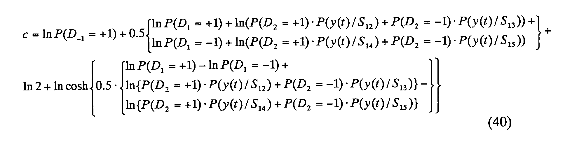
Finally ln D0 is given by the following expression
using the expressions (35) and (36).
ln D 0 = a + b 2 - c + d 2 + ln cosh( a - b 2 ) - ln cosh( c - d 2 )
Fig. 7 and Fig. 8 are block diagrams depicting a
receiver of the target sub-channel of the present invention
in the case when the cross-talk from upper two sub-channels
and lower one sub-channel exist, which are separated in the
figures by a dash and dotted line, and implements the
computation of the right side member of the expression (41).
Fig. 7 shows the configuration of the left side of the
receiver, and Fig. 8 shows the right side thereof. If the
receiver in Fig. 7 and Fig. 8 is the receiver of the target
channel ch0, this receiver has a configuration combining the
receiver of the three sub-channel model which receives
cross-talk from the channels ch+1 and ch+2, and the receiver
of the two sub-channel model which receives cross-talk from
the channel ch1, and the expression (41) becomes the sum of
the values at the points P1, P2 and P3 in Fig. 7 and Fig. 8.
The receiver 160 of the target sub-channel comprises a
correlation unit 161, first - third computing units 162 -
164, synthesizing unit 165 and decision unit 166. In the
figures, ∫dt is an integrator for computing
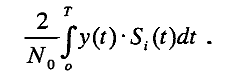 lnD i = ln P(D i = +1) - ln P(D i = -1) is the logarithmic
difference of the posterior probabilities of the signal Di
transmitted by the i-th sub-channel (i = -1, +1, +2)
becoming +1 or -1 (soft decision value in the i-th sub-channel).
Here the energy
of the signal Sj
(t) is Ej, which
is given by
lnD i = ln P(D i = +1) - ln P(D i = -1) is the logarithmic
difference of the posterior probabilities of the signal Di
transmitted by the i-th sub-channel (i = -1, +1, +2)
becoming +1 or -1 (soft decision value in the i-th sub-channel).
Here the energy
of the signal Sj
(t) is Ej, which
is given by
 Also
Also
ΔE ∑ = E 0 + E 1 - E 2 - E 3 N 0 , ΔE ∑ = E 4 + E 5 - E 6 - E 7 N 0 ,
ΔE ∑ = E 0 + E 1 + E 2 + E 3 - E 4 - E 5 - E 6 - E 7 N 0
ΔE 0 = E 0 - E 1 N 0 , ΔE 2 = E 2 - E 3 N 0 , ΔE 4 = E 4 - E 5 N 0 , ΔE 6 = E 6 - E 7 N 0
The correlation unit 161 is comprised of the computing
units (multiplier and integrator) for computing
 and the addition/subtraction circuit for computing S0' + S1',
S0' S1', S2' + S3', S2' - S3' . . . ,
∑Sj' (j = 0 - 7) when
and the addition/subtraction circuit for computing S0' + S1',
S0' S1', S2' + S3', S2' - S3' . . . ,
∑Sj' (j = 0 - 7) when
 are expressed as S0', S1' , S7'
respectively.
are expressed as S0', S1' , S7'
respectively.
The first computing unit 162 has a configuration the
same as the configuration enclosed by a dash and dotted line
in Fig. 5, and computes the second - fifth terms of the
right side member of the expression (28) and expressions
(29) and (30) for the signals S0 (t) ,... S3 (t) out of the
signals S0 (t), S1 (t),...S7 (t). In the addition unit 165a
of the synthesizing unit 165, the first term of the right
side member (= S0' + S1' + S2' + S3') of the expression (28)
is added, and computation of the expression (29) completes.
The second computing unit 163 has the same
configuration as the configuration enclosed by the dash and
dotted line in Fig. 5, and computes the second to fifth
terms of the right side member of the expression (28) and
the expressions (29) and (30) for the signals S4 (t),...S7
(t) out of the signals S0 (t), S1 (t), ... S7 (t). However
in the expressions (28), (29) and (30), S0 (t) ... S3 (t)
are replaced with S4 (t) ... S7 (t). In the addition unit
165a of the synthesizing unit 165, the first term of the
right side member( = S4' + S5' + S6' + S7') of the expression
(28) is added, and computation for the expression (29)
completes.
The synthesizing unit 165 synthesizes the computing
result of the right side member of the expression (27) for
the signals S0 (t) ... S3 (t), that is
A + B 2 - C + D 2 + ln cosh( A - B 2 ) - ln cosh( C - D 2 )
and the computing result of the right side member of the
expression (27) for the signals S4 (t) ... S7 (t), that is
A' + B' 2 - C' + D' 2 + ln cosh( A' - B' 2 ) - ln cosh( C' - D' 2 )
and adds the computing result of the third computing unit
164 to the synthesized result (value at the point P1 in the
figure), and inputs it to the decision unit 166 as ln D0 of
the expression (41).
The third computing unit 164 corrects the computing
result based on the soft decision data ln D-1 of the lower
sub-channel ch-1, and performs predetermined computation on
the correction result, and inputs it to the synthesizing
unit 165.
If the values of the first - fifth terms of the
expression (28) for the signals S0 (t), S1 (t), S2 (t) and S3
(t) are expressed as 1 ○ - 5 ○, the values of the first -
fifth terms of the expression (28) for the signals S4 (t),
S5 (t), S6 (t) and S7 (t) are expressed as 1 ○' - 5 ○', and the
output of the soft decision data ln D-1 operating unit 164a
is expressed as 6 ○, then the value of the point P2 becomes
In cosh(1/2) • [{(2 +4 -2 ' -4 ' )/2 +6 - ΔΣΣ }+
In cosh { (A - B) /2} -ln cosh{(A' -B')/2}]
and the value of the point P3 becomes
ln cosh(1/2) • [{(3 ' +5 ' -3 -5 )/2 +6 + ΔΣΣ } +
ln cosh { (C' - D') / 2 } -ln cosh{(C - D)/ 2}]
Therefore ln D0 (soft decision target value) after
synthesizing the values of the points P1, P2 and P3, that is
ln D0 (soft decision target value) given by the expression
(41) is input to the symbol decision unit 166. Here
ln D0 = (42) + (43) + (44) + (45).
The symbol decision unit 166 decides the
positive/negative of the ln D0 (soft decision target value),
and if positive the receive symbol is decided as "0", and if
negative it is decided as "1". Also the symbol decision
unit 166 feeds back the ln D0 (soft decision target value)
to the decision result operating unit of the receive units
150, 170 and 180 of the lower and upper sub-channels.
As described above, in the multi-carrier communication
system for transmitting/receiving signals via at least four
sub-channels, the receiver of the target sub-channel ch0
adjusts its own bit decision target value ln D0 using the
soft decision target values ln D+1, ln D+2 and ln D-1 in the
sub-channels other than the target sub-channel, and decides
the receive data based on this soft decision target value.
The above mentioned demodulation algorithm of the
receive data of the present invention is similar to the
turbo decoder of the turbo codes written in the following
document.
Document: M. C. Valenti and B. D. Woerner: "Variable latency turbo codes for wireless multimedia applications", Proc. Int. Symposium on Turbo codes and Related Topics, Brest, France, Sept. 1997, pp. 216 - 219.
Document: M. C. Valenti and B. D. Woerner: "Variable latency turbo codes for wireless multimedia applications", Proc. Int. Symposium on Turbo codes and Related Topics, Brest, France, Sept. 1997, pp. 216 - 219.
Because of the similarity with the turbo decoder, let
us call the algorithm of the present invention a "turbo
receiver". In the turbo decoder, each decoder transfers the
information to the other decoders, and refines the estimated
posterior probability sequentially using the information
derived by the other decoders. In the same way, in the
algorithm of the present invention as well, the information
derived from one sub-channel is used to refine the estimated
posterior probability of the other channel after non-linear
processing, and the information derived from the latter sub-channel
is used to refine the estimated posterior
probability of the former channel. If an individual decoder
output is hard bit decision (hard decision) format in the
turbo decoder, sharing information has few advantages. A
hard bit decision is similar to the decision feedback
equalizer proposed by Viterbo and Fazel in the above
mentioned Document 2 for canceling ICI. Here the hard bit
decision is executed only at the end of a repeat.
This structural similarity is because of the following
reasons. In other words, in the turbo receiver, just like
the case of turbo codes, the same information is transmitted
on the sub-channel having unrelated noise due to the
presence of ICI. Depending on the behavior of this
unrelated noise, the estimation (or the reliability of the
decision of) posterior probability can be improved using the
estimated posterior probability derived from other sub-channels.
Just like the case of the repeat turbo decoder, the
algorithm of the present invention performs one or more
repeats before the final decision for the received
information. If the data is an equally distributed
probability variable at the first step, that is when a
decision from other channels cannot be used,
P (D -1 = +1) = 1/2, P (D -1 = -1) = 1/2 P (D +1 = +1) = 1/2, P (D +1 = -1) = 1/2 P (D +2 = +1) = 1/2, P (D +2 = -1) = 1/2
can be set for the first sub-channel. This setting is the
best. Therefore in the first step, the difference ln D-1 of
the posterior probabilities in the low sub-channel ch-1 is
regarded as 0. According to the same concept, in the upper
sub-channels ch+1 and ch+2, the difference of the posterior
probabilities is regarded as ln D+1 = 0 and ln D+2 = 0. By
calculating the expressions (35) - (36) and (41), assuming
ln D-1 = ln D1 = ln D2 = 0, the first estimate of ln D0, which
was unknown, can be acquired. In the same way, in an N sub-channel
communication system, the lower sub-channel computes
ln D-1 assuming ln D-2 = ln D0 = ln D1 = 0 , and the upper sub-channel
computes ln D1 assuming ln D3 = ln D2 = ln D0 = 0 at
the first repeat according to the algorithm of the present
invention. In the second step, ln D-1, ln D1 and ln D2
acquired in the previous step are applied to the decision
expressions (35) - (36) and (41) to compute the new estimate
value of the posterior probability of the target sub-channel.
By this, the output of one sub-channel receiver is used as
the prior probability for the other receivers.
Fig. 9 shows the constellation of the target channel in
the communication system where N = 64, and is a case when
QPSK modulation with the S/N ratio = 20 dB is performed
after a different number of times of repeats. The cross
channel leak coefficient here is α-10 = 0 . 25 , α10 = 0 . 15 and
α20 = 0.075. (A) is QPSK modulated original data, (B) are
signals deteriorated by ICI, (C) is a receive signal with an
S/N ratio = 20 dB, (D) is the receive data after one repeat
according to the present invention, and (E) is the
constellation of the receive data after the second repeat
according to the present invention.
As shown here, according to the present invention, the
dispersion in constellation is small, and the BER is
improved to become smaller. As the number of repeats
increases, the dispersion in constellation decreases further,
and BER is further improved.
In order to prove the validity of the non-linear signal
processing of the present invention, computer simulation was
performed for the receiver of the present invention and
conventional matched filter receiver. Fig. 10 shows the
average BER performance in the receiver of the present
invention, and the matched filter receiver as a function of
2Eb/N0 in the case of α-10 = 0.25, α10 = 0.15 and α20 = 0.075
(see simulation results A - D). Eb/N0 is a ratio of the
average receive signal energy Eb against the background
noise power spectrum intensity N0 per bit. As a reference,
the simulation result E of the receiver of the present
invention in the case of α-10 = α10 = α20 = 0 without ICI
(equivalent to the matched filter receiver), is shown in Fig.
9. Also as a reference, the BER simulation result F of the
matched filter receiver when ICI does not exist, which was
calculated using the expression (46), is shown.
P err = 12 · erfc (0.5·SNR
where erfc (x) =

The BER performance acquired by computer simulation and
the BER performance calculated using the expression (46)
match well. As the plot in Fig. 10 shows, the BER of the
receiver of the present invention is not different from the
BER of the conventional matched filter base receiver
acquired using the expression (46) if ICI does not exist.
The latter BER is indicated as "Reference" (E) in Fig. 10.
When ICI exists (in the case of α01 = 0.25, α0-1 = 0.15 and
α20 = 0.075), the performance of the conventional device
(repeat once, characteristic A), which does not perform non-linear
processing, is not as good as the receiver of the
present invention, and this is particularly obvious in a
high Eb/N0, as the simulation results shows.
As an application of the turbo receiver of the present
invention, a DMT base communication system is considered.
Fig. 11 is a block diagram depicting the DMT base
communication system using this turbo receiver, and has a
configuration where the turbo receiver of the present
invention is disposed in the subsequent stage of the FFT
section of the receiver in a known DMT communication system.
In the communication system in Fig. 11, the input beam
stream with data rate R (bits/sec: bps) is transferred at
the new rate R/N (bps) after the serial-parallel converter
(S/P) 201 through N number of parallel sub-channels. The N
point IFFT 202 combines the N parallel data and converts it
into one set of real-time domain sample signals. In the
parallel-serial converter (P/S) 203, these N samples are
converted into a serial format, and are continuously input
into the digital-analog converter (DAC) 204. The output
signal of the low pass filter (LPF) 205 at the DAC output
side is the duration DMT signal. In the white Gaussian
noise channel, the transmission DMT signal is deteriorated
by the white Gaussian noise n(t) and is sent to the DMT
receiver 300. The receiver executes a function the opposite
of the transmitter. The FFT 301 performs demodulation
processing for the signals sent via each sub-channel as N
matched filter arrays. The turbo 3021 - 302N perform sub-channel
processing based on the turbo algorithm of the
present invention, and by this, BER improves even if a
frequency offset exists. 303 is the AD converter, 304 is
the serial-parallel converter and 305 is the parallel-serial
converter.
Fig. 12 shows the BER performance of a conventional DMT
base receiver and the BER performance of a DMT receiver
which has the turbo processing function of the present
invention, and performs three times and six times of turbo
repeats. In Fig. 12, a case of N = 64 is shown, and the BER
performance is shown for 2Eb/N0 using a frequency offset
normalized by an inter-channel frequency as a parameter, and
"proposed" is indicated by the BER characteristic B and B'
(ICI - four model) of the present invention.
As Fig. 12 shows, the BER characteristic improves as
the frequency offset becomes smaller, and the BER
characteristic is better in the "ICI - four model" of the
present invention than the conventional device. In the case
of the proposed "ICI - three model" (characteristics A and
A'), the BER characteristic improves for 2dB.
As described above in the multi-carrier communication
system, the effect of ICI on adjacent sub-channels was
studied. The performance of a conventional matched filter
receiver rapidly deteriorates as the coupling of adjacent
sub-channels increase or as the frequency offset increases.
Whereas the present invention is a receiver based on an
estimated posterior probability, and a receiver of each sub-channel
is a turbo receiver for transferring information to
the receivers of the adjacent sub-channels, and refines the
estimated posterior probability using the information
derived by the receivers of the adjacent sub-channels
repeatedly. Therefore the turbo receiver of the present
invention can improve BER performance considerably compared
with a conventional matched filter receiver. This is
because the non-linear signal processing of the turbo
algorithm of the present invention uses the information
acquired by the adjacent sub-channels so as to maximize the
posterior probability. The biggest improvement in BER is
generated in a high S/N ratio area where ICI dominates
Gaussian noise. According to the simulation results, the
turbo receiver of the present invention can achieve good
performance throughout a considerably wide rage of ICI
coupling coefficients.
Claims (6)
- A multi-carrier communication system for transmitting/receiving signals via at least four sub-channels, comprising:wherein the receive unit of the target sub-channel adjusts its own soft decision target value using the soft decision target values that are input from the receive units of the other sub-channels, and decides the receive data based on the adjusted soft decision target value.a transmitter for transmitting data independently via the four sub-channels;a receiver comprising a receive unit disposed for each sub-channel for receiving data from a corresponding sub-channel and performing soft decision of the receive data; andmeans for inputting soft decision target values in receive units corresponding to three sub-channels other than a target sub-channel to a receive unit of the target sub-channel,
- The communication system according to Claim 1, wherein the receive unit of said target sub-channel further comprises:means for computing a difference between a probability that the data received from the target sub-channel is one of a binary and a probability that the data is the other of a binary as said soft decision target value, considering degree of coupling of cross-talk paths;means for adjusting the soft decision target value of the target sub-channel using said soft decision target values that are input from the receive units of the three sub-channels other than the target sub-channel; anda decision unit for deciding the receive data based on said adjusted soft decision target value.
- The communication system according to Claim 1, wherein the receive unit of said target sub-channel further comprises:means for creating first to eighth reference signals to be calculated considering cross-talk from the three sub-channels other than the target sub-channel in each of a total of eight data combinations of the case when all the data of the three data items transmitted by the three sub-channel signals are the same, and the cases when at least one data item is different;eight correlation means for integrating the result of multiplication between each reference signal and the actual receive signal respectively;means for generating the soft decision target value of the target sub-channel using each correlation unit output and said soft decision target values that were input from the receive units of the three sub-channels other than the target sub-channel; anda decision unit for deciding the receive data based on the soft decision target value.
- The multi-carrier communication system according to Claim 3, wherein said receive unit is installed in the subsequent stage of an FFT constituting the DMT communication system.
- A receiver in a multi-carrier communication system for transmitting data independently via at least four sub-channels, comprising:wherein the receive comprises:a receive unit disposed for each sub-channel for receiving data from a corresponding sub-channel and performing soft decision of the receive data,soft decision target value output means for computing a difference between a probability that data received from its own sub-channel is one of a binary and a probability where said data is the other of a binary as a soft decision target value, considering the degree of coupling between channels, and adjusting and outputting the soft decision target value of said sub-channel using soft decision target values that are input from the receive units of the other three sub-channels; anda decision unit for deciding the receive data based on said adjusted soft decision target value.
- The receiver according to Claim 5, wherein
said soft decision target value output means further comprises means for creating first to eighth reference signals to be calculated considering cross-talk from said three sub-channels in each of a total of eight data combinations of the case when all the data of three data items transmitted by the three sub-channel signals are the same, and the cases when at lest one data item is different;
eight correlation means for integrating the result of multiplication between each reference signal and the actual receive signal respectively; and
means for generating the soft decision target value of the target sub-channel using each correlation unit output and said soft decision target values that are input from the receive units of said three sub-channels.
Applications Claiming Priority (1)
| Application Number | Priority Date | Filing Date | Title |
|---|---|---|---|
| PCT/JP2003/000950 WO2004068756A1 (en) | 2003-01-31 | 2003-01-31 | Multi-carrier communication system and reception device thereof |
Publications (2)
| Publication Number | Publication Date |
|---|---|
| EP1589683A1 true EP1589683A1 (en) | 2005-10-26 |
| EP1589683A4 EP1589683A4 (en) | 2009-04-08 |
Family
ID=32800833
Family Applications (1)
| Application Number | Title | Priority Date | Filing Date |
|---|---|---|---|
| EP03815589A Withdrawn EP1589683A4 (en) | 2003-01-31 | 2003-01-31 | MULTI-CARRIER COMMUNICATION SYSTEM AND DEVICE FOR RECEIVING THIS SYSTEM |
Country Status (4)
| Country | Link |
|---|---|
| US (1) | US7317761B2 (en) |
| EP (1) | EP1589683A4 (en) |
| JP (1) | JP3934651B2 (en) |
| WO (1) | WO2004068756A1 (en) |
Families Citing this family (15)
| Publication number | Priority date | Publication date | Assignee | Title |
|---|---|---|---|---|
| US7627056B1 (en) * | 2002-03-29 | 2009-12-01 | Scientific Research Corporation | System and method for orthogonally multiplexed signal transmission and reception on a non-contiguous spectral basis |
| JP3892871B2 (en) | 2003-03-05 | 2007-03-14 | 富士通株式会社 | Receiving device in communication system |
| JP4516478B2 (en) * | 2005-05-20 | 2010-08-04 | 富士通株式会社 | Receiving apparatus for M-ary-QAM MIMO communication system |
| JP4887758B2 (en) * | 2005-11-28 | 2012-02-29 | 富士通株式会社 | Wireless receiver |
| JP5145766B2 (en) * | 2007-05-21 | 2013-02-20 | 株式会社Jvcケンウッド | Soft decision device and soft decision method |
| US7885028B2 (en) * | 2008-04-08 | 2011-02-08 | Samsung Electronics Co., Ltd. | Data error recovery using voting on multiple retrials |
| US8976906B2 (en) | 2012-03-29 | 2015-03-10 | QRC, Inc. | Method for spectrum sensing of multi-carrier signals with equidistant sub-carriers |
| US8982971B2 (en) | 2012-03-29 | 2015-03-17 | QRC, Inc. | System for spectrum sensing of multi-carrier signals with equidistant sub-carriers |
| US9348608B2 (en) | 2013-04-24 | 2016-05-24 | QRC, Inc. | System and method for registering application and application transforms on a radiofrequency digitization and collection device |
| US11605166B2 (en) | 2019-10-16 | 2023-03-14 | Parsons Corporation | GPU accelerated image segmentation |
| US11303306B2 (en) | 2020-01-20 | 2022-04-12 | Parsons Corporation | Narrowband IQ extraction and storage |
| US11619700B2 (en) | 2020-04-07 | 2023-04-04 | Parsons Corporation | Retrospective interferometry direction finding |
| US11569848B2 (en) | 2020-04-17 | 2023-01-31 | Parsons Corporation | Software-defined radio linking systems |
| US11575407B2 (en) | 2020-04-27 | 2023-02-07 | Parsons Corporation | Narrowband IQ signal obfuscation |
| US11849347B2 (en) | 2021-01-05 | 2023-12-19 | Parsons Corporation | Time axis correlation of pulsed electromagnetic transmissions |
Family Cites Families (7)
| Publication number | Priority date | Publication date | Assignee | Title |
|---|---|---|---|---|
| JPH10178458A (en) | 1996-12-17 | 1998-06-30 | Kokusai Electric Co Ltd | Demodulation circuit |
| US6317470B1 (en) * | 1998-09-15 | 2001-11-13 | Ibiquity Digital Corporation | Adaptive weighting method for orthogonal frequency division multiplexed soft symbols using channel state information estimates |
| EP1217770A1 (en) * | 1999-09-30 | 2002-06-26 | Fujitsu Limited | Transmitter, receiver, and transmitting method in multi-carrier transmission system |
| US6879640B1 (en) * | 1999-10-20 | 2005-04-12 | Broadcom Corporation | Method, apparatus and system for high-speed transmission on fiber optic channel |
| JP2001211088A (en) * | 2000-01-27 | 2001-08-03 | Seiko Epson Corp | Data error correction method and apparatus |
| JP4342674B2 (en) * | 2000-01-28 | 2009-10-14 | 三菱電機株式会社 | Communication device |
| US6973134B1 (en) * | 2000-05-04 | 2005-12-06 | Cisco Technology, Inc. | OFDM interference cancellation based on training symbol interference |
-
2003
- 2003-01-31 WO PCT/JP2003/000950 patent/WO2004068756A1/en not_active Ceased
- 2003-01-31 JP JP2004567542A patent/JP3934651B2/en not_active Expired - Lifetime
- 2003-01-31 EP EP03815589A patent/EP1589683A4/en not_active Withdrawn
-
2005
- 2005-03-23 US US11/086,416 patent/US7317761B2/en not_active Expired - Lifetime
Non-Patent Citations (2)
| Title |
|---|
| See also references of WO2004068756A1 * |
| TOELTSCH M ET AL: "Equalization of OFDM-systems by interference cancellation techniques" ICC 2001. 2001 IEEE INTERNATIONAL CONFERENCE ON COMMUNICATIONS. CONFERENCE RECORD. HELSINKY, FINLAND, JUNE 11 - 14, 2001; [IEEE INTERNATIONAL CONFERENCE ON COMMUNICATIONS], NEW YORK, NY : IEEE, US, vol. 6, 11 June 2001 (2001-06-11), pages 1950-1954, XP010553206 ISBN: 978-0-7803-7097-5 * |
Also Published As
| Publication number | Publication date |
|---|---|
| WO2004068756A1 (en) | 2004-08-12 |
| EP1589683A4 (en) | 2009-04-08 |
| JP3934651B2 (en) | 2007-06-20 |
| US7317761B2 (en) | 2008-01-08 |
| US20050163241A1 (en) | 2005-07-28 |
| JPWO2004068756A1 (en) | 2006-05-25 |
Similar Documents
| Publication | Publication Date | Title |
|---|---|---|
| EP1589683A1 (en) | Multi-carrier communication system and reception device thereof | |
| CN112260972B (en) | An equalization method based on bit-domain superposition of training sequences under symbol interference channel | |
| CN102246479A (en) | Receiver with ICI noise estimation | |
| CN119010945B (en) | Multipath diversity receiving spread spectrum communication system suitable for urban channel | |
| CN112953653A (en) | Single-carrier multi-user underwater acoustic communication method | |
| JP2009527962A (en) | A transmission method for optimally assigning transmission power to a multi-carrier transmitter | |
| JP4472473B2 (en) | Receiving apparatus and communication system | |
| US7274744B2 (en) | Multicarrier communication system and reception device for same | |
| Upadhyay et al. | A novel technique Spanding for optical f-OFDM system | |
| EP1536581B1 (en) | System and device using soft decisions in a multi-carrier transmission system | |
| US10411934B2 (en) | Superposition coded orthogonal frequency division multiplexing (SC-OFDM) system | |
| Sharma et al. | Channel estimation and equalization using FIM for MIMO-OFDM on doubly selective faded noisy channels | |
| JP3892871B2 (en) | Receiving device in communication system | |
| CN101322365A (en) | Noise Power Interpolation in Multicarrier Systems | |
| US7376196B2 (en) | Receiving apparatus in communication system | |
| JP3930511B2 (en) | Receiving apparatus and communication system | |
| JP4187555B2 (en) | Communication system and receiving apparatus | |
| KR20060072096A (en) | Method and apparatus for calculating ELL in orthogonal frequency division multiplexing communication system using linear equalizer | |
| Arthi | Performance Analysis of Multi Carrier CDMA Transceiver System using a Novel Dynamic Decoding and Scheduling Procedure | |
| Quan et al. | Intercarrier interference suppression for OFDM systems using Hopfield neural network | |
| Ahmed et al. | Adaptive modulation and interference cancellation techniques for MIMO-OFDM wireless networks | |
| CN121126402A (en) | A signal transceiver processing method and system based on deep neural networks | |
| Yang et al. | Optimal Tree Design for Wavelet Packet Modulation Based on Adaptive Least Mean Square Algorithm | |
| Duwarah et al. | Multi Carrier Symbol Recovery in OFDM using ANN in Wireless Channel | |
| Nigam | Mitigation of ICI in OFDM and Its Techniques |
Legal Events
| Date | Code | Title | Description |
|---|---|---|---|
| PUAI | Public reference made under article 153(3) epc to a published international application that has entered the european phase |
Free format text: ORIGINAL CODE: 0009012 |
|
| 17P | Request for examination filed |
Effective date: 20050322 |
|
| AK | Designated contracting states |
Kind code of ref document: A1 Designated state(s): AT BE BG CH CY CZ DE DK EE ES FI FR GB GR HU IE IT LI LU MC NL PT SE SI SK TR |
|
| RBV | Designated contracting states (corrected) |
Designated state(s): DE FR GB |
|
| A4 | Supplementary search report drawn up and despatched |
Effective date: 20090305 |
|
| 17Q | First examination report despatched |
Effective date: 20110118 |
|
| STAA | Information on the status of an ep patent application or granted ep patent |
Free format text: STATUS: THE APPLICATION IS DEEMED TO BE WITHDRAWN |
|
| 18D | Application deemed to be withdrawn |
Effective date: 20120801 |