EP1589678B1 - Optische antenne - Google Patents
Optische antenne Download PDFInfo
- Publication number
- EP1589678B1 EP1589678B1 EP03815597A EP03815597A EP1589678B1 EP 1589678 B1 EP1589678 B1 EP 1589678B1 EP 03815597 A EP03815597 A EP 03815597A EP 03815597 A EP03815597 A EP 03815597A EP 1589678 B1 EP1589678 B1 EP 1589678B1
- Authority
- EP
- European Patent Office
- Prior art keywords
- optical
- transmitting
- receiving
- optical transmitting
- lens
- Prior art date
- Legal status (The legal status is an assumption and is not a legal conclusion. Google has not performed a legal analysis and makes no representation as to the accuracy of the status listed.)
- Expired - Lifetime
Links
Images


Classifications
-
- G—PHYSICS
- G02—OPTICS
- G02B—OPTICAL ELEMENTS, SYSTEMS OR APPARATUS
- G02B6/00—Light guides; Structural details of arrangements comprising light guides and other optical elements, e.g. couplings
- G02B6/24—Coupling light guides
- G02B6/42—Coupling light guides with opto-electronic elements
- G02B6/4201—Packages, e.g. shape, construction, internal or external details
- G02B6/4204—Packages, e.g. shape, construction, internal or external details the coupling comprising intermediate optical elements, e.g. lenses, holograms
- G02B6/4206—Optical features
-
- H—ELECTRICITY
- H04—ELECTRIC COMMUNICATION TECHNIQUE
- H04B—TRANSMISSION
- H04B10/00—Transmission systems employing electromagnetic waves other than radio-waves, e.g. infrared, visible or ultraviolet light, or employing corpuscular radiation, e.g. quantum communication
- H04B10/11—Arrangements specific to free-space transmission, i.e. transmission through air or vacuum
- H04B10/118—Arrangements specific to free-space transmission, i.e. transmission through air or vacuum specially adapted for satellite communication
-
- G—PHYSICS
- G02—OPTICS
- G02B—OPTICAL ELEMENTS, SYSTEMS OR APPARATUS
- G02B6/00—Light guides; Structural details of arrangements comprising light guides and other optical elements, e.g. couplings
- G02B6/24—Coupling light guides
- G02B6/26—Optical coupling means
- G02B6/32—Optical coupling means having lens focusing means positioned between opposed fibre ends
-
- G—PHYSICS
- G02—OPTICS
- G02B—OPTICAL ELEMENTS, SYSTEMS OR APPARATUS
- G02B6/00—Light guides; Structural details of arrangements comprising light guides and other optical elements, e.g. couplings
- G02B6/24—Coupling light guides
- G02B6/42—Coupling light guides with opto-electronic elements
- G02B6/4201—Packages, e.g. shape, construction, internal or external details
- G02B6/4246—Bidirectionally operating package structures
Definitions
- the present invention relates to an optical antenna for transmitting and receiving a laser beam to and from space.
- a conventional optical antenna controls the transmitting and receiving direction of a laser beam by having a position adjuster for three-dimensionally aligning the position of an optical fiber with the imaging lens of an optical system, and a gimbal mechanism for controlling movement of a casing that accommodates the optical antenna (see, the following Relevant Reference 1).
- the conventional optical antenna can control the transmitting and receiving direction of the laser beam in accordance with the position of an object to be measured even though it changes its position.
- the position adjuster and gimbal mechanism which consist of complicated mechanical elements.
- it has a problem of increasing the cost and weight.
- the present invention is implemented to solve the foregoing problems. Therefore it is an object of the present invention to provide an optical antenna capable of setting a plurality of optical transmitting and receiving directions without mounting complicated mechanical elements.
- An optical antenna comprising a plurality of optical transmitting and receiving means adapted to radiate an outgoing optical signal to space, or adapted to receive an incoming optical signal from the space; arrangement means for mounting said plurality of optical transmitting and receiving means at different positions on said arrangement means; and an optical system for transmitting, when the optical signal is radiated from said optical transmitting and receiving means, the optical signal to the space by collimating the optical signal to a parallel beam, and for focusing, when the optical signal arrives from the space, the optical signal onto said optical transmitting and receiving means; characterized in that said optical system comprises a first lens having positive refraction power, a second lens having negative refraction power, a third lens having positive refraction power, and a fourth lens having positive refraction power, and wherein said first lens, said second lens, said third lens and said fourth lens are disposed in this order from a side of the optical system on which an object to be measured is to be positioned.
- embodiment 10 shows the optical system of the optical antenna of the present invention.
- aspects of embodiments 1 and 3 are essential to fully show the present invention.
- the optical system according to the present invention can also be used in the embodiments 1 to 9 described hereinafter by replacing the optical system shown in the corresponding figures 1 to 9 by the optical system shown in figure 10 . If , therefore, the description of figures 1 to 9 hereinafter speaks of an embodiment in accordance with the present invention, this means that in the corresponding embodiment, the optical system shown has to be replaced by the one of figure 10 .
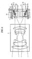
- Fig. 10 is a diagram showing a partial configuration of an embodiment 10 of the optical antenna in accordance with the present invention.
- Fig. 1 is a diagram showing a configuration of an embodiment 1 of the optical antenna in accordance with the present invention.
- optical fibers 1 and 2 of an optical transmitting and receiving section radiate laser beams (optical signals) to be transmitted from the optical transmitting and receiving section to an optical transmitting and receiving system 4, and receive laser beams focused by the optical transmitting and receiving system 4 and supply them to the optical transmitting and receiving section.
- An optical element mount 3 places fiber ends 1a and 2a of the optical fibers 1 and 2 at different positions on an image plane of the optical transmitting and receiving system 4.
- the optical element mount 3 constitutes an arrangement means.
- the optical transmitting and receiving system 4 consists of a transmission lens made from an imaging optical system such as a photographic objective, and transmits, when the fiber ends 1a and 2a of the optical fibers 1 and 2 radiate the laser beams, the laser beams to space by refracting them to spherical waves. In other words, the optical transmitting and receiving system 4 collimates the laser beams to parallel light rays toward the space. In addition, when laser beams arrive from the space, it focuses the laser beams onto the fiber ends 1a and 2a of the optical fibers 1 and 2.
- the optical transmitting and receiving system 4 is constructed such that the aberration becomes small enough at an image height above the optical axes of the optical fibers 1 and 2.
- the optical element mount 3 disposes the fiber ends 1a and 2a of the optical fibers 1 and 2 at two different positions on the image plane of the optical transmitting and receiving system 4.
- the optical transmitting and receiving system 4 collimates the laser beam to a parallel light ray, and emits the laser beam in the optical transmitting and receiving direction 5 toward the space.
- the optical transmitting and receiving system 4 collimates the laser beam into a parallel light ray, and emits the laser beam in the optical transmitting and receiving direction 6 toward the space.
- the optical transmitting and receiving system 4 focuses the laser beam onto the fiber end 1a of the optical fiber 1.
- the laser beam is launched into the fiber end 1a of the optical fiber 1 to be received by the optical transmitting and receiving section connected to the optical fiber 1.
- the optical transmitting and receiving system 4 focuses the laser beam onto the fiber end 2a of the optical fiber 2.
- the laser beam is launched into the fiber end 2a of the optical fiber 2 to be received by the optical transmitting and receiving section connected to the optical fiber 2.
- the focal length f of the optical transmitting and receiving system 4 is determined by the following expressions (1) and (2).
- D the diameter of the laser beam collimated by the optical transmitting and receiving system 4
- ⁇ the half angle of the angle of radiation of the laser beam radiated from the fiber ends 1a and 2a of the optical fibers 1 and 2.
- optical transmitting and receiving directions 5 and 6 are determined by the positions of the fiber ends 1a and 2a of the optical fibers 1 and 2.
- the present embodiment 1 is configured such that it includes the optical element mount 3 for disposing the fiber ends 1a and 2a of the optical fibers 1 and 2 at different positions, and the optical transmitting and receiving system 4 for collimating, when the laser beams are radiated from the fiber ends 1a and 2a, the laser beams to the parallel light rays toward the space, and for focusing, when the laser beams arrive from the space, the laser beams onto the fiber ends 1a and 2a.
- the optical element mount 3 for disposing the fiber ends 1a and 2a of the optical fibers 1 and 2 at different positions
- the optical transmitting and receiving system 4 for collimating, when the laser beams are radiated from the fiber ends 1a and 2a, the laser beams to the parallel light rays toward the space, and for focusing, when the laser beams arrive from the space, the laser beams onto the fiber ends 1a and 2a.
- the optical antenna need not install the complicated mechanical elements, it can reduce its size, weight and cost. In addition, since it does not use mechanical drive, it can increase the reproducibility of the optical transmitting and receiving directions.
- the optical element mount 3 disposes the fiber ends 1a and 2a of the optical fibers 1 and 2 constituting the optical transmitting and receiving section at different locations in the present embodiment 1, this is not essential.
- the optical element mount 3 can dispose light sources or photo-detectors constituting the optical transmitting and receiving section.
- the optical transmitting and receiving section carries out only one of the transmission and reception of the laser beams.
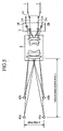
- Fig. 2 is a diagram showing a configuration of an embodiment 2 of the optical antenna in accordance with the present invention.
- Fig. 2 since the same reference numerals designate the same or like portions to those of Fig. 1 , their description will be omitted here.
- Optical fibers 11-15 of an optical transmitting and receiving section radiate laser beams to be transmitted from the optical transmitting and receiving section to the optical transmitting and receiving system 4. At the same time, the optical fibers 11-15 receive the laser beams focused by the optical transmitting and receiving system 4, and supply them to the optical transmitting and receiving section.
- Optical transmitting and receiving directions 21-25 are directions of the laser beams set by the optical antenna.
- the foregoing embodiment 1 is described by way of example in which the laser beams have fixed two directions as the optical transmitting and receiving directions.
- the optical element mount 3 disposes the fiber ends of three or more optical fibers, it is possible to set three or more directions as the optical transmitting and receiving directions of the laser beams.
- the optical element mount 3 has the fiber ends 11a-15a of five optical fibers 11-15 disposed thereon, thereby implementing five optical transmitting and receiving directions 21-25.
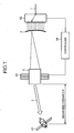
- Fig. 3 is a diagram showing a configuration of an embodiment 3 of the optical antenna in accordance with the present invention.
- the optical antenna of Fig. 3 is applied to a wind speed measuring LIDAR (Light Detection And Ranging) apparatus.
- LIDAR Light Detection And Ranging
- Optical transmitting and receiving sections 31 and 32 constitute an optical transmitting and receiving means for radiating outgoing laser beams toward the space, and for receiving incoming laser beams from the space.
- Laser light sources 33 of the optical transmitting and receiving sections 31 and 32 each emit a laser beam under the control of a controller 36.
- Optical path bifurcating sections 34 divide the optical fibers 1 and 2 into two branches each.
- Optical receivers 35 receive laser beams from the optical fibers 1 and 2, convert the laser beams into electric signals, and supply them to the controller 36, respectively.
- the controller 36 controls the driving of the laser light source 33, and measures the wind speed at measurement points 41 and 42 (object to be measured) by monitoring electric signals output from the optical receivers 35.
- the optical transmitting and receiving system 4 of Fig. 3 has a double Gaussian configuration.
- the controller 36 drives the laser light sources 33 of the optical transmitting and receiving sections 31 and 32 simultaneously.
- the laser light sources 33 of the optical transmitting and receiving sections 31 and 32 emit laser beams.
- the laser beams emitted from the laser light sources 33 are transmitted through the optical path bifurcating sections 34, and are radiated from the fiber ends 1a and 2a of the optical fibers 1 and 2 to the optical transmitting and receiving system 4.
- the optical transmitting and receiving system 4 collimates the laser beams to parallel light rays, and outputs the laser beams to the measurement points 41 and 42.
- the optical transmitting and receiving directions 5 and 6 of the laser beams output from the optical transmitting and receiving system 4 are determined by the arrangement of the fiber ends 1a and 2a on the optical element mount 3 as in the foregoing embodiment 1.
- the optical element mount 3 disposes the fiber ends 1a and 2a in such a manner that the laser beams are focused onto the measurement points 41 and 42.
- the optical transmitting and receiving system 4 since the optical transmitting and receiving system 4 carries out highly accurate aberration correction, the laser beams passing through the optical transmitting and receiving system 4 become highly accurate spherical waves.
- the laser beams focused onto the measurement points 41 and 42 are scattered by dusts at the measurement points 41 and 42 so that parts of the laser beams return to the optical transmitting and receiving system 4.
- the optical transmitting and receiving system 4 focuses the laser beam in the optical transmitting and receiving direction 5 onto the fiber end 1a of the optical fiber 1, and the laser beam in the optical transmitting and receiving direction 6 onto the fiber end 2a of the optical fiber 2.
- the laser beam in the optical transmitting and receiving direction 5 is launched into the fiber end 1a of the optical fiber 1, and reaches the optical receiver 35 via the optical path bifurcating section 34.
- the laser beam in the optical transmitting and receiving direction 6 is launched into the fiber end 2a of the optical fiber 2, and reaches the optical receiver 35 via the optical path bifurcating section 34.
- the optical receivers 35 of the optical transmitting and receiving sections 31 and 32 convert the laser beams to electric signals and supply them to the controller 36.
- the controller 36 measures the wind speeds of the measurement points 41 and 42 by monitoring the electric signals.
- the present embodiment 3 can set the two optical transmitting and receiving directions 5 and 6 without installing the complicated mechanical elements as in the foregoing embodiment 1.
- it offers an advantage of being able to measure the wind speeds in the two directions without increasing the weight or cost.
- the present embodiment 3 is described by way of example that measures the wind speeds in two directions, this is not essential.
- the optical element mount 3 disposes fiber ends of three or more optical fibers thereon as in the foregoing embodiment 2, it can measure the wind speeds in three or more directions.
- the controller 36 can appropriately drive one of the optical receiver 35 of the optical transmitting and receiving section 31 and the optical receiver 35 of the optical transmitting and receiving section 32 on an as needed basis.
- Fig. 4 is a diagram showing a configuration of an embodiment 4 of the optical antenna in accordance with the present invention.
- Fig. 4 since the same reference numerals designate the same or like portions to those of Fig. 3 , their description will be omitted here.
- Rectilinear rails 51 have their moving components fixing the optical fibers 1 and 2, and their guides fixed to the optical element mount 3.
- a moving plate 53 is supported by rods 54 via bearings, and moves in the direction along the rods 54 when driven by a rectilinear actuator 52.
- the rectilinear rails 51, rectilinear actuator 52, moving plate 53 and rods 54 constitute a driving mechanism for changing the positions of the fiber ends 1a and 2a.
- the distance between the lens and dry plate is adjusted to bring the subject into focus.
- the amount of the shift can be calculated if the distance of the subject is known.
- the present embodiment 4 controls the measured distance S and the positions of the fiber ends 1a and 2a such that they match the image forming relation.
- controlling the rectilinear actuator 52 enables the moving plate 53 to shift in the direction along the rods 54, and the contact of the moving plate 53 with the moving components of the rectilinear rails 51 enables the fiber ends 1a and 2a to shift their positions in the directions along the guides of the rectilinear rails 51.
- the present embodiment 4 makes it possible not only to set the optical transmitting and receiving directions to any desired directions, but also to change the distance to the measurement points. Accordingly, it offers an advantage of being able to increase the flexibility of the measurement points.
- Fig. 5 is a diagram showing a configuration of an embodiment 5 of the optical antenna in accordance with the present invention.
- Fig. 5 since the same reference numerals designate the same or like portions to those of Fig. 3 , their description will be omitted here.
- optical device switching section 61 connects, when measuring the wind speeds at far measurement points 41a and 42a, the optical fibers 1 and 2 to optical fibers 1A and 2A, respectively, and connects, when measuring the wind speeds at near measurement points 41b and 42b, the optical fibers 1 and 2 to optical fibers 1B and 2B, respectively.
- the optical device switching section 61 constitutes a selecting means.
- the driving mechanism installed can results in an increase in weight and cost.
- the spacing between two measurement points to be measured simultaneously varies in proportion to the measured distance S. In the measurement of the wind speed, the variation in the spacing between the measurement points can cause a measurement error.
- the optical antenna will be described which can vary the measured distance S without using the driving mechanism, and maintain the spacing between the two measurement points independently of the measured distance S.
- the optical element mount 3 disposes the fiber ends of the optical fibers 1A and 2A in such a manner that the laser beams radiated from the optical transmitting and receiving system 4 are focused onto the far measurement points 41a and 42a, and disposes the fiber ends of the optical fibers 1B and 2B in such a manner that the laser beams radiated from the optical transmitting and receiving system 4 are focused onto the near measurement points 41b and 42b.
- the optical device switching section 61 connects, when measuring the wind speeds at the far measurement points 41a and 42a, the optical fibers 1 and 2 to the optical fibers 1A and 2A, respectively, and connects, when measuring the wind speeds at near measurement points 41b and 42b, the optical fibers 1 and 2 to the optical fibers 1B and 2B, respectively.
- the present embodiment 5 can set the optical transmitting and receiving directions at desired directions, and vary the distances to the measurement points. Thus, it offers an advantage of being able to increase the flexibility of the measurement points.
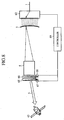
- Fig. 6 is a diagram showing a configuration of an embodiment 6 of the optical antenna in accordance with the present invention.
- Fig. 6 since the same reference numerals designate the same or like portions to those of Fig. 3 , their description will be omitted here.
- the optical device switching section 62 constitutes a selecting means.
- the foregoing embodiment 5 is described by way of example in which the optical device switching section 61 switches the connection targets of the optical fibers 1 and 2 when changing the distance to the measurement point.
- the optical device switching section 62 switches the connection target of the optical fiber 1 in such a manner that the optical transmitting and receiving direction 5 agrees with the angle looking at the moving target 43.
- the present embodiment 6 can capture the moving target 43 whenever necessary without the driving mechanism. Accordingly, it offers an advantage of being able to reduce the weight and cost of the apparatus. In addition, since it has no time lag depending on the positioning time of the driving mechanism, it offers an advantage of being able to continually trace the moving target 43 even if the moving target 43 moves at high speed.
- Fig. 7 is a diagram showing a configuration of an embodiment 7 of the optical antenna in accordance with the present invention.
- Fig. 7 since the same reference numerals designate the same or like portions to those of Fig. 6 , their description will be omitted here.
- a controller 64 controls at least one of the optical device switching section 62 and a rectilinear stage 63 in response to the changes in the position of the moving target 43 to enable the transmitting and receiving optical system 4 to vary its position or angle.
- the controller 64 and rectilinear stage 63 constitute the selecting means.
- the foregoing embodiment 6 is described by way of example in which the optical device switching section 62 switches the connection target of the optical fiber 1 in such a manner that the optical transmitting and receiving direction 5 agrees with the angle looking at the moving target 43.
- the density of the optical fibers n (the spacings between them) that can be mounted on the optical element mount 3 is physically limited, it is unavoidable that the angle of the optical transmitting and receiving direction 5 becomes discrete. Accordingly, as the distance to the moving target 43 increases, the time period that prevents the measurement increases, so that the probability of losing track of the moving target 43 increases.
- the present embodiment 7 is designed such that it can reduce the probability of losing track of the moving target 43 by reducing the duration that prevents the measurement even through the moving target 43 is placed at a distance.
- the controller 64 controls the optical device switching section 62 so as to switch the connection target of the optical fiber 1 as in the foregoing embodiment 6.
- the controller 64 controls the rectilinear stage 63 to move the optical transmitting and receiving system 4 by a minute amount (to move by an amount corresponding to an angle smaller than the pitch of the angle of the optical transmitting and receiving direction 5 due to the switching of the optical fibers n), thereby tracking the moving target 43.
- the optical device switching section 62 switches the connection target of the optical fiber 1 to the adjacent optical fiber n-1 (or n+1), and returns the rectilinear stage 63 to its original position.
- the present embodiment 7 offers an advantage of being able to reduce the probability of losing track of the moving target 43 by reducing the time period which prevents the measurement even if the moving target 43 is at a considerable distance.
- the present embodiment 7 requires the driving mechanism, the control of the rectilinear stage 63 is only for the purpose of making up for the control of the optical transmitting and receiving direction 5 by the optical device switching section 62. Accordingly, the range of carrying out the driving control is much smaller than that of the conventional apparatus, and hence the present embodiment 7 has little influence on the weight and cost.
- Fig. 8 is a diagram showing a configuration of an embodiment 8 of the optical antenna in accordance with the present invention.
- Fig. 8 since the same reference numerals designate the same or like portions to those of Fig. 6 , their description will be omitted here.
- Stepping motors 67 and 68 carry out rotation driving of wedge prisms 65 and 66, which are installed on the moving target 43 side of the optical transmitting and receiving system 4, under instructions from the controller 69.
- the controller 69 controls the stepping motors 67 and 68 in accordance with the changes in the position of the moving target 43.
- the steppingmotors 67 and 68 and controller 69 constitute the selecting means.
- the foregoing embodiment 7 is described by way of example in which the controller 64 controls the rectilinear stage 63 appropriately to compensate for the control resolution limitations of the optical transmitting and receiving direction 5 by the optical device switching section 62.
- the controller 69 controls the stepping motors 67 and 68 in accordance with the changes in the position of the moving target 43 to adjust the angles of refraction of the laser beams with the wedge prisms 65 and 66, thereby making fine adjustment of the optical transmitting and receiving direction 5.
- the configuration offers the similar advantage as that of the foregoing embodiment 7.
- the present embodiment 8 requires the driving mechanism, the control of the stepping motors 67 and 68 is only for the purpose of making up for the control of the optical transmitting and receiving direction 5 by the optical device switching section 62. Accordingly, the range of carrying out the driving control is much smaller than that of the conventional apparatus, and hence the present embodiment 8 has little influence on the weight and cost.
- Fig. 9 is a diagram showing a configuration of an embodiment 9 of the optical antenna in accordance with the present invention.
- Fig. 9 since the same reference numerals designate the same or like portions to those of Fig. 6 , their description will be omitted here.
- a casing 70 fixes and supports the optical transmitting and receiving system 4 and the optical element mount 3, and a dual-axis gimbal driving mechanism 71 varies the installation angle of the casing 70 under the instructions from the controller 72.
- the controller 72 controls the dual-axis gimbal driving mechanism 71 in response to the position changes of the moving target 43.
- the dual-axis gimbal driving mechanism 71 and the controller 72 constitute the selecting means.
- the foregoing embodiment 7 is described by way of example in which the controller 64 controls the rectilinear stage 63 appropriately to compensate for the control resolution limitations of the optical transmitting and receiving direction 5 by the optical device switching section 62.
- the controller 72 controls the dual-axis gimbal driving mechanism 71 in accordance with the changes in the position of the moving target 43 to vary the installation angle of the casing 70, thereby making fine adjustment of the optical transmitting and receiving direction 5.
- the configuration offers the similar advantage as that of the foregoing embodiment 7.
- the control of the dual-axis gimbal driving mechanism 71 is only for the purpose of making up for the control of the optical transmitting and receiving direction 5 by the optical device switching section 62. Accordingly, the range of carrying out the driving control is much smaller than that of the conventional apparatus, and hence the present embodiment 9 has little influence on the weight and cost.
- Fig. 10 is a diagram showing a configuration of an embodiment 10 of the optical antenna in accordance with the present invention.
- Fig. 10 since the same reference numerals designate the same or like portions to those of Fig. 3 , their description will be omitted here.
- the reference numeral 85 designates the image plane of the optical transmitting and receiving system 4; and reference numerals 86 and 87 each designate a focus of the optical transmitting and receiving system 4.
- the optical antenna to measure the measurement points 41 and 42 at a considerable distance.
- the transmitting and receiving optical system 4 is required which can transmit and receive the laser beams with a diameter of about 100 mm. Accordingly, a commercially available imaging optical system is not always applicable, which can require specific design and increase the cost of manufacturing.
- the diameter of the lenses is nearly twice the diameter of the laser beams to be transmitted and received, which presents a problem of weight and size.
- the present embodiment 10 tries to reduce the size and weight of the transmitting and receiving optical systems 4 used in the foregoing embodiments 1-9.
- the optical transmitting and receiving system 4 of Fig. 10 is configured such that it carries out the measurement under the following conditions.
- the optical transmitting and receiving system 4 is designed by removing the following restrictions as compared with the photographic objective.
- the optical transmitting and receiving system 4 includes four lenses, and their diameter is limited to 1.35 or less times the diameter of the laser beam. Thus, it can implement a compact, lightweight and low cost apparatus.
- the present embodiment can facilitate manufacturing, and implement low cost.
- the optical antenna in accordance with the present invention is suitable for LIDAR apparatuses and optical communication systems which must reduce cost, size and weight for transmitting and receiving laser beams to and from the space.
Landscapes
- Physics & Mathematics (AREA)
- General Physics & Mathematics (AREA)
- Optics & Photonics (AREA)
- Astronomy & Astrophysics (AREA)
- Electromagnetism (AREA)
- Engineering & Computer Science (AREA)
- Computer Networks & Wireless Communication (AREA)
- Signal Processing (AREA)
- Optical Radar Systems And Details Thereof (AREA)
- Optical Communication System (AREA)
- Optical Couplings Of Light Guides (AREA)
- Variable-Direction Aerials And Aerial Arrays (AREA)
Claims (9)
- Eine optische Antenne, die umfasst:eine Mehrzahl von optischen Übertragungs- und Empfangsmitteln (1a, 2a) ausgebildet zum Ausstrahlen eines abgehenden optischen Signals in den Raum und ausgebildet zum Empfangen eines eingehenden optischen Signals aus dem Raum;ein Mittel zum Anordnen (3) zum Installieren besagter Mehrzahl von optischen Übertragungs- und Empfangsmitteln (1a, 2a) an unterschiedlichen Positionen auf besagtem Mittel zum Anordnen; undein optisches System (4) zum Übertragen, wenn das optische Signal von besagten optischen Übertragungs- und Empfangsmitteln (1a, 2a) ausgestrahlt wird, des optischen Signals in den Raum durch Kollimieren des optischen Signals zu einem parallelen Strahl, und zum Fokussieren, wenn das optische Signal aus dem Raum ankommt, des optischen Signals auf besagte optische Übertragungs- und Empfangsmittel (1a, 2a);dadurch gekennzeichnet, dass
das optische System (4) eine erste Linse (81), die positive Brechkraft hat, eine zweite Linse (82), die negative Brechkraft hat, eine dritte Linse (83), die positive Brechkraft hat, und eine vierte Linse (84), die positive Brechkraft hat, umfasst, und wobei besagte erste Linse (81), besagte zweite Linse (82), besagte dritte Linse (83) und besagte vierte Linse (84) in dieser Anordnung von einer Seite des optischen Systems (4) angeordnet sind, auf der ein Objekt, das durch Senden besagten optischen Signals zu und Empfangen besagten optischen Signals von ihm zu messen ist, zu positionieren ist. - Die optische Antenne gemäß Anspruch 1, darüber hinaus umfassend ein Steuermittel (36) zum simultanen Ansteuern besagter Mehrzahl von optischen Übertragungs- und Empfangsmitteln (1a, 2a).
- Die optische Antenne gemäß Anspruch 1, darüber hinaus umfassend ein Steuermittel (36) zum Ansteuern jeglicher gewünschter optischer Übertragungs- und Empfangsmittel besagter Mehrzahl von optischen Übertragungs- und Empfangsmitteln (1a, 2a).
- Die optische Antenne gemäß Anspruch 1, darüber hinaus umfassend einen Antriebsmechanismus (51-54), um die Positionen besagter, auf besagtem Mittel zum Anordnen (3) installierter optischer Übertragungs- und Empfangsmittel (1a, 2a) variabel zu gestalten.
- Die optische Antenne gemäß Anspruch 1, darüber hinaus umfassend ein Auswahlmittel (61, 62) zum Auswählen einer gewünschten optischen Faser aus einer Mehrzahl von auf besagtem Mittel zum Anordnen (3) als Komponenten der optischen Übertragungs- und Empfangsmittel installierten optischen Fasern (1, 2) und zum Verbinden der ausgewählten optischen Faser mit besagten optischen Übertragungs- und Empfangsmitteln (1a, 2a).
- Die optische Antenne gemäß Anspruch 5, wobei besagtes Auswahlmittel (61, 62) ausgebildet ist zur Auswahl einer optischen Faser, die an einer Position zum Ausstrahlen eines Lichtsignals an eine Position eines zu messenden Objekts angeordnet ist.
- Die optische Antenne gemäß Anspruch 6, wobei besagtes Auswahlmittel (61, 62) ausgebildet ist, um eine Position oder einen Winkel besagten optischen Systems (4) in Reaktion auf Änderungen in einer Position des zu messenden Objects (43) variabel zu gestalten.
- Die optische Antenne gemäß Anspruch 6, wobei ein Keilprisma (65, 66) auf der Seite des optischen Systems bei dem zu messenden Objekt installiert ist und wobei besagtes Auswahlmittel (61, 62) ausgebildet ist zum Rotieren des Keilprismas (65, 66) in Reaktion auf Änderungen in einer Position des zu messenden Objektes (43).
- Die optische Antenne gemäß Anspruch 6, wobei besagtes Auswahlmittel (61, 62) ausgebildet ist zum Durchführen eines kardanischen Antreibens besagten optischen Systems (4) und Mittels zum Anordnen (4) in Reaktion auf Änderungen in einer Position des zu messenden Objekts (43).
Applications Claiming Priority (1)
| Application Number | Priority Date | Filing Date | Title |
|---|---|---|---|
| PCT/JP2003/001034 WO2004068746A1 (ja) | 2003-01-31 | 2003-01-31 | 光アンテナ |
Publications (4)
| Publication Number | Publication Date |
|---|---|
| EP1589678A1 EP1589678A1 (de) | 2005-10-26 |
| EP1589678A4 EP1589678A4 (de) | 2008-06-11 |
| EP1589678B1 true EP1589678B1 (de) | 2013-03-27 |
| EP1589678B8 EP1589678B8 (de) | 2013-06-19 |
Family
ID=32800849
Family Applications (1)
| Application Number | Title | Priority Date | Filing Date |
|---|---|---|---|
| EP03815597.4A Expired - Lifetime EP1589678B8 (de) | 2003-01-31 | 2003-01-31 | Optische antenne |
Country Status (5)
| Country | Link |
|---|---|
| US (1) | US7151882B2 (de) |
| EP (1) | EP1589678B8 (de) |
| JP (1) | JPWO2004068746A1 (de) |
| DK (1) | DK1589678T3 (de) |
| WO (1) | WO2004068746A1 (de) |
Families Citing this family (19)
| Publication number | Priority date | Publication date | Assignee | Title |
|---|---|---|---|---|
| JP4701454B2 (ja) * | 2005-05-26 | 2011-06-15 | 独立行政法人情報通信研究機構 | 空間光通信方法および空間光通信装置 |
| US7286730B2 (en) * | 2006-03-15 | 2007-10-23 | Avanex Corporation | Optical switch having angle tuning elements and multiple-fiber collimators |
| US8493445B2 (en) * | 2006-05-31 | 2013-07-23 | Sigma Space Corp | Scanner/optical system for three-dimensional lidar imaging and polarimetry |
| US7689076B1 (en) | 2009-02-20 | 2010-03-30 | The Boeing Company | Optical communications system and method for optimizing an optical communications system |
| KR101600908B1 (ko) * | 2009-08-21 | 2016-03-09 | 삼성전자주식회사 | 고속 패킷 억세스 시스템에서 잔류 이득 제어를 통한 신호대잡음비 측정 방법 및 이를 위한 장치 |
| CN101707502B (zh) * | 2009-11-13 | 2012-07-18 | 南京邮电大学 | 无线通信光接收天线 |
| DE102010035703A1 (de) * | 2010-08-27 | 2012-03-01 | Repower Systems Ag | IR-Gefahrenfeuer |
| CN102571204B (zh) * | 2011-12-09 | 2015-08-12 | 西安电子科技大学 | 光发射天线系统及其波束控制方法 |
| US8917997B2 (en) * | 2012-10-05 | 2014-12-23 | Applied Micro Circuits Corporation | Collimated beam channel with four lens optical surfaces |
| US9723386B1 (en) * | 2014-05-05 | 2017-08-01 | Google Inc. | Communication device |
| US10884105B2 (en) | 2018-05-31 | 2021-01-05 | Eagle Technology, Llc | Optical system including an optical body with waveguides aligned along an imaginary curved surface for enhanced beam steering and related methods |
| EP3891906A1 (de) * | 2018-07-19 | 2021-10-13 | Abderhamane, Ahmad | Mobiles endgerät und zellulares netzwerk mit photonischen antennen und pseudo-satelliten zur erhöhung der übertragungsraten und zur verringerung des risikos einer gehirnerkrankung und der elektromagnetischen hf-verunreinigung |
| CN109391326A (zh) * | 2018-11-30 | 2019-02-26 | 宁波光舟通信技术有限公司 | 一种机载收发系统 |
| US11777603B2 (en) * | 2019-01-16 | 2023-10-03 | X Development Llc | High magnification afocal telescope with high index field curvature corrector |
| WO2020208896A1 (ja) | 2019-04-08 | 2020-10-15 | 三菱電機株式会社 | 風計測ライダ装置 |
| CN113631958A (zh) | 2019-04-08 | 2021-11-09 | 三菱电机株式会社 | 测风激光雷达装置 |
| CN110233666A (zh) * | 2019-06-06 | 2019-09-13 | 长春理工大学 | 一种基于双凸面反射镜组的多点激光通信用光学天线 |
| US11411647B2 (en) * | 2020-01-31 | 2022-08-09 | Com Dev Ltd. | Coarse pointing arrangement |
| CN113746547B (zh) * | 2021-08-13 | 2023-08-22 | 长春理工大学 | 一种基于液晶光栅和单摆镜的一对二激光通信装置及方法 |
Family Cites Families (13)
| Publication number | Priority date | Publication date | Assignee | Title |
|---|---|---|---|---|
| JPS5985150A (ja) | 1982-11-08 | 1984-05-17 | Hitachi Ltd | 移動体制御用光通信装置 |
| JPS6198033A (ja) | 1984-10-19 | 1986-05-16 | Hitachi Ltd | 移動体用光無線装置 |
| JPS6395742A (ja) | 1986-10-13 | 1988-04-26 | Canon Inc | 光受信器 |
| JP3034565B2 (ja) | 1990-08-06 | 2000-04-17 | リコー光学株式会社 | テレセントリックなfθレンズ |
| JPH0865031A (ja) | 1994-08-26 | 1996-03-08 | Fujitsu Denso Ltd | 光通信アンテナの指向性調整装置 |
| JPH0964821A (ja) | 1995-08-23 | 1997-03-07 | Totoku Electric Co Ltd | 空間伝送光通信装置 |
| JP3859335B2 (ja) | 1996-12-17 | 2006-12-20 | Nec東芝スペースシステム株式会社 | 光通信装置および光通信システム |
| DE59800284D1 (de) | 1997-10-01 | 2000-11-02 | Contraves Space Ag Zuerich | Verfahren und Anordnung zur Optimierung von optischen Intersatellitenverbindungen |
| JP3169074B2 (ja) * | 1998-09-25 | 2001-05-21 | 日本電気株式会社 | レーザレーダ装置 |
| EP1130810A2 (de) * | 2000-02-21 | 2001-09-05 | TRW Inc. | Gemeinsames optisches Erfassungs- und Verfolgungssatellitensystem |
| JP2001285203A (ja) | 2000-03-30 | 2001-10-12 | Fuchu Giken:Kk | 複数の集光ホーンを使用した光受信装置 |
| US6522437B2 (en) | 2001-02-15 | 2003-02-18 | Harris Corporation | Agile multi-beam free-space optical communication apparatus |
| JP3258997B1 (ja) * | 2001-05-15 | 2002-02-18 | 株式会社 総合開発事務所 | 光受信器及びそれを用いた光通信システム、並びに光通信方法 |
-
2003
- 2003-01-31 JP JP2004567556A patent/JPWO2004068746A1/ja active Pending
- 2003-01-31 US US10/532,811 patent/US7151882B2/en not_active Expired - Fee Related
- 2003-01-31 WO PCT/JP2003/001034 patent/WO2004068746A1/ja not_active Ceased
- 2003-01-31 DK DK03815597.4T patent/DK1589678T3/da active
- 2003-01-31 EP EP03815597.4A patent/EP1589678B8/de not_active Expired - Lifetime
Also Published As
| Publication number | Publication date |
|---|---|
| EP1589678A4 (de) | 2008-06-11 |
| EP1589678B8 (de) | 2013-06-19 |
| WO2004068746A1 (ja) | 2004-08-12 |
| US20060008238A1 (en) | 2006-01-12 |
| US7151882B2 (en) | 2006-12-19 |
| DK1589678T3 (da) | 2013-05-27 |
| JPWO2004068746A1 (ja) | 2006-05-25 |
| EP1589678A1 (de) | 2005-10-26 |
Similar Documents
| Publication | Publication Date | Title |
|---|---|---|
| EP1589678B1 (de) | Optische antenne | |
| CN110488247B (zh) | 一种二维mems扫描振镜激光雷达系统 | |
| CN107544138B (zh) | 远程LiDAR系统和用于补偿扫描仪运动的影响的方法 | |
| EP3851878A1 (de) | Lasermessmodul und laserradar | |
| US5005934A (en) | Fiber optics channel selection device | |
| US10788574B2 (en) | LIDAR device and LIDAR system including the same | |
| CN112204427B (zh) | 一种测距装置及移动平台 | |
| JPH069396B2 (ja) | 光ファイバー通信交換装置 | |
| KR101951242B1 (ko) | 라이다 장치 및 이를 포함하는 라이다 시스템 | |
| CN109444850B (zh) | 相控阵激光雷达 | |
| TW202018367A (zh) | 級聯鏡列及包含其之掃描系統 | |
| CN114779269B (zh) | 棱镜模块、激光雷达光学系统及调频连续波激光雷达 | |
| EP3752854B1 (de) | Kompakter testbereich für aktive optische zieldetektoren | |
| CN109444851B (zh) | 激光发射机构及相控阵激光雷达 | |
| CN115275608A (zh) | 一种光相控阵宽角扫描测试系统和方法 | |
| JP2001203641A (ja) | 空間光伝送装置 | |
| CN116661016B (zh) | 一种非复合轴光电跟踪机构及其控制方法 | |
| US7058254B2 (en) | Optical device, optical path switching device and optical path switching method | |
| JP2007010636A (ja) | レーザ測距装置 | |
| RU2272358C1 (ru) | Устройство двусторонней оптической связи | |
| JP2858488B2 (ja) | 光 源 | |
| RU2785768C1 (ru) | Система формирования и наведения лазерного излучения излучателей с оптоволоконными выводами на цель | |
| RU2805284C1 (ru) | Способ динамического контроля соосности пеленгационных и лазерных каналов | |
| RU2793613C1 (ru) | Система формирования и наведения лазерного излучения излучателей с оптоволоконными выводами на цель | |
| US20240402305A1 (en) | Compact LiDAR Sensor |
Legal Events
| Date | Code | Title | Description |
|---|---|---|---|
| PUAI | Public reference made under article 153(3) epc to a published international application that has entered the european phase |
Free format text: ORIGINAL CODE: 0009012 |
|
| 17P | Request for examination filed |
Effective date: 20050704 |
|
| AK | Designated contracting states |
Kind code of ref document: A1 Designated state(s): AT BE BG CH CY CZ DE DK EE ES FI FR GB GR HU IE IT LI LU MC NL PT SE SI SK TR |
|
| RAP1 | Party data changed (applicant data changed or rights of an application transferred) |
Owner name: MITSUBISHI DENKI KABUSHIKI KAISHA |
|
| RBV | Designated contracting states (corrected) |
Designated state(s): DE DK FR GB |
|
| A4 | Supplementary search report drawn up and despatched |
Effective date: 20080515 |
|
| 17Q | First examination report despatched |
Effective date: 20090323 |
|
| GRAP | Despatch of communication of intention to grant a patent |
Free format text: ORIGINAL CODE: EPIDOSNIGR1 |
|
| RIN1 | Information on inventor provided before grant (corrected) |
Inventor name: SUZUKI, J., C/O MITSUBISHI DENKI KABUSHIKI KAISHA Inventor name: ANDO, TOSHIYUKI, C/O MITSUBISHI DENKI KABUSHIKI KA Inventor name: HIRANO, YOSHIHITO, C/O MITSUBISHI DENKI KABUSHIKI Inventor name: TAMAGAWA, YASUHISA, C/O MITSUBISHI DENKI KABUSHIKI |
|
| GRAS | Grant fee paid |
Free format text: ORIGINAL CODE: EPIDOSNIGR3 |
|
| REG | Reference to a national code |
Ref country code: DE Ref legal event code: R079 Ref document number: 60343637 Country of ref document: DE Free format text: PREVIOUS MAIN CLASS: H04B0010105000 Ipc: H04B0010118000 |
|
| GRAA | (expected) grant |
Free format text: ORIGINAL CODE: 0009210 |
|
| AK | Designated contracting states |
Kind code of ref document: B1 Designated state(s): DE DK FR GB |
|
| REG | Reference to a national code |
Ref country code: GB Ref legal event code: FG4D |
|
| RIC1 | Information provided on ipc code assigned before grant |
Ipc: G02B 6/32 20060101ALI20130219BHEP Ipc: H04B 10/118 20130101AFI20130219BHEP |
|
| REG | Reference to a national code |
Ref country code: DE Ref legal event code: R096 Ref document number: 60343637 Country of ref document: DE Effective date: 20130523 |
|
| REG | Reference to a national code |
Ref country code: DK Ref legal event code: T3 |
|
| RIN2 | Information on inventor provided after grant (corrected) |
Inventor name: TAMAGAWA, YASUHISA, C/O MITSUBISHI DENKI KABUSHIKI Inventor name: HIRANO, YOSHIHITO, C/O MITSUBISHI DENKI KABUSHIKI Inventor name: SUZUKI, JIRO, C/O MITSUBISHI DENKI KABUSHIKI KAISH Inventor name: ANDO, TOSHIYUKI, C/O MITSUBISHI DENKI KABUSHIKI KA |
|
| PLBE | No opposition filed within time limit |
Free format text: ORIGINAL CODE: 0009261 |
|
| STAA | Information on the status of an ep patent application or granted ep patent |
Free format text: STATUS: NO OPPOSITION FILED WITHIN TIME LIMIT |
|
| 26N | No opposition filed |
Effective date: 20140103 |
|
| REG | Reference to a national code |
Ref country code: DE Ref legal event code: R097 Ref document number: 60343637 Country of ref document: DE Effective date: 20140103 |
|
| REG | Reference to a national code |
Ref country code: DE Ref legal event code: R084 Ref document number: 60343637 Country of ref document: DE |
|
| REG | Reference to a national code |
Ref country code: GB Ref legal event code: 746 Effective date: 20141029 |
|
| REG | Reference to a national code |
Ref country code: DE Ref legal event code: R084 Ref document number: 60343637 Country of ref document: DE Effective date: 20141107 |
|
| REG | Reference to a national code |
Ref country code: FR Ref legal event code: PLFP Year of fee payment: 14 |
|
| REG | Reference to a national code |
Ref country code: FR Ref legal event code: PLFP Year of fee payment: 15 |
|
| PGFP | Annual fee paid to national office [announced via postgrant information from national office to epo] |
Ref country code: FR Payment date: 20161215 Year of fee payment: 15 |
|
| PGFP | Annual fee paid to national office [announced via postgrant information from national office to epo] |
Ref country code: DE Payment date: 20170125 Year of fee payment: 15 |
|
| PGFP | Annual fee paid to national office [announced via postgrant information from national office to epo] |
Ref country code: DK Payment date: 20170110 Year of fee payment: 15 Ref country code: GB Payment date: 20170125 Year of fee payment: 15 |
|
| REG | Reference to a national code |
Ref country code: DE Ref legal event code: R119 Ref document number: 60343637 Country of ref document: DE |
|
| REG | Reference to a national code |
Ref country code: DK Ref legal event code: EBP Effective date: 20180131 |
|
| GBPC | Gb: european patent ceased through non-payment of renewal fee |
Effective date: 20180131 |
|
| PG25 | Lapsed in a contracting state [announced via postgrant information from national office to epo] |
Ref country code: DE Free format text: LAPSE BECAUSE OF NON-PAYMENT OF DUE FEES Effective date: 20180801 Ref country code: FR Free format text: LAPSE BECAUSE OF NON-PAYMENT OF DUE FEES Effective date: 20180131 |
|
| REG | Reference to a national code |
Ref country code: FR Ref legal event code: ST Effective date: 20180928 |
|
| PG25 | Lapsed in a contracting state [announced via postgrant information from national office to epo] |
Ref country code: GB Free format text: LAPSE BECAUSE OF NON-PAYMENT OF DUE FEES Effective date: 20180131 |
|
| PG25 | Lapsed in a contracting state [announced via postgrant information from national office to epo] |
Ref country code: DK Free format text: LAPSE BECAUSE OF NON-PAYMENT OF DUE FEES Effective date: 20180131 |