EP1589666B1 - Verfahren zur Korrektur der automatischen Leistungsregelungsfunktion eines Mobiltelefons und System dafür - Google Patents
Verfahren zur Korrektur der automatischen Leistungsregelungsfunktion eines Mobiltelefons und System dafür Download PDFInfo
- Publication number
- EP1589666B1 EP1589666B1 EP20040009223 EP04009223A EP1589666B1 EP 1589666 B1 EP1589666 B1 EP 1589666B1 EP 20040009223 EP20040009223 EP 20040009223 EP 04009223 A EP04009223 A EP 04009223A EP 1589666 B1 EP1589666 B1 EP 1589666B1
- Authority
- EP
- European Patent Office
- Prior art keywords
- dac control
- output power
- dac
- mobile telephone
- control value
- Prior art date
- Legal status (The legal status is an assumption and is not a legal conclusion. Google has not performed a legal analysis and makes no representation as to the accuracy of the status listed.)
- Expired - Lifetime
Links
- 238000012937 correction Methods 0.000 title claims description 79
- 238000000034 method Methods 0.000 title claims description 38
- 238000012360 testing method Methods 0.000 claims description 39
- 238000005259 measurement Methods 0.000 claims description 20
- 238000004891 communication Methods 0.000 claims description 11
- 238000006243 chemical reaction Methods 0.000 claims description 6
- 238000004519 manufacturing process Methods 0.000 description 12
- 238000013100 final test Methods 0.000 description 6
- 238000010586 diagram Methods 0.000 description 4
- 238000012986 modification Methods 0.000 description 2
- 230000004048 modification Effects 0.000 description 2
- 238000007796 conventional method Methods 0.000 description 1
- 238000013213 extrapolation Methods 0.000 description 1
Images


Classifications
-
- H—ELECTRICITY
- H03—ELECTRONIC CIRCUITRY
- H03G—CONTROL OF AMPLIFICATION
- H03G3/00—Gain control in amplifiers or frequency changers
- H03G3/20—Automatic control
- H03G3/30—Automatic control in amplifiers having semiconductor devices
- H03G3/3036—Automatic control in amplifiers having semiconductor devices in high-frequency amplifiers or in frequency-changers
- H03G3/3042—Automatic control in amplifiers having semiconductor devices in high-frequency amplifiers or in frequency-changers in modulators, frequency-changers, transmitters or power amplifiers
- H03G3/3047—Automatic control in amplifiers having semiconductor devices in high-frequency amplifiers or in frequency-changers in modulators, frequency-changers, transmitters or power amplifiers for intermittent signals, e.g. burst signals
-
- H—ELECTRICITY
- H04—ELECTRIC COMMUNICATION TECHNIQUE
- H04B—TRANSMISSION
- H04B1/00—Details of transmission systems, not covered by a single one of groups H04B3/00 - H04B13/00; Details of transmission systems not characterised by the medium used for transmission
- H04B1/02—Transmitters
- H04B1/04—Circuits
- H04B2001/0408—Circuits with power amplifiers
- H04B2001/0416—Circuits with power amplifiers having gain or transmission power control
Definitions
- the invention relates to a correction method and a correction system, and more particularly to a method for correcting a mobile telephone having an automatic power control function and a correction system therefor.
- FIG. 1 is a schematic illustration showing a conventional production line 100 for performing a radio frequency (RF) correction.
- the production and correction flows for typical mobile telephones are as follows. First, a main component of a mobile telephone, which includes a device under test (DUT) such as an RF antenna, is mounted to a circuit board in a circuit board component disposing stage 102. Then, in an RF correction stage 104, the output power of the RF antenna is corrected. If the output power of the RF antenna does not satisfy the communication specification such as the ETSI (European Telecommunications Standards Institute) power control specification, the circuit board is transferred to an RF repair/fine tuning stage 108 outside the production line 100.
- DUT device under test
- ETSI European Telecommunications Standards Institute
- the circuit board is transferred to an RF final test stage 106.
- the circuit board is repaired, and the output power of the RF antenna is finely tuned. If the repair succeeds, the circuit board is transferred to the RF final test stage 106; or otherwise, the circuit board is categorized as a defected part.
- the circuit board is first assembled in the mobile telephone, and the overall mobile telephone is then subjected to a final test. If the mobile telephone passes the final test, the mobile telephone is categorized as a good product, or otherwise as a defected product.
- each TDMA (Time Division Multiple Access) code frame is divided into several time slots, each of which is referred to as a burst.
- FIG. 2A is a graph showing a relationship between a power of the burst with respect to time. As shown in FIG. 2A , each burst may be divided into three portions including a ramp up portion 202, a burst portion 204 and a ramp down portion 206. In ETSI, the power of the burst portion 204 may have 32 power levels, which are controlled by 32 power control levels, respectively.
- FIG. 2B shows a look-up table created according to 32 power control levels and the normal output powers of the mobile telephone in the GSM400/GSM900/GSM850 system.
- the normal tolerances and extreme tolerances of the normal output powers are further illustrated.
- the base transceiver station momentarily commands the mobile telephone to automatically adjust the emitting power of the radio signal thereof according to the condition of the received radio signal. That is, the mobile telephone automatically selects different power control levels to generate a proper output power for communication with the base transceiver station according to the distance from the base transceiver station to the mobile telephone.
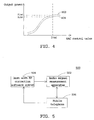
- FIG. 3 is a block diagram showing a portion of the system of the mobile telephone for generating the burst of FIG. 2A .
- the random access memory (RAM) 302 has stored multiple sets of words.
- a pulse shaper 304 processes the words to generate voltages corresponding to the ramp up portion 202 and the ramp down portion 206 of the burst of FIG. 2A .
- the DAC (digital-to-analog conversion) control value register 306 has stored 32 DAC control values corresponding to 32 power control levels.
- the power level converter 308 selects one of the 32 DAC control values stored in the DAC control value register 306, and generates corresponding voltages.
- the output voltage of the pulse shaper 304 is multiplied by the output voltage of the power level converter 308 to obtain a product, which is processed by the power amplifier 310 to generate a signal for controlling the RF antenna 312 to make the RF antenna 312 generate an output power corresponding to the selected DAC control value.
- FIG. 4 illustrates characteristic curves 402 and 404 corresponding to two mobile telephones, respectively. Even if the DAC control values are equal to D(a), the output powers of the two mobile telephones are PL(a) and PL(b), respectively. Hence, during the manufacturing processes, the mobile telephones have to be corrected in the RF correction stage 104 of FIG. 1 . In the prior art, the parameters of the mobile telephone are adjusted to make the output powers of the mobile telephone satisfy the communication specification by try and error. If the correction cannot succeed, the mobile telephone usually has to be repaired and finely tuned in the RF repair/fine tuning stage 108 outside the production line 100. However, the conventional correction method is quite time-consuming, and the yield thereof is not high.
- GB 2 393 595 A discloses a calibration method to enable accurate power control.
- a look up-table is generated, which includes a current control voltage V control for any required value of output power P.
- Current control voltages V control for output powers between the output powers available in the look-up table can be find via an interpolation and/or extrapolation.
- the invention achieves the above-identified object by providing a method for correcting a mobile telephone having an automatic power control function.
- the method corrects I output powers of an antenna corresponding to I power control levels of a mobile telephone, wherein I is a positive integer.
- I DAC digital-to-analog conversion
- the correction method of the invention includes the following steps. First, K DAC control values for test are arbitrarily selected, and K output powers for test of the mobile telephone corresponding to the K DAC values for test are measured, wherein K is a positive integer smaller than I. Then, a main output power function is determined according to K DAC values for test and K output powers for test.
- I corrected DAC control values corresponding to I normal output powers are obtained according to main output power function, wherein the I normal output powers satisfy a communication specification. Thereafter, the I DAC control values are replaced with the I corrected DAC control values, and the I corrected DAC control values are stored in the mobile telephone.
- the invention also achieves the above-identified object by providing a correction system for correcting a mobile telephone having an automatic power control function.
- the system corrects I output powers of an antenna corresponding to I power control levels of a mobile telephone, wherein I is a positive integer.
- I DAC digital-to-analog conversion
- control values for determining I output powers are stored in the mobile telephone.
- the correction system of the invention includes a radio signal measurement apparatus and a host.
- the radio signal measurement apparatus measures an output power emitted from the mobile telephone.
- the host corrects the mobile telephone and is electrically coupled to the radio signal measurement apparatus.
- the host and the radio signal measurement apparatus execute the following steps to correct the mobile telephone. First, the host arbitrarily selects K DAC control values for test.
- the radio signal measurement apparatus measures K output powers for test of the mobile telephone corresponding to the K DAC values for test, wherein K is a positive integer smaller than I.
- the host determines a main output power function according to the K DAC values for test and the K output powers for test.
- the host obtains I corrected DAC control values corresponding to I normal output powers according to the main output power function, wherein the I normal output powers satisfy a communication specification.
- the host replaces the I DAC control values with the I corrected DAC control values and stores the I corrected DAC control values in the mobile telephone.
- FIG. 1 is a schematic illustration showing a conventional production line for performing a radio frequency (RF) correction.
- RF radio frequency
- FIG. 2A is a graph showing a relationship between a power of the burst with respect to time.
- FIG. 2B shows a look-up table created according to 32 power control levels and the normal output powers of the mobile telephone in the GSM400/GSM900/GSM850 system.
- FIG. 3 is a block diagram showing a portion of the system of the mobile telephone for generating the burst of FIG. 2A .
- FIG. 4 illustrates characteristic curves corresponding to two mobile telephones, respectively.
- FIG. 5 is a block diagram showing a correction system for correcting a mobile telephone having an automatic power control function according to a preferred embodiment of the invention.
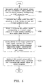
- FIG. 6 is a flow chart showing a first correction method executed by the correction system of FIG. 5 .
- FIG. 7 is a flow chart showing a second correction method of the invention.
- FIGS. 8A to 8C shows an example of function curves of a main output power function P(x) and a fine tuning output power function Pf(x) for implementing the second correction method of the invention.
- FIG. 9 is a schematic illustration showing a production line on which a radio frequency correction of the invention is performed.
- the invention uses a main output power function to represent the characteristic curves of the mobile telephones, and obtains proper DAC control values according to the main output power function so as to quickly finish the correction operation and enhance the product yield.
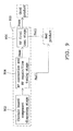
- FIG. 5 is a block diagram showing a correction system 500 for correcting a mobile telephone 506 having an automatic power control function according to a preferred embodiment of the invention.
- the mobile telephone 506 has an RF antenna and a DAC control value register.
- the correction system 500 of the invention includes a radio signal measurement apparatus 502 and a host 504.
- the correction system 500 corrects I output powers of the RF antenna of the mobile telephone 506 corresponding to I power control levels of the mobile telephone 506, wherein I is a positive integer. In the ETSI power control specification, I is equal to 32.
- I DAC (digital-to-analog conversion) control values for determining the I output powers are stored in the DAC control value register of the mobile telephone 506.
- the radio signal measurement apparatus 502 measures an output power emitted from the mobile telephone 506.
- the host 504 has an RF correction software system for correcting the mobile telephone 506 and receiving a measurement result from the radio signal measurement apparatus 502.
- FIG. 6 is a flow chart showing a first correction method executed by the correction system 500 of FIG. 5 .
- step 602 is first performed, wherein the host 504 arbitrarily selects K DAC control values D(1) to D(K) for test. Then, the radio signal measurement apparatus 502 measures K output powers PHY(1) to PHY(K) for test corresponding to the K DAC values D(1) to D(K) for test, wherein K is a positive integer smaller than I. That is, a power level converter processes the K DAC values D(1) to D(K) for test to make the RF antenna of the mobile telephone 506 output K corresponding output powers PHY(1) to PHY(K).
- the radio signal measurement apparatus 502 measures K output powers of the RF antenna to obtain K output powers PHY(1) to PHY(K) for test and records them in the host 504.
- the K DAC control values D(1) to D(k) for test may be selected from the I DAC control values that are originally stored in a DAC control value register of the mobile telephone 506.
- step 604 wherein the host 504 determines a main output power function P(x) according to the K DAC values D(1) to D(K) for test and the K output powers PHY(1) to PHY(K) for test.
- the main output power function P(x) is a polynomial function as set forth below.
- P x a r * x r + a r - 1 * x r - 1 + ... + a 1 * x + a 0
- "x" represents the DAC control value and "r” represents the positive integer.
- the coefficients a r to a 0 of the polynomial function may be obtained by substituting "x" for D(1) to D(K) and substituting P(x) for PHY(1) to PHY(K), respectively.
- the process goes to step 606, wherein the host 504 obtains I corrected DAC control values CD(1) to CD(I) corresponding to I normal output powers N(1) to N(I) according to main output power function P(x).
- the I normal output powers N(1) to N(I) satisfy the communication specification such as the ETSI power control specification.
- the I normal output powers may be 32 normal output powers corresponding to 32 power control levels shown in FIG. 2B , wherein a portion of the power control levels corresponds to the same normal output power.
- step 608 is performed.
- the output powers PW(1) to PW(I) of the radio signals are verified to determined whether or not they coincide with the I normal output powers N(1) to N(I). That is, step 608 judges whether or not PW(1) to PW(I) approximate N(1) to N(I), and whether or not the differences therebetween are smaller than the tolerances of the normal output powers. If yes, it means that the I corrected DAC control values CD(1) to CD(I) make the output power of the emitted radio signals from the mobile telephone 506 satisfy the requirement of the communication protocol.
- step 610 may be performed next, wherein the host 504 replaces the I DAC control values D(1) to D(I), which are originally stored in the DAC control value register with I corrected DAC control values CD(1) to CD(I), and then stores the I corrected DAC control values CD(1) to CD(I) in the DAC control value register of the mobile telephone 506.
- the second correction method of the invention may be adopted for fine tuning.
- the correction wants to be performed more precisely, it is also possible to use the second correction method of the invention.
- FIG. 7 is a flow chart showing a second correction method of the invention. Steps 702 to 708 are the same as steps 602 to 608, respectively, and descriptions thereof will be omitted. Step 710 is performed after step 708, wherein it judges whether or not the fine tuning has to be performed. It is assumed that the DAC control value CD(j) after the j-th correction is one of the I corrected DAC control values CD(1) to CD(I). When the step 710 judges that the j-th output power PW(j) corresponding to the DAC control value CD(j) after the j-th correction does not coincide with the j-th normal output power N(j), the fine tuning should be performed, and the process goes to step 712; or otherwise, the process goes to step 714.
- step 712 the fine tuning process is performed by the following steps.
- the host 504 determines a fine tuning output power function Pf(x) according to the DAC control value CD(j), the j-th output power PW(j), and the j-th normal output power N(j) after the j-th correction.
- the fine tuning output power function Pf(x) is a polynomial function as set forth below.
- the x value is the desired DAC control value FD(j) after the j-th fine tuning. Then the process goes to step 714.
- step 714 the host 504 replaces the DAC control value CD(j) after the j-th correction with the DAC control value FD(j) after the j-th fine tuning, and stores the DAC control value FD(j) in the DAC control value register of the mobile telephone 506.
- Other DAC control values after corrections are also simultaneously stored in the DAC control value register of the mobile telephone 506.
- step 710 even if all of the output powers PW(1) to PW(I) corresponding to the corrected DAC control values CD(1) to CD(I) coincide with the normal output powers N(1) to N(I), fine tuning may also be performed to obtain more precise DAC control values FD(1) to FD(I).
- Step 712 is executed for fine tuning if the j-th output power PW(j) corresponding to the DAC control value CD(j) after the j-th correction is requested to more precisely approximate the j-th normal output power N(j).
- the above-mentioned fine tuning method also may be utilized to obtain the DAC control value FD(j) after the j-th fine tuning.
- step 714 the host 504 replaces the DAC control value CD(j) after the j-th correction with the DAC control value FD(j) after the j-th fine tuning, and stores the DAC control value FD(j) in the DAC control value register of the mobile telephone 506.
- FIGS. 8A to 8C shows an example of function curves of a main output power function P(x) and a fine tuning output power function Pf(x) for implementing the second correction method of the invention.
- the host 504 derives 32 corrected DAC control values CD(1) to CD(32) from 32 normal output powers N(1) to N(32) according to the main output power function P'(x), as shown in FIG. 8B.
- FIG. 8B only illustrates six sets of normal output powers and corrected DAC control values.
- the host 504 obtains the fine tuning output power function Pf(x) according to the DAC control value CD(j), the j-th output power PW(j), and the j-th normal output power N(j) after the j-th correction. Then, the host 504 derives the DAC control value FD(j) after the j-th fine tuning from the fine tuning output power function Pf(x) according to j-th normal output power N(j).
- the DAC control value FD(j) after the j-th fine tuning and other corrected DAC control values are stored in the DAC control value register of the mobile telephone 506 to complete the correction.
- the corrected mobile telephone 506 can precisely emit output powers satisfying each power control level of the communication protocol.
- FIG. 9 is a schematic illustration showing a production line 900 on which a radio frequency correction of the invention is performed.
- the production and correction procedures using the correction method and system of the invention are as follows. First, main components of the mobile telephone are mounted to the circuit board in a circuit board component disposing stage 902. Next, the correction system 500 of the invention executes the first or second correction method to correct the mobile telephone 506 in an RF correction and RF repair/fine tuning stage 904. If the correction fails, the mobile telephone 506 is a defected product. If the correction succeeds, the mobile telephone 506 is transferred to the RF final test stage 906 for testing the overall mobile telephone 506.
- the invention completes the correction and fine tuning operations in the RF correction and RF repair/fine tuning stage 904.
- the invention can obtain all of the corrected DAC control values and finely tuned DAC control values by merely measuring several output powers for test, the correction may be quickly and advantageously completed.
- the actual operation results after the invention is applied to the production line indicate that the product yield is greatly enhanced since the precision of the DAC control value stored in the DAC control value register after the correction is enhanced.
Landscapes
- Mobile Radio Communication Systems (AREA)
Claims (10)
- Verfahren zum Korrigieren eines Mobiltelefons mit einer automatischen Leistungssteuerungs- (APC-) Funktion und zum Korrigieren von I Sendeleistungen einer Antenne, die zu I Leistungssteuerungspegeln des Mobiltelefons korrespondieren, wobei I eine positive Ganzzahl ist und I DAC-(digital-analog Umwandlungs-) Steuerwerte zur Ermittlung der I Sendeleistungen im Mobiltelefon gespeichert werden, wobei das Verfahren die Schritte umfasst:(a) willkürliches Auswählen von K Test-DAC-Steuerwerten und Messen von K Test-Sendeleistungen des Mobiltelefons, die zu den K Test-DAC-Steuerwerten (702) korrespondieren, wobei K eine positive Ganzzahl kleiner als I ist;(b) Ermitteln einer Haupt-Sendeleistungsfunktion gemäß den K Test-DAC-Werten und den K Test-Sendeleistungen (704);(c) Erhalten von I korrigierten DAC-Steuerwerten gemäß der Haupt-Sendeleistungsfunktion (706), die zu I Normal-Sendeleistungen korrespondieren, wobei die I Normal-Sendeleistungen eine Kommunikationsspezifikation erfüllen; und(d) Ersetzen der I DAC-Steuerwerte durch die I korrigierten DAC-Steuerwerte und Abspeichern der I korrigierten DAC-Steuerwerte im Mobiltelefon (714),dadurch gekennzeichnet, dass die Haupt-Sendeleistungsfunktion eine polynomiale Funktion ist und im Schritt (b) alle Koeffizienten der polynomialen Funktion gemäß den K Test-DAC-Steuerwerten und den K Test-Sendeleistungen ermittelt werden.
- Verfahren nach Anspruch 1, wobei die K Test-DAC-Steuerwerte aus den I DAC-Steuerwerten ausgewählt werden.
- Verfahren nach Anspruch 1, das ferner zwischen den Schritten (c) und (d) folgenden Schritt umfasst:(c1) Verifizieren, ob Sendeleistungen von Funksignalen jeweils mit den I Normal-Sendeleistungen übereinstimmen, oder nicht, wenn das Mobiltelefon jeweils die I korrigierten DAC-Steuerwerte liest, damit die Antenne die Funksignale emittiert, und Ausführen des Schritts (d), wenn die Sendeleistungen mit den I Normal-Sendeleistungen (708) übereinstimmen.
- Verfahren nach Anspruch 3, das ferner nach dem Schritt (c1) folgende Schritte aufweist:(c2) Ausführen von Schritten (c3) und (c4), wenn eine j-te Sendeleistung, die zu einem DAC-Steuerwert nach einer j-ten Korrektur korrespondiert, nicht einer j-ten Normal-Sendeleistung übereinstimmt, wobei der DAC-Steuerwert nach der j-ten Korrektur einer der I korrigierten DAC-Steuerwerte ist.(c3) Ermitteln einer Feinabstimmungs-Sendeleistungsfunktion gemäß dem DAC-Steuerwert, der j-ten Sendeleistung und der j-ten Normal-Sendeleistung nach der j-ten Korrektur; und(c4) Ableiten eines DAC-Steuerwerts nach einer j-ten Feinabstimmung aus der Feinabstimmungs-Sendeleistungsfunktion gemäß der j-ten Normal-Sendeleistung, wobei im Schritt (d) der DAC-Steuerwert nach der j-ten Korrektur durch den DAC-Steuerwert nach der j-ten Feinabstimmung ersetzt wird und der DAC-Steuerwert nach der j-ten Feinabstimmung im Mobiltelefon gespeichert wird.
- Verfahren nach Anspruch 3 das ferner nach dem Schritt (c1) folgende Schritte aufweist:(c2) Ausführen der Schritte (c3) und (c4), wenn eine zu einem DAC-Steuerwert korrespondierende j-te Sendeleistung nach einer j-ten Korrektur angefordert wird, um eine j-te Normal-Sendeleistung präziser anzunähern, wobei der DAC-Steuerwert nach der j-ten Korrektur einer der I korrigierten DAC-Steuerwerte ist;(c3) Ermitteln einer Feinabstimmungs-Sendeleistungsfunktion gemäß dem DAC-Steuerwert, der j-ten Sendeleistung und der j-ten Normal-Sendeleistung nach der j-ten Korrektur; und(c4) Ableiten eines DAC-Steuerwerts nach einer j-ten Feinabstimmung aus der Feinabstimmungs-Sendeleistungsfunktion gemäß der j-ten Normal-Sendeleistung,wobei im Schritt (d) der DAC-Steuerwert nach der j-ten Korrektur durch den DAC-Steuerwert nach der j-ten Feinabstimmung ersetzt wird und der DAC-Steuerwert nach der j-ten Feinabstimmung im Mobiltelefon gespeichert wird.
- Korrektursystem zum Korrigieren eines Mobiltelefons (506) mit einer automatischen Leistungssteuerungs- (APC-) Funktion und zum Korrigieren von I Sendeleistungen einer Antenne (312), die zu I Leistungssteuerungspegeln des Mobiltelefons korrespondieren, wobei I eine positive Ganzzahl ist und I DAC- (digital-analog Umwandlungs-) Steuerwerte zur Ermittlung der I Sendeleistungen im Mobiltelefon gespeichert werden, wobei das Korrektursystem umfasst:eine Funksignal-Messvorrichtung (502) zum Messen von Sendeleistungen, die vom Mobiltelefon emittiert werden; undeinen Host (504) zum Korrigieren des Mobiltelefons, wobei der Host mit der Funksignal-Messvorrichtung elektrisch verbunden ist, wobei der Host und die Funksignal-Messvorrichtung die nachfolgenden Schritte ausführen, um das Mobiltelefon zu korrigieren;dadurch gekennzeichnet, dass die Haupt-Sendeleistungsfunktion eine polynomiale Funktion ist und der Host im Schritt (b) alle Koeffizienten der polynomialen Funktion gemäß den K Test-DAC-Steuerwerten und den K Test-Sendeleistungen für einen Test ermittelt.(a) Bewirken, dass der Host willkürlich K Test-DAC-Steuerwerte auswählt und dass die Funksignal-Messvorrichtung danach K Test-Sendeleistungen des Mobiltelefons misst, die zu den K Test-DAC-Steuerwerten korrespondieren, wobei K eine positive Ganzzahl kleiner als I ist;(b) Bewirken, dass der Host eine Haupt-Sendeleistungsfunktion gemäß den K Test-DAC-Werten und den K Test-Sendeleistungen ermittelt;(c) Bewirken, dass der Host I korrigierte DAC-Steuerwerte gemäß der Haupt-Sendeleistungsfunktion erhält, die zu I Normal-Sendeleistungen korrespondieren, wobei die I Normal-Sendeleistungen eine Kommunikationsspezifikation erfüllen; und(d) Bewirken, dass der Host die I DAC-Steuerwerte durch die I korrigierten DAC-Steuerwerte ersetzt und die I korrigierten DAC-Steuerwerte im Mobiltelefon speichert,
- Korrektursystem nach Anspruch 6, wobei die K Test-DAC-Steuerwerte aus den I DAC-Steuerwerten ausgewählt werden.
- Korrektursystem nach Anspruch 6, wobei der Host und die Funksignal-Messvorrichtung ferner den nachfolgenden Schritt zwischen den Schritten (c) und (d) ausführen, um das Mobiltelefon zu korrigieren:(c1) Verifizieren, ob Sendeleistungen von Funksignalen, die von der Funksignal-Messvorrichtung gemessen wurden, jeweils mit den I Normal-Sendeleistungen übereinstimmen, oder nicht, wenn das Mobiltelefon jeweils die I korrigierten DAC-Steuerwerte liest, damit die Antenne die Funksignale emittiert.
- Korrektursystem nach Anspruch 8, wobei der Host und die Funksignal-Messvorrichtung ferner die nachfolgenden Schritte nach dem Schritt (c1) ausführen, um das Mobiltelefon zu korrigieren:(c2) Ausführen von Schritten (c3) und (c4), wenn eine j-te Sendeleistung, die zu einem DAC-Steuerwert korrespondiert, nach einer j-ten Korrektur nicht mit einer j-ten Normal-Sendeleistung übereinstimmt, wobei der DAC-Steuerwert nach der j-ten Korrektur einer der I korrigierten DAC-Steuerwerte ist; und(c3) Bewirken, dass der Host eine Feinabstimmungs-Sendeleistungsfunktion gemäß dem DAC-Steuerwert, der j-ten Sendeleistung und der j-ten Normal-Sendeleistung nach der j-ten Korrektur ermittelt; und(c4) Bewirken, dass der Host einen DAC-Steuerwert nach einer j-ten Feinabstimmung aus der Feinabstimmungs-Sendeleistungsfunktion gemäß der j-ten Normal-Sendeleistung ableitet, wobei der Host im Schritt (d) den DAC-Steuerwert nach der j-ten Korrektur durch den DAC-Steuerwert nach der j-ten Feinabstimmung ersetzt und den DAC-Steuerwert nach der j-ten Feinabstimmung im Mobiltelefon speichert.
- Korrektursystem nach Anspruch 8, wobei der Host und die Funksignal-Messvorrichtung ferner die nachfolgenden Schritte nach dem Schritt (c1) ausführen, um das Mobiltelefon zu korrigieren:(c2) Ausführen von Schritten (c3) und (c4), wenn eine j-te Sendeleistung, die zu einem DAC-Steuerwert nach einer j-ten Korrektur korrespondiert, angefordert wird, um eine j-te Normal-Sendeleistung präziser anzunähern, wobei der DAC-Steuerwert nach der j-ten Korrektur einer der I korrigierten DAC-Steuerwerte ist;(c3) Bewirken, dass der Host eine Feinabstimmungs-Sendeleistungsfunktion gemäß dem DAC-Steuerwert, der j-ten Sendeleistung und der j-ten Normal-Sendeleistung nach der j-ten Korrektur ermittelt; und(c4) Bewirken, dass der Host einen DAC-Steuerwert nach einer j-ten Feinabstimmung aus der Feinabstimmungs-Sendeleistungsfunktion gemäß der j-ten Normal-Sendeleistung ableitet,wobei der Host in einem Schritt (d) den DAC-Steuerwert nach der j-ten Korrektur durch den DAC-Steuerwert nach der j-ten Feinabstimmung ersetzt und den DAC-Steuerwert nach der j-ten Feinabstimmung im Mobiltelefon speichert.
Priority Applications (1)
| Application Number | Priority Date | Filing Date | Title |
|---|---|---|---|
| EP20040009223 EP1589666B1 (de) | 2004-04-19 | 2004-04-19 | Verfahren zur Korrektur der automatischen Leistungsregelungsfunktion eines Mobiltelefons und System dafür |
Applications Claiming Priority (1)
| Application Number | Priority Date | Filing Date | Title |
|---|---|---|---|
| EP20040009223 EP1589666B1 (de) | 2004-04-19 | 2004-04-19 | Verfahren zur Korrektur der automatischen Leistungsregelungsfunktion eines Mobiltelefons und System dafür |
Publications (2)
| Publication Number | Publication Date |
|---|---|
| EP1589666A1 EP1589666A1 (de) | 2005-10-26 |
| EP1589666B1 true EP1589666B1 (de) | 2012-03-28 |
Family
ID=34924655
Family Applications (1)
| Application Number | Title | Priority Date | Filing Date |
|---|---|---|---|
| EP20040009223 Expired - Lifetime EP1589666B1 (de) | 2004-04-19 | 2004-04-19 | Verfahren zur Korrektur der automatischen Leistungsregelungsfunktion eines Mobiltelefons und System dafür |
Country Status (1)
| Country | Link |
|---|---|
| EP (1) | EP1589666B1 (de) |
Families Citing this family (1)
| Publication number | Priority date | Publication date | Assignee | Title |
|---|---|---|---|---|
| CN112235762A (zh) * | 2020-10-14 | 2021-01-15 | 重庆邮电大学 | 一种信令下的eMTC终端功率控制的快速校准方法 |
Family Cites Families (3)
| Publication number | Priority date | Publication date | Assignee | Title |
|---|---|---|---|---|
| US6507732B1 (en) * | 1999-09-14 | 2003-01-14 | Lucent Technologies Inc. | Dynamic path gain compensation for radios in wireless communication systems |
| US7092686B2 (en) * | 2001-03-08 | 2006-08-15 | Siemens Communications, Inc. | Automatic transmit power control loop |
| GB2393595B (en) | 2002-09-26 | 2007-04-04 | Qualcomm | A transmitter and a method of calibrating power in signals output from a transmitter |
-
2004
- 2004-04-19 EP EP20040009223 patent/EP1589666B1/de not_active Expired - Lifetime
Also Published As
| Publication number | Publication date |
|---|---|
| EP1589666A1 (de) | 2005-10-26 |
Similar Documents
| Publication | Publication Date | Title |
|---|---|---|
| CN102740438B (zh) | 利用内部功率测量对发射机的校准 | |
| US8509702B2 (en) | Methods of calibrating a device under test to communicate wirelessly | |
| CN110896330B (zh) | 一种适用于多频点多功率点的发射功率校准方法及装置 | |
| CN106899359A (zh) | 一种wifi模块射频校准方法 | |
| US7826577B2 (en) | Method for frequency acquisition of a mobile communications device | |
| CN106324479A (zh) | 一种芯片校准方法、电路及芯片 | |
| US20090163155A1 (en) | Methods for calibrating a transmitter, and radio transmitter | |
| US7516428B2 (en) | Microwave circuit performance optimization by on-chip digital distribution of operating set-point | |
| EP1589666B1 (de) | Verfahren zur Korrektur der automatischen Leistungsregelungsfunktion eines Mobiltelefons und System dafür | |
| CN109470939B (zh) | 一种线损点检系统及方法 | |
| CN101383666B (zh) | 一种适用于多种信号带宽的功率校准方法 | |
| US7106790B2 (en) | Method and apparatus for measuring a signal spectrum | |
| US6477389B1 (en) | Method for compensating for transmission power deviations of channels in a mobile phone | |
| US20080153436A1 (en) | Assessing the performance of radio devices | |
| KR100603652B1 (ko) | 자동 전력 제어 기능을 갖는 모바일 폰의 정정 방법 및 그정정 시스템 | |
| CN101036325B (zh) | 用于移动电话装置发送和/或接收校准的方法和系统 | |
| US6642780B2 (en) | Variable frequency filter circuit | |
| CN100417239C (zh) | 根据移动通信终端的频率来补偿接收功率的方法 | |
| CN101136670A (zh) | 基站功率控制方法和装置 | |
| CN1266968C (zh) | 校正具有自动能量控制功能的移动电话的方法及其校正系统 | |
| CN103929770A (zh) | 校正待测装置以无线进行通信的方法 | |
| US7542724B2 (en) | Method and device of correcting received levels in mobile communication terminal | |
| JP2004509549A (ja) | 移動通信装置の移動体部分における高周波発振器周波数を較正する方法 | |
| EP4338495B1 (de) | Automatische hf-sendeleistungssteuerung für over-the-air-prüfung | |
| US20060217092A1 (en) | Method for calibration of a signal receiver |
Legal Events
| Date | Code | Title | Description |
|---|---|---|---|
| PUAI | Public reference made under article 153(3) epc to a published international application that has entered the european phase |
Free format text: ORIGINAL CODE: 0009012 |
|
| AK | Designated contracting states |
Kind code of ref document: A1 Designated state(s): AT BE BG CH CY CZ DE DK EE ES FI FR GB GR HU IE IT LI LU MC NL PL PT RO SE SI SK TR |
|
| AX | Request for extension of the european patent |
Extension state: AL HR LT LV MK |
|
| 17P | Request for examination filed |
Effective date: 20060306 |
|
| AKX | Designation fees paid |
Designated state(s): DE FR GB |
|
| 17Q | First examination report despatched |
Effective date: 20090429 |
|
| RAP1 | Party data changed (applicant data changed or rights of an application transferred) |
Owner name: HTC CORPORATION |
|
| GRAP | Despatch of communication of intention to grant a patent |
Free format text: ORIGINAL CODE: EPIDOSNIGR1 |
|
| GRAS | Grant fee paid |
Free format text: ORIGINAL CODE: EPIDOSNIGR3 |
|
| GRAA | (expected) grant |
Free format text: ORIGINAL CODE: 0009210 |
|
| AK | Designated contracting states |
Kind code of ref document: B1 Designated state(s): DE FR GB |
|
| REG | Reference to a national code |
Ref country code: GB Ref legal event code: FG4D |
|
| REG | Reference to a national code |
Ref country code: DE Ref legal event code: R096 Ref document number: 602004037074 Country of ref document: DE Effective date: 20120524 |
|
| PLBE | No opposition filed within time limit |
Free format text: ORIGINAL CODE: 0009261 |
|
| STAA | Information on the status of an ep patent application or granted ep patent |
Free format text: STATUS: NO OPPOSITION FILED WITHIN TIME LIMIT |
|
| 26N | No opposition filed |
Effective date: 20130103 |
|
| REG | Reference to a national code |
Ref country code: DE Ref legal event code: R097 Ref document number: 602004037074 Country of ref document: DE Effective date: 20130103 |
|
| REG | Reference to a national code |
Ref country code: FR Ref legal event code: PLFP Year of fee payment: 13 |
|
| REG | Reference to a national code |
Ref country code: FR Ref legal event code: PLFP Year of fee payment: 14 |
|
| REG | Reference to a national code |
Ref country code: FR Ref legal event code: PLFP Year of fee payment: 15 |
|
| PGFP | Annual fee paid to national office [announced via postgrant information from national office to epo] |
Ref country code: FR Payment date: 20230309 Year of fee payment: 20 |
|
| PGFP | Annual fee paid to national office [announced via postgrant information from national office to epo] |
Ref country code: GB Payment date: 20230302 Year of fee payment: 20 |
|
| PGFP | Annual fee paid to national office [announced via postgrant information from national office to epo] |
Ref country code: DE Payment date: 20230307 Year of fee payment: 20 |
|
| REG | Reference to a national code |
Ref country code: DE Ref legal event code: R071 Ref document number: 602004037074 Country of ref document: DE |
|
| REG | Reference to a national code |
Ref country code: GB Ref legal event code: PE20 Expiry date: 20240418 |
|
| PG25 | Lapsed in a contracting state [announced via postgrant information from national office to epo] |
Ref country code: GB Free format text: LAPSE BECAUSE OF EXPIRATION OF PROTECTION Effective date: 20240418 |
|
| PG25 | Lapsed in a contracting state [announced via postgrant information from national office to epo] |
Ref country code: GB Free format text: LAPSE BECAUSE OF EXPIRATION OF PROTECTION Effective date: 20240418 |