FIELD OF THE INVENTION
The present invention relates to an electric motor
unit with a controller and more particularly to an
electric motor unit with a controller of a machinery
and electricity integration type used in components of
the drive system of a car such as a transmission and
four-wheel drive transfer.
BACKGROUND OF THE INVENTION
As an electric motor unit with a controller for
switching the operation condition of the drive line of
a car such as a transmission and four-wheel drive
transfer, there is a machinery and electricity
integration type (for example, USP 6,155,126) available
which has a built-in gear train of deceleration system
for driving to rotate a switching operation member such
as a shift rail of four-wheel drive transfer in one
housing assembly, has an attached electric motor for
driving to rotate the gear train in the housing
assembly, and furthermore has an attached printed
wiring board in which a microcontroller for controlling
to drive the electric motor and a non-contact sensor
for sensing the magnetic pole of a magnet ring attached
to a drive pinion of the electric motor are mounted.
In the conventional electric motor unit with a
controller as mentioned above, the printed wiring board
for control mounting the microcontroller is
incorporated in the housing assembly having the built-in
gear train, so that the printed wiring board is
exposed in a very bad atmosphere in which oil of the
housing assembly and worn metallic powder of the gears
are floating, and the magnetic field for the non-contact
sensor is disturbed, and there is a fear of a
malfunction.
Further, the housing assembly becomes warm due to
heat of the motor and frictional heat by rotation of
the gear train, so that the printed wiring board in the
housing assembly is exposed in a high-temperature
atmosphere and there is a fear of a thermal malfunction.
Further, in the conventional electric motor unit
with a controller as mentioned above, for suppressing
changing in the relative location (separation distance
= air gap) between the magnet ring on the gear side and
the non-contact sensor on the housing assembly side and
stably detecting an accurate rotational position, it is
not taken into account to minimize variations due to
assembling of the printed wiring board and changing due
to thermal expansion of the housing assembly.
Therefore, it is difficult to detect stably an accurate
rotational position.
The wiring board for controlling to drive the
electric motor includes a large current wiring pattern
of the motor drive system, a signal pattern, and a
sensor pattern and the prior art arranges a large
current wiring pattern at the same potential extending
over a plurality of conductor layers, so that
positional interference with another signal pattern in
the board occurs, and the pattern width is made thinner,
and the pattern length is made longer, thus a problem
arises that generation of heat due to the large current
is great, and the heat radiation is bad, and a
malfunction due to the thermal effect is caused easily.
In the prior art, the large current wiring pattern
and sensor signal pattern branch at a plurality of
points, so that, a potential difference due to the
large current is generated in the sensor signal pattern
and a problem arises that the sensor accuracy is
degraded. Further, in the prior art, the case of the
wiring board and the housing assembly are not connected
electrically, so that a problem arises that the static
electricity resistance is inferior.
In the prior art, for RAM reading, RAM rewriting,
ROM reading, and ROM rewriting in the microcontroller
(microcomputer) mounted in the wiring board, exclusive
signal lines are necessary and a problem of an increase
in cost and an increase in the number of steps of the
harness and terminal arises.
SUMMARY OF THE INVENTION
The present invention was developed to solve the
aforementioned problems and is intended to provide an
electric motor unit with a controller of a machinery
and electricity integration type which eliminates the
possibilities of variations and malfunctions due to
mechanical and thermal factors, indicates excellent
operation reliability and durability, and is simple and
highly efficient.
To accomplish the above object, the electric motor
unit with a controller of the present invention
includes a gear case having built-in gears, an electric
motor attached to the gear case for driving to rotate
the gears, and a controller case attached to the gear
case having a built-in electric controller for
controlling to drive the electric motor, and a sensing
element such as a magnet is attached to the gears, and
a sensor for sensing the sensing element and detecting
the rotational angle of the gears is attached in the
controller case, and the gear case has a cylindrical
opening concentric with the rotational center of the
gears, and the controller case has a cylindrical part
fit into the cylindrical opening, and by the fitting
between the cylindrical part and the cylindrical
opening, the controller case is positioned and mounted
on the gear case.
According to the electric motor unit with a
controller of the present invention, in the cylindrical
opening concentric with the rotational center of the
gears formed in the gear case, the cylindrical part of
the controller case is fit, and by the fitting between
the cylindrical part and the cylindrical opening, the
controller case is positioned and mounted on the gear
case, so that the attaching position of the controller
case to the gear case eliminates variations in the
assembling, thereby is uniquely decided mechanically
and highly accurately, therefore the relative position
relationship between the sensor on the controller case
side and the sensing element on the gear case side is
decided highly accurately, and the accurate rotational
position can be detected stably.
Furthermore, in the fitting part between the
cylindrical part and the cylindrical opening, an O-ring
made of an elastic body is clamped and by the center
adjusting operation of the O-ring, the attaching
position accuracy of the controller case to the gear
case can be enhanced.
Particularly, the non-contact rotary sensor of a
magnetism detection type detects the rotational angle
of the rotator (gear) by changing in the magnetic field,
so that to enhance the detection accuracy, the magnetic
field acting on the sensor element is preferably
symmetrical to the sensor element with respect to point.
Therefore, the sensor on the controller case side must
be arranged on the same axis as that of the magnet
which is the sensing element on the rotator. In this
case, the controller case is positioned and mounted on
the gear case by the fitting between the cylindrical
part and the cylindrical opening, and the attaching
position accuracy of the controller case to the gear
case is enhanced by the center adjusting operation of
the O-ring, so that the sensor can be arranged on the
same axis as that of the rotational center of the
sensing element on the gears, thus the sensor accuracy
can be improved.
Further, in the electric motor unit with a
controller of the present invention, the controller
case is a closed structure case hermetically separated
from the inside of the gear case.
In the electric motor unit with a controller of the
present invention, the electric controller stored in
the controller case will not be exposed in a very bad
atmosphere including oil in the gear case and worn
metallic powder of the gears.
Further, the electric motor unit with a controller
of the present invention includes a gear case having
built-in gears, an electric motor attached to the gear
case for driving to rotate the gears, and a controller
case attached to the gear case having a built-in
electric controller for controlling to drive the
electric motor, and a sensing element such as a magnet
is attached to the gears, and a sensor for sensing the
sensing element and detecting the rotational angle of
the gears is attached in the controller case, and
members for deciding the separation distance between
the sensing element and the sensor are composed of the
same kind of materials relating to the coefficient of
linear expansion.
According to the electric motor unit with a
controller of the present invention, the members for
deciding the separation distance between the sensing
element and the sensor are composed of the materials
which have the same kind of the linear expansion
coefficient substantially such as an aluminum series
metal, so that even if these members are thermally
expanded or thermally shrunk, the separation distance
between the sensing element and the sensor is varied
little or not varied and the accurate rotational
position can be detected stably.
Further, in the electric motor unit with a
controller of the present invention, a sensing element
is mounted on the gears by a mount member and the
members for deciding the separation distance between
the sensing element and the sensor include the mount
member, gear case, and controller case.
According to the electric motor unit with a
controller of the present invention, the mount member
of the sensing element, gear case, and controller case
are composed of the materials which have the same kind
of the linear expansion coefficient substantially such
as an aluminum series metal, so that even if these
members are thermally expanded or thermally shrunk, the
separation distance between the sensing element and the
sensor is varied little or not varied and the accurate
rotational position can be detected stably.
Further, the electric motor unit with a controller
of the present invention includes a gear case having
built-in gears, an electric motor attached to the gear
case for driving to rotate the gears, and a controller
case attached to the gear case having a built-in wiring
board of an electric controller for controlling to
drive the electric motor, and the wiring board is
composed of a multi-layer wiring board with many
insulating base materials having conductor layers
laminated in layers, and in the conductor layer of each
insulating base material, the large current wiring
pattern is dispersed and arranged.
According to the electric motor unit with a
controller of the present invention, the large current
wiring pattern is dispersed and arranged in the
conductor layers of the insulating base materials, so
that it is possible to widen the current wiring pattern
and arrange (layout) the pattern with the shortest wire
length. The pattern resistance depends on the
conductor pattern width and conductor pattern length,
so that when the conductor pattern is wide and the
conductor pattern is short, the pattern resistance can
be suppressed, and the resistance generation of heat
due to the current flowing though the large current
wiring pattern can be reduced, and it is thermally
advantageous.
Further, the electric motor unit with a controller
of the present invention includes a gear case having
built-in gears, an electric motor attached to the gear
case for driving to rotate the gears, and a controller
case attached to the gear case having a built-in wiring
board of an electric controller for controlling to
drive the electric motor, and the wiring board includes
the large current wiring pattern, signal pattern, and
sensor pattern, and the large current wiring pattern,
signal pattern, and sensor pattern are connected at one
point.
According to the electric motor unit with a
controller of the present invention, the large current
wiring pattern, signal pattern, and sensor pattern are
connected at one point, so that even if a large current
flows through the large current wiring pattern, an
occurrence of a potential difference between the ground
of the signal pattern and the ground of the sensor
pattern is avoided and the adverse affect by the large
current on another signal system and sensor system can
be suppressed.
Further, the electric motor unit with a controller
of the present invention includes a gear case having
built-in gears, an electric motor attached to the gear
case for driving to rotate the gears, and a controller
case attached to the gear case having a built-in wiring
board of an electric controller for controlling to
drive the electric motor, and the wiring board is
adhered and fixed to the controller case by two kinds
of adhesives such as a high temperature conductive
adhesive and a very strong adhesive whose adhesive
strength is higher than that of the high temperature
conductive adhesive. As a high temperature conductive
adhesive, there is a resin series adhesive including a
metallic filler having high thermal conductivity
available and as a very strong adhesive, there is an
ordinary silicon series adhesive available.
According to the electric motor unit with a
controller of the present invention, the wiring board
is adhered and fixed to the controller case by two
kinds of adhesives such as the high temperature
conductive adhesive and the very strong adhesive whose
adhesive strength is higher than that of the high
temperature conductive adhesive, so that that the heat
of the wiring board is effectively conducted to the
controller case by the high temperature conductive
adhesive and that the wiring board is adhered to the
controller case at a required adhesive strength by the
very strong adhesive are compatible.
Further, the electric motor unit with a controller
of the present invention includes a gear case having
built-in gears, an electric motor attached to the gear
case for driving to rotate the gears, and a controller
case attached to the gear case having a built-in wiring
board of an electric controller for controlling to
drive the electric motor, and the controller case and
gear case are composed of a conductive material and the
grounding part of the wiring board, controller case,
and gear case are electrically connected.
According to the electric motor unit with a
controller of the present invention, the grounding part
of the wiring board, controller case, and gear case are
electrically connected, so that the electric capacity
of the grounding part of the wiring board is increased,
and a disturbance such as high frequency noise
transferred from an external connector can be absorbed,
and a control circuit having a superior noise
resistance can be realized.
Further, the electric motor unit with a controller
of the present invention includes a gear case having
built-in gears, an electric motor attached to the gear
case for driving to rotate the gears, and a controller
case attached to the gear case having a built-in
microcomputer for controlling to drive the electric
motor, and has a function for performing RAM reading,
RAM rewriting, ROM reading, and ROM rewriting in the
microcomputer by controller area network (CAN)
communication.
According to the electric motor unit with a
controller of the present invention, RAM reading, RAM
rewriting, ROM reading, and ROM rewriting in the
microcomputer can be performed by CAN communication and
the debug line (interface cable) of the microcomputer
and connector pins can be reduced. By doing this, the
number of connector pins can be reduced and the
communication wiring cost can be decreased.
Further, the electric motor unit with a controller
of the present invention switches the operation
condition of the drive line of a car such as a
transmission and four-wheel drive transfer.
Further, according to the electric motor unit with
a controller of the present invention, in an electric
motor unit with a controller for switching the
operation condition of the drive line of a car such as
a transmission and four-wheel drive transfer, the
operation and effect of the electric motor unit with a
controller of the aforementioned invention can be
obtained.
BRIEF DESCRIPTION OF THE DRAWINGS
Fig. 1 is a block diagram showing the power
transfer system of a car of a four-wheel drive type to
which the electric motor unit with a controller of the
present invention is applied.
Fig. 2 is an exploded perspective view of the upper
half showing an embodiment of the electric motor unit
with a controller of the present invention.
Fig. 3 is an exploded perspective view of the lower
half showing an embodiment of the electric motor unit
with a controller of the present invention.
Fig. 4 is a cross sectional view showing an
embodiment of the electric motor unit with a controller
of the present invention.
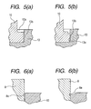
Figs. 5(a) and 5(b) are enlarged cross sectional
views showing the joining structure of the warm wheel
and magnet holder of the electric motor unit with a
controller of an embodiment.
Figs. 6(a) and 6(b) are enlarged cross sectional
views showing the joining structure of the magnet
holder and magnet member of the electric motor unit
with a controller of an embodiment.
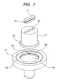
Fig. 7 is an exploded perspective views of the
joining part of the warm wheel, magnet holder, and
magnet member of the electric motor unit with a
controller of an embodiment.
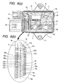
Fig. 8(a) is a plan view of the board layout part
of the electric motor unit with a controller of an
embodiment and Fig. 8(b) is a plan view showing the
enlarged wiring part of the wiring board.
Fig. 9 is a functional block diagram of the shift
controller of the electric motor unit with a controller
of an embodiment.
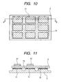
Fig. 10 is an illustration showing the board
adhesion structure of the electric motor unit with a
controller of an embodiment.
Fig. 11 is a cross sectional view along the line A-A
shown in Fig. 10.
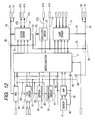
Fig. 12 is an electric circuit diagram of the
wiring pattern formed on the wiring board of the
electric motor unit with a controller of an embodiment.
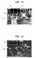
Fig. 13 is a plan view of the first layer of the
wiring board of the multilayer structure of the
electric motor unit with a controller of an embodiment.
Fig. 14 is a plan view of the second layer of the
wiring board of the multilayer structure of the
electric motor unit with a controller of an embodiment.
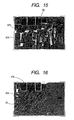
Fig. 15 is a plan view of the third layer of the
wiring board of the multilayer structure of the
electric motor unit with a controller of an embodiment.
Fig. 16 is a plan view of the fourth layer of the
wiring board of the multilayer structure of the
electric motor unit with a controller of an embodiment.
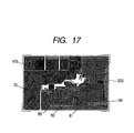
Fig. 17 is a plan view of the fifth layer of the
wiring board of the multilayer structure of the
electric motor unit with a controller of an embodiment.
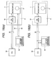
Figs. 18(a) and 18(b) are illustrations showing
communication of the electric motor unit with a
controller of an embodiment.
DESCRIPTION OF THE PREFERRED EMBODIMENTS
Hereinafter, the embodiments of the present
invention will be explained in detail with reference to
the accompanying drawings.
Power transfer system of a four-wheel drive car:
Fig. 1 shows the power transfer system of a car of
a four-wheel drive type to which the electric motor
unit with a controller of the present invention is
applied.
The drive train of the four-wheel drive car is
schematically shown with a reference number of 100.
The drive train 100 of the four-wheel drive car is
connected to a motor 101 such an internal combustion
engine and has a transmission 102 driven by the motor
101. The transmission 102 may be either of the general
automatic type and manual type.
To the latter stage of the transmission 102, a
transfer case assembly 103 for four-wheel drive
switching is connected. The transfer case assembly 103
always supplies driving force to a rear wheel drive
line 108 including a back thrust shaft 104, a back
differential device 105, a pair of left and right back
wheel shafts 106, and a pair of left and right back
tire and wheel assemblies 107.
Further, the transfer case assembly 103 selectively
supplies driving force to a front wheel drive line 113
including a front thrust shaft 109, a front
differential device 110, a pair of left and right front
wheel shafts 111, and a pair of left and right front
tire and wheel assemblies 112.
The pair of left and right front tire and wheel
assemblies 112 are preferably connected directly to the
pair of left and right front wheel shafts 111
respectively. In place of it, a pair of stopper hubs
114 which can be operated manually or remote controlled
may be arranged operably between the pair of left and
right front wheel shafts 111 and the pair of left and
right front tire and wheel assemblies 112 respectively
and be selectively connected. Both of the rear wheel
drive line 108 which is a main drive line and the front
wheel drive line 113 which is a secondary drive line
can arrange universal couplings 115 at the shaft
couplings of the back thrust shaft 104 and the front
thrust shaft 109. The universal couplings 115 permit
static and dynamic shifts and inconsistency between the
thrust shafts and the elements.
Mode changeover switch:
Within a range which a car driver can reach, a
driver control board or an assembly 120 is arranged.
The assembly 120 has a manual mode changeover switch
121 for selecting one of a plurality of running modes
switched and set by the transfer case assembly 103.
Overall structure of the electric motor unit with a
controller:
A machinery and electricity integration type
controller for switching the transfer case assembly 103
is called an electric motor unit with a controller
(shift controller) 200. The electric motor unit with a
controller 200 is installed beside the transfer case
assembly 103.
The electric motor unit with a controller 200 has
an output shaft 11 having a hand-reeling hole and by
the output shaft 11 (refer to Figs. 2 and 4), is
connected to the shift rail 116 of the transfer case
assembly 103 in relation to torque transfer. The
electric motor unit with a controller 200 inputs an
output signal of the mode changeover switch 121 and car
speed information, engine speed information, and
throttle position information from an engine control
unit (not drawn), and makes the output shaft 11 follow
the target rotational angle according these input
information.
The electric motor unit with a controller 200 will
be explained in detail by referring to Figs. 2 to 4.
The electric motor unit with a controller 200
includes a gear case 6 made of aluminum as a main
structural body. The gear case 6 supports rotatably a
worm wheel 13 in the case, that is, a gear chamber 25
by a bush 22 of a bearing section 6a. The output shaft
11 is restricted on movement in the direction of the
shaft line to the gear case 6 via a washer 23 by a
fixing ring 24 joined to the front end of the output
shaft 11.
On the side of the gear case 6, an electric motor
16 for generating driving force is attached by set
screws 69. The electric motor 16 has a worm gear 17 on
the output section. As a material of the worm gear 17,
an iron series metal, aluminum, and resin may be
considered, though in this embodiment, an iron material
having a highest strength is adopted. The worm gear 17
is stored in the gear case 6 and meshes with the worm
wheel 13.
On the top of the worm wheel 13, a columnar magnet
holder 10 made of aluminum which is a mount member of
the sensing element is fixed concentrically with the
rotational center of the worm wheel 13 by metal flow,
fitting junction, or an adhesive. On the top of the
magnet holder 10, a cylindrical magnet member 8 which
is a sensing element is fixed by caulking, fitting
junction, or an adhesive. Here, the magnet member 8,
the magnet holder 10, the worm wheel 13, and the output
shaft 11 all rotate integrally.
A preferred and detailed embodiment of junction
between the worm wheel 13 and the magnet holder 10 and
junction between the magnet holder 10 and the magnet
member 8 will be explained by referring to Fig. 5 to 7.
On the top of the worm wheel 13, at the position
concentric with the rotational center of the worm wheel
13, a circular magnet holder insertion concavity 13a is
formed. On the inner peripheral surface of the magnet
holder insertion concavity 13a, a circular ring-shaped
concave slit 13b and a key slit-shaped perpendicular
concave slit 13c are formed. On the top of the worm
wheel 13, on the outer periphery side of the magnet
holder insertion concavity 13a, the circular ring-shaped
concave slit 13b is formed concentrically with
the magnet holder insertion concavity 13a.
For the junction between the magnet holder 10 and
the worm wheel 13, metal flow is used. Concretely, the
magnet holder is inserted into the magnet holder
insertion concavity 13a of the worm wheel 13 and then
at a load of plastic-deforming an insertion flange 10a
of the magnet holder 10, the insertion flange 10a of
the magnet holder 10 is punched from the top toward the
bottom.
By doing this, as shown in Fig. 5(b), the magnet
holder material (aluminum) flows in the circular ring-shaped
concave slit 13b of the worm wheel 13 and the
vertical movement of the magnet holder 10 is restricted.
Further, the magnet holder material flows also in the
perpendicular concave slit 13c of the worm wheel 13, so
that a key junction state is obtained and the magnet
holder 10 is prevented from rotational displacement
from the worm wheel 13. Further, the circular ring-shaped
concave slit 13b acts as a buffer slit for
preventing the external form of the worm wheel 13 from
deformation by the force in the direction of the outer
periphery of the worm wheel of the magnet holder 10
flowing in by the punching.
Further, one or more circular ring-shaped concave
slits 13b and perpendicular concave slits 13c of the
worm wheel 13 are required and the shape of these slits
may be the mess shape formed by knurling. The slit
depth is set to the difference or more between the heat
shrinkage amount of the joined part (flow-in part) of
the magnet holder 10 and the heat shrinkage amount of
the worm wheel 13. By doing this, at the time of heat
shrinkage, the margin to be caught by the circular
ring-shaped concave slits 13b and perpendicular concave
slits 13c will not eliminated, thus the magnet holder
13 can be prevented from moving in the vertical
direction and rotational direction (dropping out of the
magnet holder).
The magnet member 8 is a bar magnet having S and N
magnetic poles at both ends and on the side periphery,
a concave slit 8a is formed. On the top of the magnet
holder 10, a rectangular magnet member insertion
concavity 10b for inserting the magnet member 8 is
formed so as to extend in the radial direction passing
the center of the magnet holder 10.
For the junction between the magnet member 8 and
the magnet holder 10, caulking is used. Concretely,
the magnet member 8 is inserted into the magnet member
insertion concavity 13b of the magnet holder 10 and
then the outer peripheral part of the magnet member
insertion concavity 13b of the magnet holder 10, at a
pressure of plastic-deforming the magnet holder member,
is punched from the top toward the bottom.
By doing this, as shown in Fig. 6(b), the magnet
holder material flows in the concave slit 8a of the
magnet member 8 and is caulked. By this caulking, the
magnet member 8 is fixed to the magnet holder 10. Here,
the depth of the concavity slit 8a is set to the
difference or more between the heat shrinkage amount of
the magnet holder 10 and the heat shrinkage amount of
the magnet member 8. By doing this, at the time of
heat shrinkage, the margin to be caught by the concave
slit 8a will not be eliminated, thus the magnet member
8 can be prevented from moving in the vertical
direction (dropping out of the magnet member).
On the upper part of the gear case 6, by set screws
9 and bushes 12, a board case 7 of a plastic molded
article and a board base member 5 made of aluminum are
together tightened and fixed. On the upper part of the
board case 7, a board cover 1 is fixed hermetically by
an epoxy or silicone adhesive. The assembly of the
board case 7, the board base member 5, and the board
cover 1 forms a controller case 56 of a closed
structure.
The controller case 56 fixes internally a board
chamber 26 separated hermetically from the inside (the
gear chamber 25) of the gear case 6 by the board base
member 5. The board base member 5 is a bottom plate of
the controller case 56 and serves as a partition for
hermetically separating the gear chamber 25 and the
board chamber 26.
On the board case 7, an electric motor connector 19
and an external connector 20 are formed integrally. To
the electric motor connector 19, an electric motor
connector 18 of motor connection lines 14 and 15 of the
electric motor 16 is electrically connected. The
external connector 20 is used to communicate with the
outside of the shift controller, supply a supply
voltage, and input an electric signal.
On the board base member 5 in the board chamber 26,
a wiring board 2 for an electric controller (shift
controller) is positioned by positioning pins 93 and
then is adhered and fixed by an epoxy or silicone
adhesive. On the wiring board 2, a non-contact rotary
sensor 3 of a magnetism detection method, a
microcomputer 4, and an electric motor drive circuit 47
are mounted.
The wiring board 2 is stored in the clean board
chamber 26 of the controller case 56 hermetically
separated from the inside of the gear case 6, that is,
the gear chamber 25, so that the wiring board 2 is not
exposed in a very bad atmosphere including oil of the
gear chamber 25 and worn metallic powder of the gears,
and the wiring board 2 can be protected from substances
adversely affecting the electronic circuit such as dust
and oil which are considered to be generated in the
machines, and malfunctions of the electric controller
due to short-circuiting of the conductors of the wiring
board 2 will not be caused.
Further, choices of assembly steps can be realized
such that the machines and electronic circuit are
manufactured mutually in remote places, are transported
to places where they can be assembled, and are
assembled later.
Angle detection constitution:
As shown in Fig. 4, at a certain distance (air gap
G) from the top of the magnet member 8, the bottom of
the board base 5 is positioned. The non-contact rotary
sensor 3 of the wiring board 2 and the magnet member 8
are desirably arranged ideally on the same shaft.
On the other hand, on the upper part of the gear
case 6, the worm wheel 13 and a cylindrical opening 57
concentric with the center of the magnet holder 10 are
formed. On the board base 5 of the controller case 56,
a cylindrical part 58 fitting into the cylindrical
opening 57 are formed. On the outer peripheral part of
the cylindrical part 58, a peripheral slit 58a is
formed concentrically and in the peripheral slit 58a,
an O-ring 21 of an elastic body is mounted.
The cylindrical part 58 of the board base 5 is fit
into the cylindrical opening 57 of the gear case 6, so
that by the circular fitting, variations in assembling
are eliminated and the board base 5 is highly
accurately positioned and mounted uniquely to the gear
case 6. When the wiring board 2 is correctly
positioned and fixed to the board base 5, by the
aforementioned positioning of the board base 5 to the
gear case 6, the sensor 3 on the wiring board 2 and the
magnet member 8 are ideally arranged on the same shaft.
Furthermore, the fitting between the cylindrical
part 58 of the board base 5 and the cylindrical opening
57 of the gear case 6 is preferably a minute clearance
fitting, thus an automatic center adjustment operation
by the O-ring is obtained, and the attaching position
accuracy of the board base 5 to the gear base 6 can be
enhanced more, and the coaxial arrangement accuracy of
the sensor 3 on the wiring board 2 and the magnet
member 8 is improved more.
Particularly, the non-contact rotary sensor of a
magnetism detection type detects the rotational angle
of the rotator (gear) by changing in the magnetic field,
so that to enhance the detection accuracy, the magnetic
field acting on the sensor element is preferably
symmetrical to the sensor element with respect to point.
Therefore, the sensor on the controller case side must
be arranged on the same axis as that of the magnet
which is the sensing element on the rotator.
In this case, the controller case is positioned and
mounted on the gear case by the fitting between the
cylindrical part and the cylindrical opening, and the
attaching position accuracy of the controller case to
the gear case is enhanced by the center adjusting
operation of the O-ring, so that the sensor can be
arranged on the same axis as that of the rotational
center of the sensing element on the gears, thus the
sensor accuracy can be improved.
The board base 5 itself and the cylindrical part 58
function as heat radiation fins and radiate the
operation heat of the wiring board 2. Further, on the
fitting part between the cylindrical part 58 of the
board base 5 and the cylindrical opening 57 of the gear
case 6, high temperature conductive grease mixed with
metal powder is coated, thus dragging during fitting
assembling can be prevented, and the heat conduction
contact area between the board base 5 and the gear case
6 is increased, and better results can be obtained.
Further, to correct effects on the sensor due to
displacement for each sample caused by assembly errors
of the magnet holder 10 and soldering errors of the
sensor 3 and variations in the distance (air gap G)
between the non-contact rotary sensor 3 of a magnetism
detection type and the magnet member 8, after product
assembling at normal temperature, the individual
difference of sensor output is corrected.
Variations in the air gap G due to temperature
changes cause deterioration of the sensor accuracy.
The electric motor unit with a controller 200, on the
bottom of the gear case 6, is fixed and restricted to
the transfer case assembly 103. On the basis of the
bottom of the gear case 6, the interval from the bottom
of the gear case 6 to the sensor 3 is mainly composed
of the gear case 6, the board case 5, and the wiring
board 2. Further, the interval from the bottom of the
gear case 6 to the magnet member 8 is mainly composed
of the gear case 6, the bush 22, the worm wheel 13, and
the magnet holder 10. The air gap G should be
changeless ideally without varying with temperature and
time, though practically, it varies with thermal
expansion and thermal shrinkage due to the temperature
of the constituent members aforementioned.
Therefore, when members of materials different in
the coefficient of linear expansion are used for the
constituent members aforementioned, the air gap G
varies with changing in the temperature and the sensor
accuracy is adversely affected. On the other hand, the
gear case 6 and the
board base 5 are composed of an
aluminum material which is excellent in rigidity and
light in weight, and a ceramics material (Al
2O
3, etc.)
is adopted for the
wiring board 2, and a sintered
article of an iron material is adopted for the
worm
wheel 13. As a material of the
magnet holder 10, resin
such as PBT and PPS and aluminum may be considered.
Table 1 gives the length, coefficient of linear
expansion, and displacement due to heat of each of the
constituent members aforementioned.
| Route | Gear case bottom → sensor | Gear case bottom → magnet member |
| Component name | Gear case | Wiring board | Wiring board | Gear case | Bush | Worm wheel | Magnet holder |
| Component material | Aluminum | Aluminum | Ceramics | Aluminum | Resin | Iron sintered | Aluminum | Resin |
| Length [mm] | 16.7 + 38.3 | 2.5 | 1.5 | 16.7 | 1.0 | 5.7 | 23.6 |
| Coefficient Coefficient of linear expansion [10-6 mm/°C] | 21.5 | 21.5 | 5.2 | 21.5 | 30.0 | 17.0 | (A) 24 | (B) 147 |
| Displacement amount due to heat [10-6 mm/°C] | 1182.5 | 53.8 | 7.7 | 359.0 | 30.0 | 96.9 | (A) 566 | (B) 3469 |
| Total displacement amount due to heat (mm/100 °C] | 0.1244 | (A) 0.1052 (B) 0.3955 |
In Table 1, when resin (PBT) is used for the magnet
holder 10 under the condition of temperature change ΔT
= 100 °C, the total deformation amount (A) is 0.3955 mm
and the air gap variation is 0.3955 mm - 0.1244 mm =
0.2711 mm. On the other hand, the table shows that
when an aluminum material is used for the magnet holder
10, the total deformation amount (B) is 0.1052 mm and
the air gap variation G is 0.1052 mm - 0.1244 mm =
0.0192 mm.
This embodiment, since an aluminum material is
adopted for the magnet holder 10, is designed to
suppress variations in the air gap G. By doing this,
regardless of temperature changes, the rotational
position can be accurately detected stably.
Wiring board:
Fig. 8(a) is a plan view of the board case 7,
viewed from right above, from which the board cover 1
is removed.
On the wiring board 2, the microcomputer 4, the
sensor 3, a sensor amplifier 45, an electric motor
drive circuit 47, a regulator 49, a CAN (control area
network) driver 50, a lamp drive circuit 51, a clutch
drive circuit 67, and an EEPROM 68 are arranged. The
interface with the outside is connected to the electric
motor connector 19 and the connector 20 via electric
motor wires 47a, CAN wires 50a, a switch wire 60a, lamp
wires 63a, clutch wires 67a, battery wires 74a, ground
wires 75a, an ignition wire 76a, and calibration wires
90 and 91 (refer to Fig. 8(b)).
Fig. 9 is a functional block diagram of the shift
controller. The microcomputer 4 mounted on the wiring
board 2 receives a signal of a mode select switch 121
via an input interface 65, transmits and receives a
signal from an engine control unit (engine controller)
59 by CAN communication by the CAN driver, and
calculates the target rotational angle of the output
shaft 11. Further, the microcomputer 4, using output
of the sensor 3, output of the temperature sensor 53,
and moreover some constants preserved beforehand in the
EEPROM 68, calculates the actual rotational angle of
the output shaft 11.
The microcomputer 4, on the basis of the target
rotational angle of the output shaft 11 and the
calculated current actual angle information of the
output shaft 11, outputs a signal of an instruction
value for driving the electric motor 16 to the electric
motor drive circuit 47.
The electric motor drive circuit 47 controls the
current on the basis of this instruction value and
drives the electric motor 16. The current for driving
the electric motor 16 is transferred to the electric
motor 16 via the electric motor wires 47a, the electric
motor connectors 19 and 18, and the electric motor
connection lines 14 and 15.
Further, the shift controller has a function for
driving a lamp 63 for notifying a driver of the current
drive mode and a function for driving an
electromagnetic clutch 64.
A ground wire 92 (refer to Fig. 8(b)) is
electrically connected to a ground connection part 5a
of the board base 5 from the wiring board 2. The board
base 5 is continuity-joined to the gear case 6 and the
gear case 6 is continuity-jointed to the transfer case
assembly 103. The ground part aims at electrical
resistance to electrostatic noise and radio noise and
is desired to have a high electric capacity and be
electrically stable. For that purpose, it must be
composed of a conductor having a larger volume.
Therefore, in this embodiment, the board base 5 and
the gear case 6 respectively adopt an aluminum material
which is a conductor and are electrically joined, thus
a ground part having a large electric capacity is
reserved.
Heat radiation:
The operation peripheral temperature range of the
shift controller 200 is decided to be from -40 °C to
125 °C. Particularly, the operation at high temperature
is questionable and when the electric motor 16 is
driven, furthermore temperature rise of the wiring
board 2 is expected. An object of arrangement of the
board base 5 is to adhere and fix the wiring board 2,
though at the same time, it plays a role of heat
radiation and retaining of the wiring board 2.
Therefore, as a material of the board base 5, a
material the thermal conductivity and strength of which
are higher is desired. Further, the board base 5 is
arranged between the magnet member 8 and the sensor 3
and must be free of obstruction to the magnetic circuit.
Therefore, the board base 5 must be a non-magnetic
substance not affecting the magnetic circuit. In this
embodiment, under the aforementioned condition, as a
material of the board base 5, an aluminum metal is
adopted.
To efficiently radiate heat generated on the wiring
board 2, a heat radiation route from the wiring board 2
must be reserved. The heat radiation route is said to
be a route from the wiring board 2 to the atmosphere,
the board base 5, and the gear case 6. However, the
main heat radiation route may be considered to be a
route from the wiring board 2 to the board base 5. As
described above, when the board base 5 is formed in a
shape of heat radiation fins, the heat radiation area
is increased and the heat radiation property is
enhanced.
The wiring board 2, as shown in Figs. 10 and 11, is
positioned and adhered to the board base 5 by two kinds
of adhesives such as a high temperature conductive
adhesive (adhesive A) 71 and a very strong adhesive
(adhesive B) 72. The high temperature conductive
adhesive 71 is a resin adhesive containing a metallic
filler having high thermal conductivity such as a
silver filler, for example, a brand name of "X-32-2133"
by Shinetsu Kagaku Kogyo, Ltd. The very strong
adhesive 72 may be a one whose adhesive strength is
higher than that of the high temperature conductive
adhesive 71 and there is a general silicone adhesive
such as a brand name of "TES322" available.
Table 2 gives comparison results of the adhesive
materials. In this case, Table 2 compares physical
property value data of X-32-2133 as a high temperature
conductive adhesive (adhesive A) 71 and TES322 as a
very strong adhesive (adhesive B) 72.
Table 2 shows that the very strong adhesive
(adhesive B) 72 has high adhesive strength but inferior
thermal conductivity (heat radiation property) and the
high temperature conductive adhesive (adhesive A) 71
having enhanced thermal conductivity is disadvantageous
in the viscosity controlling the wettability, adhesive
strength, and cost.
To compensate for these inferior points, in this
embodiment, both two kinds of adhesives of the high
temperature conductive adhesive (adhesive A) 71 and the
very strong adhesive (adhesive B) 72 are used.
Concretely, for adhesion of the area right under the
heat generation parts such as the electric motor drive
circuit 47 and the clutch drive circuit 67, the high
temperature conductive adhesive (adhesive A) 71 is used
and for the other parts, the very strong adhesive
(adhesive B) 72. By doing this, while keeping the
adhesive strength of the overall wiring board 2,
adhesion whose high temperature conductivity (heat
radiation property) is enhanced can be realized.
Branch of the pattern wires:
Fig. 12 shows the wiring pattern formed on the
wiring board 2. To drive the electric motor 16 and the
electromagnetic clutch 64, a large current of 10 A to
30 A is necessary. Further, at the same time, the
amplifier 45 for amplifying the sensor 3 and a signal
thereof is arranged on the same wiring board 2 as that
of the large current pattern and effects of the large
current on other circuit parts such as variations in
the ground line and noise must be suppressed.
Firstly, when considering driving the electric
motor 16, the current for driving the electric motor,
according to an instruction from the microcomputer 4,
sequentially flows from battery connection parts 74 to
a battery large current wire 78, the electric motor
drive circuit 47, an electric motor wire 47b, the
electric motor wires 47a, the electric motor 16, the
electric motor wires 47a, an electric motor wire 47c, a
ground large current wire 79, and ground connection
parts 75.
The driving current of the electromagnetic clutch
64 sequentially flows from the battery connection parts
74, the battery large current wire 78, the clutch drive
circuit 67, a clutch drive wire 67b, the clutch drive
wires 67a, the electromagnetic clutch 64, the clutch
drive wires 67a, the ground large current wire 79, and
the ground connection parts 75.
When to these large current routes, particularly
the ground large current wire 79, the grounds of other
parts are connected at a plurality of points, by a
large current, voltage level differences are caused on
the grounds. Particularly, in the amplifier 45 for
amplifying the sensor 3 and a signal thereof, the
ground voltage difference affects straight the sensor
accuracy. Further, also for the other circuit parts,
malfunctions will be caused.
In this embodiment, the ground large current wire
79 and control ground wires 81 branch at a wire branch
point 84 (one point branch) and moreover the control
ground wire 81 and a sensor ground wire 80 branch at a
wire branch point 85 (one point branch). Furthermore,
the sensor power source wire, so as to be hardly
affected by other circuit parts, branches from control
power source wires 83 of other parts at a wire branch
point 86 (one point branch).
On the wiring board 2, the large current wiring
patterns of the battery large wire 78 and the ground
large current wire 79 branch respectively from the
signal pattern and sensor pattern at connection points
(branch points) 88 and 89 (one point connection).
By doing this, even if a large current flows
through the large current wiring patterns, an
occurrence of a potential difference in the ground of
the signal pattern and the ground of the sensor pattern
is avoided, and the effect of ground variations due to
the large current on other circuit parts is suppressed,
and furthermore, a pattern design for suppressing the
effect of the large current and other parts on the
sensor 3 and the amplifier 45 is obtained.
Wiring pattern of each layer of the board:
The wiring board 2 has a function for driving the
electric motor 16 and the electromagnetic clutch 64.
These units are driven by a current, and currents of a
maximum of 30 A and 10 A are respectively required to
flow, and generation of heat due to the conductor
resistance of each pattern on the board is worried
about. To suppress the generation of heat, the
conductor resistance must be reduced and it is desired
to shorten the each conductor pattern length on the
wiring board 2 and spread the conductor pattern width.
However, actually, due to restrictions on the
manufacturing cost of the circuit board and material
cost of the board case, the circuit board size is also
restricted.
In this respect, in this embodiment, to install the
aforementioned pattern with the conductor resistance
reduced in the limited board size, the large current
pattern is dispersed in each of the conductor layers of
the wiring board 2. In Figs. 13 to 17, the main
pattern arrangement of each layer when a multi-layer
wiring board of a 5-layer structure is used is shown.
On a first board (insulating board) 201, as shown
in Fig. 13, the battery large current wire 78 and the
electric motor wires 47b and 47c are arranged and on a
second board 202, as shown in Fig. 14, the electric
motor wire 47c is arranged.
On a third board 203, as shown in Fig. 15, the
clutch wire 67b is arranged, and on a fourth board 204,
as shown in Fig. 16, the battery large current wire 78
and the electric motor wire 47b are arranged, and on a
fifth board 205, as shown in Fig. 17, the battery large
current wire 79 and the electric motor wire 47b are
arranged.
By the aforementioned arrangement, on the ceramic
wiring board 2 of a board size of 38 mm x 56.5 mm, the
conductor resistance of the driving part of the
electric motor is controlled to about 80 mΩ.
Rewriting and debugging of the control software:
As shown in Fig. 9, the microcomputer 4 of the
shift controller is connected to the engine controller
59 via CAN communication. As shown in Figs. 18(a) and
(b), control software 97 mounted on the microcomputer 4,
on the basis of these information and a signal of the
mode select switch 121, gives an instruction signal to
the electric motor drive circuit 47 and the clutch
drive circuit 67 arranged on the wiring board 2.
When the electric motor 16 and the electromagnetic
clutch 64 get into an open condition, the control
software 97 judges the condition and transfers it to
the engine controller 59 via CAN communication.
Namely, these operations are decided by the control
software 97 mounted on the microcomputer 4. The
control software 97 is generally edited and compiled by
a personal computer 96 and then is transferred and
mounted on the microcomputer 4. Further, after
mounting, the control software, to decide a control
constant and other variables, performs various
debugging operations (ROM rewriting and RAM monitoring
of the microcomputer 4, etc.).
The transfer and debugging operations of the
control software 97, as shown in Fig. 18(a), can be
performed via software debugging wires 98 in the same
way as with the conventional. In this case, as a
communication line from the shift controller, two
systems of CAN communication wires 95 and the software
debugging wires 98 are necessary.
In this respect, as shown in Fig. 18(b), it is
possible to branch the CAN communication wires 95 used
to communicate with the engine controller 59 into the
personal computer 96, standardize the communication
line to the CAN communication wires 95, thereby execute
RAM reading, RAM rewriting, ROM reading, and ROM
rewriting in the microcomputer 4 by CAN communication,
and reduce the communication wiring cost and the number
of terminals.
As shown by the above description, according to the
electric motor unit with a controller of a machinery
and electricity integration type of the present
invention, the mechanical structure and electrical
structure eliminate the possibilities of variations and
malfunctions due to mechanical and thermal factors and
can realize excellent operation reliability and
durability.