EP1589634A2 - Stator eines Hubkolbenmotors - Google Patents
Stator eines Hubkolbenmotors Download PDFInfo
- Publication number
- EP1589634A2 EP1589634A2 EP05102962A EP05102962A EP1589634A2 EP 1589634 A2 EP1589634 A2 EP 1589634A2 EP 05102962 A EP05102962 A EP 05102962A EP 05102962 A EP05102962 A EP 05102962A EP 1589634 A2 EP1589634 A2 EP 1589634A2
- Authority
- EP
- European Patent Office
- Prior art keywords
- magnetic
- longitudinal axis
- sheet
- yoke
- stator
- Prior art date
- Legal status (The legal status is an assumption and is not a legal conclusion. Google has not performed a legal analysis and makes no representation as to the accuracy of the status listed.)
- Granted
Links
Images


Classifications
-
- H—ELECTRICITY
- H02—GENERATION; CONVERSION OR DISTRIBUTION OF ELECTRIC POWER
- H02K—DYNAMO-ELECTRIC MACHINES
- H02K1/00—Details of the magnetic circuit
- H02K1/06—Details of the magnetic circuit characterised by the shape, form or construction
- H02K1/12—Stationary parts of the magnetic circuit
- H02K1/14—Stator cores with salient poles
- H02K1/145—Stator cores with salient poles having an annular coil, e.g. of the claw-pole type
-
- H—ELECTRICITY
- H02—GENERATION; CONVERSION OR DISTRIBUTION OF ELECTRIC POWER
- H02K—DYNAMO-ELECTRIC MACHINES
- H02K33/00—Motors with reciprocating, oscillating or vibrating magnet, armature or coil system
- H02K33/16—Motors with reciprocating, oscillating or vibrating magnet, armature or coil system with polarised armatures moving in alternate directions by reversal or energisation of a single coil system
Definitions
- the present invention refers to stator for a linear motor.
- Linear motors are generally constituted by a stator and a magnetic moving member adapted to be moved, i.e. displaced reciprocatingly by the magnetic forces that are induced between the stator and the magnetic moving member itself.
- stators comprising an inner yoke and an outer yoke, having usually a cylindrical shape and arranged in such a manner as to have the outer yoke coaxially surrounding the inner yoke, thereby defining an air gap in which the moving member is arranged.
- prior-art linear motors are known to have a structure featuring a cylindrical symmetry, in which the stator develops about a central axis, wherein the moving member is adapted to displace with a reciprocating motion along the direction of the central axis.
- the stator further comprises an electrically conductive coil wound round the central axis of the motor at one of the yokes and intended to be supplied with an alternating current.
- At least one of the two yokes has pole shoes facing the magnetic moving member, which are adapted to alternately take opposite-sign polarities when the coil is energized.
- the resulting attractive and repulsive magnetic forces acting on the magnetic moving member generate a thrust that is in a proportion with the intensity of the current in the coil and the density of magnetic flux in the permanent magnet that causes the moving member to displace with a reciprocating motion in the direction of the central axis in a manner that is synchronous with the frequency of the alternating current.
- the magnetic moving member is mechanically associated to a piston capable of sliding inside a cylinder that is usually positioned in correspondence to the central axis of the linear motor.
- the cylinder forms a compression chamber, in which the reciprocating motion of the piston, as induced by the moving member, compresses a fluid that flows into the chamber through appropriate valve means.
- a known solution adopted in view of reducing eddy currents that are generated in the stator lies in using yokes that are formed of a plurality of planar laminations that are juxtaposed, i.e. arranged close to each other as to obtain the desired geometrical conformation of the yoke.
- a prior-art yoke comprises a plurality of high magnetic-permeability laminations that are juxtaposed in such a manner as to form a complex cylindrical complex.
- the laminations are conformed so as to provide an annular cavity adapted to receive - through an interference fit - a connecting ring that holds the laminations in their intended cylindrical configuration and confers the required rigidity to the whole cylindrical complex.
- the latter is then further associated - at an end portion thereof - to a fastening flange provided in the linear motor.
- Such cylindrical configuration of the yoke turns out as being particularly complicated in connection with the assembly of the laminations. Furthermore, it appears as being disadvantageous as far as the efficient utilization of the volume is concerned, due to the void spaces existing between adjacent laminations.
- Another kind of yoke used in the prior art is in the shape of a hollow torus, so as to be able to receive the windings of the conductive coil.
- This type of yoke is made either by juxtaposing a plurality of planar magnetic laminations in the shape of a C, as disclosed in the US patent publication No. 5,945,748, whose legs - once that the yoke is assembled - form the pole shoes, or by juxtaposing a plurality of planar magnetic laminations in the shape of a L that are arranged with their horizontal leg facing alternately upwards and downwards, so as to re-create a C-shaped toroidal cross-section of the yoke, as this is disclosed in the US patent publication No. 6,060,810.
- the laminations are held rigidly in their toroidal configuration by means of fastening rings or by welding seams along the outer surfaces of the torus.
- fastening rings or by welding seams along the outer surfaces of the torus.
- void spaces between mutually facing laminations is a problem even with these types of yokes.
- the US patent publication No. 6,184,597 discloses a linear motor, or a compressor using such linear motor, in which the stator comprises at least two prismatic inner yokes and an equal number of prismatic outer yokes made by stacking a plurality of laminations in an essentially rectangular shape.
- the stator comprises at least two prismatic inner yokes and an equal number of prismatic outer yokes made by stacking a plurality of laminations in an essentially rectangular shape.
- each such outer yoke there are provided by machining at least three pole shoes that - between adjacent pole shoes - create slots within which the coil is wound.
- each outer yoke is provided with a coil wound about the middle pole shoe along the two slots provided between the same middle pole shoe and the adjacent ones.
- stator By adopting a prismatic configuration of the yokes, this solution simplifies the stacking of the laminations, while ensuring a good stacking or packing efficiency in each yoke.
- the stator on its whole comes to have a structure that certainly is bulkier and less compact than the afore-described stators featuring a cylindrical/toroidal geometry, and this unavoidably leads to a general increase in the overall size of the linear motor and, ultimately, the compressor that uses such motor.
- this type of stator implies a higher number of individual parts than the afore-described stators featuring a cylindrical/toroidal geometry. In fact, from two to four windings and an equal number of inner and outer yokes are required for the simplest cases of embodiment.
- stators making use of prismatic yokes generally imply an increase in both manufacturing time and costs owing to the greater complexity of the operating sequences involved, i.e. the assembly of the various yokes, the provision of the pole shoes in each yoke by a machining operation, as well as winding the coils within the slots through an operation that is certainly quite complicated owing to the particular geometry of the same slots.
- a further disadvantage of prior-art stators is the excessive bulkiness thereof, as well as a poor efficiency in the utilization of the available volume from a magnetic point of view.
- a major purpose of the present invention within the above-indicated object thereof is to provide a stator that is simple in construction and capable of being manufactured using easily performed production and assembly techniques at fully competitive costs.
- Another major purpose of the present invention is to provide a stator which has an extremely compact structure that takes up just a small amount of space and reduces unused volumes to a minimum, with particular reference to applications involving an use in refrigeration and air-conditioning compressor.
- a last, although not least purpose of the present invention is to provide a stator that is high in reliability.
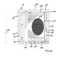
- the stator for linear motors comprises at least an inner yoke 2 and at least an outer yoke 3 that are so arranged as to define an air gap 4 therebetween.
- at least one of said yokes 2 and 3 comprises a magnetic member 5, 6 formed of at least a sheet-metal strip 7 that is coiled up, i.e. wound on itself about a longitudinal axis 8.
- the magnetic member 5, 6 is in this way constituted essentially by a plurality of layers 9 of the sheet-metal strip 7, which lie radially upon each other relative to said longitudinal axis 8.
- the stator has a cylindrical configuration developing around a central axis 10 of a linear motor, in which the outer yoke 3 is arranged coaxially around the inner yoke 2.
- the yokes 2, 3 are sized such that between the outer cylindrical surface of the inner yoke 2 and the inner cylindrical surface of the outer yoke 3 there is formed the air gap 4, within which there is arranged, in a generally known manner, the moving member (not shown) of the electric motor.
- the inner yoke 2 is formed integrally of a magnetic member 5, which is comprised of a sheet-metal strip 7, of a magnetic material, that is coiled up, i.e. wound on itself about a longitudinal axis 8, so as to form a cylindrical body whose axis coincides with said longitudinal axis 8.
- This cylindrical body has a side wall that is in this way constituted by a plurality of layers 9 of the sheet-metal strip 7, which lie annularly upon each other in a radial direction relative to said longitudinal axis 8.
- the longitudinal axis 8 of the inner yoke 2 comes to coincide with the central axis 10 such that the inner yoke 2, which is hollow, is adapted to receive and accommodate a cylinder/piston structure, in which the piston is capable of being slidably driven by the moving member of the linear motor, thereby defining a linear compressor, as this shall be explained in greater detail further on.
- the inner yoke 2 is shown to feature a circular and, in particular, spiral-like cross-sectional geometry relative to the longitudinal axis 8, it will nonetheless be readily appreciated that various other configurations may be contemplated in this connection, such as for instance a square or, more generally, polygonal cross-sectional shape.
- the outer yoke 3 which is arranged coaxially around the inner yoke 2, is itself given a cylindrical conformation, wherein its axis is centred on the central axis 10.
- the cross-section of the outer yoke 3, along the central axis 10, has a substantially C-shaped configuration, so as to form an annular cavity 11, in which a coil 12 of conductive material is wound.
- the outer yoke 3 comprises a magnetic member 3 formed of a sheet-metal strip 7, of a magnetic material, that is coiled up, i.e. wound on itself about a longitudinal axis 8, so as to form a cylindrical body whose axis coincides with said longitudinal axis 8.
- This cylindrical body has a side wall that is in this way constituted by a plurality of layers 9 of the sheet-metal strip 7, which lie annularly upon each other in a radial direction relative to said longitudinal axis 8.
- the magnetic member 6 forms the cylindrical wall of the outer yoke 3.
- the outer yoke 3 further comprises a first circular crown 13 and a second circular crown 14, which are associated on top and at the bottom, respectively, to the magnetic member 6 to form the annular cavity 11.
- Each one of said circular crowns 13, 14 is formed of a number of magnetic laminations 16, which are stacked upon and locked to each other by means of pegs 15.
- the laminations 16 are shaped such that the circular crowns 13, 14 feature a circular outer rim having a lower-profiled cross-section forming an annular abutment step 17, by means of which the circular crowns 13, 14 are capable of being snap-fitted onto the magnetic member 6.
- the outer yoke 3 also comprises a first magnetic ring 18 and a second magnetic ring 19 that are associated to the upper circular crown 13 and the lower circular crown 14, respectively, in such a manner as to face each other and be accommodated inside the cavity 11 formed by the crowns 13, 14 and the magnetic member 6.
- the rings 18 and 19 have a convergingly profiled cross-section so as to be able to substantially close and seal the annular cavity 11, thereby forming the pole shoes of the linear motor.
- the rings are of solid magnetic material having a triangular cross-section.
- the rings 18 and 19 are held in position by means of properly shaped members (not shown) that are used to electrically insulate the conductive coil 12 inside the annular slot 11 from the magnetic walls of the outer yoke 3.
- the magnetic flux induced by the current applied in the coil 12 passes across the stator in such a manner as to flow parallelly through the layers 9 that form the magnetic members 5 and 6, and parallelly through the laminations 16 that form the upper and lower circular crowns 13 and 14.
- this allows eddy-current losses in the yokes 2 and 3to be kept within acceptable limits, wherein said losses would on the contrary be quite high in the case that the stator is simply made with members of solid material without stacked layers.
- the pathway followed by the magnetic flux moving across the stator is closed by a cylindrical permanent magnet, which the moving member arranged in the air gap 4 is provided with.
- the pole shoes which are formed by the rings 18 and 19 and the inner periphery of the circular crowns 13 and 14, take polarities of an alternately opposite sign, and the resulting attractive and repulsive magnetic force acting on the permanent magnet generates a thrust that is in a proportion with the intensity of the current in the coil 12 and the density of the magnetic flux in the permanent magnet, so as to cause the moving member to reciprocatingly displace in the direction of the central axis 10 in a manner that is synchronous with the frequency of the alternating current being applied.
- the linear motor that comprises a stator according to the present invention is adapted to be applied in a linear compressor.
- Such linear compressor compresses a gas by means of a piston driven by the moving member of the linear motor.
- the piston slides reciprocatingly in the direction of the central axis 10 inside a cylinder that is arranged in the hollow portion of the inner yoke 2 and is in communication with a gas compression chamber.
- the stator according to the present invention is provided with extremely compact magnetic yokes of a cylindrical configuration, without any of the void spaces characterizing prior-art yokes in general, whereby the available volume is used to a maximum extent and the possibility is given for linear motors to be made, which are definitely more compact in size than those currently available on the market and, therefore, definitely more advantageous in view of an application thereof in refrigeration and air-conditioning compressors.
- stator further allows a smaller amount of magnetic material - which is largely known to be quite expensive - to be actually used in manufacturing the same stator.
- stator according to the present invention enables the use of laminations having particularly shaped contours to be reduced to a considerable extent, thereby reducing the amount of magnetic material being wasted due to manufacturing scraps.
- stator according to the present invention may be subject to a number of modifications and variants, and may be used in conjunction with a number of different applications, without departing from the scope of the present invention. Also, all items described in conjunction therewith may be replaced by technically equivalent elements.
Landscapes
- Engineering & Computer Science (AREA)
- Power Engineering (AREA)
- Linear Motors (AREA)
- Iron Core Of Rotating Electric Machines (AREA)
Applications Claiming Priority (2)
| Application Number | Priority Date | Filing Date | Title |
|---|---|---|---|
| ITPN20040026 ITPN20040026A1 (it) | 2004-04-23 | 2004-04-23 | Statore per motore lineare |
| ITPN20040026 | 2004-04-23 |
Publications (4)
| Publication Number | Publication Date |
|---|---|
| EP1589634A2 true EP1589634A2 (de) | 2005-10-26 |
| EP1589634A3 EP1589634A3 (de) | 2009-09-02 |
| EP1589634B1 EP1589634B1 (de) | 2015-05-20 |
| EP1589634B8 EP1589634B8 (de) | 2015-07-01 |
Family
ID=34939290
Family Applications (1)
| Application Number | Title | Priority Date | Filing Date |
|---|---|---|---|
| EP05102962.7A Ceased EP1589634B8 (de) | 2004-04-23 | 2005-04-14 | Stator eines Hubkolbenmotors |
Country Status (2)
| Country | Link |
|---|---|
| EP (1) | EP1589634B8 (de) |
| IT (1) | ITPN20040026A1 (de) |
Family Cites Families (4)
| Publication number | Priority date | Publication date | Assignee | Title |
|---|---|---|---|---|
| DE2630806A1 (de) * | 1976-07-08 | 1978-01-12 | Siemens Ag | Geblechtes staenderjoch elektrischer maschinen |
| JPH10146037A (ja) * | 1996-11-13 | 1998-05-29 | Matsushita Refrig Co Ltd | リニアモータ |
| DE69907801T2 (de) * | 1998-04-28 | 2004-03-11 | Matsushita Refrigeration Co., Higashiosaka | Linearmotor und linearer Kompressor |
| KR100396786B1 (ko) * | 2001-10-30 | 2003-09-02 | 엘지전자 주식회사 | 왕복동식 모터의 고정자 구조 |
-
2004
- 2004-04-23 IT ITPN20040026 patent/ITPN20040026A1/it unknown
-
2005
- 2005-04-14 EP EP05102962.7A patent/EP1589634B8/de not_active Ceased
Also Published As
| Publication number | Publication date |
|---|---|
| ITPN20040026A1 (it) | 2004-07-23 |
| EP1589634B1 (de) | 2015-05-20 |
| EP1589634A3 (de) | 2009-09-02 |
| EP1589634B8 (de) | 2015-07-01 |
Similar Documents
| Publication | Publication Date | Title |
|---|---|---|
| US7049925B2 (en) | Linear actuator | |
| CN210183197U (zh) | 横向磁通型线性马达和具有所述马达的线性压缩机 | |
| JP7360296B2 (ja) | 筒型リニアモータ | |
| US7215047B2 (en) | Linear motor and linear compressor including said motor | |
| JP2003143826A (ja) | 往復動式モータ | |
| CN112219339A (zh) | 用于旋转电机的定子 | |
| EP1374375B1 (de) | Pendelmotor | |
| EP1493221A1 (de) | Linearmotor und von diesem motor angetriebener verdichter | |
| EP1589634B1 (de) | Stator eines Hubkolbenmotors | |
| JP3754404B2 (ja) | 往復動式モータの構造及びその製造方法 | |
| JP3602818B2 (ja) | 往復動式モータの固定子の構造 | |
| KR100539813B1 (ko) | 리니어 모터용 스테이터 조립 구조 및 그 제작 방법 | |
| CN109639091B (zh) | 直线电机及压缩机 | |
| JP3851012B2 (ja) | リニア振動モータ | |
| EP2102974B1 (de) | Linearmotor für einen linearverdichter | |
| KR101983050B1 (ko) | 리니어 모터 및 이를 포함하는 리니어 압축기 | |
| KR0162425B1 (ko) | 리니어 압축기의 고정자 구조 | |
| KR100234744B1 (ko) | 리니어 모터구조 | |
| KR100360255B1 (ko) | 리니어 모터의 손실 저감구조 | |
| JP2009027921A (ja) | リニアアクチュエータ | |
| KR0112301Y1 (ko) | 선형압축기 | |
| KR100214640B1 (ko) | 리니어 압축기의 모터구조 | |
| KR100378809B1 (ko) | 멀티형 리니어 모터 | |
| KR100186477B1 (ko) | 밀폐형 선형압축기의 리니어 모터구조 | |
| KR100677255B1 (ko) | 왕복동식 모터의 고정자 구조 |
Legal Events
| Date | Code | Title | Description |
|---|---|---|---|
| PUAI | Public reference made under article 153(3) epc to a published international application that has entered the european phase |
Free format text: ORIGINAL CODE: 0009012 |
|
| AK | Designated contracting states |
Kind code of ref document: A2 Designated state(s): AT BE BG CH CY CZ DE DK EE ES FI FR GB GR HU IE IS IT LI LT LU MC NL PL PT RO SE SI SK TR |
|
| AX | Request for extension of the european patent |
Extension state: AL BA HR LV MK YU |
|
| PUAL | Search report despatched |
Free format text: ORIGINAL CODE: 0009013 |
|
| AK | Designated contracting states |
Kind code of ref document: A3 Designated state(s): AT BE BG CH CY CZ DE DK EE ES FI FR GB GR HU IE IS IT LI LT LU MC NL PL PT RO SE SI SK TR |
|
| AX | Request for extension of the european patent |
Extension state: AL BA HR LV MK YU |
|
| 17P | Request for examination filed |
Effective date: 20091005 |
|
| 17Q | First examination report despatched |
Effective date: 20091109 |
|
| AKX | Designation fees paid |
Designated state(s): DE |
|
| RAP1 | Party data changed (applicant data changed or rights of an application transferred) |
Owner name: ACC COMPRESSORS S.P.A. |
|
| REG | Reference to a national code |
Ref country code: DE Ref legal event code: R079 Ref document number: 602005046576 Country of ref document: DE Free format text: PREVIOUS MAIN CLASS: H02K0001120000 Ipc: H02K0001140000 |
|
| GRAP | Despatch of communication of intention to grant a patent |
Free format text: ORIGINAL CODE: EPIDOSNIGR1 |
|
| RIC1 | Information provided on ipc code assigned before grant |
Ipc: H02K 33/16 20060101ALI20141022BHEP Ipc: H02K 1/14 20060101AFI20141022BHEP |
|
| INTG | Intention to grant announced |
Effective date: 20141114 |
|
| GRAS | Grant fee paid |
Free format text: ORIGINAL CODE: EPIDOSNIGR3 |
|
| GRAA | (expected) grant |
Free format text: ORIGINAL CODE: 0009210 |
|
| AK | Designated contracting states |
Kind code of ref document: B1 Designated state(s): DE |
|
| RAP2 | Party data changed (patent owner data changed or rights of a patent transferred) |
Owner name: ITALIA WANBO-ACC S.R.L. |
|
| REG | Reference to a national code |
Ref country code: DE Ref legal event code: R096 Ref document number: 602005046576 Country of ref document: DE Effective date: 20150702 Ref country code: DE Ref legal event code: R096 Ref document number: 602005046576 Country of ref document: DE |
|
| REG | Reference to a national code |
Ref country code: DE Ref legal event code: R097 Ref document number: 602005046576 Country of ref document: DE |
|
| PLBE | No opposition filed within time limit |
Free format text: ORIGINAL CODE: 0009261 |
|
| STAA | Information on the status of an ep patent application or granted ep patent |
Free format text: STATUS: NO OPPOSITION FILED WITHIN TIME LIMIT |
|
| 26N | No opposition filed |
Effective date: 20160223 |
|
| PGFP | Annual fee paid to national office [announced via postgrant information from national office to epo] |
Ref country code: DE Payment date: 20220920 Year of fee payment: 18 |
|
| REG | Reference to a national code |
Ref country code: DE Ref legal event code: R119 Ref document number: 602005046576 Country of ref document: DE |
|
| PG25 | Lapsed in a contracting state [announced via postgrant information from national office to epo] |
Ref country code: DE Free format text: LAPSE BECAUSE OF NON-PAYMENT OF DUE FEES Effective date: 20231103 |