EP1589632A2 - Integrated inverter unit for a motor-generator - Google Patents
Integrated inverter unit for a motor-generator Download PDFInfo
- Publication number
- EP1589632A2 EP1589632A2 EP05007951A EP05007951A EP1589632A2 EP 1589632 A2 EP1589632 A2 EP 1589632A2 EP 05007951 A EP05007951 A EP 05007951A EP 05007951 A EP05007951 A EP 05007951A EP 1589632 A2 EP1589632 A2 EP 1589632A2
- Authority
- EP
- European Patent Office
- Prior art keywords
- electric machine
- rotating electric
- circuit
- channel mos
- mos semiconductor
- Prior art date
- Legal status (The legal status is an assumption and is not a legal conclusion. Google has not performed a legal analysis and makes no representation as to the accuracy of the status listed.)
- Withdrawn
Links
Images


Classifications
-
- F—MECHANICAL ENGINEERING; LIGHTING; HEATING; WEAPONS; BLASTING
- F02—COMBUSTION ENGINES; HOT-GAS OR COMBUSTION-PRODUCT ENGINE PLANTS
- F02N—STARTING OF COMBUSTION ENGINES; STARTING AIDS FOR SUCH ENGINES, NOT OTHERWISE PROVIDED FOR
- F02N11/00—Starting of engines by means of electric motors
- F02N11/04—Starting of engines by means of electric motors the motors being associated with current generators
-
- B—PERFORMING OPERATIONS; TRANSPORTING
- B60—VEHICLES IN GENERAL
- B60K—ARRANGEMENT OR MOUNTING OF PROPULSION UNITS OR OF TRANSMISSIONS IN VEHICLES; ARRANGEMENT OR MOUNTING OF PLURAL DIVERSE PRIME-MOVERS IN VEHICLES; AUXILIARY DRIVES FOR VEHICLES; INSTRUMENTATION OR DASHBOARDS FOR VEHICLES; ARRANGEMENTS IN CONNECTION WITH COOLING, AIR INTAKE, GAS EXHAUST OR FUEL SUPPLY OF PROPULSION UNITS IN VEHICLES
- B60K6/00—Arrangement or mounting of plural diverse prime-movers for mutual or common propulsion, e.g. hybrid propulsion systems comprising electric motors and internal combustion engines
- B60K6/20—Arrangement or mounting of plural diverse prime-movers for mutual or common propulsion, e.g. hybrid propulsion systems comprising electric motors and internal combustion engines the prime-movers consisting of electric motors and internal combustion engines, e.g. HEVs
- B60K6/22—Arrangement or mounting of plural diverse prime-movers for mutual or common propulsion, e.g. hybrid propulsion systems comprising electric motors and internal combustion engines the prime-movers consisting of electric motors and internal combustion engines, e.g. HEVs characterised by apparatus, components or means specially adapted for HEVs
- B60K6/26—Arrangement or mounting of plural diverse prime-movers for mutual or common propulsion, e.g. hybrid propulsion systems comprising electric motors and internal combustion engines the prime-movers consisting of electric motors and internal combustion engines, e.g. HEVs characterised by apparatus, components or means specially adapted for HEVs characterised by the motors or the generators
-
- B—PERFORMING OPERATIONS; TRANSPORTING
- B60—VEHICLES IN GENERAL
- B60K—ARRANGEMENT OR MOUNTING OF PROPULSION UNITS OR OF TRANSMISSIONS IN VEHICLES; ARRANGEMENT OR MOUNTING OF PLURAL DIVERSE PRIME-MOVERS IN VEHICLES; AUXILIARY DRIVES FOR VEHICLES; INSTRUMENTATION OR DASHBOARDS FOR VEHICLES; ARRANGEMENTS IN CONNECTION WITH COOLING, AIR INTAKE, GAS EXHAUST OR FUEL SUPPLY OF PROPULSION UNITS IN VEHICLES
- B60K6/00—Arrangement or mounting of plural diverse prime-movers for mutual or common propulsion, e.g. hybrid propulsion systems comprising electric motors and internal combustion engines
- B60K6/20—Arrangement or mounting of plural diverse prime-movers for mutual or common propulsion, e.g. hybrid propulsion systems comprising electric motors and internal combustion engines the prime-movers consisting of electric motors and internal combustion engines, e.g. HEVs
- B60K6/42—Arrangement or mounting of plural diverse prime-movers for mutual or common propulsion, e.g. hybrid propulsion systems comprising electric motors and internal combustion engines the prime-movers consisting of electric motors and internal combustion engines, e.g. HEVs characterised by the architecture of the hybrid electric vehicle
- B60K6/48—Parallel type
-
- B—PERFORMING OPERATIONS; TRANSPORTING
- B60—VEHICLES IN GENERAL
- B60W—CONJOINT CONTROL OF VEHICLE SUB-UNITS OF DIFFERENT TYPE OR DIFFERENT FUNCTION; CONTROL SYSTEMS SPECIALLY ADAPTED FOR HYBRID VEHICLES; ROAD VEHICLE DRIVE CONTROL SYSTEMS FOR PURPOSES NOT RELATED TO THE CONTROL OF A PARTICULAR SUB-UNIT
- B60W10/00—Conjoint control of vehicle sub-units of different type or different function
- B60W10/04—Conjoint control of vehicle sub-units of different type or different function including control of propulsion units
- B60W10/08—Conjoint control of vehicle sub-units of different type or different function including control of propulsion units including control of electric propulsion units, e.g. motors or generators
-
- F—MECHANICAL ENGINEERING; LIGHTING; HEATING; WEAPONS; BLASTING
- F02—COMBUSTION ENGINES; HOT-GAS OR COMBUSTION-PRODUCT ENGINE PLANTS
- F02N—STARTING OF COMBUSTION ENGINES; STARTING AIDS FOR SUCH ENGINES, NOT OTHERWISE PROVIDED FOR
- F02N11/00—Starting of engines by means of electric motors
- F02N11/08—Circuits specially adapted for starting of engines
- F02N11/0859—Circuits specially adapted for starting of engines specially adapted to the type of the starter motor or integrated into it
-
- H—ELECTRICITY
- H02—GENERATION; CONVERSION OR DISTRIBUTION OF ELECTRIC POWER
- H02J—ELECTRIC POWER NETWORKS; CIRCUIT ARRANGEMENTS OR SYSTEMS FOR SUPPLYING OR DISTRIBUTING ELECTRIC POWER; SYSTEMS FOR STORING ELECTRIC ENERGY
- H02J7/00—Circuit arrangements for charging or discharging batteries or for supplying loads from batteries
- H02J7/14—Circuit arrangements for charging or discharging batteries or for supplying loads from batteries for charging batteries from dynamo-electric generators driven at varying speed, e.g. on vehicle
- H02J7/1469—Regulation of the charging current or voltage otherwise than by variation of field
- H02J7/1492—Regulation of the charging current or voltage otherwise than by variation of field by means of controlling devices between the generator output and the battery
-
- H—ELECTRICITY
- H02—GENERATION; CONVERSION OR DISTRIBUTION OF ELECTRIC POWER
- H02M—APPARATUS FOR CONVERSION BETWEEN AC AND AC, BETWEEN AC AND DC, OR BETWEEN DC AND DC, AND FOR USE WITH MAINS OR SIMILAR POWER SUPPLY SYSTEMS; CONVERSION OF DC OR AC INPUT POWER INTO SURGE OUTPUT POWER; CONTROL OR REGULATION THEREOF
- H02M7/00—Conversion of AC power input into DC power output; Conversion of DC power input into AC power output
- H02M7/003—Constructional details, e.g. physical layout, assembly, wiring or busbar connections
-
- H—ELECTRICITY
- H10—SEMICONDUCTOR DEVICES; ELECTRIC SOLID-STATE DEVICES NOT OTHERWISE PROVIDED FOR
- H10W—GENERIC PACKAGES, INTERCONNECTIONS, CONNECTORS OR OTHER CONSTRUCTIONAL DETAILS OF DEVICES COVERED BY CLASS H10
- H10W72/00—Interconnections or connectors in packages
- H10W72/60—Strap connectors, e.g. thick copper clips for grounding of power devices
-
- F—MECHANICAL ENGINEERING; LIGHTING; HEATING; WEAPONS; BLASTING
- F02—COMBUSTION ENGINES; HOT-GAS OR COMBUSTION-PRODUCT ENGINE PLANTS
- F02D—CONTROLLING COMBUSTION ENGINES
- F02D41/00—Electrical control of supply of combustible mixture or its constituents
- F02D41/20—Output circuits, e.g. for controlling currents in command coils
- F02D2041/2068—Output circuits, e.g. for controlling currents in command coils characterised by the circuit design or special circuit elements
- F02D2041/2075—Type of transistors or particular use thereof
-
- F—MECHANICAL ENGINEERING; LIGHTING; HEATING; WEAPONS; BLASTING
- F02—COMBUSTION ENGINES; HOT-GAS OR COMBUSTION-PRODUCT ENGINE PLANTS
- F02N—STARTING OF COMBUSTION ENGINES; STARTING AIDS FOR SUCH ENGINES, NOT OTHERWISE PROVIDED FOR
- F02N11/00—Starting of engines by means of electric motors
- F02N11/08—Circuits specially adapted for starting of engines
- F02N11/0814—Circuits specially adapted for starting of engines comprising means for controlling automatic idle-start-stop
-
- F—MECHANICAL ENGINEERING; LIGHTING; HEATING; WEAPONS; BLASTING
- F02—COMBUSTION ENGINES; HOT-GAS OR COMBUSTION-PRODUCT ENGINE PLANTS
- F02N—STARTING OF COMBUSTION ENGINES; STARTING AIDS FOR SUCH ENGINES, NOT OTHERWISE PROVIDED FOR
- F02N11/00—Starting of engines by means of electric motors
- F02N11/08—Circuits specially adapted for starting of engines
- F02N2011/0881—Components of the circuit not provided for by previous groups
- F02N2011/0896—Inverters for electric machines, e.g. starter-generators
-
- H—ELECTRICITY
- H10—SEMICONDUCTOR DEVICES; ELECTRIC SOLID-STATE DEVICES NOT OTHERWISE PROVIDED FOR
- H10W—GENERIC PACKAGES, INTERCONNECTIONS, CONNECTORS OR OTHER CONSTRUCTIONAL DETAILS OF DEVICES COVERED BY CLASS H10
- H10W72/00—Interconnections or connectors in packages
- H10W72/071—Connecting or disconnecting
- H10W72/076—Connecting or disconnecting of strap connectors
- H10W72/07651—Connecting or disconnecting of strap connectors characterised by changes in properties of the strap connectors during connecting
- H10W72/07652—Connecting or disconnecting of strap connectors characterised by changes in properties of the strap connectors during connecting changes in structures or sizes
-
- H—ELECTRICITY
- H10—SEMICONDUCTOR DEVICES; ELECTRIC SOLID-STATE DEVICES NOT OTHERWISE PROVIDED FOR
- H10W—GENERIC PACKAGES, INTERCONNECTIONS, CONNECTORS OR OTHER CONSTRUCTIONAL DETAILS OF DEVICES COVERED BY CLASS H10
- H10W72/00—Interconnections or connectors in packages
- H10W72/60—Strap connectors, e.g. thick copper clips for grounding of power devices
- H10W72/621—Structures or relative sizes of strap connectors
- H10W72/627—Multiple strap connectors having different structures or shapes
-
- H—ELECTRICITY
- H10—SEMICONDUCTOR DEVICES; ELECTRIC SOLID-STATE DEVICES NOT OTHERWISE PROVIDED FOR
- H10W—GENERIC PACKAGES, INTERCONNECTIONS, CONNECTORS OR OTHER CONSTRUCTIONAL DETAILS OF DEVICES COVERED BY CLASS H10
- H10W72/00—Interconnections or connectors in packages
- H10W72/851—Dispositions of multiple connectors or interconnections
- H10W72/853—On the same surface
- H10W72/871—Bond wires and strap connectors
-
- H—ELECTRICITY
- H10—SEMICONDUCTOR DEVICES; ELECTRIC SOLID-STATE DEVICES NOT OTHERWISE PROVIDED FOR
- H10W—GENERIC PACKAGES, INTERCONNECTIONS, CONNECTORS OR OTHER CONSTRUCTIONAL DETAILS OF DEVICES COVERED BY CLASS H10
- H10W72/00—Interconnections or connectors in packages
- H10W72/90—Bond pads, in general
- H10W72/921—Structures or relative sizes of bond pads
- H10W72/926—Multiple bond pads having different sizes
-
- H—ELECTRICITY
- H10—SEMICONDUCTOR DEVICES; ELECTRIC SOLID-STATE DEVICES NOT OTHERWISE PROVIDED FOR
- H10W—GENERIC PACKAGES, INTERCONNECTIONS, CONNECTORS OR OTHER CONSTRUCTIONAL DETAILS OF DEVICES COVERED BY CLASS H10
- H10W90/00—Package configurations
- H10W90/701—Package configurations characterised by the relative positions of pads or connectors relative to package parts
- H10W90/731—Package configurations characterised by the relative positions of pads or connectors relative to package parts of die-attach connectors
- H10W90/734—Package configurations characterised by the relative positions of pads or connectors relative to package parts of die-attach connectors between a chip and a stacked insulating package substrate, interposer or RDL
-
- H—ELECTRICITY
- H10—SEMICONDUCTOR DEVICES; ELECTRIC SOLID-STATE DEVICES NOT OTHERWISE PROVIDED FOR
- H10W—GENERIC PACKAGES, INTERCONNECTIONS, CONNECTORS OR OTHER CONSTRUCTIONAL DETAILS OF DEVICES COVERED BY CLASS H10
- H10W90/00—Package configurations
- H10W90/701—Package configurations characterised by the relative positions of pads or connectors relative to package parts
- H10W90/761—Package configurations characterised by the relative positions of pads or connectors relative to package parts of strap connectors
- H10W90/764—Package configurations characterised by the relative positions of pads or connectors relative to package parts of strap connectors between a chip and a stacked insulating package substrate, interposer or RDL
-
- Y—GENERAL TAGGING OF NEW TECHNOLOGICAL DEVELOPMENTS; GENERAL TAGGING OF CROSS-SECTIONAL TECHNOLOGIES SPANNING OVER SEVERAL SECTIONS OF THE IPC; TECHNICAL SUBJECTS COVERED BY FORMER USPC CROSS-REFERENCE ART COLLECTIONS [XRACs] AND DIGESTS
- Y02—TECHNOLOGIES OR APPLICATIONS FOR MITIGATION OR ADAPTATION AGAINST CLIMATE CHANGE
- Y02T—CLIMATE CHANGE MITIGATION TECHNOLOGIES RELATED TO TRANSPORTATION
- Y02T10/00—Road transport of goods or passengers
- Y02T10/60—Other road transportation technologies with climate change mitigation effect
- Y02T10/62—Hybrid vehicles
-
- Y—GENERAL TAGGING OF NEW TECHNOLOGICAL DEVELOPMENTS; GENERAL TAGGING OF CROSS-SECTIONAL TECHNOLOGIES SPANNING OVER SEVERAL SECTIONS OF THE IPC; TECHNICAL SUBJECTS COVERED BY FORMER USPC CROSS-REFERENCE ART COLLECTIONS [XRACs] AND DIGESTS
- Y02—TECHNOLOGIES OR APPLICATIONS FOR MITIGATION OR ADAPTATION AGAINST CLIMATE CHANGE
- Y02T—CLIMATE CHANGE MITIGATION TECHNOLOGIES RELATED TO TRANSPORTATION
- Y02T10/00—Road transport of goods or passengers
- Y02T10/60—Other road transportation technologies with climate change mitigation effect
- Y02T10/70—Energy storage systems for electromobility, e.g. batteries
Definitions
- the present invention relates to a vehicle rotating electric machine to be mounted on a vehicle.
- the idling stop system for stopping an engine temporarily when the automobile are stopping such as waiting at a red light.
- the idling stop system provides an engine start system including, for example, a motor and an inverter device, separately from a starter.
- the motor is disposed in proximity to the engine, and transmits a driving force to the engine through a clutch and a belt at the time of restarting the engine.
- the inverter device since the inverter device has a large number of electronic parts that are low in the durability at high temperature, it is necessary that the inverter device is separated and arranged at a position that avoids a high temperature environment in the vicinity of the engine.
- an alternator (hereinafter also referred to as "inverter built-in alternator") which is equipped with a three-phase bridge converter circuit using MOS (metal oxide semiconductor) elements and a control circuit for the three-phase bridge converter circuit to enable motor drive.
- the inverter built-in alternator has an inverter circuit in which a rectifier diode of a normal vehicle alternator is replaced by a MOS element.
- the conventional large current output inverter has the three-phase bridge converter circuit made up of an N-channel MOSFET (metal oxide semiconductor field effect transistor) which is low in the on-resistance, there is provided a wiring layout in which the MOSFET at the higher side and the MOSFET at the lower side are connected to conductor plates that are different in the potential. As a result, because the two conductor plates thus insulated are required, the inverter circuit is prevented from being downsized.
- MOSFET metal oxide semiconductor field effect transistor
- the potential of the output terminal of the bridge circuit fluctuates roughly from the power potential to the ground potential according to the on/off states of the semiconductor switches at the higher side and the lower side, a power supply that provides a reference potential as the output terminal potential is required in the driver circuit of the MOSFET at the higher side in each of the phases (refer to Fig. 1.5).
- a large-capacity electrolytic capacitor is essential for the power supply of the driver circuit of the high-side MOSFET in order to hold the voltage.
- the electrolytic capacitor is larger in the volume than other electronic parts, and has such a characteristic that the electrostatic capacity is reduced and the deterioration such as an increase of the internal resistor is liable to occur under the high temperature environment. As a result, it is difficult to realize the inverter built-in alternator that requires the downsizing and the high-temperature durability in the inverter circuit that requires the electrolytic capacitor.
- the inverter built-in alternator requires the driver circuit, the minimum control circuits, a protector circuit and power supplies for those circuits in addition to the field current control circuit that is equipped in the conventional alternator having only a power generating function.
- the respective circuits are made up of the individual parts, it is very difficult from the viewpoint of sizes to realize that those circuits are equipped in the inverter built-in alternator.
- each of those circuits is made up of a circuit or a power supply which does not require the electrolytic capacitor from the viewpoint of the high-temperature resistant durability.
- the present invention provides a vehicle rotating electric machine that is capable of realizing that a power converter device is mounted on a rotating electric machine body by about the same built-structure as the conventional one.
- the present invention improves the property of mounting the power converter device onto the rotating electric machine body.
- the power control circuit is configured by connecting a plurality of the following series circuits in parallel, each of the series circuits may include a P-channel MOS semiconductor device disposed at a higher potential side and/or an N-channel MOS semiconductor device disposed at a lower potential side which are electrically connected in series.
- the present invention may integrate a plurality of electronic circuit elements that constitute a control circuit and/or a driver circuit in a control unit that controls the operation of the power control circuit.
- the inverter device can be downsized, there can be realized the vehicle rotating electric machine in which the inverter device is mounted on the rotating electric machine body by the substantially about same size as that of the general vehicle alternator.
- the idling stop function can be provided without remarkably changing the layout of the interior of an engine room.
- a motor-alternator 100 is a so-called inverter built-in vehicle rotating electric machine in which an inverter device 50 is integrated with a rotating electric machine body 1, and constitutes an electric power train of an automobile 200.
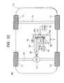
- the automobile 200 to which the motor-alternator 100 of the present invention is applied is a so-called hybrid automobile having both of an engine power train with an internal combustion engine as a power source and an electric power train with the motor-alternator 100 as a power source, as shown in Fig. 10.
- the engine power train is mainly used for a driving power source of the automobile 200.
- the electric power train is mainly used for the power source to make starting of the engine 120, and used for the electric power supply for the automobile 200.
- the automobile 200 having such an electric power train when the automobile stops such that the automobile waits at a red light in a state where the ignition key is on, the engine 120 automatically stops, and when the automobile starts, the electric power train automatically makes the engine start for starting of the vehicle.
- the automobile makes it possible to perform so-called idling stop driving which enables the fuel consumption of the automobile 200 to be improved and the exhaust emission to be reduced.
- a front axle 115 is rotatably supported at a front side of a vehicle body. Front wheels 111 and 112 are disposed at both ends of the front axle 115.
- a rear axle 116 is rotatably supported at a rear side of the vehicle body. Rear wheels 113 and 114 are disposed at both ends of the rear axle 116.
- a differential gear 117 that is a power sharing mechanism is disposed in the center of the front axle 115.
- the differential gear 117 shares a rotational driving force, which has been transmitted through a transmission 130 from the engine 120, to the right and left axle members of the front axle 115.
- the transmission 130 varies the rotational driving force of the engine 120 and transmits the varied driving force to the differential gear 117.
- the driving of the engine 120 is controlled by controlling the operations of accessories such as an injector that is a fuel control mechanism and a throttle valve that is an air flow rate control mechanism with an engine control device 140.
- the motor-alternator 100 is arranged within the engine room at the front of the vehicle body 110 together with the engine 120, and mounted to the side of the engine 120 and mechanically connected to the engine 120.
- the mechanical connection can be realized by looping a belt 170 over a pulley 120a disposed on a crank shaft of the engine 120 and a pulley 100a disposed on the rotary shaft of the motor-alternator 100.
- the motor-alternator 100 can transmit the rotational driving force to the engine 120, and can receive the rotational driving force from the engine 120.
- the electric power train of the automobile 200 is electrically connected to a 14 V vehicle power supply comprising a battery 150 as shown in Figs. 4 and 10, and gives a power generated by itself to the battery or receives a power from the 14 V vehicle power supply.
- the 14 V vehicle power supply is electrically connected with a starter as a starting device of the engine 120, and vehicle accessories machinery such as lamps, a car radio, and direction indicators not shown.
- a lead battery of an output voltage of about 12 V is used for the battery 150.
- the motor-alternator 100 is structured such that the inverter device 50 is integrated with the rotating electric machine 1.
- the rotating electric machine 1 is made up in common with conventional alternators mounted on the automobile as shown in Fig. 3. More specifically, the rotating electric machine 1 comprises a stator 2 having a stator winding 5 and a rotor 3 having a field winding 8 as shown in Fig. 4. A specific structure of the rotating electric machine body 1 will be described later with reference to Fig. 3.
- a three-phase alternating power, which is controlled by the inverter device 50, is supplied to the stator winding 5.
- a field current which is also controlled by the inverter device 50, is supplied to the field winding 8.
- a rotating magnetic field is generated by such three-phase alternating power and field current, and the rotor 3 rotates with respect to the stator 2.
- the motor generator 100 operates as an electric motor, and generates a rotational driving force for starting the engine 120.
- a field current is supplied to the field winding 8
- the rotor 3 rotates by the rotational driving force of the engine 120
- a voltage is induced in the stator winding 5.
- the motor-alternator 100 operates as an alternator, and generates a three-phase alternating power to charge the battery 150.
- a synchronous alternating rotating electric machine is used for the motor-alternator 100.
- an inductive alternating rotating electric machine may be used as the motor-alternator 100.
- the inverter device 50 is a power converter device that converts a DC power supplied from the battery 150 into a three-phase AC power, or converts a three-phase AC power obtained by the power generation of the motor-alternator 100 into a DC power. More specially, the inverter device 50 comprises a module unit 52 and a control unit 51 as shown in Fig. 4. The mounting structure of the inverter device 50 will be described later with reference to Fig. 1.
- the module unit 52 has a converter circuit 55 and a field circuit 56.
- the converter circuit 55 is a power control circuit that converts a DC power supplied from the battery 150 into a three-phase AC power, or converts a three-phase AC power supplied from the stator winding 5 into a DC power.
- the field circuit 56 is a field current control circuit that controls the field current supplied to the field winding 8 from the battery 150.
- the control unit 51 has a control circuit 53 and a driver circuit 54.
- the control circuit 53 is a control logic circuit that outputs, to the driver circuit 54, command signals to control the operation of the converter circuit 55 and the field circuit 56 according to a command signal from a host control device, for example, the engine control device 140, and various detection signals (feedback signals) related to a phase voltage of the motor-alternator 100 or the terminal voltage of the battery 150.
- the driver circuit 54 Upon receiving the command signal from the control circuit 53, the driver circuit 54 outputs the driving signals to operate the converter circuit 55 and the field circuit 56 to the converter circuit 55 and the field circuit 56.
- a voltage adjuster that has been mounted on the vehicle alternator up to now is integrated with the inverter device 50 to ensure a space where which the inverter deice 50 is mounted.
- control circuit 53 The respective structures of the control circuit 53, the driver circuit 54, the converter circuit 55 and the field circuit 56 in the inverter device 50 will be described in more detail.
- the converter circuit 55 converts the DC power into the three-phase AC power or the three-phase AC power into the DC power by the switching (on/off) operation of the switching semiconductor device.
- the switching semiconductor device may be MOSFETs (MOS field effect transistor) that are MOS (metal oxide semiconductor) elements, or an IGBT (insulated gate bipolar transistor). In this embodiment, MOSFETs in which respective diodes are incorporated are used for the switching semiconductor device.
- the converter circuit 55 is configured with a bridge circuit of 6 phases (3 phases X the number of stator windings:2) in which each thereof has a P-channel MOSFET and a N-channel MOSFET.
- a drain electrode of the P-channel MOSFET 64 and a drain of the N-channel MOSFET 65 are electrically connected to each other in series, on condition that the P-channel MOSFET 64 is disposed at a higher potential pole (positive pole) side, and the N-channel MOSFET 64 is disposed at a lower potential pole (negative pole) side.
- the bridge circuit of 6 Phases is configured for converter.
- a source electrode of the P-channel MOSFET 64 is electrically connected to the higher potential pole (positive pole) side in both poles of the battery 150.
- a source electrode of the N-channel MOSFET 65 is electrically connected to the lower potential pole (negative pole) side in both poles of the battery 150.
- Phase windings of the stator winding 5 respectively are electrically connected between the drain electrodes of the P-channel MOSFET 64 and the N-channel MOSFET 65. That is, a U-phase winding on one side of the stator winding 5 is electrically connected between the drain electrodes of the P-channel MOSFET 64U 1 and the N-channel MOSFET 65U 1 .
- a U-phase winding on the other side of the stator winding 5 is electrically connected between the drain electrodes of the P-channel MOSFET 64U 2 and the N-channel MOSFET 65U 2 .
- Corresponding driving signals A to L are inputted from the control unit 51 to the gate electrodes of the P-channel MOSFET 64 and the N-channel MOSFET 65.
- a voltage between the drain electrodes of the P-channel MOSFET 64 and the N-channel MOSFET 65 is inputted to the control unit 51 as a phase voltage signal.
- a voltage at a higher potential pole (positive pole) side in both poles of the battery 150 is inputted to the control unit 51 as a battery positive pole voltage signal.
- the field circuit 56 controls a field current that flows into the field winding 8 from the battery 150 due to the switching (on/off) operation of the switching semiconductor device.
- An N-channel MOSFET 69 is used for the switching element.
- the drain electrode of the N-channel MOSFET 69 is electrically connected to a negative pole end of the field winding 8 (a side opposite to the positive pole end connected to the higher potential (positive pole) side of the battery 150).
- a source electrode of the N-channel MOSFET 69 is electrically connected to the lower potential (negative pole) side of the battery 150.
- a driving signal T from the control unit 51 is inputted to a gate electrode of the N-channel MOSFET 69.
- a diode 68 is electrically connected between the drain electrodes of the N-channel MOSFET 69 and the higher potential (positive pole) side of the battery 150.
- the diode 68 is made up of a P-channel MOSFET which is in a forward direction toward the higher potential (positive pole) side of the battery 150 from the drain electrode side of the N-channel MOSFET 69.
- the control circuit 53 is a circuit that operates by a driving voltage of about 5 V, and includes plural control units as shown in Fig. 5.
- the driving voltage is applied from the driver circuit 54 which will be described later, and the driving voltage results from stepping down the voltage (about 12 V) of the battery 150.
- the control circuit 53 inputs a command signal from the engine control device 140 that is a host control device.
- the command signal from the engine control device 140 is a signal for operating the motor-alternator 100 as a motor, or a signal for operating the motor-alternator 100 as an alternator. Those signals are outputted according to the operation state of the vehicle.
- the engine control device 140 outputs a start signal for operating the motor-alternator 100 as the motor to the control circuit 53 when the off of the brake is detected.
- the transmission of the command signal from the engine control device 140 to the control circuit 53 is conducted by means of an LIN (local interconnect network) system which is one of the serial communication systems.
- the command signal from the engine control device 140 to the control circuit 53 through a LIN is inputted to a microprocessor (hereinafter referred to as "MP") 53d through an interface circuit 53f.
- MP 53d judges the operation mode of the motor-alternator 100 based on an inputted command signal, and outputs the operation commands to the respective control units according to the operation mode so that the respective control units execute given processing corresponding to the operation mode.
- the MP 53d reads program or data corresponding to the operation mode from a RAM 53m that is a memory device that can rewrite the stored information or a ROM 53n that is a memory device that can read the stored information, or writes the data in the RAM 53m.
- the MP 53d has an A/D converter 53k and a timer/counter 53e.
- the AD converter 53k converts an analog quantity such as a voltage or temperature inputted to the MP 53d into a digital quantity.
- a timer/counter 531 is used to, for example, measure a time width at which the command value is sequentially changed by the control program and a time interval in which the LIN communication is conducted.
- the MP 53d can detect the rotation speed of the motor-alternator 100, and can output the predetermined operation commands to the respective control units by comparing the sensed rotation speed with a predetermined rotation speed.
- the signal transmission between the engine control device 140 and the control circuit 53 is executed by using the LIN, thereby making it possible to reduce the number of communication lines between the engine control device 140 and the control circuit 53.
- the control unit has a motor control unit 53a, an alternator (synchronous rectifier) control unit 53b, and a filed control unit 53h.
- the motor control unit 53a When the motor-alternator 100 operates as the motor, the motor control unit 53a outputs voltage command signals to control the operation of the P-channel MOSFETs 64 and the N-channel MOSFETs 65 of the converter circuit 55.
- An operation command signal from the MP 53d, a rotation speed signal from the rotation speed calculating circuit 53e, and phase voltage signals c to h from the converter circuit 55 are inputted to the motor control 53a through the driver circuit 54.
- the rotation speed signal is calculated based on a sensed signal b from a rotation sensor 73.
- the motor control unit 53a outputs voltage command signals for controlling the operation of the P-channel MOSFETs 64 and the N-channel MOSFETs 65 according to the operation command signal from the MP 53d and based on the sensed signal b from the rotation sensor 73.
- the voltage command signals are to control the MOSFETs 64, 65 so that the motor-alternator 100 reaches a target rotation speed.
- the voltage command signals related to the P-channel MOSFETs 64 at the higher potential side are inputted to a switching circuit 53j.
- the voltage command signals related to the N-channel MOSFETs 65s at the lower potential side are inputted to a switching circuit 53i.
- the alternator (synchronous rectifier) control unit 53b When the motor-alternator 100 operates as the alternator, the alternator (synchronous rectifier) control unit 53b outputs voltage command signals to control the operation of the P-channel MOSFETs 64 and the N-channel MOSFETs 65 of the converter circuit 55.
- the operation command signal from the MP 53d, the phase voltage signals c to h from the converter circuit 55 via the driver circuit 54, a battery higher potential side voltage signal i from the converter circuit 55 via the driver circuit 54, and a battery lower potential side voltage signal j from the driver circuit 54, are inputted to the alternator (synchronous rectifier) control unit 53b.
- the alternator (synchronous rectifier) control unit 53b outputs voltage command signals for controlling of the operation of the P-channel MOSFETs 64 and the N-channel MOSFETs 65, in order to synchronously rectify the three-phase AC power from the motor-alternator 100 and convert the AC power into a DC power according to the operation command of the MP 53d.
- the alternator control unit 53b compares a voltage across both ends of the battery 150 with the inputted phase voltage values of the respective phases (in the case where the phase voltage is positive, the phase voltage value is compared with the battery higher potential side voltage, whereas in the case where the phase voltage is negative, the phase voltage value is compared with the battery lower potential side voltage).
- the alternator (synchronous rectifier) control unit 53b outputs voltage command signals for controlling the operation of the P-channel MOSFETs 64 and the N-channel MOSFETs 65 according to the comparison result being equal to or more than a predetermined voltage (forward voltage drop of the diode: about 0.7 V), or less.
- a predetermined voltage forward voltage drop of the diode: about 0.7 V
- the voltage command signals related to the P-channel MOSFETa 64 at the higher potential side are inputted to the switching circuit 53j.
- the voltage command signals related to the N-channel MOSFET 65 at the lower potential side are inputted to the switching circuit 53i.
- the field control unit 53h When the motor-alternator 100 operates as the motor or the alternator, the field control unit 53h outputs a voltage command signal to control the operation of the N-channel MOSFET 69.
- the N-channel MOSFET is used to pass a field current through a winding 8 of the field circuit 56.
- the operation command signal from the MP 53d and an abnormality signal from a detector/protector circuit unit 53c that will be described later, are inputted to the field control unit 53h.
- the field control unit 53h calculates a field current value based on the operation command from the MP 53d so that a predetermined torque is outputted from the motor-alternator 100.
- the field control unit 53h calculates a voltage command value based on the calculated field current value; then, it outputs the voltage command value as a voltage command signal for controlling the operation of the N-channel MOSFET 69.
- the field control unit 53h calculates a field current value according to the operation command of the MP 53d so that a predetermined electrical energy is outputted from the motor-alternator 100.
- the control unit 53h calculates the voltage command value based on the calculated field current value; then, the field control unit 53h outputs the voltage command value as the voltage command signal for controlling the operation of the N-channel MOSFET 69.
- the field control unit 53h outputs the voltage command signal to control the operation of the N-channel MOSFET 69 based on the abnormality signal from the detector/protector circuit unit 53c so that the amount of current flowing in the winding 8 is decreased.
- a voltage command signal x from the field control unit 53h is inputted to the driver circuit 54.
- the detector/protector circuit unit 53c is used to detect the generation of an over-voltage such as a damp surge voltage, an over-current or an over-temperature, and protect a switching element of the converter circuit 55 or the field circuit 56 from such over-voltage, over-current or over-temperature.
- An operation command signal from the MP 53d, phase voltage signals c to h from the converter circuit 55 via the driver circuit 54, a battery higher potential side voltage signal i from the converter circuit 55 via the driver circuit 54, and a battery lower potential side voltage signal j from the driver circuit 54, are inputted to the detector/protector circuit unit 53c.
- the detector/protector circuit unit 53c executes various abnormality detections on the basis of the operation command signal from the MP 53d.
- the detector/protector circuit unit 53c outputs the abnormality signal to the MP 53d and the field control unit 53h.
- the operation command signal is outputted to the switching circuit 53i so that the N-channel MOSFET 65 at the lower potential side of the converter circuit 55 should be turned off.
- the switching circuit 53j switches between the voltage command signals from the motor control unit 53a and the voltage command signals from the alternator (synchronous rectifier) control unit 53b according to the operation mode of the motor-alternator 100; and the switched signals are outputted. Those voltage command signals are used for controlling the operation of the P-channel MOSFET 64.
- the operation command signal from the MP 53d and the voltage command signals from the motor control unit 53a or the alternator (synchronous rectifier) control unit 53b, are inputted to the switching circuit 53j.
- the switching circuit 53j switches the outputs of the voltage command signals for the P-channel MOSFET 64 according to the operation command signal from the MP 53d, and outputs the switched voltage command signals to the driver circuit 54 as the voltage command signals j to q.
- the switching circuit 53i switches between the voltage command signals from the motor control unit 53a and the alternator (synchronous rectifier) control unit 53b according to the operation mode of the motor-alternator 100; and the switched signals are outputted. Those voltage command signals are used for controlling the operation of the N-channel MOSFET 65.
- the switching circuit 53i switches the outputs of the voltage command signals for the N-channel MOSFET 65 according to the operation command signal from the MP 53d, and outputs the voltage command signals to the driver circuit 54 as the voltage command signals r to w.
- the motor control unit 53a, the alternator (synchronous rectifier) control unit 53b, and the detector/protector circuit unit 53c are surrounded by a dotted line.
- Arrows indicative of signals that are commonly inputted to the motor control unit 53a, the alternator (synchronous rectifier) control unit 53b and the detector/protector control unit 53c are inputted to the box indicated by the dotted line.
- the number of arrows of the voltage command signals from the motor control unit 53a and the alternator (synchronous rectifier) control unit 53b, respectively, is equal to the number of P-channel MOSFETs 64 and N-channel MOSFETs 65, that is 12. In this embodiment, for simplification of the drawing, those arrows are indicated by one arrow. In addition, in this embodiment, in order to distinguish between power flows and signal flows, the power flows are indicated by solid lines, and the signal flows are indicated by dotted lines, respectively.
- the control circuit 53 is provided with a temperature sensor 53g. Also, a thermistor 57 is disposed in the converter circuit 55, a sensing signal from the termistor 57 is inputted to the control circuit 53. In the control circuit 53, any signal of the sensing signal from the temperature sensor 53g and the sensing signal from the thermistor 57 is selected and inputted to an A/D converter 53k. Then, the signal is converted into a digital signal and inputted to the MP 53d.
- the driver circuit 54 operates at an output voltage (about 12 V) of the battery 150, and as shown in Fig. 6, comprises driver units 54d 1 to 54d 12 , 54e, level converter circuits 54b, 54c, and a control power supply 54a.
- the control power supply 54a is electrically connected between both poles of the battery 150, and outputs a driving power of the control circuit 53.
- the control power supply 54a supplies a control power k resulting from stepping down the output voltage (about 12 V) of the battery 150 to about 5 V to the control circuit 53.
- the driver units 54d 1 to 54d 6 output driving signals to drive the P-channel MOSFET 64 corresponding to the converter circuit 55.
- the driver unit 54d 7 to 54d 12 output driving signals to turn on/off the N-channel MOSFET 65 corresponding to the converter circuit 55.
- the driver unit 54e outputs a driving signal to drive the N-channel MOSFET 65 of the field circuit 56.
- the voltage command signals 1 to q among the voltage command signals outputted from the control circuit 53, are increased in the potential level by the level converter circuit 54d and then inputted to the corresponding driver units 54d 1 to 54d 6 .
- the voltage command signals r to w are increased in the potential level by the level converter circuit 54d and then inputted to the corresponding driver units 54d 7 to 54d 12 .
- the voltage command signal x from the control circuit 53 is increased in the potential level by the level converter circuit 54c and then inputted to the driver unit 54e.
- the driver units 54d 1 to 54d 6 output the driving signals A to F to the gate electrode of the corresponding P-channel MOSFET 64 according to the inputted voltage command signals 1 to q.
- the driver units 54d 7 to 54d 12 output the driving signals G to L to the gate electrode of the corresponding N-channel MOSFET 65 according to the inputted voltage command signals r to w.
- the driver unit 54e outputs the driving signal T to the gate electrode of the corresponding N-channel MOSFET 65 according to the inputted voltage command signal x.
- the level converter circuit 54d drops the potential levels of the phase voltage signals M to R and the battery higher potential side voltage signal S from the converter circuit 55, and then output those signals to the control circuit 53 as the phase voltage signals c to h and the battery higher potential side voltage signal i.
- the level converter circuit 54b takes in the lower potential side voltage of the battery 150 as the battery lower potential side voltage signal, drops the potential level and outputs the voltage to the control circuit 53 as the battery lower potential side voltage signal j.
- Each of the driver units 54d 1 to 54d 12 is made up of a circuit including a transistor and a resistor, as shown in Fig. 9.
- a structure of a driver unit for one arm which consists of a P-channel MOSFET 64 and an N-channel MOSFET 65.
- the driver unit for driving the P-channel MOSFET 64 is made up of the following an off-circuit and an on-circuit.
- the off-circuit comprises a series circuit of a transistor 401 and a resistor 407, a series circuit of a transistor 402 and a resistor 408, and a series circuit of a transistor 403 and a resistor 409; and the off-cut circuit is formed by connecting these series circuits in parallel.
- the on-circuit is formed with a series circuit of a transistor 413 and a resistor 414.
- the driver unit for driving the N-channel MOSFET 65 is made up of the following an off-circuit and an on-circuit.
- the off-circuit comprises a series circuit of a transistor 404 and a resistor 410, a series circuit of a transistor 405 and a resistor 411, and a transistor 406 and a resistor 412; and the off-circuit is formed by connecting these series circuits in parallel.
- the on-circuit is formed with the series circuit of a transistor 415 and a resistor 416.
- each emitter electrode of the transistors 401-403 is electrically connected to a source electrode side of the P-channel MOSFET 64, and each end of the resistors 407-409 opposite to each collector electrode of the transistors 401-403 is electrically connected to a gate electrode side of the P-channel MOSFET 64.
- an emitter electrode of the transistor 413 is connected to a source electrode side of the N-channel MOSFET 65, and end of the resistor 414 opposite to a collector electrode of the transistor 413 is connected to a gate electrode side of the P-channel MOSFET 64.
- each emitter electrode of the transistors 404-406 is electrically connected to a source electrode side of the N-channel MOSFET 65, and each end of the resistors 410-412 opposite to each collector electrode side of the transistor 404-406 is electrically connected to a gate electrode side of the N-channel MOSFET 65.
- an emitter electrode side of the transistor 415 is electrically connected to a source electrode side of the P-channel MOSFET 64, and an end of the resistor 416 opposite to a collector electrode side of the transistor 415 is electrically connected to a gate electrode side of the N-channel MOSFET 65.
- the driver unit thus structured according to this embodiment, by changing the off signal applied to the base electrodes of the transistors 401 to 403 (off circuit of each P-channel MOSFET 64 switch), it possible to control a speed of drawing out the electric charges of the gate electrode of the P-channel MOSFET 64 according to the resistances of the resistors 407 to 409.
- the resistances of the resistors 407 to 409 are 10 ⁇ , 20 ⁇ and 40 ⁇
- the resistances in the off circuit of the P-channel MOSFET 64 can be adjusted in a wide range of about 6 to 40 ⁇ .
- the MOS elements for the converter circuit 55 are changed, the switching speed of that element can be readily changed.
- the off signal supplied to the base electrode of the transistors 401 to 403(off circuit of the P-channel MOSFET 64) can be readily changed over by changing of the variable of the memory.
- the program of the switching timing of the off signal that is applied to the base electrode of the transistors 401 to 403 it possible to perform soft switching for changing a speed depend on time at which the gate electric charges of the transistors 401 to 403 is drawn out. The same is applied to the N-channel MOSFET 65 side.
- reference numeral 2 denotes a stator.
- the stator 2 has a stator core 6 and a stator winding 5 installed on the stator core 6.
- the stator core 6 is formed of a cylindrical lamination core resulting from forming a plurality of annular core plates each of which is obtained by punching a thin silicon steel plate. The thickness of each of the core plates laminated at both ends of the lamination core in the axial direction is thicker than the core plates laminated in the middle portion in the axial direction.
- a core back (not shown) is formed on the outer peripheral portion of the stator core 6 is formed with.
- the core back is formed of a cylindrical core portion that is formed continuously in the circumferential direction, and is held between a front bracket 12 and a rear bracket 13 from both sides thereof in the axial direction.
- the stator 2 is supported at the inner side of the brackets.
- Plural teeth (not shown) are formed on the inner circumferential side of the core back which is an inner circumferential portion of the stator core 6.
- the teeth are dentate core portions that are so formed as to project toward an inner center side in the radial direction from the inner circumferential surface of the core back, and formed continuously in the axial direction along the inner circumferential surface of the core back.
- the plural teeth are at given intervals in the circumferential direction along the inner circumferential surface of the core back.
- the slots are space portions for receiving the winding conductors that constitute the stator winding 5, and formed continuously in the axial direction as with the teeth portion.
- Plural slots are arranged at predetermined intervals in the circumferential direction. Also, a side opposite to the core back of each slot is opened, and both ends of the slot in the axial direction are also opened.
- Each of the slots receives the winding conductor that constitutes the stator winding 5.
- Each of the winding conductors is formed by a rectangular wire or a circular wire.
- Each of the winding conductors projects outward from both ends of the stator core 6 in the axial direction to be connected to obtain a star connection.
- the stator winding 5 is formed of two three-phase windings that are electrically independent from each other.
- the rotor 3 is so disposed as to face the inner circumferential side of the stator 2 with a gap.
- a rotary shaft 9 is disposed on the center axis of the rotor 3.
- One end side of the rotary shaft 9 is supported rotatably by a bearing 14 at the center portion of the front bracket 12, and the other end side is supported by a bearing 15 at the center portion of the rear bracket 13.
- a portion of the rotary shaft 9 which faces the inner circumferential side of the stator 2 is fixed into a rotor core 7.
- the rotor core 7 is structured so that a pair of ungual-form magnetic pole cores face each other in the axial direction.
- the ungual-form magnetic pole cores have plural ungual-form magnetic poles that extend toward the centrifugal side in the radial direction from the cylindrical core portion, and have triangular or trapezoidal leading ends folded at right angles in directions along which those leading ends face each other.
- the ungual-form magnetic poles are arranged at given intervals in the rotational direction. In the case where the ungual-form magnetic poles face each other in the axial direction, the ungual-form magnetic poles are arranged between the respective ungual-form magnetic poles of the ungual-form magnetic pole cores that face each other.
- One of the ungual-form magnetic pole cores forms an N pole.
- the other magnetic pole forms an S pole.
- the rotor 3 has plural magnetic poles formed in such a manner that the polarity is alternately different in the rotational direction, that is, the N pole and the S pole are alternate.
- the field winding 8 is disposed on the outer circumference of the core portions which face the inner circumferential side of the leading portions of the ungual-form magnetic poles.
- One end of the rotary shaft 9 in the axial direction extends toward the outer side in the axial direction farther than the bearing 14.
- a pulley 100a is disposed on a portion that extends toward the outer side in the axial direction farther than the bearing 14 on one end of the rotary shaft 9.
- the pulley 100a is connected to a pulley 120a of the engine 120 through a belt (not shown).
- the other end of the rotary shaft 9 in the axial direction (the end portion on the rear bracket 13 side) extends toward the outer side in the axial direction farther than the bearing 15.
- a slip ring 17 is disposed on the outer circumferential surface of the portion that extends toward the outer side in the axial direction farther than the bearing 15 on the other end of the rotary shaft 9.
- the slip ring 17 is electrically connected to the field winding 8.
- the slip ring 17 is slidable in contact with a brush 16.
- the brush 16 supplies a field current to be supplied to the field winding 8 to the slip ring 17.
- a front fan 11 is attached onto one end of the ungual-form magnetic pole core (end portion on the front bracket 12 side) in the axial direction.
- a rear fan 10 is attached onto the other end of the ungual-form magnetic pole core (end portion on the rear bracket 13 side) in the axial direction.
- the front fan 11 and the rear fan 10 rotate together with the rotation of the rotor 3 so that an outside air to be a cooling medium is introduced into the interior of the machine from the exterior and then circulated within the machine, and the outside air that has finished the cooling function is exhausted toward the exterior from the interior of the machine.
- plural through-holes are provided at the front bracket 12 and the rear bracket 13 in order to introduce the outside air into the interior of the machine from the exterior and to exhaust the outside air toward the exterior from the interior of the machine.
- a space defined by module cases 62 and 63 is formed on one side of a side surface of the rear bracket 13 (a side opposite to the front bracket 12 side).
- An inverter device 50 is installed in the space.
- the module case 63 serves as a brush holder that holds the brush 16.
- a communication terminal 60 and a battery terminal 18 are exposed from the module case 62 toward the external.
- the rear bracket 13 is electrically connected to a chassis of the automobile 200.
- a positive pole side of the inverter device 50 is electrically connected to the battery terminal 18, and a negative pole (ground) side is electrically connected to the rear bracket 13.
- the above structure has the compatibility with the general vehicle alternator.
- the control circuit 53 including the converter circuit 55 and the control power supply 54a Concerning the structure of the control circuit 53 including the converter circuit 55 and the control power supply 54a, there are considerable two types.
- One of the converter circuits 55 may be formed of P-channel MOSFETs 64 and N-channel MOSFETs 65.
- Another may be formed of only the N-channel MOSFETs 65.
- both types thereof will be described in comparison.
- the N-channel semiconductor device is mainly used in order to reduce the loss of the semiconductor device at the on time.
- the control circuit 53 including the converter circuit 55 and the control power supply 54 is structured as shown in Fig.
- control circuit 53 including the converter circuit 55 and the control power supply 54a as in the latter is shown in Fig. 12.
- a potential between the higher potential and the lower potential can be supplied to the gate electrodes of each MOSFET relative to the higher potential side of the battery 150; and in MOSFETs of the lower potential side, the potential between the higher potential and each lower potential can be supplied to the gate electrodes of each MOSFET relative to the lower potential side (ground potential) of the battery 150; thereby making it possible to drive the respective MOSFETs.
- the high side power supply 300 for driving the MOSFET on the higher potential side is not required in the circuit shown in Fig. 1, whereas at least three high side power supplies 300 are required in the circuit shown in Fig. 12.
- an electrolyte capacitor that is relatively large in the electrostatic capacity is required in the high side power supply 300 in order to hold the voltage.
- the electrolyte capacitor suffers from a problem on the reliability under the high-temperature environment.
- a relationship between the lifetime of the electrolyte capacitor and the temperature is frequently expressed by the following relational expression that applies the Arrhenius law.
- L Lc*A ((Tc-T)/10) where L is the lifetime at the used temperature T, Lc is the lifetime at a reference temperature T c , T is the used temperature, T c is the reference temperature, and A is a temperature acceleration coefficient.
- the lifetime of the electrolyte capacitor means an increase in the internal resistance and a decrease in the capacitance.
- the circuit of this embodiment shown in Fig. 1 is effective. Also, there are a large number of MOSFETs that are driven by a power supply of about 10 V to 14 V. From this viewpoint, since the circuit structure of this embodiment shown in Fig. 1 can use the 14 V power supply mounted on a large number of vehicles as it is, the MOSFET is proper for the inverter built-in rotating electric machine that is applied to the 14 V power supply vehicle.
- an insulating substrate 66 is formed of a circuit board where electrically conductive plates 66b to 66d and an insulating plate 66a are put together.
- the insulating plate 66a is made of aluminum nitride, silicon nitride or alumina which is an insulating material that is excellent in the heat conductance.
- the conductive plates 66b and 66d of the insulating substrate 66 which also serve as wirings of the converter circuit, are divided into two pieces and insulated from each other in order to fix the MOSFETs at the higher potential side and the lower potential side.
- the mounting area can be reduced more than the circuit structure shown in Fig. 12 without the above-mentioned restriction.
- the importance of the temperature management of the MOS semiconductor that is a main heating part is high because the motor-alternator 100 is used under the high-temperature environments. In order to manage the temperature with higher precision, it is essential to locate a temperature sensing thermistor 57 on the conductive plate 66b on which the MOS semiconductor is fixed. In the circuit shown in Fig.
- two thermistors 57 are required because the conductive plates on which the MOS semiconductors at the higher potential side and the lower potential side are fixed are separated from each other.
- one thermistor 57 may be provided in the circuit structure according to this embodiment shown in Fig. 1. Even if an area necessary to locate the thermistor 57 is not taken into consideration, the circuit structure of this embodiment shown in Fig. 1 can reduce the mounting area more than the circuit structure shown in Fig. 12.
- this embodiment in which the circuit structure shown in Fig. 1 is applied, solves problems occurring when the inverter device 50 is integrally mounted on the rotating electric machine body 1, that is, problems such as the downsizing and the high-temperature durability.
- reference numeral 64 denotes each P-channel MOSFET
- 65 is each N-channel MOSFET
- 66 is an insulating substrate
- 61 is a radiation conductive plate
- 67 is an output terminal
- 70P and 70N are power supply wirings
- 71 is a positive pole side power terminal
- 72 is a control circuit board
- 51 is a control IC (control unit).
- reference numeral 60 denotes a communication terminal
- 74 is a wiring for connects the source electrode of the P-channel MOSFET 64 and the power supply wiring 70P
- 75 is a wiring that connects the source electrode of the N-channel MOSFET 65 and the radiation conductive plate 61
- 76 is a wiring that connects an electrically conductive plate of the insulating substrate 66 and the output terminal 67
- 73 is a rotation sensor
- 77 is a wiring that connects a P-channel MOSFET as a diode 68 and the power supply wiring 70P.
- reference numeral 78 denotes a wiring that connects the insulating substrate and the power supply wiring 70N
- 69 denotes a wiring that connects the source electrode of the N-channel MOSFET 69 and the radiation conductive plate 61
- 80 is an aluminum wire for connecting the control circuit board 72 to the 2-channel MOSFET 64 and the N-channel MOSFETs 65, 69, respectively.
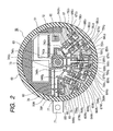
- the control unit 51 and the rotation sensor 73 are disposed in an upper half of a space within the module cases 62 and 63, and the module unit 52 is disposed in a lower half of the space.
- the drain electrodes of the P-channel MOSFET 64 and the N-channel MOSFET 65 are connected to the conductive plates of the insulating substrate 66 in which the conductive plates are bonded to the insulating plate.
- the source electrode of the P-channel MOSFET 64 and the power supply wiring 70P are connected by the wiring 74.
- the source electrode of the N-channel MOSFET 65 and the radiation conductive plate 61 that also serves as the ground wiring are connected by the wiring 75.
- the conductive plates of the insulating plate 66 and the output terminal 67 are connected by the wiring 76.
- the mounting structural bodies shown in Fig. 1 (arms of the respective phases which constitute the bridge circuit) are disposed radially so as to extend in the radial direction in the lower half of the space within the module cases 62 and 63.
- Reference U1, U2, V1, V2, W1 and W2 attached to reference numeral correspond to the respective phases of the two stator wirings 5.
- the mounting structural bodies shown in Fig. 1 are arranged in such a manner that the mounting structural bodies of the same phase are adjacent to each other.
- the output terminal 67 is connected to a phase winding corresponding to the stator wiring 5.
- the arms of the respective phases which constitute the bridge circuit may be disposed in such a manner that the arms of the same phase are arranged in parallel and connected to the phase windings corresponding to the stator windings 5.
- the output terminal 67, the power supply terminal 71 and the power supply wirings 70P, 70N are embedded in the module case 63 so as to be exposed on the surface of the module case 63. A part of the module case 63 adheres to the radiation conductive plate 61.
- the control circuit 51 is disposed on the control circuit board 72 and electrically connected to the control circuit board 72.
- the P-channel MOSFET 64 and the N-channel MOSFETs 65, 69 in the module unit 52, and the control circuit board 72 are electrically connected to each other by the aluminum wire 80.
- the control circuit board 72 is also electrically connected with the communication terminal 60 and the rotation sensor 73.
- the communication terminal 60 is used for communication with the engine control device 140 and connected with an LIN.
- the rotation sensor 73 detects the rotational speed of the motor-alternator 100 by sensing the magnetism of a magnetic pole disk 4 that is disposed at an end of the rotary shaft 9.
- the P-channel MOSFET 68 makes its gate electrode identical in potential with its source electrode so as to be used as a diode.
- the drain electrode of the P-channel MOSFET 68 and the drain electrode of the N-channel MOSFET 69 are joined to the conductive plate of the insulating substrate 66f as the MOSFET of the converter circuit 55.
- the control IC 51 has the function of the regulator IC of the conventional vehicle alternator. As a result, the control IC 51 serves as the regulator IC. As described above, it is necessary to improve the high-temperature durability in the rotating electric machine on which the inverter device is integrally mounted. In addition, it is necessary to reduce the heating of the semiconductor elements that constitute the converter circuit 55 to suppress a rising temperature of the inverter device. In particular, in the case where the inverter device is used for idling stop, a time required for motor driving when the engine 120 is restarted is less than one second, and most of the running time of the motor-alternator 100 functions as the alternator. From the above fact, the loss reduction at the time of electric power generation is effective in suppression of the rising temperature of the inverter device.
- rectification is conducted by a diode that is installed in the MOS semiconductor device of the converter circuit 55.
- a diode that is installed in the MOS semiconductor device of the converter circuit 55.
- a current 50A passes through into the diode
- the on-resistance of the MOSFET can be set to about 3 m ⁇
- the heating value of the diode is about 7 times as large as the heating value of the MOSFET.
- control circuit 53 In order to mount the control circuit 53 on the rotating electric machine body 1, it is essential to integrate the electronic circuit elements that constitute the control circuit 53 as with the control IC 51. However, a long developing period of time and high developing costs are taken for development of the IC. For that reason, a device that suppresses the developing costs and flexibly deals with various vehicles is required. Also, it is desirable that the control IC 51 can also flexibly deal with a change in the semiconductor device used in the converter circuit 55 and a change in the specification of the stator winding 5 of the motor-alternator 100. In this embodiment, in order to enhance the flexibility, an MP 53d, a RAM 53m' and a ROM 53n are mounted on the control IC 51. By rewriting the memory contents in the ROM 53n, it is possible to change parameters for controlling the power generation or parameters for controlling the drive current at the time of starting the motor according to the battery voltage, the temperature or the engine rotational speed.
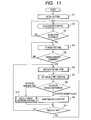
- Step S1 Initial setting is executed in Step S1, and an electric power generation control routine is executed in Step S2.
- the field control executed through the use of the synchronous rectification control, the battery voltage, the command battery voltage and the temperature detected by the temperature sensor circuit.
- Step S3 it is judged whether idling stop, that is, the engine 120 stops, or not, and if judgment is not the idling stop, processing is advanced to Step S2, and the electric power generation continues. If the judgment is the idling stop, a standby state setting for restarting the engine 120 is executed in Step S4.
- the standby state setting there is an operation where a predetermined field current is allowed to pass through the field winding 8 in advance so that a torque occurs immediately at the time of restart.
- the predetermined field current varies according to the electric constant of the field winding 8 or the amount of torque necessary to restart the engine 120.
- the standby state setting can be dealt with by changing a variable of the memory.
- Step S5 it is judged whether there is a restart command of the engine 120, or not.
- the standby state continues, and when there is the restart command, the processing is advanced to Step S6.
- Step S6 the motor drive routine is executed.
- the rotational speed of the motor-alternator 100 is detected in Step S7, and the detected rotational speed is compared with a targeted rotational speed Nref. In the case where the detected rotational speed is equal to or less than the targeted rotational speed Nref, a set value of the field current is maintained in Step S9.
- Step S10 a field magnetic current reduction routine is executed in Step S10, and the field magnetic current is reduced down to a predetermined value. Then, it is judged whether the engine 120 is restarted, or not, in Step S11.
- the restart judgment in Step S11 is made by, for example, a command signal from the engine control device 140.
- the processing is advanced to the electric power generation control in Step S2, and when the engine 120 does not start, the processing is returned to Step S6, and the motor drive routine continues. If the engine 120 starts at a high rotational speed while the field current is kept large, and a large electric power is rapidly generated, a rapid load fluctuation of the engine 120 occurs.
- Step S10 is a routine that is executed to reduce the field current and to prevent from such a rapid load fluctuation of the engine.
- this embodiment desirably applies not a system of bringing the switching semiconductor device into operation at a carrier frequency of several kHz as the PWM control system, but a system of driving the motor with one on/off operation per one cycle as the motor drive system.
- a serge voltage dependent on a wiring inductance of causing a change in turn off speed of a current and a current value is applied to the switching semiconductor device.
- the serge voltage there is a method of reducing the wiring inductance by disposing the electrolyte capacitor with the capacity of about 0.5 mF to 10 mF between the battery and the ground.
- a turn off speed of the current is made gentle.
- the loss in the switching semiconductor element which occurs every time switching is conducted cannot be ignored.
- the amount of loss caused by switching per unit time can be reduced.
- the system of driving the motor by bringing the switching semiconductor device in operation with one on/off per one cycle can be performed by the following control: controlling the gate voltage output of the switching semiconductor device in synchronism with the a hole sensor output that switches to high and low every 180° according to an angle between the rotor windings and the stator windings of the respective phases as shown in Fig. 3.
- the hole sensor can also serve as the rotation sensor 73.
- the hole sensor outputs H_U1, H_V1, and H_W1 shown in Fig. 13 have a relationship different in the phase by 120° with respect to the respective outputs.
- a gate signal U1g1 becomes a gate off voltage due to the rising of the hole sensor output H_U1.
- the gate voltage is controlled so as to generate the gate on-state voltage of the switching semiconductor device of the upper arm of the same phase after a delay time.
- the delay time is provided because the switching semiconductor devices of the upper and lower arms are prevented from turning on at the same time.
- an inverter circuit can be constituted by provision of only a capacitor with a small capacity of about 1 ⁇ F which filters the noises from a direct current cable.
- the above-mentioned motor-alternator 100 according to this embodiment has the following advantages.
- the integration of the rotating electric machine body 1 with the inverter device 50 can be realized by substantially the same size as that of the normal vehicle alternator while the costs are suppressed.
- the present invention provides the motor-alternator 100 having the inverter compatible with existing alternators, as a part necessary for realizing the idling stop system.
- the present invention is made to realize the idling stop system that is substantially identical with the existing vehicle layout, but when the present invention is considered as the system, it is necessary to combine the system with a lead battery that allows a large current output in a short period of time. For example, a current output from the battery 150 at the time of restarting the engine is about tenth of several seconds, and becomes 200 to 400 amperes of the same degree as that in the case where the engine starts due to the stator.
- 2004-133693 has a performance that can hold the battery voltage to 10 V or higher at the time of outputting a large current in a short period of time with a volume that is equal to or less than that of the conventional lead battery.
- the combination of the winding lead battery with the motor-alternator of the present invention can provide an idling stop system that is substantially identical with the existing vehicle layout.
- the idling stop system can be realized without remarkably changing the layout within the engine room.
Landscapes
- Engineering & Computer Science (AREA)
- Chemical & Material Sciences (AREA)
- Combustion & Propulsion (AREA)
- Mechanical Engineering (AREA)
- Transportation (AREA)
- General Engineering & Computer Science (AREA)
- Power Engineering (AREA)
- Control Of Eletrric Generators (AREA)
- Inverter Devices (AREA)
- Electric Propulsion And Braking For Vehicles (AREA)
Abstract
Description
Claims (11)
- Vehicle rotating electric machine mounted on a vehicle and electrically connected to a vehicle power supply, the electric machine comprising:wherein the power converting device (50) comprises:a rotating electric machine body (1); anda power converting device (50) mounted on the rotating electric machine body (1),wherein the power control circuit (55) is configured by connecting a plurality of the following series circuits in parallel, each of the series circuits includes a P-channel MOS semiconductor device disposed at a higher potential side and an N-channel MOS semiconductor device disposed at a lower potential side which are electrically connected in series, anda module unit (52) having a power control circuit (55), anda control unit (51) that controls the operation of the power control circuit (55),
the power control circuit (55) controls a power that is supplied from a vehicle power supply or a power that is supplied to the vehicle power supply,
the control unit (51) comprises:a control circuit (53) that outputs command signals for driving the P-channel MOS semiconductor devices and the N-channel MOS semiconductor devices, respectively; anda driver circuit (54) that outputs drive signals for driving the P-channel MOS semiconductor devices and the N-channel MOS semiconductor devices to those MOS semiconductor devices respectively upon receiving the command signals outputted from the control circuit (53). - Vehicle rotating electric machine according to claim 1, wherein the control circuit (53) and the driver circuit (54) are comprised of a plurality of electric circuit elements, respectively, and
the plurality of electric circuit elements are integrated and mounted on a substrate, and mounted on the rotating electric machine body (1). - Vehicle rotating electric machine according to claim 1 or 2, wherein the driver circuit (54) operates to output the drive signals for driving the P-channel MOS semiconductor devices and the N-channel MOS semiconductor devices, respectively, to the P-channel MOS semiconductor devices and the N-channel MOS semiconductor devices, respectively, with the power that is supplied from the vehicle power supply as a power supply.
- The vehicle rotating electric machine according to at least one of the claims 1 to 3, wherein the rotating electric machine is mounted on an automobile (200) which stops the internal combustion during stop of the automobile (200) and restarts the internal combustion with the driving force of the rotating electric machine at the time of starting the automobile (200), and uses a vehicle electrical power supply for the rotating electric machine;
the rotating electric machine body (1) mechanically connected to the internal combustion engine (120); and
the control circuit (53) is comprised of a plurality of electric circuit elements, its power source is a power supply where the power from the vehicle power supply is stepped down, and operates to output the command signals for driving the P-channel MOS semiconductor devices and the N-channel MOS semiconductor devices;
the driver circuit (54) is comprised of a plurality of electric circuit elements, its power source is the vehicle power supply, and operates to output the drive signals for driving the P-channel MOS semiconductor devices and the N-channel MOS semiconductor devices to those MOS semiconductor devices respectively;
the plurality of electric circuit elements are integrated and mounted on a substrate, and mounted on the rotating electric machine body (1). - The vehicle rotating electric machine according to at least one of the claims 1 to 4,
wherein the P-channel MOS semiconductor devices and the N-channel MOS semiconductor devices are field effect transistors,
wherein each pair of the P-channel MOS semiconductor device and the N-channel MOS semiconductor device have a drain electrode thereof connected to conductors of the same potential, and are mounted on the conductors, and
wherein the conductors are mounted on the rotating electric machine body (1) in an electrically insulated state. - The vehicle rotating electric machine according to at least one of the claims 1 to 5,
wherein the control unit (51) comprises means for starting the rotating electric machine as an electric motor, and decreasing a field current that is supplied to a field winding (8) of the rotating electric machine when the rotation speed of the rotating electric machine is equal to or more than a predetermined rotation speed. - The vehicle rotating electric machine according to at least one of the claims 1 to 6, wherein the control unit (51) includes memory means (53m, 53n) rewritable stored information,
the memory means (53m, 53n) stores the predetermined rotation speed and a reduction ratio of the field current, and
the predetermined rotation speed and the reduction ratio of the field current can be changed by rewriting the stored information of the memory means (53m, 53n). - The vehicle rotating electric machine according to at least one of the claims 1 to 7,
wherein the control unit (51) comprises means for adjusting the operation speeds of the P-channel MOS semiconductor devices and the N-channel MOS semiconductor devices, and a memory device that stores information for setting the operation speed therein, and
wherein the operation speed adjusting means adjusts the operation speeds of the P-channel MOS semiconductor devices and the N-channel MOS semiconductor devices according to the operation speed information from the memory device. - The vehicle rotating electric machine according to at least one of the claims 1 to 8, wherein the conductor has one temperature sensing element for sensing the temperatures of the P-channel MOS field effect transistors and the N-channel MOS field effect transistors.
- The vehicle rotating electric machine according to at least one of the claims 1 to 9,
wherein the control unit (51) is comprised of at least one chip in which a plurality of electronic circuit elements of constituting the control circuit (53) and the driver circuit (54) are integrated,
the chip is electrically connected to the conductor and mounted on the conductor, and
the conductor is mounted on an electrically conductive radiation member disposed on the rotating electric machine body (1) in an electrically insulated state. - The vehicle rotating electric machine according to at least one of the claims 1 to 10, wherein a winding lead battery (150) is used for the vehicle power supply.
Applications Claiming Priority (4)
| Application Number | Priority Date | Filing Date | Title |
|---|---|---|---|
| JP2004117027 | 2004-04-12 | ||
| JP2004117027 | 2004-04-12 | ||
| JP2005033760A JP2005328690A (en) | 2004-04-12 | 2005-02-10 | Rotating electric machine for vehicles |
| JP2005033760 | 2005-02-10 |
Publications (2)
| Publication Number | Publication Date |
|---|---|
| EP1589632A2 true EP1589632A2 (en) | 2005-10-26 |
| EP1589632A3 EP1589632A3 (en) | 2006-10-18 |
Family
ID=34935020
Family Applications (1)
| Application Number | Title | Priority Date | Filing Date |
|---|---|---|---|
| EP05007951A Withdrawn EP1589632A3 (en) | 2004-04-12 | 2005-04-12 | Integrated inverter unit for a motor-generator |
Country Status (3)
| Country | Link |
|---|---|
| US (2) | US7208918B2 (en) |
| EP (1) | EP1589632A3 (en) |
| JP (1) | JP2005328690A (en) |
Cited By (3)
| Publication number | Priority date | Publication date | Assignee | Title |
|---|---|---|---|---|
| GB2463652A (en) * | 2008-09-18 | 2010-03-24 | Controlled Power Technologies | An integrated starter generator device incorporating the control and power electronics |
| WO2011121195A1 (en) * | 2010-03-30 | 2011-10-06 | Valeo Equipements Electriques Moteur | Method of controlling the function of restarting an automatic start/stop system for a vehicle combustion engine, and corresponding system |
| CN110637383A (en) * | 2018-01-30 | 2019-12-31 | 株式会社Lg化学 | Series-parallel converter and battery module having the same |
Families Citing this family (33)
| Publication number | Priority date | Publication date | Assignee | Title |
|---|---|---|---|---|
| JP4121475B2 (en) * | 2004-03-30 | 2008-07-23 | 三菱電機株式会社 | Power generation control device for vehicle generator |
| JP2005328690A (en) * | 2004-04-12 | 2005-11-24 | Hitachi Ltd | Rotating electric machine for vehicles |
| JP4275614B2 (en) * | 2004-12-10 | 2009-06-10 | 三菱電機株式会社 | Rotating electric machine for vehicles |
| JP4286773B2 (en) * | 2004-12-27 | 2009-07-01 | 三菱電機株式会社 | Motor generator equipment |
| JP2007012857A (en) * | 2005-06-30 | 2007-01-18 | Renesas Technology Corp | Semiconductor device |
| JP4402057B2 (en) * | 2006-02-21 | 2010-01-20 | 三菱電機株式会社 | Controller-integrated rotating electrical machine |
| US7609016B2 (en) * | 2006-02-23 | 2009-10-27 | Infineon Technologies Ag | Systems and methods for driving a motor |
| JP4248565B2 (en) * | 2006-06-13 | 2009-04-02 | トヨタ自動車株式会社 | Vehicle drive mechanism |
| EP2677134B1 (en) | 2006-11-15 | 2016-03-23 | Mitsubishi Electric Corporation | Automotive hybrid engine assist system |
| JP4274267B2 (en) * | 2007-05-08 | 2009-06-03 | トヨタ自動車株式会社 | Vehicle start control device |
| DE102007035570A1 (en) * | 2007-07-26 | 2009-02-05 | Universität Kassel | Double-fed asynchronous generator and method of operation |
| KR101505551B1 (en) * | 2007-11-30 | 2015-03-25 | 페어차일드코리아반도체 주식회사 | Semiconductor power module package with temperature sensor mounted thereon and method of fabricating the same |
| JP2010004598A (en) * | 2008-06-18 | 2010-01-07 | Mitsubishi Electric Corp | Controller integrated dynamo-electric machine |
| JP4628460B2 (en) * | 2008-10-22 | 2011-02-09 | 三菱電機株式会社 | Rotating electric machine and manufacturing method thereof |
| US20100195286A1 (en) * | 2009-02-02 | 2010-08-05 | Rakesh Kumar Dhawan | Heat sink mechanism for internally integrated inverter hub (i3h) motor for light electric vehicles |
| JP5353422B2 (en) * | 2009-05-08 | 2013-11-27 | 株式会社デンソー | Vehicle power generation control device |
| JP4907694B2 (en) | 2009-05-13 | 2012-04-04 | 三菱電機株式会社 | Rotating electric machine |
| US7782015B1 (en) * | 2009-07-30 | 2010-08-24 | Billy Joe Aaron | Electric power system |
| ITTO20110924A1 (en) * | 2011-10-14 | 2013-04-15 | Merlo Project S R L Con Unico Socio | ELECTRO-HYDRAULIC HYBRID WORKING MACHINE |
| JP5855128B2 (en) | 2011-12-15 | 2016-02-09 | 三菱電機株式会社 | Power converter and control method of power converter |
| JP5955435B1 (en) * | 2015-04-16 | 2016-07-20 | 三菱電機株式会社 | Belt-driven controller integrated AC motor generator |
| JP6493004B2 (en) * | 2015-06-17 | 2019-04-03 | 株式会社デンソー | Controller-integrated rotating electrical machine |
| JP6524929B2 (en) * | 2016-01-27 | 2019-06-05 | 株式会社デンソー | Power converter |
| JP6733288B2 (en) * | 2016-04-27 | 2020-07-29 | いすゞ自動車株式会社 | Hybrid vehicle |
| JP6563378B2 (en) * | 2016-11-04 | 2019-08-21 | 株式会社東芝 | Automatic voltage regulator, automatic voltage regulation method, automatic voltage regulation program, generator excitation system and power generation system |
| JP6755845B2 (en) * | 2017-09-26 | 2020-09-16 | 株式会社東芝 | Motor drive system |
| WO2019075571A1 (en) * | 2017-10-19 | 2019-04-25 | Kinova Inc. | Instrument drive mechanism for robotics |
| JP7055659B2 (en) * | 2018-02-15 | 2022-04-18 | 東芝テック株式会社 | Liquid circulation device and liquid discharge device |
| DE112018007338T5 (en) * | 2018-03-23 | 2020-12-10 | Mitsubishi Electric Corporation | Electric lathe with brush |
| DE102020210555A1 (en) * | 2020-08-20 | 2022-02-24 | Robert Bosch Gesellschaft mit beschränkter Haftung | Device and method for saving analog inputs on a control unit |
| FR3118341A1 (en) * | 2020-12-18 | 2022-06-24 | Valeo Equipements Electriques Moteur | Assembly comprising an electrical machine, an inverter and an interconnector |
| CN113595464B (en) * | 2021-07-20 | 2023-12-19 | 中车大连电力牵引研发中心有限公司 | An internal combustion electric transmission tractor transmission system control device and control method |
| CN117507785B (en) * | 2022-07-29 | 2024-12-10 | 比亚迪股份有限公司 | Drive assembly and vehicle having the same |
Family Cites Families (24)
| Publication number | Priority date | Publication date | Assignee | Title |
|---|---|---|---|---|
| KR910008548B1 (en) * | 1987-05-07 | 1991-10-18 | 가부시키가이샤 히타치세이사쿠쇼 | Voltage regulator of charging generator |
| US5132604A (en) * | 1989-04-04 | 1992-07-21 | Honda Giken Kogyo Kabushiki Kaisha | Engine starter and electric generator system |
| JPH02266854A (en) * | 1989-04-04 | 1990-10-31 | Honda Motor Co Ltd | Engine starting/generator |
| US5093611A (en) * | 1989-07-20 | 1992-03-03 | Honda Giken Kogyo Kabushiki Kaisha | Output circuit for portable generators |
| JP3370119B2 (en) | 1993-01-20 | 2003-01-27 | 株式会社日立製作所 | Control device for vehicle charging generator |
| JP3329402B2 (en) | 1993-09-07 | 2002-09-30 | 株式会社日立製作所 | Control method and control device for vehicle charging generator |
| JP3374491B2 (en) * | 1993-12-24 | 2003-02-04 | 株式会社デンソー | Electric generator for vehicle |
| US6049108A (en) * | 1995-06-02 | 2000-04-11 | Siliconix Incorporated | Trench-gated MOSFET with bidirectional voltage clamping |
| JP3606026B2 (en) | 1997-11-18 | 2005-01-05 | 株式会社デンソー | Vehicle charging device |
| US6239996B1 (en) * | 2000-01-24 | 2001-05-29 | Massachusetts Institute Of Technology | Dual output alternator system |
| US6465996B2 (en) * | 2000-03-08 | 2002-10-15 | Denso Corporation | Constant voltage circuit with a substitute circuit in case of input voltage lowering |
| JP2001310720A (en) * | 2000-04-28 | 2001-11-06 | Denso Corp | Load drive circuit |
| EP1170847B1 (en) * | 2000-06-22 | 2010-08-04 | Denso Corporation | Rotary electric machine for vehicle |
| JP2002089417A (en) | 2000-09-13 | 2002-03-27 | Unisia Jecs Corp | Engine starter |
| JP3618081B2 (en) * | 2000-11-29 | 2005-02-09 | 株式会社日立製作所 | Rectifying device for charging generator for vehicles |
| JP4290346B2 (en) * | 2001-02-01 | 2009-07-01 | 本田技研工業株式会社 | Car charging system |
| JP3950653B2 (en) | 2001-08-29 | 2007-08-01 | 株式会社日立製作所 | Driving method of MOS rectifier |
| JP2003217647A (en) * | 2002-01-21 | 2003-07-31 | Japan Storage Battery Co Ltd | Wound lead-acid battery |
| DE10211463B3 (en) | 2002-03-15 | 2004-01-08 | Daimlerchrysler Ag | Motor vehicle and method for automatically switching off and starting an internal combustion engine |
| FR2842042A1 (en) * | 2002-07-04 | 2004-01-09 | Valeo Equip Electr Moteur | CONTROL AND POWER MODULE OF AN INTEGRATED ALTERNOMETER |
| JP4003611B2 (en) * | 2002-10-28 | 2007-11-07 | トヨタ自動車株式会社 | Generator motor |
| JP4007212B2 (en) * | 2003-03-07 | 2007-11-14 | トヨタ自動車株式会社 | Generator motor |
| JP4147987B2 (en) | 2003-03-17 | 2008-09-10 | 株式会社日立製作所 | Multi-phase AC rotating electric machine |
| JP2005328690A (en) * | 2004-04-12 | 2005-11-24 | Hitachi Ltd | Rotating electric machine for vehicles |
-
2005
- 2005-02-10 JP JP2005033760A patent/JP2005328690A/en active Pending
- 2005-04-11 US US11/102,627 patent/US7208918B2/en not_active Expired - Lifetime
- 2005-04-12 EP EP05007951A patent/EP1589632A3/en not_active Withdrawn
-
2007
- 2007-04-16 US US11/735,819 patent/US20070182384A1/en not_active Abandoned
Cited By (6)
| Publication number | Priority date | Publication date | Assignee | Title |
|---|---|---|---|---|
| GB2463652A (en) * | 2008-09-18 | 2010-03-24 | Controlled Power Technologies | An integrated starter generator device incorporating the control and power electronics |
| GB2463652B (en) * | 2008-09-18 | 2011-08-10 | Controlled Power Technologies Ltd | Electrical machine |
| WO2011121195A1 (en) * | 2010-03-30 | 2011-10-06 | Valeo Equipements Electriques Moteur | Method of controlling the function of restarting an automatic start/stop system for a vehicle combustion engine, and corresponding system |
| FR2958339A1 (en) * | 2010-03-30 | 2011-10-07 | Valeo Equip Electr Moteur | METHOD FOR CONTROLLING THE RESTART FUNCTION OF A SYSTEM FOR AUTOMATIC STARTING / STOPPING OF A THERMAL MOTOR OF A VEHICLE, AND CORRESPONDING SYSTEM |
| CN110637383A (en) * | 2018-01-30 | 2019-12-31 | 株式会社Lg化学 | Series-parallel converter and battery module having the same |
| CN110637383B (en) * | 2018-01-30 | 2022-03-15 | 株式会社Lg化学 | Series-parallel converter and battery module having the same |
Also Published As
| Publication number | Publication date |
|---|---|
| JP2005328690A (en) | 2005-11-24 |
| US7208918B2 (en) | 2007-04-24 |
| US20050237033A1 (en) | 2005-10-27 |
| US20070182384A1 (en) | 2007-08-09 |
| EP1589632A3 (en) | 2006-10-18 |
Similar Documents
| Publication | Publication Date | Title |
|---|---|---|
| US7208918B2 (en) | Vehicle rotating electric machine | |
| US7759831B2 (en) | Switching device, generator-motor apparatus using switching device, drive system including generator-motor apparatus, and computer-readable recording medium on which a program for directing computer to perform control of generator-motor apparatus is recorded | |
| US7471004B2 (en) | Driving/electric-power generating system for vehicle | |
| US7610973B2 (en) | Automotive electric motor-generator apparatus | |
| JP4359250B2 (en) | Interface circuit, power converter, and in-vehicle electric system | |
| US7589481B2 (en) | Control device integrated dynamo-electric machine | |
| US7362001B2 (en) | Generator-motor | |
| JP2000324857A (en) | Multi-type power supply device, equipment and motor drive device equipped with this power supply device, and hybrid vehicle | |
| US7411324B2 (en) | Generator-motor | |
| JP4007212B2 (en) | Generator motor | |
| US7541758B2 (en) | MOS rectifying device, driving method thereof, and motor generator and motor vehicle using thereof | |
| JP4003611B2 (en) | Generator motor | |
| JP4221999B2 (en) | Generator motor | |
| JP2004147363A (en) | Control device for AC motor generator for vehicles | |
| JP2004208487A (en) | Generator motor |
Legal Events
| Date | Code | Title | Description |
|---|---|---|---|
| PUAI | Public reference made under article 153(3) epc to a published international application that has entered the european phase |
Free format text: ORIGINAL CODE: 0009012 |
|
| AK | Designated contracting states |
Kind code of ref document: A2 Designated state(s): AT BE BG CH CY CZ DE DK EE ES FI FR GB GR HU IE IS IT LI LT LU MC NL PL PT RO SE SI SK TR |
|
| AX | Request for extension of the european patent |
Extension state: AL BA HR LV MK YU |
|
| PUAL | Search report despatched |
Free format text: ORIGINAL CODE: 0009013 |
|
| AK | Designated contracting states |
Kind code of ref document: A3 Designated state(s): AT BE BG CH CY CZ DE DK EE ES FI FR GB GR HU IE IS IT LI LT LU MC NL PL PT RO SE SI SK TR |
|
| AX | Request for extension of the european patent |
Extension state: AL BA HR LV MK YU |
|
| RIC1 | Information provided on ipc code assigned before grant |
Ipc: H01L 29/00 20060101ALI20060914BHEP Ipc: F02N 11/08 20060101ALI20060914BHEP Ipc: H02J 7/14 20060101AFI20050601BHEP |
|
| 17P | Request for examination filed |
Effective date: 20070418 |
|
| AKX | Designation fees paid |
Designated state(s): DE FR IT |
|
| STAA | Information on the status of an ep patent application or granted ep patent |
Free format text: STATUS: THE APPLICATION IS DEEMED TO BE WITHDRAWN |
|
| 18D | Application deemed to be withdrawn |
Effective date: 20081101 |