BACKGROUND OF THE INVENTION
1. Field of the Invention
The present invention relates to a gaming machine in which a game is
conducted by using symbols variably displayed and thereafter stopped.
2. Description of Related Art
In conventional gaming machines, for example, a slot machine, a plurality of
reels are rotated for a predetermined time and coins are paid out corresponding to a
symbol combination which is displayed when all reels are stopped. And in a case that
slot machines are roughly classified based on kinds of reels, there exist a mechanical
type of slot machine in which plural reels on each outer periphery of which symbols are
formed are rotatably provided and a video slot machine in which a plurality of
hypothetical reels (graphics of reels), which are displayed on a display device, are
rotated.
And in the video slot machine, since there is no mechanical restriction against
the symbols formed on each of the reels, it can be informed to a player that a game
state becomes a winning state, in which coins are paid out, by changing display mode
of the symbols, for example, by automatic pseudo rotation of the symbols around a
horizontal axis line under a state that the reels are stopped. For example, see
Japanese Unexamined publication No. 7-313659.
However, in the above video slot machine, a chance to change the display mode
of the symbols is limited to a time when the game pays out awards, therefore the
chance to appeal to the player by changing the display mode of the symbols is limited.
SUMMARY OF THE INVENTION
Taking the above situation into consideration, the present invention has been
done and has an object to provide a gaming machine in which a display mode of
symbols stopped and displayed can be changed based on an operation by a player,
thereby familiarity of the player for games can be increased.
In order to accomplish the above object, according to one aspect of the present
invention, it is provided a gaming machine having a display device for variably
displaying and stopping symbols thereon and a game controller for conducting a
payout corresponding to a symbol combination stopped and displayed on the display
device,
the gaming machine comprising:
According to the present invention, the display mode of the symbol stopped and
displayed on the display device is changed by the symbol movement device, thereby the
display mode of the symbol stopped and displayed on the display device can be changed
by player's operation. Therefore, familiarity of the player for a game can be
increased.
The above and further objects and novel features of the invention will more
fully appear from the following detailed description when the same is read in
connection with the accompanying drawings. It is to be expressly understood,
however, that the drawings are for purpose of illustration only and not intended as a
definition of the limits of the invention.
BRIEF DESCRIPTION OF THE DRAWINGS
The accompanying drawings, which are incorporated in and constitute a part of
this specification illustrate embodiments of the invention and, together with the
description, serve to explain the objects, advantages and principles of the invention.
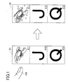
Fig. 1 is an explanatory view showing a state that symbols are variably changed
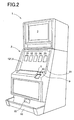
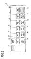
when a player touches to a symbol stopped and displayed through a touch panel, Fig. 2 is a perspective view of a slot machine, Fig. 3 is a front view of a control panel, Fig. 4 is a block diagram of a control system in the slot machine, Fig. 5 is a block diagram schematically showing a liquid crystal drive circuit for
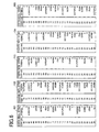
a lower liquid crystal display, Fig. 6 is an explanatory view schematically showing symbol rows each of which
is variably displayed on a variable display portion in a base game, Fig. 7 is an explanatory view showing one of symbols which constructs a part of
the symbol row, Fig. 8 is an explanatory view showing winning combinations and payouts
corresponding thereto, Fig. 9 is an explanatory view showing a lottery table for the symbols which are
stopped and displayed, Fig. 10 is an explanatory view showing stop areas of five variable display
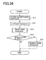
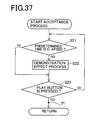
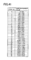
portions, Fig. 11 is an explanatory view showing the first pay line, Fig. 12 is an explanatory view showing the second pay line, Fig. 13 is an explanatory view showing the third pay line, Fig. 14 is an explanatory view showing the fourth pay line, Fig. 15 is an explanatory view showing the fifth pay line, Fig. 16 is an explanatory view showing the sixth pay line, Fig. 17 is an explanatory view showing the seventh pay line, Fig. 18 is an explanatory view showing the eighth pay line, Fig. 19 is an explanatory view showing the ninth pay line, Fig. 20 is an explanatory view showing the tenth pay line, Fig. 21 is an explanatory view showing the eleventh pay line, Fig. 22 is an explanatory view showing the twelfth pay line, Fig. 23 is an explanatory view showing the thirteenth pay line, Fig. 24 is an explanatory view showing the fourteenth pay line, Fig. 25 is an explanatory view showing the fifteenth pay line, Fig. 26 is an explanatory view showing the sixteenth pay line, Fig. 27 is an explanatory view showing the seventeenth pay line, Fig. 28 is an explanatory view showing the eighteenth pay line, Fig. 29 is an explanatory view showing the nineteenth pay line, Fig. 30 is an explanatory view showing the twentieth pay line, Fig. 31 is an explanatory view showing the twenty-first pay line, Fig. 32 is an explanatory view showing the twenty-second pay line, Fig. 33 is an explanatory view showing the twenty-third pay line, Fig. 34 is an explanatory view showing the twenty-fourth pay line, Fig. 35 is an explanatory view showing the twenty-fifth pay line, Fig. 36 is a flowchart of a main process program, Fig. 37 is a flowchart of a start acceptance process program, Fig. 38 is a flowchart of a lottery process program, Fig. 39 is a flowchart of a base game process program, Fig. 40 is a flowchart of a free game process program, Fig. 41 is an explanatory view showing a lottery table for the symbols which are
stopped and displayed, Fig. 42 is an explanatory view showing a state that one of the symbols
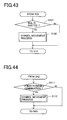
constructing a part of the symbol row is variably changed and displayed, Fig. 43 is a flowchart of a start acceptance process program, Fig. 44 is a flowchart of a base game process program, Fig. 45 is a flowchart of a program for variably changing the symbols, Fig. 46 is an explanatory view schematically showing the symbol
rows each of which is variably changed and displayed on the variable display portion
in the bonus game, and Fig. 47 is a flowchart of a base game process program executed in another
embodiment.
DETAILED DESCRIPTION OF THE PREFERRED EMBODIMENTS
Hereinafter, concerning with a gaming machine according to the present
invention, an embodiment embodying the present invention in a slot machine will be
described in detail with reference to the drawings. First, an outline construction of
the slot machine will be described with reference to Figs. 2 to 4. Fig. 2 is a
perspective view of the slot machine. Fig. 3 is a front view of a control panel. Fig 4
is a block diagram schematically showing a control system of the slot machine.
In Fig. 2, the slot machine 1 has a cabinet 2 which forms whole construction of
the slot machine 1. At an upper position of a front plane of the cabinet 2, an upper
liquid crystal display 3 is arranged and a lower liquid crystal display 4 is arranged on
a device front panel 20 which is arranged at a center position of the front plane of the
cabinet 2. Here, both the upper liquid crystal display 3 and the lower liquid crystal
display 4 are constructed from liquid crystal display generally used. On the upper
liquid crystal display 3, it is indicated information concerning with a game such as
methods, kinds of winning combinations and payouts corresponding thereto and
various effects. And on a surface of the lower liquid crystal display 4, a touch panel
121 is arranged. Further, on the lower liquid crystal display 4, credits are displayed
and five variable display portions 21, 22, 23, 24 and 25 are basically displayed as
shown in Fig. 2. On each of the variable display portion 21, 22, 23, 24 and 25, various
symbols are variably displayed while being scrolled from an upper direction toward a
lower direction, thereafter stopped and displayed.
Therefore, in the slot machine 1 of the embodiment, a slot game (there exist a
base game and a bonus game) is conducted through a video reels which are realized by
displaying variable display portions 21 to 25 on the lower liquid crystal display 4. In
the slot game (there exist a base game and a bonus game), there exist three symbols
stopped and displayed on each of the variable display portions 21 to 25. That is to say,
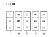
as shown in Fig. 10, the variable display portions 21 to 25 are divided into first stop
areas 211, 221, 231, 241, 251, second stop areas 212, 222, 232, 242, 252, and third stop
areas 213, 223, 233, 243, 253. And the symbols are respectively stopped and
displayed on the stop areas 211 - 213, 221 - 223, 231 - 233, 241 - 243, 251 - 253.
And in this slot game (base game and bonus game), there exist twenty-five pay
lines, each spanning five stop areas among the stop areas 211 - 213, 221 - 223, 231 -
233, 241 - 243, 251 - 253. If each of the pay lines is activated and specific symbols
are aligned with a specific display mode along the activated pay line when the symbols
are stopped and displayed, a predetermined payout is given to the player. Here, each
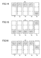
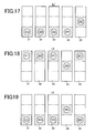
of the pay lines will be concretely described with reference to Figs. 11 to 35. In Figs
11 to 35, one pay line is indicated by shaded portions.
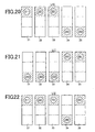
That is to say, as shown in Fig. 11 by shaded portions, the first pay line L1 is
formed from the second stop areas 212, 222, 232, 242, 252.
And as shown in Fig. 12 by shaded portions, the second pay line L2 is formed
from the first stop areas 211, 221, 231, 241, 251.
And as shown in Fig. 13 by shaded portions, the third pay line L3 is formed
from the third stop areas 213, 223, 233, 243, 253.
And as shown in Fig. 14 by shaded portions, the fourth pay line L4 is formed
from the first stop areas 211, 221, 231, 241 and the third stop area 253.
And as shown in Fig. 15 by shaded portions, the fifth pay line L5 is formed from
the first stop area 251 and the third stop areas 213, 223, 233, 243.
And as shown in Fig. 16 by shaded portions, the sixth pay line L6 is formed
from the first stop areas 211, 221, 231, 241 and the second stop area 252.
And as shown in Fig, 17 by shaded portions, the seventh pay line L7 is formed
from the second stop area 252 and the third stop areas 213, 223, 233, 243.
And as shown in Fig. 18 by shaded portions, the eighth pay line L8 is formed
from the first stop areas 211, 221, 231, 251 and the second stop area 242.
And as shown in Fig. 19 by shaded portions, the ninth pay line L9 is formed
from the second stop area 242 and the third stop areas 213,223, 233, 253.
And as shown in Fig. 20 by shaded portions, the tenth pay line L10 is formed
from the first stop areas 211, 221, 231 and the third stop areas 243, 253.
And as shown in Fig. 21 by shaded portions, the eleventh pay line L11 is formed
from the first stop areas 241, 251 and the third stop areas 213, 223, 233.
And as shown in Fig. 22 by shaded portions, the twelfth pay line L12 is formed
from the first stop areas 211, 221, 231, 151 and the third stop area 243.
And as shown in Fig. 23 by shaded portions, the thirteenth pay line L13 is
formed from the first stop area 241 and the third stop areas 213, 223, 233, 253.
And as shown in Fig. 24 by shaded portions, the fourteenth pay line L14 is
formed from the first stop areas 241, 251 and the second stop areas 212, 222, 232.
And as shown in Fig. 25 by shaded portions, the fifteenth pay line L15 is formed
from the second stop areas 212, 222, 232 and the third stop areas 243, 253.
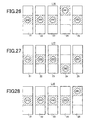
And as shown in Fig. 26 by shaded portions, the sixteenth pay line L16 is
formed from the first stop area 241 and the second stop areas 212, 222, 232, 252.
And as shown in Fig. 27 by shaded portions, the seventeenth pay line L17 is
formed from the second stop areas 212, 222, 232, 252 and the third stop area 243.
And as shown in Fig. 28 by shaded portions, the eighteenth pay line L18 is
formed from the first stop area 251 and the second stop areas 212, 222, 232, 242.
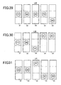
And as shown in Fig. 29 by shaded portions, the nineteenth pay line L19 is
formed from the second stop areas 212, 222, 232, 242 and the third stop area 253.
And as shown in Fig. 30 by shaded portions, the twentieth pay line L20 is
formed from the first stop areas 241, 251 and the second stop areas 212, 222 and the
third stop area 233.
And as shown in Fig. 31 by shaded portions, the twenty-first pay line L21 is
formed from the first stop area 231 and the second stop areas 212, 222 and the third
stop areas 243, 253.
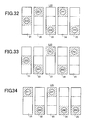
And as shown in Fig. 32 by shaded portions, the twenty-second pay line L22 is
formed from the first stop areas 221, 241 and the second stop area 212 and the third
stop areas 233, 253.
And as shown in Fig. 33 by shaded portions, the twenty-third pay line L23 is
formed from the first stop areas 231, 251 and the second stop area 212 and the third
stop areas 223, 243.
And as shown in Fig. 34 by shaded portions, the twenty-fourth pay line L24 is
formed from the first stop areas 211, 231 and the third stop areas 223, 243, 253.
And as shown in Fig. 35 by shaded portions, the twenty-fifth pay line L25 is
formed from the first stop areas 221, 241, 251 and the third stop areas 213, 233.
Here, the pay line (s) activated among the 25 pay lines is/are called as
"activated pay line (s)"
Back to Fig. 2, at an lower position of the lower liquid crystal display 4, a
control panel 5 which is projected forward is formed. In the control panel 5 as shown
in Fig. 3, a COLLECT button 31 and a GAME RULES button 32 are arranged in an
upper step from the most left side, and a BET 1 PER LINE button 33, a BET 2 PER
LINE button 34, a BET 3 PER LINE button 35, a BET 5 PER LINE button 36, a BET 8
PER LINE button 37 and a WIN START FEATURE button 38 are arranged in a
middle step from the most left side. Further, a RED PLAY 1 LINE button 39, a PLAY
2 LINES button 40, a PLAY 5 LINES button 41, a PLAY 20 LINES button 42, a
BLACK PLAY 25 LINES button 43 and a GAMBLE RESERVE button 44 are arranged
in a lower step from the most left side. And as shown in Fig. 2, at the right side of the
control panel 5, a coin insertion slot 9 and a bill insertion portion 10 are provided.
Here, the COLLECT button 31 is a button which is pressed when the base game
is terminated, and when the COLLECT button 31 is pressed, coins equal to the credits
obtained in the game are paid out from a coin payout opening 15 to a coin tray 16. To
the COLLECT button 31, a COLLECT switch 45 is attached and a switch signal is
output to a CPU 50 from the COLLECT switch 45 on the basis of press of the
COLLECT button 31 (see Fig. 4).
The GAME RULES button 32 is a button which is pressed if operation methods
of the game cannot be understood, and when the GAME RULES button 32 is pressed,
various help information is displayed on the upper liquid crystal display 3 or the lower
liquid crystal display 4. To the GAME RULES button 32, a GAME RULES switch 46
is attached and a switch signal is output to the CPU 50 from the GAME RULES switch
46 on the basis of press of the GAME RULES button 32 (see Fig. 4).
To the coin insertion slot 9, a coin sensor 49 is arranged and when a coin is
inserted in the coin insertion slot 9, a coin detection signal is output to the CPU 50
through the coin sensor 49 (see Fig. 4) and credit corresponding to the inserted coin is
added. And to the bill insertion portion 10, a bill sensor 67 is arranged and when a
bill is inserted in the bill insertion portion 10, a bill detection signal is output to the
CPU 50 through the bill sensor 67 (see Fig. 4), and credit corresponding to the inserted
bill is added.
The BET 1 PER LINE button 33 is a button to bet one credit to each of the
activated pay lines every one press thereof. To this BET 1 PER LINE button 33, a
1-BET switch 57 is attached and when the BET 1 PER LINE button 33 is pressed, a
switch signal is output to the CPU 50 from the 1-BET switch 57 (see Fig. 4). The
BET 2 PER LINE button 34 is a button to start the game with 2 bets against each of
the activated pay lines on the basis of press thereof. To the BET 2 PER LINE button
34, a 2-BET switch 58 is attached and when the BET 2 PER LINE button 34 is pressed,
a switch signal is output to the CPU 50 from the 2-BET switch 58 (see Fig. 4).
The BET 3 PER LINE button 35 is a button to start the game wit 3 bets against
each of the activated pay lines on the basis of press thereof. To the BET 3 PER LINE
button 35, a 3-BET switch 59 is attached and when the BET 3 PER LINE button 35 is
pressed, a switch signal is output to the CPU 50 from the 3-BET switch 59 (see Fig. 4).
And the BET 5 PER LINE button 36 is a button to start the game with 5 bets against
each of the activated pay lines on the basis of press thereof. To the BET 5 PER LINE
button 36, a 5-BET switch 60 is attached and when the BET 5 PER LINE button 36 is
pressed, a switch signal is output to the CPU from the 5-BET switch 60 (see Fig. 4).
The BET 8 PER LINE button 37 is a button to start the game with 8 bets
against each of the activated pay lines on the basis of press thereof. To the BET 8
PER LINE button 37, a 8-BET switch 61 is attached and when the BET 8 PER LINE
switch 37 is pressed, a switch signal is output to the CPU 50 from the 8-BET switch 61
(see Fig. 4).
Therefore, there will exist 1 bet, 2 bets, 3 bets, 5 bets and 8 bets as the bet
number which can be betted by press of the BET 1 PER LINE button 33, the BET 2
PER LINE button 34, the BET 3 PER LINE button 35, the BET 5 PER LINE button 36
and the BET 8 PER LINE button 37.
The WIN START FEATURE button 38 is a button to start a bonus game or add
the payout obtained in the bonus game to the credit on the basis of press thereof. To
the WIN START FEATURE button 38, a WIN·START switch 47 is attached and when
the WIN START FEATURE button 38 is pressed, a switch signal is output to the CPU
50 from the WIN·START switch 47 (see Fig. 4).
The RED PLAY 1 LINE button 39 is a button to start the game while retaining
the number of the activated pay line to "1" on the basis of press thereof. To the RED
PLAY 1 LINE button 39, a 1-LINE switch 62 is attached and when the RED PLAY 1
LINE button 39 is pressed, a switch signal is output to the CPU 50 from the 1-LINE
switch 62 (see Fig. 4). And the PLAY 2 LINES button 40 is a button to start the game
while retaining the number of the activated pay line to "2" on the basis of press thereof.
To the PLAY 2 LINES button 49, a 2-LINES switch 63 is attached and when the PLAY
2 LINES button 40 is pressed, a switch signal is output to the CPU 50 from the 2-LINES
switch 63 (see Fig. 4).
The PLAY 5 LINES button 41 is a button to start the game while retaining the
number of the activated pay line to "5" on the basis of press thereof. To the PLAY 5
LINES button 41, a 5-LINES switch 64 is attached and when the PLAY 5 LINES
button 41 is pressed, a switch signal is output to the CPU 50 from the 5-LINES switch
64 (see Fig. 4). And the PLAY 20 LINES button 42 is a button to start the game while
retaining the number of the activated pay lien to "20" on the basis of press thereof.
To the PLAY 20 LINES button 42, a 20-LINES switch 65 is attached and when the
PLAY 20 LINES button 42 is pressed, a switch signal is output to the CPU 50 from the
20-LINES switch 65 (see Fig. 4).
The BLACK PLAY 25 LINES button 43 is a button to start the game while
retaining the number of the activated pay line to "25" on the basis of press thereof.
To the BLACK PLAY 25 LINES button 43, a 25-LINES switch 66 is attached and when
the BLACK PLAY 25 LINES button 43 is pressed, a switch signal is output to the CPU
50 from the 25-LINES switch 66 (see Fig. 4).
Therefore, there will exist "1" pay line, "2" pay lines, "5" pay lines, "20" pay lines
and "25" pay lines as the number of the activated pay lines which can be determined
by press of the RED PLAY 1 LINE button 39, the PLAY 2 LINES button 49, the PLAY
5 LINES button 41, the PLAY 20 LINES button 42, the BLACK PLAY 25 LINES
button 43.
Here, when the RED PLAY 1 LINE button 39 is pressed, the pay line L1 shown
in Fig. 11 is activated. And when the PLAY 2 LINES button 40 is pressed, the pay
lines L1, L2 shown in Figs. 11 and 12 are activated. And when the PLAY 5 LINES
button 41 is pressed, the pay lines L1 ~ L5 shown in Figs. 11 to 15 are activated. And
when the PLAY 20 LINES button 42 is pressed, the pay lines L1 ~ L20 shown in Figs.
11 to 30 are activated. And when the BLACK PLAY 25 LINES button 43 is pressed,
the pay lines L1 ~ L25 shown in Figs. 11 to 35 are activated.
And each of the RED PLAY 1 LINE button 39, the PLAY 2 LINES button 49,
the PLAY 5 LINES button 41, the PLAY 20 LINES button 42 and the BLACK PLAY 25
LINES button 43 is a button to start the game with the present bet number and the
number of the activated pay lines and to start variable display of the symbols on each
of the variable display portions 21 to 25 in the lower liquid crystal display 4.
Here, the RED PLAY 1 LINE button 39 and the BLACK PLAY 25 LINES
button 43 are also used for selecting red or black in the double down game which is
conducted by using the credit obtained in the bonus game.
The GAMBLE RESERVE button 44 is a button to be pressed when the player
leaves the seat and to shift to the double down game after the bonus game is
terminated. To the GAMBLE RESERVE button 44, a GAMBLE ·RESERVE switch
48 is attached and when the GAMBLE RESERVE button 44 is pressed, a switch signal
is output to the CPU 50 from the GAMBLE · RESERVE switch 48 (see Fig. 4).
And at a lower position of the cabinet 2, a coin payout opening 15 is formed and
a coin tray 16 for receiving coins paid out from the coin payout opening 15 is provided.
Within the coin payout opening 15 it is arranged a coin detection portion 73
(mentioned later) which is constructed from sensors and the like (see Fig. 4). And the
coin detection portion 73 counts the number of coins paid out from the coin payout
opening 15.
Next, with reference to Fig. 6, it will be described the symbol rows which are
variable displayed while being scrolled on each of the variable display portions 21 to 25,
the symbol rows being displayed on the lower liquid crystal display 4 in the base game.
In Fig. 6, the symbol row indicated by a first reel strip 101 corresponds to a symbol row
variably displayed on the variable display portion 21, the symbol row indicated by a
second reel strip 102 corresponds to a symbol row variably displayed on the display
portion 22, the symbol row indicated by a third reel strip 103 corresponds to a symbol
row variably displayed on the variable display portion 23, the symbol row indicated by
a fourth reel strip 104 corresponds to a symbol row variably displayed on the variable
display portion 24 and the symbol row indicated by a fifth reel strip 105 corresponds to
a symbol row variably displayed on the variable display portion 25.
Here, the symbol rows respectively indicated by the first to fifth reel strips 101
to 105 have different symbol rows from each other and each symbol row is constructed
from 12 symbols by voluntarily combining "LOBSTER", "SHARK", "FISH", "PUNK",
"OCTOPUS", "CRAB", "WORM", "A", "K", "Q", "J" and "SARDINE".
Here, "LOBSTER" shows the symbol of lobster as shown in Fig. 7. And
although "SHARK", "FISH", "PUNK", "OCTOPUS", "CRAB", "WORM", "SARDINE"
are not shown, each symbol shows a shark, a fish, a punk, an octopus, a crab, a worm
and a sardine, respectively. And "A", "K", "Q" and "J" shows a symbol of English
character, respectively.
Further, "SARDINE" is a scatter symbol to shift to the bonus game as
mentioned later and in a case that more than three "SARDINE" symbols are totally
displayed on the variable display portions 21 to 25, the game state can be shifted to the
bonus game.
Here, in a case that the symbol rows indicated by the first to fifth reel strips
101 to 105 are scrolled on the variable display portions 21 to 25 and thereafter stopped
and displayed, three symbols are stopped and displayed in each variable display
portion, as mentioned in the above.
And various winning symbol combinations are preset based on plural kinds of
symbol combinations and when the symbol combination corresponding to the winning
symbol combination is stopped on the activated pay line, the payout is added to the
credit corresponding to the winning symbol combination. This point is as same as
that in the convention slot machine, thus explanation thereof will be omitted.
Next, it will be described a construction of control system in the slot machine 1
with reference to Fig. 4. Fig. 4 is a block diagram schematically showing a control
system of the slot machine 1.
In Fig. 4, the control system of the slot machine 1 is basically constructed from
a CPU 50, and a ROM 51 and a RAM 52 are connected to the CPU 50. In the ROM 51,
a main process program mentioned later, a base game process program, a bonus game
process program, a lottery table used when it is conducted lottery to determine the
symbols which are stopped and displayed in the base game, a lottery table used when
it is conducted lottery to determine the symbols which are stopped and displayed in the
bonus game, and the other various programs necessary for control of the slot machine
1 and data tables. And the RAM 52 is a memory to temporarily store various data
calculated by the CPU 50.
And to the CPU 50, a clock pulse generator 53 for generating standard clock
pulses and a frequency divider 54 are connected, and a random number generator 55
for generating random numbers and a random number sampling circuit 56 are also
connected. The random number sampled through the random number sampling
circuit 56 is utilized in various lotteries of the winning symbol combinations and the
like. Further, to the CPU 50, the COLLECT switch 45 attached to the COLLECT
button 31, the GAME·RULES switch 46 attached to the GAME RULES button 32, the
1-BET switch 57 attached to the BET 1 PER LINE button 33, the 2-BET switch 58
attached to the BET 2 PER LINES button 34, the 3-BET switch 59 attached to the
BET 3 PER LINES button 35, the 5-BET switch 60 attached to the BET 5 PER LINES
button 36, the 8-BET switch 60 attached to the BET 8 PER LINES button 37, the
WIN-START switch 47 attached to the WIN START FEATURE button 38, the 1-LINE
switch 62 attached to the RED PLAY 1 LINE button 39, the 2-LINES switch 63
attached to the PLAY 2 LINES button 40, the 5-LINES switch 64 attached to the PLAY
5 LINES button 41, the 20-LINES switch 65 attached to the PLAY 20 LINES button 42,
the 25-LINES switch 66 attached to the BLACK PLAY 25 LINES button 43 and the
GAMBLE · RESERVE switch 48 attached to the GAMBLE RESERVE button 44 are
connected, respectively. The CPU 50 conducts control to execute various operations
each of which corresponds to each button, based on the switch signal output from each
switch by press thereof.
Further, to the CPU 50, the coin sensor 49 arranged in the coin insertion slot 9
and the bill sensor 67 arranged in the bill insertion portion 10 are respectively
connected. The coin sensor 49 detects coins inserted from the coin insertion slot 9
and the CPU 50 calculates the number of inserted coins based on the coin detection
signal output from the coin sensor 49. The bill sensor 67 detects kinds and sum of the
bill inserted from the bill insertion portion 10 and the CPU 50 calculates the credit
number equal to the sum of bill, based on the bill detection signal output from the bill
sensor 67.
To the CPU 50, a hopper 71 is connected through a hopper drive circuit 70.
When a drive signal is output to the hopper drive circuit 70 from the CPU 50, the
hopper 71 pays out a predetermined number of coins from the coin payout opening 15.
And to the CPU 50, a coin detection portion 73 is connected through a payout
completion signal circuit 72. The coin detection portion 73 is arranged in the coin
payout opening 15 and when the coin detection portion 73 detects that a
predetermined number of coins are paid out from the coin payout opening 15, a coin
payout detection signal is output to the payout completion signal circuit 72 from the
coin detection portion 73, thereby the payout completion signal circuit 72 outputs a
payout completion signal to the CPU 50. Further, to the CPU 50, the upper liquid
crystal display 3 and the lower liquid crystal display 4 are connected through a liquid
crystal drive circuit 74, and the upper liquid crystal display 3 and the lower liquid
crystal display 4 are controlled by the CPU 50.
Here, as shown in Fig. 5, the liquid crystal drive circuit 74 is constructed from a
program ROM 81, an image ROM 82, an image control CPU 83, a work RAM 84, a
VDP (video display processor) 85 and a video RAM 68. And in the program ROM 81,
there are stored an image control program for controlling display of the upper liquid
crystal display 3 and the lower liquid crystal display 4 and various selection tables.
And in the image ROM 82, for example, there are stored dot data for forming images of
the symbol rows indicated by the first to fifth reel strips 101 to 105 in Fig. 6, such
images being displayed on the lower liquid crystal display 4 (or variable display
portions 21 to 25). And the image control CPU 83 determines the images displayed
on the upper liquid crystal display 3 and the lower liquid crystal display 4 among the
dot data stored beforehand in the image ROM 82, according to the image control
program stored beforehand in the program ROM 81 based on parameters set by the
CPU 50. Further, the work RAM 84 functions as temporary memory when the image
control program is executed by the image control CPU 83. And the VDP 85 forms
images corresponding to display contents determined by the image control CPU 83 and
outputs such images to the upper liquid crystal display 3 and the lower liquid crystal
display 4. Thereby, for example, the symbol rows indicated by the first to fifth reel
strips 101 to 105 are scrolled and displayed on the lower liquid crystal display 4 (or the
variable display portions 21 to 25). Here, the video RAM 86 functions as temporary
memory when images are formed by the VDP 85.
And to the CPU 50, LEDs 78 are connected through a LED drive circuit 77.
Many LEDs 78 are arranged on the front plane of the slot machine 1 and are controlled
so as to turn on or turn off by the LED drive circuit 77 based on the drive signal from
the CPU 50, when various effects are done. Further, a sound output circuit 79 and a
speaker 80 are connected to the CPU 50 and the speaker 80 produces various effect
sounds when various effects are conducted based on the output signal from the sound
output circuit 79.
To the CPU 50, a touch panel 121 is connected through a touch panel drive
circuit 122. The touch panel 121 is arranged on the image plane of the lower liquid
crystal display 4 and when the player touches on the variable display portions 21 to 25
by the finger, the touch panel 121 can recognize through the touch panel drive circuit
122 not only the variable display portion on which the player touches among the
variable display portions 21 to 25 but also the stop area on which the player touches
among the first stop areas 211, 221, 231, 241, 151, the second stop areas 212, 222, 232,
242, 252 and the third stop areas 213, 223, 233, 243, 253.
That is to say, the touch panel 121 can recognize through the touch panel drive
circuit 122 the variable display portion on which the player touches among the
variable display portions 21 to 25, based on coordinate information of the portion
which is touched by the player.
Here, it will be described with reference to Fig. 9 the lottery table which is used
when the symbols stopped and displayed on the activated pay line L1 shown in Fig. 11
are determined, when the base game is conducted by using five variable display
portions 21 to 25 in the slot machine 1.
The symbols stopped and displayed on the activated pay line L1 shown in Fig.
11 are determined every each of the variable display portions 21 to 25. In order to
realize this, code Nos. "00" ~ "29" are respectively allotted to the symbol in each symbol
row indicated by the first to fifth reel strips 101 to 105 as shown in Fig. 6, in order of
the upper most symbol. And the lottery table shown in Fig. 9 is provided beforehand.
Further, five random numbers are sampled by the random number sampling circuit 56
so as to correspond to each of the variable display portions 21 to 25.
Hereinafter, the symbol row indicated by the first reel strip 101 in Fig. 6 will be
described. The symbols in the symbol row are scrolled on the variable display portion
21. At that time, if the random number sampled by the random number sampling
circuit 56 is "0", the symbol "J" (English character) allotted to the code No. "00" is
stopped and displayed on the activated pay line L1 shown in Fig. 11, if the random
number is "1", the symbol "Q" (English character) allotted to the code No "01" is
stopped and displayed on the activated pay line L1, if the random number is "2", the
symbol "LOBSTER" (lobster shown in Fig. 7) allotted to the code No. "02" is stopped
and displayed on the activated pay line L1 shown in Fig. 11, if the random number is
"3", the symbol "J" (English character) allotted to the code No. "03" is stopped and
displayed on the activated pay line L1 shown in Fig. 11, if the random number is "4",
the symbol "Q" (English character) allotted to the code No. "04" is stopped and
displayed on the activated pay line L1 shown in Fig. 11, if the random number is "5",
the symbol "CRAB" allotted to the code No. "05" is stopped and displayed on the
activated pay line L1 shown in Fig. 11, if the random number is "6", the symbol "A"
(English character) allotted to the code No. "06" is stopped and displayed on the
activated pay line L1 shown in Fig. 11, if the random number is "7", the symbol
"WORM" allotted to the code No. "07" is stopped and displayed on the activated pay
line L1 shown in Fig. 11, if the random number is "8", the symbol "K" (English
character) allotted to the code No. "08" is stopped and displayed on the activated pay
line L1 shown in Fig. 11, if the random number is "9", the symbol "FISH" allotted to
the code No. "09" is stopped and displayed on the activated pay line L1 shown in Fig.
11, and if the random number is "10", the symbol "PUNK" allotted to the code No. "10"
is stopped and displayed on the activated pay line L1 shown in Fig. 11.
And if the random number is "11", the symbol "Q" (English character) allotted
to the code No. "11" is stopped and displayed on the activated pay line L1 shown in Fig.
11, if the random number is "12", the symbol "SHARK" allotted to the code No. "12" is
stopped and displayed on the activated pay line L1 shown in Fig. 11, if the random
number is "13", the symbol "CRAB" allotted to the code No. "13" is stopped and
displayed on the activated pay line L1 shown in Fig. 11, if the random number is "14",
the symbol "K" (English character) allotted to the code No. "14" is stopped and
displayed on the activated pay line L1 shown in Fig. 11, if the random number is "15",
the symbol "A" (English character) allotted to the code No. "15" is stopped and
displayed on the activated pay line L1 shown in Fig. 11, if the random number is "16",
the symbol "OCTOPUS" allotted to the code No. "16" is stopped and displayed on the
activated pay line L1 shown in Fig. 11, if the random number is "17", the symbol "J"
(English character) allotted to the code No. "17" is stopped and displayed on the
activated pay line L1 shown in Fig. 11, if the random number is "18", the symbol "Q"
(English character) allotted to the code No. "18" is stopped and displayed on the
activated pay line L1 shown in Fig. 11, and if the random number is "19", the symbol
"FISH" allotted to the code No. "19" is stopped and displayed on the activated pay line
L1 shown in Fig. 11.
And if the random number is "20", the symbol "K" (English character) allotted
to the code No. "20" is stopped and displayed on the activated pay line L1 shown in Fig.
11, if the random number is "21", the symbol "J" (English character) allotted to the
code No. "21" is stopped and displayed on the activated pay line L1 shown in Fig. 11, if
the random number is "22", the symbol "SARDINE" allotted to the code No. "22" is
stopped and displayed on the activated pay line L1 shown in Fig. 11, if the random
number is "23", the symbol "CRAB" allotted to the code No. "23" is stopped and
displayed on the activated pay line L1 shown in Fig. 11, if the random number is "24",
the symbol "J" (English character) allotted to the code No. "24" is stopped and
displayed on the activated pay line L1 shown in Fig. 11, if the random number is "25",
the symbol "WORM" allotted to the code No. "25" is stopped and displayed on the
activated pay line L1 shown in Fig. 11, if the random number is "26", the symbol "Q"
(English character) allotted to the code No. "26" is stopped and displayed on the
activated pay line L1 shown in Fig. 11, if the random number is "27", the symbol
"CRAB" allotted to the code No. "27" is stopped and displayed on the activated pay line
L1 shown in Fig. 11, if the random number is "28", the symbol "A" (English character)
allotted to the code No. "28" is stopped and displayed on the activated pay line L1
shown in Fig. 11, and if the random number is "29", the symbol "FISH" allotted to the
code No. "29" is stopped and displayed on the activated pay line L1 shown in Fig. 11.
Here, as for the symbol row indicated by the second reel strip 102 in Fig. 6 the
symbols of which are scrolled on the variable display portion 22, the symbol row
indicated by the third reel strip 103 in Fig. 6 the symbols of which are scrolled on the
variable display portion 23, the symbol row indicated by the fourth reel strip 104 in Fig.
6 the symbols of which are scrolled on the variable display portion 24 and the symbol
row indicated by the fifth reel strip 105 in Fig. 6 the symbols of which are scrolled on
the variable display portion 25, the above control is similarly conducted.
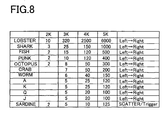
Next, with reference to Fig. 8, it will be described the winning symbol
combinations and payouts thereof in a case that the base game is done by using five
variable display portions 21 to 25 in the slot machine 1. Fig. 8 is an explanatory view
showing the winning symbol combinations and payouts thereof in a case that the base
game is done by using five variable display portions 21 to 25, and shows payouts in a
case that the bet number is "1". Therefore, if the bet number is "1", the payout
number shown in Fig. 8 is added to the credit, and if the bet number is more than "2",
the value obtained by multiplying the bet number with the payout number shown in
Fig. 8 is added to the credit.
Here, concretely describing the winning symbol combinations and payouts
thereof in the base game, as shown in Fig. 8, if the symbols "LOBSTER" (shown in Fig.
7) are stopped and displayed in series along the activated pay line on the variable
display portions 21 and 22 (if two symbols "LOBSTER" appear in series from the left
end (this case is called as "2K")), the payout number "10" can be obtained. And if the
symbols "LOBSTER" are stopped and displayed in series along the activated pay line
on the variable display portions 21 to 23 (if three symbols "LOBSTER" appear in series
from the left end (this case is called as "3K")), the payout number "320" can be
obtained. Further, if the symbols "LOBSTER" are stopped and displayed in series
along the activated pay line on the variable display portions 21 to 24 (if four symbols
"LOBSTER" appear in series from the left end (this case is called as "4K")), the payout
number "2500" can be obtained. And if the symbols "LOBSTER" are stopped and
displayed in series along the activated pay line on the variable display portions 21 to
25 (if five symbols "LOBSTER" appear in series from the left end (this case is called as
"5K")), the payout number "6000" can be obtained.
And as for the symbol "SHARK", if the symbols "SHARK" are stopped and
displayed in series along the activated pay line on the variable display portions 21 and
22 (if two symbols "SHARK" appear in series from the left end (this case is called as
"2K")), the payout number "3" can be obtained. And if the symbols "SHARK" are
stopped and displayed in series along the activated pay line on the variable display
portions 21 to 23 (if three symbols "SHARK" appear in series from the left end (this
case is called as "3K")), the payout number "25" can be obtained. Further, if the
symbols "SHARK" are stopped and displayed in series along the activated pay line on
the variable display portions 21 to 24 (if four symbols "SHARK" appear in series from
the left end (this case is called as "4K")), the payout number "150" can be obtained.
And if the symbols "SHARK" are stopped and displayed in series along the activated
pay line on the variable display portions 21 to 25 (if five symbols "SHARK" appear in
series from the left end (this case is called as "5K")), the payout number "1000" can be
obtained.
And as for the symbol "FISH", if the symbols "FISH" are stopped and displayed
in series along the activated pay line on the variable display portions 21 and 22 (if two
symbols "FISH" appear in series from the left end (this case is called as "2K")), the
payout number "2" can be obtained. And if the symbols "FISH" are stopped and
displayed in series along the activated pay line on the variable display portions 21 to
23 (if three symbols "FISH" appear in series from the left end (this case is called as
"3K")), the payout number "15" can be obtained. Further, if the symbols "FISH" are
stopped and displayed in series along the activated pay line on the variable display
portions 21 to 24 (if four symbols "FISH" appear in series from the left end (this case is
called as "4K")), the payout number "120" can be obtained. And if the symbols "FISH"
are stopped and displayed in series along the activated pay line on the variable display
portions 21 to 25 (if five symbols "FISH" appear in series from the left end (this case is
called as "5K")), the payout number "500" can be obtained.
And as for the symbol "PUNK", if the symbols "PUNK" are stopped and
displayed in series along the activated pay line on the variable display portions 21 and
22 (if two symbols "PUNK" appear in series from the left end (this case is called as
"2K")), the payout number "2" can be obtained. And if the symbols "PUNK" are
stopped and displayed in series along the activated pay line on the variable display
portions 21 to 23 (if three symbols "PUNK" appear in series from the left end (this case
is called as "3K")), the payout number "10" can be obtained. Further, if the symbols
"PUNK" are stopped and displayed in series along the activated pay line on the
variable display portions 21 to 24 (if four symbols "PUNK" appear in series from the
left end (this case is called as "4K")), the payout number "120" can be obtained. And
if the symbols "PUNK" are stopped and displayed in series along the activated pay line
on the variable display portions 21 to 25 (if five symbols "PUNK" appear in series from
the left end (this case is called as "5K")), the payout number "400" can be obtained.
And as for the symbol "OCTOPUS", if the symbols "OCTOPUS" are stopped and
displayed in series along the activated pay line on the variable display portions 21 and
22 (if two symbols "OCTOPUS" appear in series from the left end (this case is called as
"2K")), the payout number "2" can be obtained. And if the symbols "OCTOPUS" are
stopped and displayed in series along the activated pay line on the variable display
portions 21 to 23 (if three symbols "OCTOPUS" appear in series from the left end (this
case is called as "3K")), the payout number "8" can be obtained. Further, if the
symbols "OCTOPUS" are stopped and displayed in series along the activated pay line
on the variable display portions 21 to 24 (if four symbols "OCTOPUS" appear in series
from the left end (this case is called as "4K")), the payout number "50" can be obtained.
And if the symbols "OCTOPUS" are stopped and displayed in series along the
activated pay line on the variable display portions 21 to 25 (if five symbols
"OCTOPUS" appear in series from the left end (this case is called as "5K")), the payout
number "300" can be obtained.
And as for the symbol "CRAB", if the symbols "CRAB" are stopped and
displayed in series along the activated pay line on the variable display portions 21 to
23 (if three symbols "CRAB" appear in series from the left end (this case is called as
"3K")), the payout number "7" can be obtained. Further, if the symbols "CRAB" are
stopped and displayed in series along the activated pay line on the variable display
portions 21 to 24 (if four symbols "CRAB" appear in series from the left end (this case
is called as "4K")), the payout number "50" can be obtained. And if the symbols
"CRAB" are stopped and displayed in series along the activated pay line on the
variable display portions 21 to 25 (if five symbols "CRAB" appear in series from the left
end (this case is called as "5K")), the payout number "200" can be obtained.
And as for the symbol "WORM", if the symbols "WORM" are stopped and
displayed in series along the activated pay line on the variable display portions 21 to
23 (if three symbols "WORM" appear in series from the left end (this case is called as
"3K")), the payout number "6" can be obtained. Further, if the symbols "WORM" are
stopped and displayed in series along the activated pay line on the variable display
portions 21 to 24 (if four symbols "WORM" appear in series from the left end (this case
is called as "4K")), the payout number "40" can be obtained. And if the symbols
"WORM" are stopped and displayed in series along the activated pay line on the
variable display portions 21 to 25 (if five symbols "WORM" appear in series from the
left end (this case is called as "5K")), the payout number "150" can be obtained.
And as for the symbol "A" (English character), if the symbols "A" are stopped
and displayed in series along the activated pay line on the variable display portions 21
to 23 (if three symbols "A" appear in series from the left end (this case is called as
"3K")), the payout number "5" can be obtained. Further, if the symbols "A" are
stopped and displayed in series along the activated pay line on the variable display
portions 21 to 24 (if four symbols "A" appear in series from the left end (this case is
called as "4K")), the payout number "25" can be obtained. And if the symbols "A" are
stopped and displayed in series along the activated pay line on the variable display
portions 21 to 25 (if five symbols "A" appear in series from the left end (this case is
called as "5K")), the payout number "120" can be obtained.
And as for the symbol "K" (English character), if the symbols "K" are stopped
and displayed in series along the activated pay line on the variable display portions 21
to 23 (if three symbols "K" appear in series from the left end (this case is called as
"3K")), the payout number "5" can be obtained. Further, if the symbols "K" are
stopped and displayed in series along the activated pay line on the variable display
portions 21 to 24 (if four symbols "K" appear in series from the left end (this case is
called as "4K")), the payout number "25" can be obtained. And if the symbols "K" are
stopped and displayed in series along the activated pay line on the variable display
portions 21 to 25 (if five symbols "K" appear in series from the left end (this case is
called as "5K")), the payout number "120" can be obtained.
And as for the symbol "Q" (English character), if the symbols "Q" are stopped
and displayed in series along the activated pay line on the variable display portions 21
to 23 (if three symbols "Q" appear in series from the left end (this case is called as
"3K")), the payout number "5" can be obtained. Further, if the symbols "Q" are
stopped and displayed in series along the activated pay line on the variable display
portions 21 to 24 (if four symbols "Q" appear in series from the left end (this case is
called as "4K")), the payout number "20" can be obtained. And if the symbols "Q" are
stopped and displayed in series along the activated pay line on the variable display
portions 21 to 25 (if five symbols "Q" appear in series from the left end (this case is
called as "5K")), the payout number "100" can be obtained.
And as for the symbol "J" (English character), if the symbols "J" are stopped
and displayed in series along the activated pay line on the variable display portions 21
to 23 (if three symbols "J" appear in series from the left end (this case is called as
"3K")), the payout number "5" can be obtained. Further, if the symbols "J" are
stopped and displayed in series along the activated pay line on the variable display
portions 21 to 24 (if four symbols "J" appear in series from the left end (this case is
called as "4K")), the payout number "20" can be obtained. And if the symbols "J" are
stopped and displayed in series along the activated pay line on the variable display
portions 21 to 25 (if five symbols "J" appear in series from the left end (this case is
called as "5K")), the payout number "100" can be obtained.
And in a case that the above payout is realized on plural activated pay lines, all
payouts are added to the credit.
On the other hand, as for the symbol "SARDINE", if two symbols "SARDINE"
appear (are stopped and displayed) on the variable display portions 21 to 25 with no
relation to the activated pay lines, that is, if the case "2K" is realized, the payout
number "2" can be obtained. If three symbols "SARDINE" appear (are stopped and
displayed) on the variable display portions 21 to 25 with no relation to the activated
pay lines, that is, if the case "3K" is realized, the payout number "5" can be obtained.
And if four symbols "SARDINE" appear (are stopped and displayed) on the variable
display portions 21 to 25 with no relation to the activated pay lines, that is, if the case
"4K" is realized, the payout number "10" can be obtained. Further, if five symbols
"SARDINE" appear (are stopped and displayed) on the variable display portions 21 to
25 with no relation to the activated pay lines, that is, if the case "5K" is realized, the
payout number "125" can be obtained.
Here, concerning with only the payout obtained by the symbol "SARDINE", the
payout number calculated by multiplying the payout number shown in Fig. 8 with the
total bet number (a product of the bet number and the number of activated pay line) is
added to the credit. At that time, if it exists the payout other than the payout on the
basis of the symbol "SARDINE", such payout is also added to the credit.
And as for the symbol "SARDINE", in a case that more than three symbols
"SARDINE" are totally stopped and displayed on the variable display portions 21 to 25
with no relation to the activated pay lines, not only the above payout can be obtained
but also the game state can be shifted to the bonus game.
Here, the bonus game is a game which is conducted after the base game is
terminated, and in many cases the bonus game is generally more beneficial for the
player. If the game state shifts to the bonus game, 15 - 25 games can be continuously
and automatically done without betting any credits corresponding to a result of the
lottery conducted when the game state shifts to the bonus game.
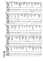
By the way, in the slot machine 1 according to the embodiment, when the bonus
game is conducted, the symbol row variably displayed while being scrolled on the
variable display portion 21 of the lower liquid crystal display 4 is the symbol row
indicated by the first reel strip 123 shown in Fig. 46, the symbol row variably
displayed while being scrolled on the variable display portion 22 of the lower liquid
crystal display 4 is the symbol row indicated by the second reel strip 124 shown in Fig.
46, the symbol row variably displayed while being scrolled on the variable display
portion 23 of the lower liquid crystal display 4 is the symbol row indicated by the third
reel strip 125 shown in Fig. 46, the symbol row variably displayed while being scrolled
on the variable display portion 24 of the lower liquid crystal display 4 is the symbol
row indicated by the fourth reel strip 126 shown in Fig. 46 and the symbol row
variably displayed while being scrolled on the variable display portion 25 of the lower
liquid crystal display 4 is the symbol row indicated by the fifth reel strip 127 shown in
Fig. 46.
Here, the symbol rows indicated by the reel strips 123 to 126 shown in Fig. 46
are as same as those indicated by the reel strips 101 to 104 shown in Fig. 6. On the
other hand, the symbol row indicated by the reel strip 127 shown in Fig. 46 is
substantially as same as the symbol row indicated by the reel strip 105 shown in Fig. 6,
except for the symbol "LOBSTER" (shown in Fig. 7) allotted to the code No. "10".
Here, as the bet number and the number of activated pay line in the bonus
game, the bet number and the number of activated pay line set in the base game are
utilized, respectively. And in the bonus game, although the winning symbol
combinations and payouts thereof in the bonus game are as same as those in the base
game, the symbol "SHARK" is handled as the symbol "LOBSTER" (shown in Fig. 7)
and if more than three symbols "SARDINE" totally appear (are totally stopped and
displayed), the game state in the bonus game can be again shifted to the bonus game.
Therefore, the player can obtain a lot of credits in many cases.
Next, the main process program done in the slot machine 1 will be described
with reference to Fig. 36. Fig. 36 is a flowchart of the main process program. In Fig.
36, at first, in step (abbreviated as "S" hereinafter) 11, a start acceptance process
shown in Fig. 37 is done. This process is a process for accepting the switch signal
output from the 1-BET switch 57, the 2-BET switch 58, the 3-BET switch 59, the 5-BET
switch 60, the 8-BET switch 61, the 1-LINE switch 62, the 2-LINES switch 63,
the 5-LINES switch 64, the 20-LIENS switch 65, the 25-LINES switch 66, based on
operation of the BET 1 PER LINE button 33, the BET 2 PER LINES button 34, the
BET 3 PER LINES button 35, the BET 5 PER LINES 36, the BET 8 PER LINES
button 37, the RED PLAY 1 LINE button 39, the PLAY 2 LINES button 40, the PLAY 5
LINES button 41, the PLAY 20 LINES button 42 or the BLACK PLAY 25 LINES
button 43. When the switch signal output from each switch is accepted, the game is
started.
And in S12, a lottery process shown in Fig. 16 mentioned later is done based on
the switch signal output from the 1-LINE switch 62, the 2-LINES switch 63, the 5-LINES
switch 64, the 20-LINES switch 65, the 25-LINES switch 66.
Here, if the bonus game is won, a repeat number of the bonus game is
determined. In this case, for example, such repeat number is selected among 10 - 25
games by a lottery.
Next, in S13, a base game process shown in Fig. 17 mentioned later is done.
Thereafter, procedure shifts to S14 and it is determined whether or not the bonus
game is won. Concretely, in the lottery process in S 12, if more than three symbols
"SARDINE" totally appear (are stopped and displayed) on the variable display portions
21 to 25 with no relation to the activated pay lines, the bonus game is won (S14: YES).
Thereby, procedure shifts to S15 and the main process program is terminated after the
bonus game process shown in Fig. 40 mentioned later is done. On the other hand, in
the lottery process of S12, if more than three symbols "SARDINE" does not totally
appear (are not stopped and displayed) on the variable display portions 21 to 25 with
no relation to the activated pay lines, the bonus game is not won (S14: NO), thereby
the main process program is terminated.
Next, the start acceptance process program conducted in the slot machine 1 will
be described with reference to Fig. 37. Fig. 37 is a flowchart of the start acceptance
process program. In S11 of the main process program shown in Fig. 36, the start
acceptance process is conducted. Here, to conduct this process, at first, procedure
shifts to S21 of Fig. 37 and it is determined whether or not a predetermined time (for
example, 15 seconds) is elapsed. Here, if it is determined that the predetermined
time is not elapsed (S21: NO), procedure shifts to S23, and on the other hand, if it is
determined that the predetermined time is elapsed (S21: YES), demonstration effect is
done on the upper liquid crystal display 3 or the lower liquid crystal display 4 in S22,
thereafter procedure shifts to S23. And in S23, it is determined whether or not
operation of the RED PLAY 1 LINE button 39, the PLAY 2 LINES button 40, the PLAY
5 LINES button 41, the PLAY 20 LINES button 42 or the BLACK PLAY 25 LINES
button 43 is done. Here, if it is determined that operation of the RED PLAY 1 LINE
button 39 and the like is not done (S23: NO), procedure returns to S21 and the above
procedures are repeated. On the other hand, if it is determined that operation of the
RED PLAY 1 LINE button 39 and the like is done (S23: YES), procedure returns to the
main process program of Fig. 36 and shifts to the lottery process in S12 even while the
demonstration effect is done.
Here, in the determination process in S23, such determination in S23 may be
conducted based on the other input signals other than the above operation signals.
Next, the lottery process program done in the slot machine 1 will be described
with reference to Fig. 38. Fig. 38 is a flowchart of the lottery process program. In
S12 of the main process program shown in Fig. 36, the lottery process is done. To
conduct this process, at first, procedure shifts to S31 of Fig. 38 and a symbol
determination process is conducted. Here, the symbols stopped and displayed on the
first pay line L1 in the base game are determined every each of the variable display
portions 21 to 25. Concretely, as mentioned above, five random number values are
sampled by the random number sampling circuit 56 so as to correspond to each of the
variable display portions 21 to 25 and the symbols stopped and displayed are
determined through the code Nos. based on the lottery table shown in Fig. 9. And if
the symbols stopped and displayed on the activated pay line are determined, a
determination process of the winning symbol combination is done in S32, thereafter
procedure returns to the main process program in Fig. 36 and shifts to the base game
process in S13. Here, concretely speaking, in the determination process of the
winning symbol combination, the winning symbol combination and the payout thereof
are determined based on the table shown in Fig. 8 through the code No. obtained in
S31, as mentioned.
Next, the base game process program done in the slot machine 1 will be
described with reference to Fig. 39. Fig. 39 is a flowchart of the base game process
program. In S13 of the main process program shown in Fig. 36, the base game is
conducted. To realized this, at first, in S41 of Fig. 39, scroll of each of the symbols is
done on the variable display portions 21 to 25 based on the switch signal output from
the 1-LINE switch 62, the 2-LINES switch 63, the 5-LINES switch 64, the 20-LINES
switch 65 or the 25-LINES switch 66, the switch signal being accepted in S11 of Fig.
36.
And in S42, scroll of each of the symbols on the variable display portions 21 to
25 is stopped.
Further, in S43, according to the symbol combination corresponding to the
winning symbol combination stopped and displayed on the variable display portions 21
to 25, the credit corresponding to the payout determined on the basis of the table
shown in Fig. 8 is paid out. Here, after process in S43 is done, procedure shifts to the
main process program shown in Fig. 36 and shifts to the determination process in S14.
Next, the bonus game process program done in the slot machine 1 will be
described with reference to Fig. 39. Fig. 39 is a flowchart of the bonus game process
program. In S14 of the main process program shown in Fig. 36, if it is determined
that the bonus game is won (S14: YES), procedure shifts to S15 of Fig. 36 and the
bonus game process is conducted. To realize this, at first, procedure shifts to S39
shown in Fig. 39 and the lottery process during the bonus game is done. Here, in the
bonus game, the symbols stopped and displayed on the first pay line L1 are determined
every each of the variable display portions 21 to 25. Concretely, as mentioned, five
random number values are sampled by the random number sampling circuit 56 so as
to correspond to each of the variable display portions 21 to 25, and the symbols stopped
and displayed are determined through the code Nos. based on the lottery table shown
in Fig. 9. And if the symbols stopped and displayed on the first pay line L1 are
determined, the winning symbol combination and the payout thereof are determined
based on the table shown in Fig. 8 through the code Nos.
Further, in the rotation process in S52, scroll of each of the symbols is
automatically done on the variable display portions 21 to 25.
And in the stop control process in S53, scroll of each of the symbols on the
variable display portions 21 to 25 is stopped.
Further, in the payout process in S54, according to the symbol combination
corresponding to the winning symbol combination stopped and displayed on the
variable display portions 21 to 25, the credit corresponding to the payout determined
based on the table in Fig. 8 (however, the symbol "SHARK" is handled as the symbol
"LOBSTER (shown in Fig. 7)) is paid out.
Next, procedure shifts to S55 and it is determined whether or not the execution
number of times of the bonus game reaches to the number of times determined in S12
of Fig. 36. At that time, if it is determined that the execution number of times of the
bonus game does not reach to the number of times already determined (S55: NO),
procedure returns to S51 and the above processes are repeated. On the other hand, if
it is determined that the execution number of times of the bonus game reaches to the
number of times already determined (S55: YES), the bonus game process program is
terminated.
Here, if the bonus game is won in S51, the repeat number of times of the bonus
game is determined again and the determined repeat number of times is added to the
"number of times determined in S12 of Fig. 36" used in the determination process in
S55. Thereby, when the bonus game is won during the bonus game, procedure can
again shift to the bonus game. Concretely speaking, for example, in a case that
procedure shifts to the bonus game with 20 number of times for the first time and the
bonus game with 17 number of times is won in the twelfth bonus game, the bonus
games are conducted in 25 times (20 times - 12 times + 17 times) thereafter.
And if the credit can be finally obtained in the bonus game, a double down game
to bet the credit is done after the bonus game is terminated. This double down game
will be omitted.
As mentioned in the above, the CPU 50 functions as "game controller" when the
main process program of Fig. 36 is executed.
By the way, in the slot machine 1 according to the embodiment, when the
symbols stopped and displayed on each of the variable display portions 21 to 25 are
touched and a predetermined condition is realized, the symbols touched can be moved
and effect sounds can be output. In order to realized this, for example, the process
shown in Fig. 43 is conducted at the time point W right after the determination process
of S23 in the start acceptance process program in Fig. 37 is done. That is to say, in
the start acceptance process program of Fig. 37, if it is determined that the play button
is pressed (S23: YES), procedure shifts to S101 in Fig. 43 and it is determined whether
or not a bill is inserted in S101. Concretely, this determination is done based on
whether or not the bill detection signal is output from the bill sensor 67. At that time,
if it is determined that the bill is not inserted (S101: NO), procedure returns to the
start acceptance process program in Fig. 37 and shifts to S12 of the main process
program in Fig. 36. On the other hand, it is determined that the bill is inserted
(S101: YES), procedure shifts to S102 and a symbol movement process mentioned later
is done, thereafter procedure returns to start acceptance process program in Fig. 37
and shifts to S12 of the main process program in Fig. 36.
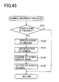
Here, the symbol movement process in S102 shown in Fig. 43 will be described
with reference to Fig. 45. Fig. 45 is a flowchart of the symbol movement process.
That is to say, as shown in Fig. 45, in the symbol movement process, at first, it is
determined whether or not the touch panel 121 is touched within the variable display
portions 21 to 25 in S121. At that time, if it is determined that the touch panel 121 is
not touched within the variable display portions 21 to 25 (S121: NO), procedure
returns to the process shown in Fig. 43. On the other hand, if it is determined that
the touch panel 121 is touched within the variable display portions 21 to 25 (S 121:
YES), procedure shifts to S122.
And in S122, the window touched by the finger is specified. Here, the window
is defined as any of the first stop areas 211, 221, 231, 241, 251, the second stop areas
212, 222, 232, 242, 252 and the third stop areas 213, 223, 233, 243, 253, within the
variable display portions 21 to 25. Further, when procedure shifts to S123, the
symbol stopped and displayed on the specified window is also specified.
And when procedure shifts to S124, the display mode of the symbol specified in
S123 is changed within the specified window. Concretely, for example, in a case that
the symbol specified in S123 is the symbol "LOBSTER" (shown in Fig. 7), the image
that the lobster springs as shown in Fig. 42 is displayed.
Further, when procedure shifts to S125, the effect sounds corresponding to
change of the display mode in S124 are output, thereafter procedure returns to the
process in Fig. 43. As for the concrete effect sounds, for example, if the symbol
specified in S123 is the symbol "LOBSTER" (shown in Fig. 7), the effect sounds such as
sprightly sounds representing springing lobster as shown in Fig. 42 are output.
Here, the images that the display mode of the symbol is changed are stored in
the image ROM 82, every each of the symbol "LOBSTER", the symbol "SHARK", the
symbol "FISH", the symbol "PUNK", the symbol "OCTOPUS", the symbol "CRAB", the
symbol "WORM", the symbol "SARDINE", the symbol "A", the symbol "K", the symbol
"Q" and the symbol "J". And the symbol specified in S123 is read out and output in
the window specified in S122. Further, the effect sounds when the display mode of
the symbol is changed are stored in the ROM 51, every each of the symbol "LOBSTER",
the symbol "SHARK", the symbol "FISH", the symbol "PUNK", the symbol
"OCTOPUS", the symbol "CRAB", the symbol "WORM", the symbol "SARDINE", the
symbol "A", the symbol "K", the symbol "Q" and the symbol "J". And the effect sounds
of the symbol specified in S123 are read out and output from the speaker 80.
As mentioned above, the CPU 50 functions as "first permission device" when
the process program in Fig. 43 is executed. And the CPU 50 functions as "symbol
movement device" when the symbol movement process program in Fig. 45 is executed.
Further, only when the symbol combination stopped and displayed on each of
the variable display portions 21 to 25 is the predetermined symbol combination, the
symbol can be moved and the effect sounds can be output based on that the symbol
stopped and displayed on each of the variable display portions 21 to 25 is touched by
the finger.
In order to realize the above, for example, the process shown in Fig. 44 is
conducted at the time point W2 right after the stop control process of S42 in the base
game process program in Fig. 39 is done. That is to say, in the base game process
program shown in Fig. 39, if the stop control process in S42 is executed, procedure
shifts to S111 in Fig. 44 and it is determined whether or not the symbol combination
stopped and displayed on each of the variable display portions 21 to 25 is the
predetermined symbol combination. At that time, if it is determined that the symbol
combination stopped and displayed on each of the variable display portions 21 to 25 is
not the predetermined symbol combination (S111: NO), procedure shifts to S43 of the
base game process program in Fig. 39. On the other hand, if the symbol combination
stopped and displayed on each of the variable display portions 21 to 25 is the
predetermined symbol combination (S111: YES), procedure shifts to S112 and the
symbol movement process in Fig. 45 already mentioned is conducted, thereafter
procedure shifts to S43 of the base game process program in Fig. 39.
As mentioned, when the program shown in Fig. 44 is executed, the CPU 50
functions as "second permission device".
Here, as for the predetermined symbol combinations in determination process
of S111, for example, it is conceivable a case that the symbol combination stopped and
displayed on each of the variable display portions 21 to 25 is the symbol combination
corresponding to the winning symbol combination shown in Fig. 8. At that time, the
object to be determined in S111 may be limited to the symbol combination stopped and
displayed on the pay line which is activated among the pay lines L1 ~ L25. In this
case, concerning with only the symbol combination corresponding to the winning
symbol combination shown in Fig. 8, the display mode thereof may be changed and the
effect sounds may be output.
As detailedly mentioned in the above, in the slot machine 1 according to the
embodiment, at the time that the game state shifts from one base game to another
base game, when a bill is inserted in the bill insertion portion 10 in a case that, for
example as shown in Fig. 1, the symbol "LOBSTER" is stopped and displayed on the
first stop area 211, the symbol "J" is stopped and displayed on the second stop area 212
and the symbol "Q" is stopped and displayed on the third stop area 213, within the
variable display portion 21, the symbol "LOBSTER" displayed on the first stop area
211 is displayed so as to spring and the effect sounds representing springing lobster
are output when the player touches on the first stop area 211 by the finger 128.
Therefore, since the display mode of the symbol "LOBSTER" is changed when the
player touches the symbol "LOBSTER" which is stopped and displayed, the player can
change the display mode of the symbol "LOBSTER" by player's operation. Thereby, it
can predict that meditation and attachment of the player against the symbol
"LOBSTER" increases, thus familiarity of the player for the video slot machine can be
increased. Accordingly, it is expected that repeaters who plays the video slot machine
can be obtained.
Here, the above point that the display mode of the symbol can be changed is not
limited to the first stop area 211 in the variable display portion 21 and can be realized
on the second stop area 212 or the third stop area 213 in the variable display portion
21. Further, similarly, the above point can be also realized on the first stop areas 221,
231, 241, 251, the second sop and display areas 222, 232, 242, 252 and the third atop
and display areas 223, 233, 243, 253.
And the above point is not limited to the symbol "LOBSTER" and can be
realized in each symbol of "SHARK", "FISH", "PUNK", "OCTOPUS", "CRAB",
"WORM" "SARDINE", "A", "K", "Q" and "J".
Further, the above point can be similarly realized in a case that the symbol
combination stopped and displayed on each of the variable display portions 21 to 25 is
the predetermined symbol combination (for example, the symbol combination
corresponding to the winning symbol combination shown in Fig. 8).
Here, the present invention is not limited to the above embodiment and various
changes and modifications can be done within the scope of the present invention.
For example, in the slot machine 1, when the player touches the symbol stopped
and displayed on each of the variable display portions 21 to 25 on a condition that a
bill is inserted in the bill insertion portion 10 (S101: YES), such symbol can be moved
and the effect sounds can be output (S124. S125). As for this point, it may be set the
condition that coins are inserted in the coin insertion slot 9 (the coin detection signal
from the coin sensor 49 is received). And it may be set the condition while the bonus
game process in Fig. 40 is executed or the start acceptance process in Fig. 37 is
executed. Further, without any condition, it is conceivable that the symbol stopped
and displayed on each of the variable display portions 21 to 25 can be always moved
and the effect sounds can be always output when the player touches such symbol by
the finger 128.
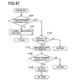
Further, at W2 of Fig. 39, the gaming machine of the present invention may run
the following processes shown in Fig. 47 alternatively to the steps described in Fig. 44.
In this embodiment, the symbol "LOBSTER" is used as a wild symbol.
Namely, as shown in Fig. 47, in the base game process program shown in Fig.
39, after the stop control process in S42 is executed, procedure shifts to S130 in Fig. 47
and it is determined whether or not the symbol combination stopped and displayed on
each of the variable display portions 21 to 25 is the predetermined symbol combination.
At that time, if it is determined that the symbol combination stopped and displayed on
each of the variable display portions 21 to 25 is the predetermined symbol combination
(S130: YES), procedure shifts to S131 and the symbol movement process in Fig. 45
already mentioned is conducted, thereafter procedure shifts to S43 of the base game
process program in Fig. 39. On the other hand, if it is determined that the symbol
combination stopped and displayed on each of the variable display portions 21 to 25 is
not the predetermined symbol combination (S130: NO), procedure shifts to S132 and
the gaming machine may request the player to drag the symbol "LOBSTER" onto a
desirable stop area, as shown in S132 of Fig. 47 so as to provide award. That is, it is
determined in S132 whether or not the symbol "LOBSTER" is dragged onto any one of
the stop areas. If it is determined that the symbol "LOBSTER" is not dragged (S132:
NO), procedure shifts to the main process program shown in Fig. 36. On the contrary,
if it is determined that the symbol "LOBSTER" is dragged onto any one of the stop
areas (S132: YES), the CPU 50 determines in S133 to which window the symbol
"LOBSTER" has been dragged on. Namely, the window to which the symbol
"LOBSTER" has been dragged on is specified in S133. Thereafter, the CPU 50
determines in S134 whether thus dragged symbol "LOBSTER" forms a predetermined
combination that results in award. That is, it is determined in S134 whether or not
the winning symbol combination is formed based on that the symbol "LOBSTER" is
dragged onto the stop area. If determined "NO" in S134, procedure shifts to the main
process program shown in Fig. 36. On the contrary, if determined "YES" in S134,
procedure shifts to S135, where the award is given to the player. That is, in S135,
according to the winning symbol combination, the coins are paid out. Thereafter,
procedure shifts to the main process program shown in Fig. 36.
The above mentioned dragging process may be combined with the symbol
movement process described in Fig. 44. Namely, after determined as "YES" in S111 of
Fig. 44, the gaming machine of the present invention may require the player to drag
the symbol "LOBSTER" to a desirable stop area so as to obtain additional awards.
Thereafter the CPU 50 may run the symbol movement process so that the player can
see that the symbol "LOBSTER" has resulted in the additional awards.
Although the embodiment above is described as a process in base game, the
dragging may be carried out in bonus game like free game.
And the present invention is not limited to the video slot machine, and for
example, when the player touches the symbol stopped and displayed on the lower
liquid crystal display 4 by the finger 128 in the game (for example, the poker game in
which trump symbols are used) that is executed by using symbols displayed on the
lower liquid crystal display 4, the symbol may be moved and the effect sounds may be
output.
Further, in the slot machine 1 of the embodiment, the symbol stopped and
displayed on the first pay line L1 is determined every each of the variable display
portions 21 to 25 in the base game and the bonus game, based on the lottery table in
Fig. 9 in which one random number value sampled through the random number
sampling circuit 56 and one code No. are corresponded with each other. As for this
point, for example, the symbol stopped and displayed on the first pay line L1 may be
determined every each of the variable display portions 21 to 25, based on the lottery
table in Fig. 41 in which a specific range of the random numbers sampled through the
random number sampling circuit 56 corresponds to one code No..
The present invention can be applied when the game is executed by using
symbols displayed on the display device.