EP1589487A2 - Gerät und Verfahren zur Rekonstruktion von dreidimensionalen Grafikdaten - Google Patents
Gerät und Verfahren zur Rekonstruktion von dreidimensionalen Grafikdaten Download PDFInfo
- Publication number
- EP1589487A2 EP1589487A2 EP05252360A EP05252360A EP1589487A2 EP 1589487 A2 EP1589487 A2 EP 1589487A2 EP 05252360 A EP05252360 A EP 05252360A EP 05252360 A EP05252360 A EP 05252360A EP 1589487 A2 EP1589487 A2 EP 1589487A2
- Authority
- EP
- European Patent Office
- Prior art keywords
- information
- graphics data
- geometric
- transparent
- unit
- Prior art date
- Legal status (The legal status is an assumption and is not a legal conclusion. Google has not performed a legal analysis and makes no representation as to the accuracy of the status listed.)
- Withdrawn
Links
Images





Classifications
-
- G—PHYSICS
- G09—EDUCATION; CRYPTOGRAPHY; DISPLAY; ADVERTISING; SEALS
- G09B—EDUCATIONAL OR DEMONSTRATION APPLIANCES; APPLIANCES FOR TEACHING, OR COMMUNICATING WITH, THE BLIND, DEAF OR MUTE; MODELS; PLANETARIA; GLOBES; MAPS; DIAGRAMS
- G09B19/00—Teaching not covered by other main groups of this subclass
- G09B19/0076—Body hygiene; Dressing; Knot tying
-
- G—PHYSICS
- G06—COMPUTING OR CALCULATING; COUNTING
- G06T—IMAGE DATA PROCESSING OR GENERATION, IN GENERAL
- G06T17/00—Three-dimensional [3D] modelling for computer graphics
-
- B—PERFORMING OPERATIONS; TRANSPORTING
- B42—BOOKBINDING; ALBUMS; FILES; SPECIAL PRINTED MATTER
- B42D—BOOKS; BOOK COVERS; LOOSE LEAVES; PRINTED MATTER CHARACTERISED BY IDENTIFICATION OR SECURITY FEATURES; PRINTED MATTER OF SPECIAL FORMAT OR STYLE NOT OTHERWISE PROVIDED FOR; DEVICES FOR USE THEREWITH AND NOT OTHERWISE PROVIDED FOR; MOVABLE-STRIP WRITING OR READING APPARATUS
- B42D5/00—Sheets united without binding to form pads or blocks
- B42D5/04—Calendar blocks
-
- G—PHYSICS
- G06—COMPUTING OR CALCULATING; COUNTING
- G06T—IMAGE DATA PROCESSING OR GENERATION, IN GENERAL
- G06T2210/00—Indexing scheme for image generation or computer graphics
- G06T2210/61—Scene description
Definitions
- the present invention relates to an apparatus for rendering 3D (three-dimensional) graphics data and more particularly to an apparatus and method for reconstructing 3D graphics data.
- 3D data includes: geometric information (e.g., information about positions of 3D points constituting an object and connection information thereof) of an object positioned in 3D space; material information of an object (e.g., information about texture, transparency of an object, color of an object, and shininess of an object's surface); and information about change of such information depending on position, characteristics of a light source, and time.
- Such 3D graphics data is expressed with a structure intuitively or logically understandable so that generation and modification of the graphics data may be easily made by a user.
- An object in which 3D graphics data is expressed with a structure intuitively understandable in this manner is called a scene graph.
- FIG. 1 is a drawing showing an example of a node structure of a scene graph.
- the scene graph stores 3D graphic data in a plurality of nodes (group nodes and shape nodes).
- the group nodes have information about sub-nodes and the shape nodes are leaf nodes and store geometric information or material information of an object.
- the scene graph includes: nodes that include geometric information or material information of an object and connection information that forms a hierarchy by connecting the nodes. Also, some information including position information and rotational information of the node influences position of the sub-nodes.
- the strong point of such a structure is that its subordinate relationship is easy for a person to understand intuitively according to the relative positions of the nodes.
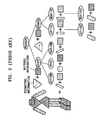
- FIG. 2 is a scene graph of a 3D human body structure.
- a body of a "person” is expressed in the 3D space.
- a "person” is roughly divided into “chest” and “stomach” parts, and the "chest” and the “stomach” are sub-nodes of the node “person”.
- sub-nodes of the "chest” include sub-nodes a "head” and a "right hand” and a “left hand” and sub-nodes of the "stomach” include a "left leg” and a “right leg”.
- Information in a high ranking node has a direct influence on a sub-node.
- the 3D graphics rendering engine includes a parser and a renderer.
- the parser reads in and interprets 3D graphics data. Namely, the parser identifies whether the read data is geometric information of an object, material information of an object, or information about a subordinate relationship between objects originated from the scene graph structure, and interpreting and judging the information.
- the renderer changes the scene graph parsed by the parser into a form appropriate for being played on a screen of an output device. Since a screen is appropriate for displaying 2D information, the scene graph expressed in 3D cannot be directly used.
- a primary role of the renderer is to convert 3D graphics data into 2D graphics data by performing a coordinate transformation on an object expressed in 3D space. Therefore, output data from the renderer is converted into 2D graphics data.
- the scene graph which is a method for expressing a data structure of the 3D graphic data, is an easy structure that can be easily understood and modified intuitively by a user as described above, but storage space is wasted, the generation of an output image is delayed, and image quality of the output image is deteriorated.
- FIG. 2 there exist nodes that include the same kinds of material information and such nodes are arranged in a discontinuous and irregular order.
- the renderer converts 3D graphics data of each node into 2D data without changing the scene graph's structure.
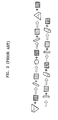
- FIG. 3 is a diagram illustrating an order of data conversion of the scene graph shown in FIG. 2.
- the renderer cannot be aware of such information during the rendering process. Therefore, the renderer repeatedly stores all material information appearing according to a predetermined order in a data storage space on a terminal. Therefore, when using the conventional 3D graphics rendering engine, waste of storage space occurs.
- the renderer throws away the original material information and reads the new material information into the storage space of the terminal.
- the process of reading or writing data from and to the storage space requires much time compared to other processes such as mathematical computation
- such information change causes a large delay in the whole process of converting 3D information into 2D information.
- the conventional 3D graphics rendering engine should always read material information due to a discontinuous arrangement of the same material information, the generation of an output image is delayed.
- information representing transparency of an object may be included in the information held by the 3D graphics data.
- the nodes having this information are arranged in a discontinuous and irregular order, exact conversion of 3D information into 2D information cannot be guaranteed.
- conversion of 3D information into 2D information should be performed by reflecting characteristics such as transparency, distance of other 3D objects existing in viewing frustum.
- the conventional 3D graphics rendering engine does not reflect transparency and distance between 3D objects that belong to each node, when determining a rendering order, deterioration in image quality of an output image occurs.
- an apparatus for reconstructing 3D graphics data including: a parsing unit for parsing 3D graphics data; an aligning unit for aligning nodes storing geometric information and material information that corresponds to the geometric information included in the 3D graphics data parsed by the parsing unit, and objects of a scene graph having hierarchy information regarding the nodes using predetermined detail information included in the material information as a reference; and a rendering unit for interpreting the objects of the scene graph aligned by the aligning unit to convert the 3D graphics data into 2D graphics data.
- a method of reconstructing 3D graphics data including: parsing 3D graphics data; aligning nodes storing geometric information and material information that corresponds to the geometric information included in the 3D graphics data, and objects of a scene graph having hierarchy information regarding the nodes using predetermined detail information included in the material information as a reference; and interpreting the aligned objects of the scene graph to convert the 3D graphics data into a 2D graphics data.
- the present invention provides an apparatus and method for reconstructing 3D graphic data capable of grouping nodes of a scene graph according to material information such as transparency information and texture information.
- FIG. 4 is a block diagram of an apparatus for reconstructing 3D graphics data according to an embodiment of the present invention, and the apparatus for reconstructing 3D graphics data includes a parsing unit 100, an aligning unit 120, and a rendering unit 140.
- the parsing unit 100 reads in and parses 3D graphics data such as VRML (Virtual Reality Modeling Language) data, or MPEG (Moving Picture Expert Group) data.
- the parsing unit 100 parses the scene graph of the 3D graphics data which is input through an input terminal IN1, and outputs information regarding the parsed scene graphs, to the aligning unit 120.
- the scene graph has nodes that include geographic information and material information that correspond to the geographic information, and also has hierarchy information of the nodes. Assume that detail information regarding geometric information and material information of the scene graphs, is an object of the scene graph.
- the geometric information is said to be 3D information representing the appearance of an object.
- the material information have each detail information.
- the detail information represents texture, transparency of an object, color of an object and shininess of an object's surface. Since the specific functions of the parsing unit 100 are the same as in the conventional art, a description thereof will be omitted.
- the aligning unit 120 aligns objects of the scene graph parsed by the parsing unit 100 using as a reference predetermined detail information included in the material information, and outputs the objects of the aligned scene graph to the rendering unit 140.
- aligning is performed on the transparency information and the texture information included in the predetermined detail information.
- the transparency information is divided into transparent geometric information and opaque geometric information depending on transparency. Transparent geometric information and opaque geometric information are separated and individually stored.
- the opaque geometric information is aligned according to texture information and the transparent geometric information is aligned in consideration of a distance between a camera and a position of the transparent geometric information.
- FIG. 5 is a block diagram of the aligning unit 120 shown in FIG. 4.
- the aligning unit includes a first scene graph interpreting unit 200, a detail information classifying unit 220, and a classification completion determination unit 260.
- the first scene graph interpreting unit 200 receives objects of the scene graph parsed by the parsing unit 100 via an input terminal IN2, and interprets the objects of the input scene graph and outputs the same to the detail information classifying unit 220.
- FIG. 6 is a block diagram of the first scene graph interpreting unit 200 shown in FIG. 5.
- the first scene graph interpreting unit 200 includes a shape node determination unit 300 and a sub-node detecting unit 320.
- the shape node determination unit 300 determines whether a node is a shape node of the scene graph, and outputs the determination results to the sub-node detecting unit 320 or to the detail information classifying unit 220 via an output terminal OUT3.
- a shape node is a node storing the geometric information and material information that corresponds to the geometric information. Since the shape node is a leaf node, the shape node does not have sub-nodes. If the node inspected by the shape node determination unit 300 is not a shape node, the inspected node is a group node having sub-nodes.
- the shape node determination unit 300 If the inspected node is a shape node, the shape node determination unit 300 outputs the determination results to the detail information classifying unit 220 via the output terminal OUT3. However, if the inspected node is not a shape node, the shape node determination unit 300 outputs the determination results to the sub-node detecting unit 320.
- the sub-node detecting unit 320 detects sub-nodes connected to a sub-hierarchy of the inspected node. If the determination results indicate that the inspected node has sub-nodes, the sub-node detecting unit 320 detects the sub-nodes in the sub-hierarchy of the inspected node, and outputs the detected results to the shape node determination unit 300.
- the shape node determination unit 300 determines whether the detected sub-nodes are shape nodes.
- the detail information classifying unit 220 classifies and stores the interpreted objects using predetermined detail information as a reference, and outputs the stored results to the classification completion determination unit 260.
- FIG. 7 is a block diagram of an embodiment for explaining the detail information classifying unit220 shown in FIG. 5.
- the detail information classifying unit 220 includes a matrix storage unit 400, a detail information access unit 420, a transparent geometric storage unit 440, and an opaque geometric storage unit 460.
- the matrix storage unit 400 determines which hierarchy of the scene graph the read shape node belongs to, computes a GTM (Global Transformation Matrix) capable of performing conversion from local coordinates of the relevant hierarchy to a global coordinates, stores the results in the read shape node, and outputs the read shape node to the detail information access unit 420.
- GTM Global Transformation Matrix
- the detail information access unit 420 reads predetermined detail information of the material information of the shape node.
- the detail information access unit 420 reads predetermined detail information of the material information of the interpreted shape node and outputs the same to the transparent geometric storage unit 440 or the opaque geometric storage unit 460 according to the predetermined detail information.
- the detail information access unit 420 reads texture information or transparency information of the predetermined detail information of the material information of the shape node. If the transparency information is transparent geometric information representing something transparent, the detail information access unit 420 outputs the read shape node to the transparent geometric storage unit 440; and if the transparency information is the opaque geometric information representing something opaque, the detail information access unit 420 outputs the read shape node to the opaque geometric storage unit 460.
- the transparent geometric storage unit 440 uses a one-dimensional array storage structure to store the read shape node. After a distance between the read shape node and a camera viewing the transparent geometric information is computed, the shape nodes are stored in the array, in which shape nodes which are distant from the camera are stored first, and shape nodes which are close to the camera are stored later. Such a storing order is intended to prevent image quality deterioration due to corruption of the transparent geometric information.
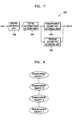
- FIG. 8 is a structural diagram for explaining a storage structure of transparent geometric information stored in the transparent geometric storage unit shown in FIG. 7.
- transparent geometric information of the shape node farther from the camera is stored in a transparent object 1.
- transparent geometric information of a shape node closer to the camera than the shape stored in the transparent object 1 is stored in a transparent object 2.
- Shape nodes successively closer to the camera are stored in a transparent object 3 and a transparent object 4, respectively.
- the opaque geometric storage unit 460 has a ring structure for storing texture information included in the detail information.
- the ring structure in which first data and last data are stored in adjacent storage units, denotes a storage structure of a linked list.
- the opaque geometric storage unit 460 determines whether texture information included in the detail information of the read shape node is already included in the ring. If the texture information is not included in the ring, the texture information is added to the ring and the opaque geometric information of the shape node is stored in a sub-ring of the texture information. If the texture information is already included in the ring, the texture information is not added to the ring, and the opaque geometric information of the shape node is stored in a sub-ring of the texture information which is already stored in the ring.
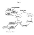
- FIG. 9 is a structural diagram for explaining a storage structure of opaque geometric information stored in the opaque geometric storage unit shown in FIG. 7.
- FIG. 9 exemplarily shows the texture information included in the detail information.
- the opaque geometric storage unit 460 uses a texture ring to store the texture information (texture 1, 2, 3, 4, and 5).
- texture information texture 1, 2, 3, 4, and 5
- the texture ring has sub-rings.
- opaque geometric information opaque geometric 1, 2, 3, 4, 5, and 6) including the texture of the texture information (1, 2, 3, 4, and 5
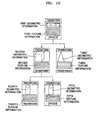
- FIG. 10 illustrates how a scene graph is reconstructed according to an embodiment of the present invention
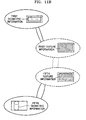
- FIGS. 11A and 11 B are diagrams illustrating the results after aligning the objects of the scene graph shown in FIG. 10.
- the scene graph shown in FIG. 10 is reconstructed with use of the aligning unit 120.
- the following description uses the array structure of the transparent geometric storage unit 440 exemplarily shown in FIG. 8 and the ring structure of the opaque geometric storage unit 460 shown in FIG. 9.
- the shape nodes of the scene graph are first classified according to the transparency information. If the shape node includes the transparent geometric information which is the transparent information, the shape node is stored in the transparent geometric storage unit 440 as shown in FIG. 11A. At this point, the order in which objects are stored in the transparent geometric storage unit 440 is determined according to the distance between the camera and the object. That is, an object that is farthest from the camera is aligned first. Therefore, referring to FIG. 11A, second, fourth, and third geometric information is stored in the given order in consideration of the distance from the camera.
- the texture ring is constructed using the texture information included in the shape nodes and the geometric information that includes the texture information is stored in the sub-rings of the texture information, as shown in FIG. 11 B. Therefore, the first and fifth texture information constitute the texture ring, and the first and the fifth geometric information constitute the sub-rings.
- the opaque geometric information includes the same texture information repeatedly, each piece of geometric information will be aligned in a sub-ring of a texture, which provides a structure in which large amounts of texture information can be processed in an efficient manner.
- the classification completion determination unit 260 determines whether all the objects of the interpreted scene graph are classified, and outputs the determination results via the output terminal OUT2. At this point, if not all nodes of the interpreted scene graph are classified completely with the predetermined detail information used as a reference, the classification completion determination unit 260 outputs the determination results to the first scene graph interpreting unit 200. The first scene graph interpreting unit 200 reinterprets the scene graph in response to the determination results of the classification completion determination unit 260.
- the scene graph is aligned based on each piece of texture information by the aligning unit, and thus the same texture information need not be stored repeatedly.
- the rendering unit 140 interprets the objects of the scene graphs aligned by the aligning unit 120 to convert 3D data into a 2D graphics data and outputs the converted 2D graphics data via the output terminal OUT1.
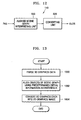
- FIG. 12 is a block diagram of an embodiment for explaining the rendering unit 140 shown in FIG. 4.
- the rendering unit 140 includes an aligned scene graph interpreting unit 500 and a converting unit 520.
- the aligned scene graph interpreting unit 500 interprets predetermined detail information received via an input terminal IN5 and the transparent and opaque geometric information that correspond to the predetermined detail information, and outputs the interpreted results to the converting unit 520.
- the aligned scene graph interpreting unit 500 receives the texture information and the opaque geometric information stored in the sub-ring of the received texture information from the aligning unit 120, and interprets the received texture information and the opaque geometric information. Also, the aligned scene graph interpreting unit 500 receives the transparent geometric information from the aligning unit 120 and interprets the received transparent geometric information.
- the converting unit 520 converts the predetermined detail information, the transparent geometric information, and the opaque geometric information into the 2D graphics data, and outputs the converted results via an output terminal OUT5.
- the converting unit 520 converts the 3D graphics data into the 2D graphics data starting with the transparent geometric information farthest from the camera and finished with the transparent geometric information closest to the camera, with respect to the interpreted transparent geometric information.
- the rendering unit 140 interprets and converts the opaque geometric information first, and then interprets and converts the transparent geometric information. If rendering is performed on the aligned transparent object after rendering is performed on the aligned opaque object, image quality deterioration that may be generated due to the transparent object can be prevented.
- FIG. 13 is a flowchart illustrating a method of reconstructing the 3D graphics data according to an embodiment of the present invention.
- the method includes: aligning objects of a scene graph of 3D graphics data using predetermined detail information as a reference and converting the 3D graphics data into a 2D graphics data using the aligned scene graph.
- the 3D graphics data is parsed (operation 1000).
- the scene graph among the 3D graphics data is also parsed.
- the scene graph includes the nodes that include geometric information and material information that corresponds to each piece of the geometric information.
- the scene graph also includes hierarchy information for the nodes.
- the objects of the scene graph of the 3D graphics data are aligned using the predetermined detail information of the material information as a reference (operation 1002).
- the aligned predetermined detail information is the transparency information and the texture information.
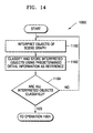
- FIG. 14 is a flowchart illustrating the operation 1002 shown in FIG. 13.
- the operation 1002 includes: classifying the objects of the scene graph using the predetermined detail information as a reference, and determining whether such objects are all classified.
- FIG. 15 is a flowchart illustrating the operation 1100 shown in FIG. 13.
- the operation 1100 includes operations 1200 and 1202 of detecting sub-nodes of each of the nodes depending on whether the inspected node is a shape node or not.
- the inspected node is not a shape node
- the sub-nodes connected to the inspected node are detected and the operation 1200 (operation 1202) is performed.
- the operation 1102 is performed.
- the objects of the interpreted scene graph are classified and stored using the predetermined detail information as a reference (operation 1102).
- FIG. 16 is a flowchart illustrating the operation 1102 shown in FIG. 14.
- the operation 1102 includes: reading the predetermined detail information of the material information and storing the transparent and opaque geometric information.
- a hierarchical position of the shape node is determined and a GTM is computed (operation 1300).
- the transparent and opaque geometric information included in the material information of the shape node are stored (operation 1304).
- the material information is opaque geometric information
- the opaque geometric information is stored in the sub-ring structure of the texture information
- the material information is transparent geometric information
- the transparent geometric information is stored in the array structure. That is, depending on the opaque geometric information included in the material information stored in the shape node, the material information is divided into transparent object lists and opaque object lists, and the transparent object lists are aligned according to a distance between the transparent object and a camera viewing the transparent object.
- One ring is constructed by the textures used for the opaque object list, and a sub-ring is constructed for each object that includes the same texture information and stored.
- the operation 1004 is performed. However, if the objects of the scene graph are not all classified, the operations 1100 through 1104 are performed.
- the aligned scene graph is interpreted and the 3D graphics data is converted into the 2D graphics data (operation 1004).
- the transparent geometric information is interpreted and converted.
- FIG. 17 is a flowchart illustrating the operation 1004 shown in FIG. 13.
- the predetermined detail information, and the transparent and opaque geometric information that correspond to the predetermined detail information are interpreted (operation 1400).
- the predetermined detail information, the transparent geometric information and the opaque geometric information are converted into the 2D graphics data (operation 1402).
- the 3D graphics data is converted into the 2D graphics data based on the order in which the transparent geometric information is aligned in operation 1304.
- 3D graphics data is classified according to its characteristics and the 3D graphics data is reconstructed according to the characteristics, whereby a fast and a more precise conversion of the 3D graphics data into a 2D graphics data is guaranteed and efficient management of the 3D graphics data is enhanced.
- characteristics of the present invention can be applied to a PC (personal computer) used in a fixed place and mobile devices such as a PDA (Personal Digital Assistant) or a cellular phone.
- an apparatus and method for reconstructing 3D graphics data according to the present invention can omit operations of repeatedly storing the same texture information by using an aligning unit to classify each node of a scene graph into groups according to texture information.
- the present invention classifies the geometric information by using the transparent information to sequentially perform data conversion according to the distance, from a viewing point, thereby converting the 3D graphics data into the 2D data in a more precise manner.
Landscapes
- Engineering & Computer Science (AREA)
- Physics & Mathematics (AREA)
- Theoretical Computer Science (AREA)
- General Physics & Mathematics (AREA)
- Computer Graphics (AREA)
- Business, Economics & Management (AREA)
- Geometry (AREA)
- Software Systems (AREA)
- Entrepreneurship & Innovation (AREA)
- Public Health (AREA)
- Educational Administration (AREA)
- Educational Technology (AREA)
- General Health & Medical Sciences (AREA)
- Epidemiology (AREA)
- Health & Medical Sciences (AREA)
- Image Generation (AREA)
- Processing Or Creating Images (AREA)
Applications Claiming Priority (2)
| Application Number | Priority Date | Filing Date | Title |
|---|---|---|---|
| KR2004027154 | 2004-04-20 | ||
| KR1020040027154A KR100601952B1 (ko) | 2004-04-20 | 2004-04-20 | 3차원 그래픽 데이터의 재구성장치 및 방법 |
Publications (2)
| Publication Number | Publication Date |
|---|---|
| EP1589487A2 true EP1589487A2 (de) | 2005-10-26 |
| EP1589487A3 EP1589487A3 (de) | 2006-11-15 |
Family
ID=34940850
Family Applications (1)
| Application Number | Title | Priority Date | Filing Date |
|---|---|---|---|
| EP05252360A Withdrawn EP1589487A3 (de) | 2004-04-20 | 2005-04-15 | Gerät und Verfahren zur Rekonstruktion von dreidimensionalen Grafikdaten |
Country Status (5)
| Country | Link |
|---|---|
| US (1) | US7593009B2 (de) |
| EP (1) | EP1589487A3 (de) |
| JP (1) | JP2005310160A (de) |
| KR (1) | KR100601952B1 (de) |
| CN (1) | CN1691068A (de) |
Families Citing this family (23)
| Publication number | Priority date | Publication date | Assignee | Title |
|---|---|---|---|---|
| KR20070049774A (ko) * | 2005-11-09 | 2007-05-14 | 김인한 | 다차원 모델을 2차원의 도면으로 작성하는 방법 |
| CN100388318C (zh) * | 2005-11-28 | 2008-05-14 | 北京航空航天大学 | 一种基于状态集的Shader三维图形绘制系统和绘制方法 |
| KR20070092499A (ko) * | 2006-03-10 | 2007-09-13 | 삼성전자주식회사 | 3차원 그래픽 데이터의 처리 방법 및 장치 |
| CN100435171C (zh) * | 2006-03-31 | 2008-11-19 | 北京北大方正电子有限公司 | 一种三维图形排列的方法 |
| US7408550B2 (en) * | 2006-07-24 | 2008-08-05 | Bunnell Michael T | System and methods for real-time rendering of deformable geometry with global illumination |
| US9019300B2 (en) * | 2006-08-04 | 2015-04-28 | Apple Inc. | Framework for graphics animation and compositing operations |
| KR100829564B1 (ko) | 2006-09-29 | 2008-05-14 | 삼성전자주식회사 | 효율적으로 모션 블러 효과를 제공하는 3차원 그래픽스렌더링 방법 및 장치 |
| US8117541B2 (en) * | 2007-03-06 | 2012-02-14 | Wildtangent, Inc. | Rendering of two-dimensional markup messages |
| KR100885547B1 (ko) * | 2007-04-23 | 2009-02-26 | 주식회사 지니프릭스 | 디지털 대화형 방송을 위한 3차원 그래픽 형성 방법, 상기방법을 이용한 3차원 그래픽 형성 시스템 |
| KR100901284B1 (ko) * | 2007-10-23 | 2009-06-09 | 한국전자통신연구원 | 3d 모델 식별자를 이용한 랜더링 시스템 및 방법 |
| US8612485B2 (en) * | 2008-08-11 | 2013-12-17 | Sony Corporation | Deferred 3-D scenegraph processing |
| US20100073379A1 (en) * | 2008-09-24 | 2010-03-25 | Sadan Eray Berger | Method and system for rendering real-time sprites |
| US8935129B1 (en) * | 2010-06-04 | 2015-01-13 | Bentley Systems, Incorporated | System and method for simplifying a graph'S topology and persevering the graph'S semantics |
| US9436868B2 (en) * | 2010-09-10 | 2016-09-06 | Dimensional Photonics International, Inc. | Object classification for measured three-dimensional object scenes |
| US8655810B2 (en) * | 2010-10-22 | 2014-02-18 | Samsung Electronics Co., Ltd. | Data processing apparatus and method for motion synthesis |
| US20140078144A1 (en) * | 2012-09-14 | 2014-03-20 | Squee, Inc. | Systems and methods for avatar creation |
| US20150088474A1 (en) * | 2013-09-25 | 2015-03-26 | Ford Global Technologies, Llc | Virtual simulation |
| EP3063737B1 (de) | 2013-10-28 | 2020-05-06 | Thomson Licensing | Verfahren und vorrichtung zur herstellung einer grafischen darstellung eines 3d-objekts |
| US10565802B2 (en) * | 2017-08-31 | 2020-02-18 | Disney Enterprises, Inc. | Collaborative multi-modal mixed-reality system and methods leveraging reconfigurable tangible user interfaces for the production of immersive, cinematic, and interactive content |
| CN107818594A (zh) * | 2017-09-06 | 2018-03-20 | 北京矩阵空间科技有限公司 | 三维模型文件格式系统及读取方法 |
| CN109949267B (zh) * | 2019-01-21 | 2021-01-29 | 西安交通大学 | 一种多材料断层数据到实体的快速三维重构方法 |
| CN112785680B (zh) * | 2019-11-07 | 2023-01-24 | 上海莉莉丝科技股份有限公司 | 描述三维虚拟空间中物体关系的方法、系统、设备和介质 |
| CN119127022A (zh) * | 2024-09-06 | 2024-12-13 | 江苏金顺软件有限公司 | 一种三维立体呈现式智能操作系统及其交互式方法 |
Family Cites Families (3)
| Publication number | Priority date | Publication date | Assignee | Title |
|---|---|---|---|---|
| US6369812B1 (en) | 1997-11-26 | 2002-04-09 | Philips Medical Systems, (Cleveland), Inc. | Inter-active viewing system for generating virtual endoscopy studies of medical diagnostic data with a continuous sequence of spherical panoramic views and viewing the studies over networks |
| US6771264B1 (en) * | 1998-08-20 | 2004-08-03 | Apple Computer, Inc. | Method and apparatus for performing tangent space lighting and bump mapping in a deferred shading graphics processor |
| US7511718B2 (en) * | 2003-10-23 | 2009-03-31 | Microsoft Corporation | Media integration layer |
-
2004
- 2004-04-20 KR KR1020040027154A patent/KR100601952B1/ko not_active Expired - Fee Related
-
2005
- 2005-03-17 CN CNA2005100551236A patent/CN1691068A/zh active Pending
- 2005-04-15 EP EP05252360A patent/EP1589487A3/de not_active Withdrawn
- 2005-04-19 US US11/108,818 patent/US7593009B2/en not_active Expired - Fee Related
- 2005-04-20 JP JP2005122352A patent/JP2005310160A/ja not_active Withdrawn
Non-Patent Citations (3)
| Title |
|---|
| OPENSG CORE TEAM: "OpenSG Starter Guide 1.2.0"[Online] 19 March 2003 (2003-03-19), pages 1-65, XP002394586 Retrieved from the Internet: URL:http://www.opensg.org/downloads/OpenSG -1.2.0-UserStarter.pdf> [retrieved on 2006-08-11] * |
| SOMMER O ET AL: "Geometry and rendering optimizations for the interactive visualization of crash-worthiness simulations" PROCEEDINGS OF THE SPIE - THE INTERNATIONAL SOCIETY FOR OPTICAL ENGINEERING SPIE-INT. SOC. OPT. ENG USA, vol. 3960, 2000, pages 124-134, XP002394741 ISSN: 0277-786X * |
| STANEKER D ET AL: "Occlusion Culling in OpenSG PLUS" COMPUTERS AND GRAPHICS, PERGAMON PRESS LTD. OXFORD, GB, vol. 28, no. 1, February 2004 (2004-02), pages 87-92, XP004484897 ISSN: 0097-8493 * |
Also Published As
| Publication number | Publication date |
|---|---|
| EP1589487A3 (de) | 2006-11-15 |
| US7593009B2 (en) | 2009-09-22 |
| KR20050101915A (ko) | 2005-10-25 |
| KR100601952B1 (ko) | 2006-07-14 |
| CN1691068A (zh) | 2005-11-02 |
| JP2005310160A (ja) | 2005-11-04 |
| US20050234946A1 (en) | 2005-10-20 |
Similar Documents
| Publication | Publication Date | Title |
|---|---|---|
| US7593009B2 (en) | Apparatus and method for reconstructing three-dimensional graphics data | |
| US12154228B2 (en) | Methods and systems for producing content in multiple reality environments | |
| US20090295791A1 (en) | Three-dimensional environment created from video | |
| CN113706713A (zh) | 一种实景三维模型裁剪方法、装置及计算机设备 | |
| CN110809788B (zh) | 深度图像的融合方法、装置和计算机可读存储介质 | |
| CN102812497A (zh) | 能够提供随后体验影像的影像提供装置、影像提供方法、影像提供程序 | |
| US20240020915A1 (en) | Generative model for 3d face synthesis with hdri relighting | |
| CN110211206B (zh) | 一种计算机动画制作系统 | |
| JP2024513005A (ja) | イマーシブテクノロジーズメディアフォーマット(itmf)仕様のマッピングアーキテクチャのための方法、装置、及びコンピュータプログラム | |
| Behravan et al. | Transcending dimensions using generative AI: Real-time 3D model generation in augmented reality | |
| Peng et al. | Large-scale single-pixel imaging and sensing | |
| CN114064187A (zh) | 一种跨渲染引擎的中间装置、数据处理方法及存储介质 | |
| JP2023047882A (ja) | 画像生成装置、画像生成方法およびプログラム | |
| CN116450869A (zh) | 全景图像数据处理方法和系统、电子设备及存储介质 | |
| JP5175794B2 (ja) | 情報処理装置、情報処理方法、およびプログラム | |
| KR20170006219A (ko) | 3차원 모델링 서비스 제공 방법 및 이를 위한 장치 | |
| JP2019149112A (ja) | 合成装置、方法及びプログラム | |
| JP2020101922A (ja) | 画像処理装置、画像処理方法およびプログラム | |
| Lu et al. | GPU-based real-time occlusion in an immersive augmented reality environment | |
| CN116260952A (zh) | 一种基于最大变化方向的点云帧序列压缩方法 | |
| CN202512630U (zh) | 一种真三维道路勘察设计项目演示汇报系统 | |
| KR102925425B1 (ko) | 데이터 스냅샷 획득을 위한 사용자 인터랙션의 구현 방법 및 그러한 방법이 구현되는 컴퓨팅 장치 | |
| CN121214146B (zh) | 人体与物体接触预测方法、装置、电子设备及存储介质 | |
| CN115100666B (zh) | 基于显著性检测和超分辨率重建的ar会议系统及构建方法 | |
| WO2021134970A1 (zh) | 图像语义分割方法及装置、存储介质 |
Legal Events
| Date | Code | Title | Description |
|---|---|---|---|
| PUAI | Public reference made under article 153(3) epc to a published international application that has entered the european phase |
Free format text: ORIGINAL CODE: 0009012 |
|
| AK | Designated contracting states |
Kind code of ref document: A2 Designated state(s): AT BE BG CH CY CZ DE DK EE ES FI FR GB GR HU IE IS IT LI LT LU MC NL PL PT RO SE SI SK TR |
|
| AX | Request for extension of the european patent |
Extension state: AL BA HR LV MK YU |
|
| PUAL | Search report despatched |
Free format text: ORIGINAL CODE: 0009013 |
|
| AK | Designated contracting states |
Kind code of ref document: A3 Designated state(s): AT BE BG CH CY CZ DE DK EE ES FI FR GB GR HU IE IS IT LI LT LU MC NL PL PT RO SE SI SK TR |
|
| AX | Request for extension of the european patent |
Extension state: AL BA HR LV MK YU |
|
| 17P | Request for examination filed |
Effective date: 20070314 |
|
| 17Q | First examination report despatched |
Effective date: 20070411 |
|
| AKX | Designation fees paid |
Designated state(s): DE FR GB |
|
| STAA | Information on the status of an ep patent application or granted ep patent |
Free format text: STATUS: THE APPLICATION IS DEEMED TO BE WITHDRAWN |
|
| 18D | Application deemed to be withdrawn |
Effective date: 20101103 |