EP1589276A2 - Device for the construction of bases - Google Patents
Device for the construction of bases Download PDFInfo
- Publication number
- EP1589276A2 EP1589276A2 EP05380079A EP05380079A EP1589276A2 EP 1589276 A2 EP1589276 A2 EP 1589276A2 EP 05380079 A EP05380079 A EP 05380079A EP 05380079 A EP05380079 A EP 05380079A EP 1589276 A2 EP1589276 A2 EP 1589276A2
- Authority
- EP
- European Patent Office
- Prior art keywords
- plate
- slab
- bases
- lower plate
- stud
- Prior art date
- Legal status (The legal status is an assumption and is not a legal conclusion. Google has not performed a legal analysis and makes no representation as to the accuracy of the status listed.)
- Granted
Links
Images


Classifications
-
- F—MECHANICAL ENGINEERING; LIGHTING; HEATING; WEAPONS; BLASTING
- F16—ENGINEERING ELEMENTS AND UNITS; GENERAL MEASURES FOR PRODUCING AND MAINTAINING EFFECTIVE FUNCTIONING OF MACHINES OR INSTALLATIONS; THERMAL INSULATION IN GENERAL
- F16M—FRAMES, CASINGS OR BEDS OF ENGINES, MACHINES OR APPARATUS, NOT SPECIFIC TO ENGINES, MACHINES OR APPARATUS PROVIDED FOR ELSEWHERE; STANDS; SUPPORTS
- F16M5/00—Engine beds, i.e. means for supporting engines or machines on foundations
Definitions
- the subject of this invention consists in a Device for the construction of bases , usable in the assembly of bases of the seating for machinery and for floating floors, with the special feature that these bases can be dismantled and reused in a different location.
- Utility model No U200301656 is known, the subject of which is a device for the construction of bases basically consisting in a modular assembly composed of two elements, a slab of concrete, iron or other suitable material and a slab union element, enabling a modular base to be created which can be dismantled so that when the machine has to be removed or its location changed, the base can be dismantled and reassembled in another place, its form being able to be changed, reduced or extended.
- the slab union element consists of two plates, one lower and the other upper, both preferably of a polygonal shape.
- the lower has at least two tubular extensions internally threaded, fixed perpendicularly to that plate while the upper has perforations vertically matching the tubular extensions of the lower plate; bolts are introduced vertically into these perforations and screwed into the tubular extensions of the lower plate, slab-lower plate-upper plate assembly being in this way made solid and stabilised.
- This form of assembly basically presents two drawbacks: To introduce the tubular extensions of the lower plate into the slab, the slab has to be partially lifted and this represents an added difficulty, particularly if this slab is already attached to another or others, as the weight of these slabs could be substantial.
- the base will also not be level, or auxiliary elements would have to be used to level it up.
- the invention consists in a modular assembly composed of two elements, a slab of concrete or other suitable material and a slab union element, enabling the a modular base to be created which can be dismantled and reused should it have to be removed or the placing of the base changed.
- the slab union element is formed by two plates, one lower, and the other upper, of which the lower has a minimum of two perforations, both with suitable threading to receive a bolt passing through for its fixing to the upper plate.
- the threading can be made in the body of the plate itself or can be in two nuts applied to the lower face of that plate, and preferably secured by welding or any other similar method. In this way it is not necessary for the slab to be partially lifted in order to place the lower plate.
- the upper plate is formed by two parts fitted together with a dovetail joint. This means that one upper part can be placed first and bolted to the lower plate and then, if necessary, the second upper part can be fitted to the first and in its turn bolted through the corresponding perforation in the lower plate.
- the slabs constituting the base are preferably polygonal in shape, with at least one area of seating for the union element in each of its sides, distributed on both the upper face and the lower face, where the respective two parts of the upper plate and the lower plate are coupled.
- These seating areas are formed by recesses in the corresponding surfaces of the slab, which in the case of the upper ones are of equal or greater depth than the thickness of the upper plate of the union element plus the thickness of the head of the bolt or the nut, while for the lower ones this recess has a minimum depth of the thickness of the lower plate.
- each seating area has a perforation through it to match the perforation in the corresponding part of the upper plate of the union element and the corresponding perforation in the lower plate.
- These perforations have sufficient diameter for the insertion in them of the bolts or threaded studs and will all be lined up at the precise moment that the bolt or stud is introduced.
- the lower plate, the slab and the corresponding part of the upper plate will become solidly assembled at the moment that the lower nut is screwed tight.
- the method of operating the assembly of the bases is very simple: the slabs must be attached two by two using the union element. To do this the lower plate is slipped horizontally below the slab along the corresponding seating until one of its perforations is lined up with the perforation in the slab. Then one of the two parts forming the upper plate is placed in the upper seating of one of the two slabs, in such a way that its perforation is also lined up with the perforation in the slab. Then a bolt is passed through the lined up perforations and screwed to the nut located below the lower plate and fixed to it.
- the second of the two parts forming the upper plate and dovetailed to the first is fitted in the upper seating of the other slab, after which it is screwed down by the bolt or stud to the nut located under the lower plate, thus making the whole assembly solid.
- a stud of variable length is used, supported on a foot of flexible material (preferably protected by a metal plate with a recess into which the stud can fit), the height of the base over the substratum can be adjusted to ensure that the base is levelled; the surplus stud being cut off level with the upper surface of the slab.
- the main purpose of the foot of flexible material (rubber or similar) is to act as an absorbent material for the vibrations and shocks that the machine placed on the base may produce. These feet can be replaced by continuous plates with mechanical characteristics giving the same levelling and shock-absorbing effect.
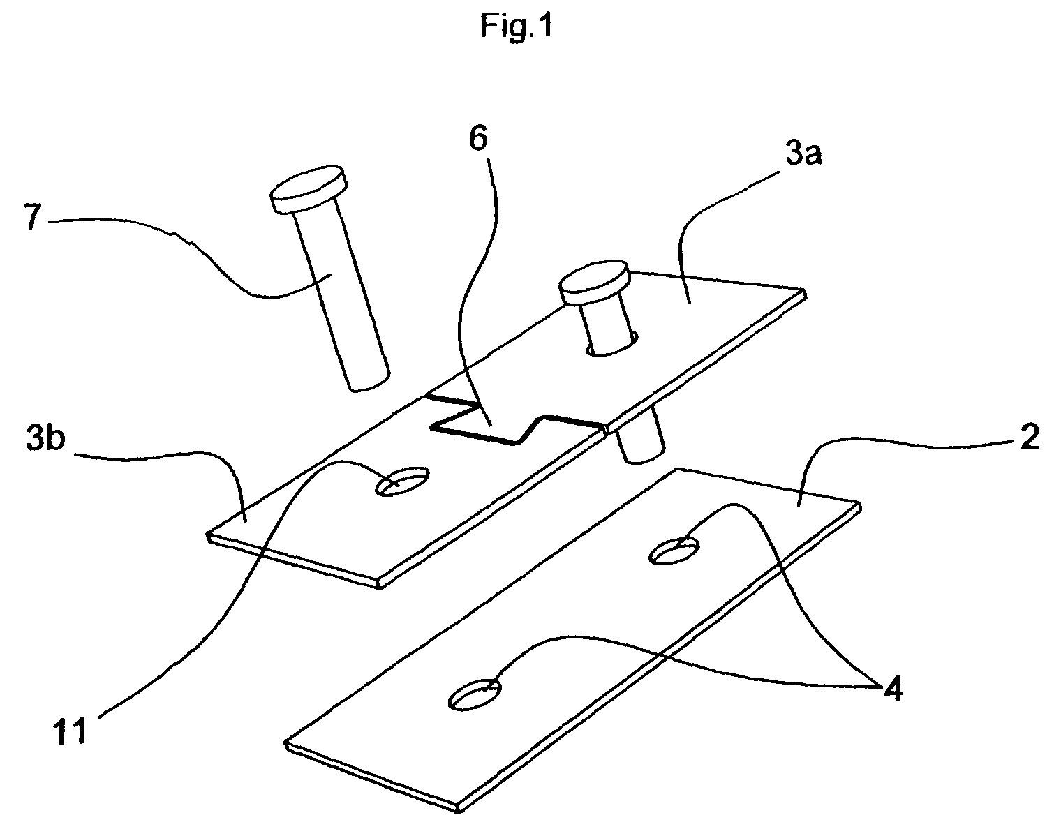
- the novel device for the construction of bases is composed of two elements, a concrete slab (1) and a slab union element formed by two plates, a lower (2), and an upper (3).
- the lower plate (2) has two perforations (4) under which and resting against the lower face are two nuts (5) fixed by welding.
- the upper plate (3) is formed by two parts (3a) and (3b) united by a dovetail joint (6), and fixed solidly to the lower plate (2) by two bolts (7).
- Each of these parts (3a) and (3b) has a perforation (11) made to match the perforations (4) in the lower plate (2).
- the slabs (1) have on each of their sides an upper seating area (8) for the upper plate (3), and a lower seating area (9) for the lower plate (2).
- These seating areas (8) and (9) are formed by a recess in the corresponding surfaces of the slab (1), which in the case of the upper ones (8) is of a depth equal to the thickness of the upper plate (3) of the union element plus the thickness of the head of the bolt (7), while in the lower ones the depth of the recess corresponds to the thickness of the lower plate (2).
- each seating area has a perforation through it (10) matching the perforations (4) and (11) of the union element.
- the screws (7) are replaced by a headless threaded stud (12), which passes through the whole assembly, resting its lower end on a foot of flexible material (13) fitted with a metal plate (14) with a recess (15) in which the stud rests, while a nut (16) is fitted to its upper end which is adjusted on the upper plate (3).
- this threaded stud (12) By altering the position of this threaded stud (12) the height of the base can be adjusted over the substratum in order to level it, correcting irregularities in the substratum.
Landscapes
- Engineering & Computer Science (AREA)
- General Engineering & Computer Science (AREA)
- Mechanical Engineering (AREA)
- Forms Removed On Construction Sites Or Auxiliary Members Thereof (AREA)
- Paper (AREA)
- Electrical Discharge Machining, Electrochemical Machining, And Combined Machining (AREA)
- Body Structure For Vehicles (AREA)
- Joining Of Building Structures In Genera (AREA)
- Road Paving Structures (AREA)
- Threshing Machine Elements (AREA)
- Buildings Adapted To Withstand Abnormal External Influences (AREA)
- Underground Structures, Protecting, Testing And Restoring Foundations (AREA)
- Iron Core Of Rotating Electric Machines (AREA)
- Bridges Or Land Bridges (AREA)
- Air Bags (AREA)
- Transplanting Machines (AREA)
- Floor Finish (AREA)
Abstract
Description
The lower plate (2) has two perforations (4) under which and resting against the lower face are two nuts (5) fixed by welding.
Claims (3)
- "Device for the construction of bases" of the type composed of two elements, concrete slabs and slab union elements formed by two plates, one lower and another upper, characterised essentially because the lower plate has at least two perforations both with threads suitable to receive a bolt or stud for their fixing to the upper plate, which is formed by two parts united by a dovetail joint, each with a perforation to match those of the lower plate.
- "Device for the construction of bases" according to the above claim, characterised because the thread of the lower plate of the slab union elements is made in the body of the plate itself and or is constituted by the respective nuts, supported coaxially with the perforations, on the lower face of this plate, secured to it by welding or other similar method.
- "Device for the construction of bases" according to the above claims, characterised because in the cases in which the slab union elements are joined by a threaded stud, the lower end of this is seated on a foot of material reinforced by a metal plate with a recess where the stud rests, and the upper end receives a nut which is adjusted on the upper plate.
Priority Applications (3)
| Application Number | Priority Date | Filing Date | Title |
|---|---|---|---|
| SI200530031T SI1589276T1 (en) | 2004-04-20 | 2005-04-19 | Device for the construction of bases |
| PL05380079T PL1589276T3 (en) | 2004-04-20 | 2005-04-19 | Device for the construction of bases |
| CY20071100970T CY1107073T1 (en) | 2004-04-20 | 2007-07-20 | ORDER FOR BASE CONSTRUCTION |
Applications Claiming Priority (2)
| Application Number | Priority Date | Filing Date | Title |
|---|---|---|---|
| ES200400928 | 2004-04-20 | ||
| ES200400928U ES1057260Y (en) | 2004-04-20 | 2004-04-20 | DEVICE FOR THE CONSTRUCTION OF BASEMENTS. |
Publications (3)
| Publication Number | Publication Date |
|---|---|
| EP1589276A2 true EP1589276A2 (en) | 2005-10-26 |
| EP1589276A3 EP1589276A3 (en) | 2006-01-18 |
| EP1589276B1 EP1589276B1 (en) | 2007-05-02 |
Family
ID=32696034
Family Applications (1)
| Application Number | Title | Priority Date | Filing Date |
|---|---|---|---|
| EP05380079A Expired - Lifetime EP1589276B1 (en) | 2004-04-20 | 2005-04-19 | Device for the construction of bases |
Country Status (9)
| Country | Link |
|---|---|
| EP (1) | EP1589276B1 (en) |
| AT (1) | ATE361446T1 (en) |
| CY (1) | CY1107073T1 (en) |
| DE (1) | DE602005001016T2 (en) |
| DK (1) | DK1589276T3 (en) |
| ES (1) | ES1057260Y (en) |
| PL (1) | PL1589276T3 (en) |
| PT (1) | PT1589276E (en) |
| SI (1) | SI1589276T1 (en) |
Cited By (2)
| Publication number | Priority date | Publication date | Assignee | Title |
|---|---|---|---|---|
| CN109629729A (en) * | 2018-12-19 | 2019-04-16 | 哈尔滨达城绿色建筑技术开发股份有限公司 | A kind of glomeration building unidirectional precast hollow slab superposed floor in gradual change section |
| GB2569607A (en) * | 2017-12-21 | 2019-06-26 | Laing Orourke Plc | Demountable floor construction |
Family Cites Families (5)
| Publication number | Priority date | Publication date | Assignee | Title |
|---|---|---|---|---|
| FR2349004A2 (en) * | 1976-04-21 | 1977-11-18 | Saret | Concrete floor panel structure - has prestressed concrete, beams held in position by end spandrels and has panels holding in insulation |
| DE3634568C2 (en) * | 1986-01-20 | 1995-07-27 | Dennert Kg Veit | Clamping element for connecting precast concrete parts |
| FR2712013A1 (en) * | 1993-11-03 | 1995-05-12 | Elasto Technologies Wood Milne | Modifiable surface covering, key (wedge) and sheet for such a covering |
| SE511080C2 (en) * | 1997-12-15 | 1999-08-02 | Peab Ab | Prefabricated floor tile element with molded pipes for water or drain |
| ES1055051Y (en) * | 2003-07-10 | 2004-01-16 | Colomer Ines Jackson | DEVICE FOR THE CONSTRUCTION OF BASES |
-
2004
- 2004-04-20 ES ES200400928U patent/ES1057260Y/en not_active Expired - Fee Related
-
2005
- 2005-04-19 PT PT05380079T patent/PT1589276E/en unknown
- 2005-04-19 EP EP05380079A patent/EP1589276B1/en not_active Expired - Lifetime
- 2005-04-19 SI SI200530031T patent/SI1589276T1/en unknown
- 2005-04-19 DE DE602005001016T patent/DE602005001016T2/en not_active Expired - Lifetime
- 2005-04-19 AT AT05380079T patent/ATE361446T1/en not_active IP Right Cessation
- 2005-04-19 DK DK05380079T patent/DK1589276T3/en active
- 2005-04-19 PL PL05380079T patent/PL1589276T3/en unknown
-
2007
- 2007-07-20 CY CY20071100970T patent/CY1107073T1/en unknown
Cited By (3)
| Publication number | Priority date | Publication date | Assignee | Title |
|---|---|---|---|---|
| GB2569607A (en) * | 2017-12-21 | 2019-06-26 | Laing Orourke Plc | Demountable floor construction |
| GB2569607B (en) * | 2017-12-21 | 2020-03-04 | Laing Orourke Plc | Demountable floor construction |
| CN109629729A (en) * | 2018-12-19 | 2019-04-16 | 哈尔滨达城绿色建筑技术开发股份有限公司 | A kind of glomeration building unidirectional precast hollow slab superposed floor in gradual change section |
Also Published As
| Publication number | Publication date |
|---|---|
| SI1589276T1 (en) | 2007-10-31 |
| CY1107073T1 (en) | 2012-10-24 |
| ATE361446T1 (en) | 2007-05-15 |
| EP1589276B1 (en) | 2007-05-02 |
| PT1589276E (en) | 2007-08-06 |
| DK1589276T3 (en) | 2007-09-17 |
| DE602005001016T2 (en) | 2008-01-10 |
| DE602005001016D1 (en) | 2007-06-14 |
| ES1057260Y (en) | 2004-10-16 |
| ES1057260U (en) | 2004-07-01 |
| EP1589276A3 (en) | 2006-01-18 |
| PL1589276T3 (en) | 2007-09-28 |
Similar Documents
| Publication | Publication Date | Title |
|---|---|---|
| EP0704012B1 (en) | Supporting element | |
| CN114127366A (en) | Column shoe for fastening a reinforced concrete column to a base | |
| EP1589276B1 (en) | Device for the construction of bases | |
| US5353987A (en) | Railroad track system having vertically adjustable railroad tie and method of construction therefor | |
| JP3217925B2 (en) | Bridge structure and construction method | |
| KR100622023B1 (en) | A supporter of a road boundary stone and the using method thereof | |
| JPH08105115A (en) | Connection method of column and beam | |
| KR20220072550A (en) | Supporting structure for reusable temporary transmission tower | |
| KR101259362B1 (en) | Construction system of expansion joint for bridge | |
| JPH062313A (en) | Level adjustment of bearing part | |
| US6899535B2 (en) | Apparatus for forming concrete foundations | |
| JPH01102105A (en) | Method for fixing precast concrete floor panel and steel beam | |
| JP4211537B2 (en) | Concrete block manufacturing method and manufacturing jig | |
| US7018133B2 (en) | Concrete finishing screed | |
| JP2006322154A (en) | Foundation construction method of building | |
| JP2021105272A (en) | Precast floor slab construction method | |
| JP2002097791A (en) | Form support metal | |
| JP2002212957A (en) | Precast foundation constructing method and constructing jig | |
| JP2006233669A (en) | Method of widening bridge sidewalk, and bridge sidewalk structure | |
| JP4149117B2 (en) | Method for performing column base concrete splicing and driving form for a splicing portion used in the method | |
| KR20100024732A (en) | Seat apparatus for a bridge of i.l.m type and the method thereof | |
| JP2004150016A (en) | Floor repair method and floor structure | |
| JP2640867B2 (en) | Bundle height adjustment bracket | |
| JP2025082060A (en) | Support structure for precast concrete member | |
| JPH08100532A (en) | Joining method for beam support and beam member |
Legal Events
| Date | Code | Title | Description |
|---|---|---|---|
| PUAI | Public reference made under article 153(3) epc to a published international application that has entered the european phase |
Free format text: ORIGINAL CODE: 0009012 |
|
| AK | Designated contracting states |
Kind code of ref document: A2 Designated state(s): AT BE BG CH CY CZ DE DK EE ES FI FR GB GR HU IE IS IT LI LT LU MC NL PL PT RO SE SI SK TR |
|
| AX | Request for extension of the european patent |
Extension state: AL BA HR LV MK YU |
|
| PUAL | Search report despatched |
Free format text: ORIGINAL CODE: 0009013 |
|
| AK | Designated contracting states |
Kind code of ref document: A3 Designated state(s): AT BE BG CH CY CZ DE DK EE ES FI FR GB GR HU IE IS IT LI LT LU MC NL PL PT RO SE SI SK TR |
|
| AX | Request for extension of the european patent |
Extension state: AL BA HR LV MK YU |
|
| RIC1 | Information provided on ipc code assigned before grant |
Ipc: E04B 5/08 20060101ALI20051130BHEP Ipc: F16M 5/00 20060101AFI20050728BHEP Ipc: E04B 5/02 20060101ALI20051130BHEP Ipc: E04B 5/06 20060101ALI20051130BHEP |
|
| 17P | Request for examination filed |
Effective date: 20060529 |
|
| AKX | Designation fees paid |
Designated state(s): AT BE BG CH CY CZ DE DK EE ES FI FR GB GR HU IE IS IT LI LT LU MC NL PL PT RO SE SI SK TR |
|
| GRAP | Despatch of communication of intention to grant a patent |
Free format text: ORIGINAL CODE: EPIDOSNIGR1 |
|
| GRAS | Grant fee paid |
Free format text: ORIGINAL CODE: EPIDOSNIGR3 |
|
| GRAA | (expected) grant |
Free format text: ORIGINAL CODE: 0009210 |
|
| AK | Designated contracting states |
Kind code of ref document: B1 Designated state(s): AT BE BG CH CY CZ DE DK EE ES FI FR GB GR HU IE IS IT LI LT LU MC NL PL PT RO SE SI SK TR |
|
| REG | Reference to a national code |
Ref country code: GB Ref legal event code: FG4D |
|
| REG | Reference to a national code |
Ref country code: CH Ref legal event code: EP |
|
| REG | Reference to a national code |
Ref country code: IE Ref legal event code: FG4D |
|
| REF | Corresponds to: |
Ref document number: 602005001016 Country of ref document: DE Date of ref document: 20070614 Kind code of ref document: P |
|
| REG | Reference to a national code |
Ref country code: RO Ref legal event code: EPE |
|
| REG | Reference to a national code |
Ref country code: PT Ref legal event code: SC4A Free format text: AVAILABILITY OF NATIONAL TRANSLATION Effective date: 20070725 |
|
| PG25 | Lapsed in a contracting state [announced via postgrant information from national office to epo] |
Ref country code: ES Free format text: LAPSE BECAUSE OF FAILURE TO SUBMIT A TRANSLATION OF THE DESCRIPTION OR TO PAY THE FEE WITHIN THE PRESCRIBED TIME-LIMIT Effective date: 20070813 |
|
| REG | Reference to a national code |
Ref country code: SE Ref legal event code: TRGR |
|
| REG | Reference to a national code |
Ref country code: CH Ref legal event code: NV Representative=s name: KATZAROV S.A. |
|
| PG25 | Lapsed in a contracting state [announced via postgrant information from national office to epo] |
Ref country code: IS Free format text: LAPSE BECAUSE OF FAILURE TO SUBMIT A TRANSLATION OF THE DESCRIPTION OR TO PAY THE FEE WITHIN THE PRESCRIBED TIME-LIMIT Effective date: 20070902 |
|
| REG | Reference to a national code |
Ref country code: GR Ref legal event code: EP Ref document number: 20070402249 Country of ref document: GR |
|
| REG | Reference to a national code |
Ref country code: DK Ref legal event code: T3 |
|
| REG | Reference to a national code |
Ref country code: PL Ref legal event code: T3 |
|
| ET | Fr: translation filed | ||
| REG | Reference to a national code |
Ref country code: EE Ref legal event code: FG4A Ref document number: E001567 Country of ref document: EE Effective date: 20070801 |
|
| REG | Reference to a national code |
Ref country code: HU Ref legal event code: AG4A Ref document number: E002126 Country of ref document: HU |
|
| REG | Reference to a national code |
Ref country code: EE Ref legal event code: HC1A Ref document number: E001567 Country of ref document: EE |
|
| PG25 | Lapsed in a contracting state [announced via postgrant information from national office to epo] |
Ref country code: LT Free format text: LAPSE BECAUSE OF FAILURE TO SUBMIT A TRANSLATION OF THE DESCRIPTION OR TO PAY THE FEE WITHIN THE PRESCRIBED TIME-LIMIT Effective date: 20070502 |
|
| PLBE | No opposition filed within time limit |
Free format text: ORIGINAL CODE: 0009261 |
|
| STAA | Information on the status of an ep patent application or granted ep patent |
Free format text: STATUS: NO OPPOSITION FILED WITHIN TIME LIMIT |
|
| 26N | No opposition filed |
Effective date: 20080205 |
|
| PG25 | Lapsed in a contracting state [announced via postgrant information from national office to epo] |
Ref country code: MC Free format text: LAPSE BECAUSE OF NON-PAYMENT OF DUE FEES Effective date: 20080430 |
|
| REG | Reference to a national code |
Ref country code: EE Ref legal event code: HC1A Ref document number: E001567 Country of ref document: EE |
|
| PGFP | Annual fee paid to national office [announced via postgrant information from national office to epo] |
Ref country code: BG Payment date: 20100430 Year of fee payment: 6 Ref country code: DK Payment date: 20100421 Year of fee payment: 6 Ref country code: FI Payment date: 20100429 Year of fee payment: 6 Ref country code: FR Payment date: 20100519 Year of fee payment: 6 Ref country code: HU Payment date: 20100423 Year of fee payment: 6 Ref country code: IE Payment date: 20100420 Year of fee payment: 6 Ref country code: LU Payment date: 20100506 Year of fee payment: 6 Ref country code: PT Payment date: 20100415 Year of fee payment: 6 Ref country code: RO Payment date: 20100419 Year of fee payment: 6 |
|
| PGFP | Annual fee paid to national office [announced via postgrant information from national office to epo] |
Ref country code: AT Payment date: 20100422 Year of fee payment: 6 Ref country code: CZ Payment date: 20100416 Year of fee payment: 6 Ref country code: DE Payment date: 20100419 Year of fee payment: 6 Ref country code: EE Payment date: 20100415 Year of fee payment: 6 Ref country code: IT Payment date: 20100428 Year of fee payment: 6 Ref country code: NL Payment date: 20100428 Year of fee payment: 6 Ref country code: PL Payment date: 20100416 Year of fee payment: 6 Ref country code: SI Payment date: 20100416 Year of fee payment: 6 Ref country code: SK Payment date: 20100416 Year of fee payment: 6 |
|
| PGFP | Annual fee paid to national office [announced via postgrant information from national office to epo] |
Ref country code: BE Payment date: 20100430 Year of fee payment: 6 Ref country code: CH Payment date: 20100723 Year of fee payment: 6 |
|
| PGFP | Annual fee paid to national office [announced via postgrant information from national office to epo] |
Ref country code: CY Payment date: 20100416 Year of fee payment: 6 Ref country code: SE Payment date: 20100423 Year of fee payment: 6 Ref country code: TR Payment date: 20100416 Year of fee payment: 6 |
|
| PGFP | Annual fee paid to national office [announced via postgrant information from national office to epo] |
Ref country code: GR Payment date: 20100430 Year of fee payment: 6 |
|
| PGFP | Annual fee paid to national office [announced via postgrant information from national office to epo] |
Ref country code: GB Payment date: 20110414 Year of fee payment: 7 |
|
| REG | Reference to a national code |
Ref country code: PT Ref legal event code: MM4A Free format text: LAPSE DUE TO NON-PAYMENT OF FEES Effective date: 20111019 |
|
| BERE | Be: lapsed |
Owner name: JACKSON COLOMER, INES Effective date: 20110430 |
|
| REG | Reference to a national code |
Ref country code: NL Ref legal event code: V1 Effective date: 20111101 |
|
| REG | Reference to a national code |
Ref country code: SE Ref legal event code: EUG |
|
| REG | Reference to a national code |
Ref country code: CH Ref legal event code: PL |
|
| REG | Reference to a national code |
Ref country code: EE Ref legal event code: MM4A Ref document number: E001567 Country of ref document: EE Effective date: 20110430 |
|
| REG | Reference to a national code |
Ref country code: SI Ref legal event code: KO00 Effective date: 20111123 |
|
| REG | Reference to a national code |
Ref country code: SK Ref legal event code: MM4A Ref document number: E 2248 Country of ref document: SK Effective date: 20110419 |
|
| REG | Reference to a national code |
Ref country code: AT Ref legal event code: MM01 Ref document number: 361446 Country of ref document: AT Kind code of ref document: T Effective date: 20110419 |
|
| REG | Reference to a national code |
Ref country code: GR Ref legal event code: ML Ref document number: 20070402249 Country of ref document: GR Effective date: 20111102 |
|
| REG | Reference to a national code |
Ref country code: FR Ref legal event code: ST Effective date: 20111230 |
|
| PG25 | Lapsed in a contracting state [announced via postgrant information from national office to epo] |
Ref country code: DE Free format text: LAPSE BECAUSE OF NON-PAYMENT OF DUE FEES Effective date: 20111101 Ref country code: CZ Free format text: LAPSE BECAUSE OF NON-PAYMENT OF DUE FEES Effective date: 20110419 Ref country code: CH Free format text: LAPSE BECAUSE OF NON-PAYMENT OF DUE FEES Effective date: 20110430 Ref country code: PT Free format text: LAPSE BECAUSE OF NON-PAYMENT OF DUE FEES Effective date: 20111019 Ref country code: FI Free format text: LAPSE BECAUSE OF NON-PAYMENT OF DUE FEES Effective date: 20110419 Ref country code: HU Free format text: LAPSE BECAUSE OF NON-PAYMENT OF DUE FEES Effective date: 20110420 Ref country code: FR Free format text: LAPSE BECAUSE OF NON-PAYMENT OF DUE FEES Effective date: 20110502 Ref country code: NL Free format text: LAPSE BECAUSE OF NON-PAYMENT OF DUE FEES Effective date: 20111101 Ref country code: EE Free format text: LAPSE BECAUSE OF NON-PAYMENT OF DUE FEES Effective date: 20110430 Ref country code: BE Free format text: LAPSE BECAUSE OF NON-PAYMENT OF DUE FEES Effective date: 20110430 Ref country code: LI Free format text: LAPSE BECAUSE OF NON-PAYMENT OF DUE FEES Effective date: 20110430 |
|
| REG | Reference to a national code |
Ref country code: IE Ref legal event code: MM4A |
|
| REG | Reference to a national code |
Ref country code: DK Ref legal event code: EBP |
|
| PG25 | Lapsed in a contracting state [announced via postgrant information from national office to epo] |
Ref country code: CY Free format text: LAPSE BECAUSE OF NON-PAYMENT OF DUE FEES Effective date: 20110419 Ref country code: GR Free format text: LAPSE BECAUSE OF NON-PAYMENT OF DUE FEES Effective date: 20111102 Ref country code: SK Free format text: LAPSE BECAUSE OF NON-PAYMENT OF DUE FEES Effective date: 20110419 Ref country code: AT Free format text: LAPSE BECAUSE OF NON-PAYMENT OF DUE FEES Effective date: 20110419 Ref country code: IT Free format text: LAPSE BECAUSE OF NON-PAYMENT OF DUE FEES Effective date: 20110419 Ref country code: SI Free format text: LAPSE BECAUSE OF NON-PAYMENT OF DUE FEES Effective date: 20110420 |
|
| REG | Reference to a national code |
Ref country code: DE Ref legal event code: R119 Ref document number: 602005001016 Country of ref document: DE Effective date: 20111101 |
|
| PG25 | Lapsed in a contracting state [announced via postgrant information from national office to epo] |
Ref country code: IE Free format text: LAPSE BECAUSE OF NON-PAYMENT OF DUE FEES Effective date: 20110419 |
|
| PG25 | Lapsed in a contracting state [announced via postgrant information from national office to epo] |
Ref country code: RO Free format text: LAPSE BECAUSE OF NON-PAYMENT OF DUE FEES Effective date: 20110419 |
|
| PG25 | Lapsed in a contracting state [announced via postgrant information from national office to epo] |
Ref country code: DK Free format text: LAPSE BECAUSE OF NON-PAYMENT OF DUE FEES Effective date: 20110430 |
|
| REG | Reference to a national code |
Ref country code: PL Ref legal event code: LAPE |
|
| PG25 | Lapsed in a contracting state [announced via postgrant information from national office to epo] |
Ref country code: PL Free format text: LAPSE BECAUSE OF NON-PAYMENT OF DUE FEES Effective date: 20110419 |
|
| GBPC | Gb: european patent ceased through non-payment of renewal fee |
Effective date: 20120419 |
|
| PG25 | Lapsed in a contracting state [announced via postgrant information from national office to epo] |
Ref country code: GB Free format text: LAPSE BECAUSE OF NON-PAYMENT OF DUE FEES Effective date: 20120419 |
|
| PG25 | Lapsed in a contracting state [announced via postgrant information from national office to epo] |
Ref country code: SE Free format text: LAPSE BECAUSE OF NON-PAYMENT OF DUE FEES Effective date: 20110420 |
|
| PG25 | Lapsed in a contracting state [announced via postgrant information from national office to epo] |
Ref country code: LU Free format text: LAPSE BECAUSE OF NON-PAYMENT OF DUE FEES Effective date: 20110419 |
|
| PG25 | Lapsed in a contracting state [announced via postgrant information from national office to epo] |
Ref country code: BG Free format text: LAPSE BECAUSE OF NON-PAYMENT OF DUE FEES Effective date: 20111231 |
|
| PG25 | Lapsed in a contracting state [announced via postgrant information from national office to epo] |
Ref country code: TR Free format text: LAPSE BECAUSE OF NON-PAYMENT OF DUE FEES Effective date: 20110419 |