EP1589142B1 - Spring support for a spring eyelet on a part, a frame or similar - Google Patents
Spring support for a spring eyelet on a part, a frame or similar Download PDFInfo
- Publication number
- EP1589142B1 EP1589142B1 EP05007498A EP05007498A EP1589142B1 EP 1589142 B1 EP1589142 B1 EP 1589142B1 EP 05007498 A EP05007498 A EP 05007498A EP 05007498 A EP05007498 A EP 05007498A EP 1589142 B1 EP1589142 B1 EP 1589142B1
- Authority
- EP
- European Patent Office
- Prior art keywords
- spring
- groove
- hook
- frame
- shaft
- Prior art date
- Legal status (The legal status is an assumption and is not a legal conclusion. Google has not performed a legal analysis and makes no representation as to the accuracy of the status listed.)
- Expired - Lifetime
Links
Images
Classifications
-
- D—TEXTILES; PAPER
- D06—TREATMENT OF TEXTILES OR THE LIKE; LAUNDERING; FLEXIBLE MATERIALS NOT OTHERWISE PROVIDED FOR
- D06F—LAUNDERING, DRYING, IRONING, PRESSING OR FOLDING TEXTILE ARTICLES
- D06F37/00—Details specific to washing machines covered by groups D06F21/00 - D06F25/00
- D06F37/20—Mountings, e.g. resilient mountings, for the rotary receptacle, motor, tub or casing; Preventing or damping vibrations
Definitions
- the invention relates to a spring bearing for a spring eye of a spring on a component, frame or the like.
- a spring bearing for a spring eye of a spring is known.
- a plastic molded part is arranged in a recess in a fold of a frame or housing part, in which a curved groove for receiving the hook formed as a spring eye is provided.
- the spring eyelet can not be inclined, so that is to be expected at a corresponding stress with increased wear.
- the invention thus raises the problem of further developing a spring bearing for an eyelet on a component or a frame in such a way that overcomes the described disadvantages and in particular prevents the signs of wear and / or the acoustic phenomena in the bearing point.
- the spring bearing as such is formed according to the invention of a plastic molding in which on the one hand a curved groove for receiving the hook formed as spring eye is provided, and wherein the plastic molded part on the other hand has a molded shaft support, which preferably cooperates with a crank-like shaft, in turn is pivotally mounted to the component.
- the plastic molding according to the invention thus prevents contact of spring eye to the component or to the frame on which the spring is mounted. The forced pivoting movement when the spring is subjected to an inclination against the component or the frame via the crank-like shaft, so that the friction phenomena are kept to a minimum.
- Such a spring bearing has the sufficient degrees of freedom for a spring, which are used in particular in household appliances such as washing machines. That is, the spring can be pivoted transversely to the groove. A twisting of the spring in the longitudinal direction of the groove is not possible. In this direction, a relative movement is suppressed by the special shape of the plastic molded part. Should such a movement be forced by the spring, the relative movement takes place between the shaft and the component.
- a hook spring eyelet to prevent rotation of the plastic molded part in the form of a hook spring eyelet includes on one side to the groove a contact surface, which is aligned in accordance with the straight portion of the spring eye in the inserted state. To the other side of the groove is followed by a contact surface, which is formed according to the extension of the free hooks.
- the plastic molding is quasi edged by the hook-shaped spring eyelet and it is held in a predicament.
- a curved projection adjoins the contact surface for the hook, which protrudes into the plane of the contact surface for the straight section of the spring eye.
- the groove has a V-shaped profiling, wherein on the groove walls each ear segments are formed.
- the bearing surfaces for the hook ends of the spring eye are formed on the curved approach.
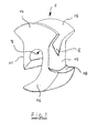
- FIG. 1 shows in perspective a plastic molding 1, which is a spring bearing 2 for a spring eye 3 on a component or on a frame 4, such as in the FIG. 2 represented, a washing machine forms.
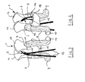
- the plastic molded part 1 comprises on the one hand a curved groove 5 for receiving the hook 6 formed as a spring eye 3, and on the other hand, a molded shaft support 7, preferably with a crank-like shaft 8, as shown in particular FIGS. 3 and 4 is shown, cooperates.
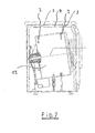
- the crank-like shaft 8 is with their lugs 9 and 10 on the frame 4 in the FIG. 2 pictured washing machine pivotally mounted.
- the groove 5 has a V-shaped profiling, wherein on the groove walls each ear segments 16 and 17 are integrally formed.
- a support surface 18 is formed for the hook ends of the spring lug 3 on the curved projection 15.
- FIG. 2 It can be seen that in particular on the frame 4, the spring eyes 3 are fixed, the spring eyes 3 are now equipped with the plastic molded part 1, which in turn with the crank-like shaft 8 in Active compound stand.
- the lugs 9 and 10 are pivotally mounted on the frame 4. If the drum 19 is now moved into an inclined position, as shown, the plastic moldings 1 according to the invention prevent wear and especially acoustic phenomena.
- the shaft support 7 shown in section has a narrowing of the diameter, so that a Klipsfunktion is to be realized.
- the plastic molded part 1 is mounted, in which the shaft 8 is guided through the recess, and the plastic molded part 1 is clipped onto the shaft 8 and thus held.
- the mounting aperture is configured to taper inwardly for ease of assembly.
- the mounting hole is not straight made for the reason.
- the straight legs of the crankshaft 8 thus encounter regardless of their position always in front of the front or back of the plastic molded part 1.
- the cross section the groove 5, in which the spring eye 3 is inserted must be designed so that a pivoting movement of the spring is allowed.
- a minimum radius of the cross section of the groove 5 corresponding to the wire thickness of the spring is required. Of course, this radius must grow to the sides.
- the ears 16 and 17 of the plastic molding on the one hand facilitate the assembly of the spring and prevent springing off of the spring in the event of shock, when no spring forces act more.
Landscapes
- Engineering & Computer Science (AREA)
- Textile Engineering (AREA)
- Springs (AREA)
Abstract
Description
Die Erfindung betrifft ein Federlager für eine Federöse einer Feder an einem Bauteil, Rahmen oder dergleichen.The invention relates to a spring bearing for a spring eye of a spring on a component, frame or the like.
Bei einem Federlager, und hier insbesondere im Ösenbereich der Feder, ergibt sich das Problem, dass die Federöse auf einem Bolzen oder einer Welle gelagert wird, wobei bei entsprechender Beanspruchung der Feder, auch unter einer Neigung, nicht nur im Lagerungspunkt Verschleißerscheinungen auftreten, sondern es treten hierbei auch akustische Erscheinungen auf.In a spring bearing, and here in particular in Ösenbereich the spring, there is the problem that the spring eye is mounted on a bolt or a shaft, with appropriate stress on the spring, even under a slope, not only wear in the bearing point, but it In this case also appear acoustic phenomena.
Aus der
Der Erfindung stellt sich somit das Problem, ein Federlager für eine Öse an einem Bauteil oder einem Rahmen derart weiter zu bilden, welches die beschriebenen Nachteile überwindet und hier insbesondere die Verschleißerscheinungen und/oder die Akustik-Erscheinungen im Lagerpunkt unterbindet.The invention thus raises the problem of further developing a spring bearing for an eyelet on a component or a frame in such a way that overcomes the described disadvantages and in particular prevents the signs of wear and / or the acoustic phenomena in the bearing point.
Erfindungsgemäß wird dieses Problem durch die Merkmale des Anspruchs 1 gelöst, vorteilhafte Ausgestaltungen und Weiterbildungen der Erfindung ergeben sich aus den nachfolgenden Unteransprüchen.According to the invention, this problem is solved by the features of claim 1, advantageous embodiments and modifications of the invention will become apparent from the following subclaims.
Das Federlager als solches wird gemäß der Erfindung aus einem Kunststoffformteil gebildet, in dem einerseits eine gebogene Nut zur Aufnahme der als Haken ausgebildeten Federöse vorgesehen ist, und wobei das Kunststoffformteil andererseits eine eingeformte Wellenauflage aufweist, die vorzugsweise mit einer kurbelartigen Welle zusammenwirkt, die wiederum an dem Bauteil schwenkbar gelagert ist. Das erfindungsgemäße Kunststoffformteil unterbindet somit einen Kontakt von Federöse zum Bauteil bzw. zum Rahmen an dem die Feder angebracht ist. Die erzwungene Schwenkbewegung bei einer Beanspruchung der Feder unter einer Neigung erfolgt gegenüber dem Bauteil oder dem Rahmen über die kurbelartige Welle, so dass die Reiberscheinungen auf eine Minimum beschränkt werden.The spring bearing as such is formed according to the invention of a plastic molding in which on the one hand a curved groove for receiving the hook formed as spring eye is provided, and wherein the plastic molded part on the other hand has a molded shaft support, which preferably cooperates with a crank-like shaft, in turn is pivotally mounted to the component. The plastic molding according to the invention thus prevents contact of spring eye to the component or to the frame on which the spring is mounted. The forced pivoting movement when the spring is subjected to an inclination against the component or the frame via the crank-like shaft, so that the friction phenomena are kept to a minimum.
Ein derartiges Federlager besitzt die hinreichenden Freiheitsgrade für eine Feder, die insbesondere bei Haushaltgeräten wie Waschautomaten zum Einsatz kommen. Das heißt, die Feder kann quer zu der Nut verschwenkt werden. Ein Verdrehen der Feder in Längsrichtung zur Nut ist nicht möglich. In diese Richtung wird durch die besondere Form des Kunststoffformteils eine Relativbewegung unterdrückt. Sollte eine solche Bewegung über die Feder erzwungen werden, findet die Relativbewegung zwischen der Welle und dem Bauteil statt.Such a spring bearing has the sufficient degrees of freedom for a spring, which are used in particular in household appliances such as washing machines. That is, the spring can be pivoted transversely to the groove. A twisting of the spring in the longitudinal direction of the groove is not possible. In this direction, a relative movement is suppressed by the special shape of the plastic molded part. Should such a movement be forced by the spring, the relative movement takes place between the shaft and the component.
Hierzu schließt zur Verdrehsicherung des Kunststoffformteils in der als Haken ausgebildeten Federöse sich zur einen Seite an die Nut eine Anlagefläche an, die entsprechend an den geraden Abschnitt der Federöse im eingesetzten Zustand ausgerichtet ist. Zur anderen Seite der Nut schließt sich eine Anlagefläche an, die entsprechend der Erstreckung der freien Haken ausgebildet ist. Somit wird quasi das Kunststoffformteil von der hakenförmigen Federöse eingefasst und es wird in einer Zwangslage gehalten.To this end, to prevent rotation of the plastic molded part in the form of a hook spring eyelet includes on one side to the groove a contact surface, which is aligned in accordance with the straight portion of the spring eye in the inserted state. To the other side of the groove is followed by a contact surface, which is formed according to the extension of the free hooks. Thus, the plastic molding is quasi edged by the hook-shaped spring eyelet and it is held in a predicament.
In vorteilhafter Weiterbildung schließt sich an die Anlagefläche für die Haken ein gebogener Ansatz an, der bis in die Ebene der Anlagefläche für den geraden Abschnitt der Federöse ragt. Somit ergibt sich einerseits ein Montageschlitz für die Wellenauflage, und andererseits eine zusätzliche Abstützung für die geraden Abschnitte der Federöse. Die Nut weist eine V-förmige Profilierung auf, wobei an den Nutwänden jeweils Ohrensegmente angeformt sind. In Weiterbildung der Erfindung sind an dem gebogenen Ansatz die Auflageflächen für die Hakenenden der Federöse angeformt.In an advantageous development, a curved projection adjoins the contact surface for the hook, which protrudes into the plane of the contact surface for the straight section of the spring eye. Thus, on the one hand results in a mounting slot for the shaft support, and on the other hand, an additional support for the straight portions of the spring eye. The groove has a V-shaped profiling, wherein on the groove walls each ear segments are formed. In a further development of the invention, the bearing surfaces for the hook ends of the spring eye are formed on the curved approach.
Ein Ausführungsbeispiel der Erfindung ist in den Zeichnungen rein schematisch dargestellt und wird nachfolgend näher beschrieben. Es zeigen:
- Figur 1:
- eine perspektivische Darstellung des erfindungsgemäßen Kunststoffformteils;
- Figur 2:
- eine geschnittene Seitenansicht eines Waschautomaten mit einer Neigevorrichtung für die Trommel; in der eine Einsatzmöglichkeit für das erfindungsgemäße Federlager gegeben ist;
- Figur 3:
- eine perspektivische Darstellung des Kunststoffformteils gemäß der
Figur 1 mit Kurbelwelle und eingebundener Federöse jeweils in zwei Positionen und - Figur 4:
- eine weitere perspektivische Darstellung in einer anderen Blickrichtung gemäß der
Figur 3
- FIG. 1:
- a perspective view of the plastic molding according to the invention;
- FIG. 2:
- a sectional side view of a washing machine with a tilting device for the drum; in which a possible use for the spring bearing according to the invention is given;
- FIG. 3:
- a perspective view of the plastic molding according to the
FIG. 1 with crankshaft and integrated spring eyelet in two positions and - FIG. 4:
- another perspective view in another direction according to the
FIG. 3 ,
Die
Um eine Verdrehsicherung zwischen der Federöse 3 und dem Kunststoffformteil 1 herzustellen, schließt sich zur einen Seite an die Nut 5 eine Anlagefläche 11 an, die entsprechend an den geraden Abschnitt 12 der Federöse 3 im eingesetzten Zustand, wie in der
Wie aus der
Wie aus der
Die
Zu den
Die Montageöffnung ist so ausgestaltet, dass sie sich zum Zwecke der einfachen Montage nach innen verjüngt. Bei der Montage des Kunststoffformteils 1 auf einer Kurbelwelle 8 bzw. gekröpften Welle muss sichergestellt werden, dass das Kunststoffformteil 1 beim Einwirken von Querkräften nicht von der Welle 8 gezogen werden kann. Die Montageöffnung ist aus dem Grunde nicht gerade ausgeführt. Die geraden Schenkel der Kurbelwelle 8 stoßen somit unabhängig von ihrer Stellung stets vor die Vorder- oder Rückseite des Kunststoffformteils 1. Der Querschnitt der Nut 5, in die die Federöse 3 eingelegt wird, muss so gestaltet sein, dass eine Schwenkbewegung der Feder zugelassen wird. In der Mitte der Öse 3 ist ein Mindestradius des Querschnittes der Nut 5 entsprechend der Drahtstärke der Feder erforderlich. Dieser Radius muss selbstverständlich zu den Seiten hin anwachsen. Die Ohren 16 und 17 des Kunststoffformteils erleichtern zum einen die Montage der Feder und verhindern ein Abspringen der Feder im Stoßfall, wenn keine Federkräfte mehr wirken.The mounting aperture is configured to taper inwardly for ease of assembly. When mounting the plastic molded part 1 on a crankshaft 8 or cranked shaft must be ensured that the plastic molded part 1 can not be pulled by the shaft 8 when acting on lateral forces. The mounting hole is not straight made for the reason. The straight legs of the crankshaft 8 thus encounter regardless of their position always in front of the front or back of the plastic molded part 1. The cross section the
Claims (6)
- Spring bearing for a spring lug of a spring on a component, frame or the like, the said spring bearing including a plastics material moulded part (1), on the one side of which there is provided a curved groove (5) for accommodating the spring lug (3) that is in the form of hook (6), characterised in that the other side of the plastics material moulded part (1) includes a moulded shaft support (7), which interacts with a crank-like shaft (8), wherein the said crank-like shaft (8) is mounted in its turn so as to be pivotable on the component or frame (4).
- Spring bearing according to claim 1, characterised in that a contact face (11) connects to the groove (5) on one side for securing the plastics material moulded part (4) in a non-rotatable manner in the spring lug (3) that is in the form of hook (6), the said contact face (11) being orientated corresponding to the straight portion (12) of the spring lug (3).
- Spring bearing according to claim 2, characterised in that an additional contact face (13) connects on the other side of the groove (5), the said additional contact face being orientated corresponding to the free ends (14) of the hook (6).
- Spring bearing according to claim 3, characterised in that a curved shoulder (15) connects to the contact face (13) for the hook (6), the said curved shoulder (15) extending as far as into the plane of the contact surface (11) for the straight portion (12) of the spring lug (3).
- Spring bearing according to claims 1 to 4, characterised in that the groove (5) has a V-shaped profile, wherein ear segments (16) and (17) are integrally formed on each of the groove walls.
- Spring bearing according to claims 1 to 5, characterised in that a contact surface (18) for the hook ends of the spring lug (3) is integrally moulded on the curved shoulder (15).
Applications Claiming Priority (2)
| Application Number | Priority Date | Filing Date | Title |
|---|---|---|---|
| DE102004019902 | 2004-04-21 | ||
| DE102004019902A DE102004019902B3 (en) | 2004-04-21 | 2004-04-21 | Spring bearing for a spring eye of a spring on a component or frame |
Publications (3)
| Publication Number | Publication Date |
|---|---|
| EP1589142A2 EP1589142A2 (en) | 2005-10-26 |
| EP1589142A3 EP1589142A3 (en) | 2006-08-16 |
| EP1589142B1 true EP1589142B1 (en) | 2008-10-01 |
Family
ID=34934794
Family Applications (1)
| Application Number | Title | Priority Date | Filing Date |
|---|---|---|---|
| EP05007498A Expired - Lifetime EP1589142B1 (en) | 2004-04-21 | 2005-04-06 | Spring support for a spring eyelet on a part, a frame or similar |
Country Status (3)
| Country | Link |
|---|---|
| EP (1) | EP1589142B1 (en) |
| AT (1) | ATE409773T1 (en) |
| DE (2) | DE102004019902B3 (en) |
Families Citing this family (2)
| Publication number | Priority date | Publication date | Assignee | Title |
|---|---|---|---|---|
| US4834735A (en) * | 1986-07-18 | 1989-05-30 | The Proctor & Gamble Company | High density absorbent members having lower density and lower basis weight acquisition zones |
| US9297104B2 (en) * | 2012-01-25 | 2016-03-29 | Illinois Tool Works Inc. | Washing machine suspension ball support |
Family Cites Families (5)
| Publication number | Priority date | Publication date | Assignee | Title |
|---|---|---|---|---|
| DE6752636U (en) * | 1968-06-06 | 1969-03-27 | Siemens Electrogeraete | SPRING BEARING FOR THE TENSION SPRINGS HOLDING THE DRUM UNIT OF A WASHING MACHINE. |
| JPS5488668A (en) * | 1977-12-24 | 1979-07-13 | Matsushita Electric Ind Co Ltd | Single-tank washer |
| JPS58261A (en) * | 1981-06-23 | 1983-01-05 | Matsushita Electric Ind Co Ltd | Washing machine dehydration receiver support device |
| JPH04189397A (en) * | 1990-11-22 | 1992-07-07 | Matsushita Electric Ind Co Ltd | Electric washing machine vibration isolator |
| DE9405703U1 (en) * | 1994-04-06 | 1994-05-26 | Texmato GmbH & Co, 49090 Osnabrück | Device for fastening wave springs to frame struts |
-
2004
- 2004-04-21 DE DE102004019902A patent/DE102004019902B3/en not_active Expired - Fee Related
-
2005
- 2005-04-06 EP EP05007498A patent/EP1589142B1/en not_active Expired - Lifetime
- 2005-04-06 AT AT05007498T patent/ATE409773T1/en not_active IP Right Cessation
- 2005-04-06 DE DE502005005500T patent/DE502005005500D1/en not_active Expired - Lifetime
Also Published As
| Publication number | Publication date |
|---|---|
| EP1589142A2 (en) | 2005-10-26 |
| DE102004019902B3 (en) | 2005-12-01 |
| DE502005005500D1 (en) | 2008-11-13 |
| ATE409773T1 (en) | 2008-10-15 |
| EP1589142A3 (en) | 2006-08-16 |
Similar Documents
| Publication | Publication Date | Title |
|---|---|---|
| EP2250944B1 (en) | Spring core element for use in a mattress, for example pocket spring core mattress | |
| AT510436B1 (en) | SNAP HOOK | |
| DE4421878A1 (en) | Oscillation damping attachment for motor vehicle windscreen wiper | |
| EP3033538B1 (en) | Lining retaining spring for a brake lining and brake lining retainer for a disc brake on a motor vehicle | |
| WO2013091792A1 (en) | Spindle drive for an adjustment element of a motor vehicle | |
| DE102005026471B4 (en) | Holder for a wire in an automobile | |
| DE102008007107A1 (en) | Axial ball joint with stop damping | |
| DE102013101781A1 (en) | Brake pad holder for a disc brake of a motor vehicle | |
| DE2830096A1 (en) | ELASTIC CLAMP FOR RODS WITH VARIABLE DIAMETERS | |
| DE2451084B2 (en) | BALL JOINT | |
| DE102012208084B3 (en) | An articulating device for connecting a friction damper to a washing machine | |
| EP1589142B1 (en) | Spring support for a spring eyelet on a part, a frame or similar | |
| EP1431641B1 (en) | Pipe clamp | |
| EP2045405B1 (en) | Actuating plate for an actuating device of a rinsing facility | |
| EP2088228A1 (en) | Latch needle | |
| DE20309732U1 (en) | Ventilation nozzle for a vehicle consists of a housing, an outlet opening and swivelable slats mounted in end bearings | |
| EP3010735A1 (en) | Torsion spring element | |
| EP2167354B1 (en) | Fastening arrangement | |
| DE102011000339A9 (en) | Handle of a motor vehicle | |
| EP1752577B1 (en) | Washing machine with mountings for the suspension of an oscillating unit | |
| DE102012209058A1 (en) | Windscreen wiper device for motor car, has aperture whose internal diameter is slightly smaller than outer diameter of assembly region of socket pad such that pad is attached into device by simply inserting and clipping pad into opening | |
| EP1741820A1 (en) | Washing machine with a transport securing device | |
| DE102009000461A1 (en) | Cylinder head cover for covering cylinder head of common rail injection system in e.g. engine, has holders provided for receiving conduits, where holders are designed as common injection molding parts that are integrally formed with cover | |
| EP1799897B1 (en) | Pivot bearing for a loom and loom comprising a pivot bearing | |
| EP4139586B1 (en) | Cable-guiding apparatus, in particular an energy chain, and chain link with damping elements |
Legal Events
| Date | Code | Title | Description |
|---|---|---|---|
| PUAI | Public reference made under article 153(3) epc to a published international application that has entered the european phase |
Free format text: ORIGINAL CODE: 0009012 |
|
| AK | Designated contracting states |
Kind code of ref document: A2 Designated state(s): AT BE BG CH CY CZ DE DK EE ES FI FR GB GR HU IE IS IT LI LT LU MC NL PL PT RO SE SI SK TR |
|
| AX | Request for extension of the european patent |
Extension state: AL BA HR LV MK YU |
|
| PUAL | Search report despatched |
Free format text: ORIGINAL CODE: 0009013 |
|
| AK | Designated contracting states |
Kind code of ref document: A3 Designated state(s): AT BE BG CH CY CZ DE DK EE ES FI FR GB GR HU IE IS IT LI LT LU MC NL PL PT RO SE SI SK TR |
|
| AX | Request for extension of the european patent |
Extension state: AL BA HR LV MK YU |
|
| 17P | Request for examination filed |
Effective date: 20070111 |
|
| AKX | Designation fees paid |
Designated state(s): AT BE BG CH CY CZ DE DK EE ES FI FR GB GR HU IE IS IT LI LT LU MC NL PL PT RO SE SI SK TR |
|
| 17Q | First examination report despatched |
Effective date: 20070503 |
|
| GRAP | Despatch of communication of intention to grant a patent |
Free format text: ORIGINAL CODE: EPIDOSNIGR1 |
|
| GRAS | Grant fee paid |
Free format text: ORIGINAL CODE: EPIDOSNIGR3 |
|
| GRAA | (expected) grant |
Free format text: ORIGINAL CODE: 0009210 |
|
| AK | Designated contracting states |
Kind code of ref document: B1 Designated state(s): AT BE BG CH CY CZ DE DK EE ES FI FR GB GR HU IE IS IT LI LT LU MC NL PL PT RO SE SI SK TR |
|
| REG | Reference to a national code |
Ref country code: GB Ref legal event code: FG4D Free format text: NOT ENGLISH |
|
| REG | Reference to a national code |
Ref country code: CH Ref legal event code: EP |
|
| REG | Reference to a national code |
Ref country code: IE Ref legal event code: FG4D Free format text: LANGUAGE OF EP DOCUMENT: GERMAN |
|
| REF | Corresponds to: |
Ref document number: 502005005500 Country of ref document: DE Date of ref document: 20081113 Kind code of ref document: P |
|
| REG | Reference to a national code |
Ref country code: GB Ref legal event code: 746 Effective date: 20081104 |
|
| PG25 | Lapsed in a contracting state [announced via postgrant information from national office to epo] |
Ref country code: SI Free format text: LAPSE BECAUSE OF FAILURE TO SUBMIT A TRANSLATION OF THE DESCRIPTION OR TO PAY THE FEE WITHIN THE PRESCRIBED TIME-LIMIT Effective date: 20081001 |
|
| NLV1 | Nl: lapsed or annulled due to failure to fulfill the requirements of art. 29p and 29m of the patents act | ||
| REG | Reference to a national code |
Ref country code: IE Ref legal event code: FD4D |
|
| PG25 | Lapsed in a contracting state [announced via postgrant information from national office to epo] |
Ref country code: BG Free format text: LAPSE BECAUSE OF FAILURE TO SUBMIT A TRANSLATION OF THE DESCRIPTION OR TO PAY THE FEE WITHIN THE PRESCRIBED TIME-LIMIT Effective date: 20090101 Ref country code: LT Free format text: LAPSE BECAUSE OF FAILURE TO SUBMIT A TRANSLATION OF THE DESCRIPTION OR TO PAY THE FEE WITHIN THE PRESCRIBED TIME-LIMIT Effective date: 20081001 Ref country code: ES Free format text: LAPSE BECAUSE OF FAILURE TO SUBMIT A TRANSLATION OF THE DESCRIPTION OR TO PAY THE FEE WITHIN THE PRESCRIBED TIME-LIMIT Effective date: 20090112 |
|
| PG25 | Lapsed in a contracting state [announced via postgrant information from national office to epo] |
Ref country code: IS Free format text: LAPSE BECAUSE OF FAILURE TO SUBMIT A TRANSLATION OF THE DESCRIPTION OR TO PAY THE FEE WITHIN THE PRESCRIBED TIME-LIMIT Effective date: 20090201 Ref country code: PL Free format text: LAPSE BECAUSE OF FAILURE TO SUBMIT A TRANSLATION OF THE DESCRIPTION OR TO PAY THE FEE WITHIN THE PRESCRIBED TIME-LIMIT Effective date: 20081001 Ref country code: PT Free format text: LAPSE BECAUSE OF FAILURE TO SUBMIT A TRANSLATION OF THE DESCRIPTION OR TO PAY THE FEE WITHIN THE PRESCRIBED TIME-LIMIT Effective date: 20090302 Ref country code: NL Free format text: LAPSE BECAUSE OF FAILURE TO SUBMIT A TRANSLATION OF THE DESCRIPTION OR TO PAY THE FEE WITHIN THE PRESCRIBED TIME-LIMIT Effective date: 20081001 Ref country code: FI Free format text: LAPSE BECAUSE OF FAILURE TO SUBMIT A TRANSLATION OF THE DESCRIPTION OR TO PAY THE FEE WITHIN THE PRESCRIBED TIME-LIMIT Effective date: 20081001 |
|
| PG25 | Lapsed in a contracting state [announced via postgrant information from national office to epo] |
Ref country code: EE Free format text: LAPSE BECAUSE OF FAILURE TO SUBMIT A TRANSLATION OF THE DESCRIPTION OR TO PAY THE FEE WITHIN THE PRESCRIBED TIME-LIMIT Effective date: 20081001 Ref country code: DK Free format text: LAPSE BECAUSE OF FAILURE TO SUBMIT A TRANSLATION OF THE DESCRIPTION OR TO PAY THE FEE WITHIN THE PRESCRIBED TIME-LIMIT Effective date: 20081001 Ref country code: IE Free format text: LAPSE BECAUSE OF FAILURE TO SUBMIT A TRANSLATION OF THE DESCRIPTION OR TO PAY THE FEE WITHIN THE PRESCRIBED TIME-LIMIT Effective date: 20081001 Ref country code: RO Free format text: LAPSE BECAUSE OF FAILURE TO SUBMIT A TRANSLATION OF THE DESCRIPTION OR TO PAY THE FEE WITHIN THE PRESCRIBED TIME-LIMIT Effective date: 20081001 |
|
| PLBE | No opposition filed within time limit |
Free format text: ORIGINAL CODE: 0009261 |
|
| STAA | Information on the status of an ep patent application or granted ep patent |
Free format text: STATUS: NO OPPOSITION FILED WITHIN TIME LIMIT |
|
| PG25 | Lapsed in a contracting state [announced via postgrant information from national office to epo] |
Ref country code: SE Free format text: LAPSE BECAUSE OF FAILURE TO SUBMIT A TRANSLATION OF THE DESCRIPTION OR TO PAY THE FEE WITHIN THE PRESCRIBED TIME-LIMIT Effective date: 20090101 Ref country code: CZ Free format text: LAPSE BECAUSE OF FAILURE TO SUBMIT A TRANSLATION OF THE DESCRIPTION OR TO PAY THE FEE WITHIN THE PRESCRIBED TIME-LIMIT Effective date: 20081001 |
|
| 26N | No opposition filed |
Effective date: 20090702 |
|
| PG25 | Lapsed in a contracting state [announced via postgrant information from national office to epo] |
Ref country code: SK Free format text: LAPSE BECAUSE OF FAILURE TO SUBMIT A TRANSLATION OF THE DESCRIPTION OR TO PAY THE FEE WITHIN THE PRESCRIBED TIME-LIMIT Effective date: 20081001 |
|
| BERE | Be: lapsed |
Owner name: MIELE & CIE. K.G. Effective date: 20090430 |
|
| REG | Reference to a national code |
Ref country code: CH Ref legal event code: PL |
|
| PG25 | Lapsed in a contracting state [announced via postgrant information from national office to epo] |
Ref country code: LI Free format text: LAPSE BECAUSE OF NON-PAYMENT OF DUE FEES Effective date: 20090430 Ref country code: CH Free format text: LAPSE BECAUSE OF NON-PAYMENT OF DUE FEES Effective date: 20090430 |
|
| PG25 | Lapsed in a contracting state [announced via postgrant information from national office to epo] |
Ref country code: MC Free format text: LAPSE BECAUSE OF NON-PAYMENT OF DUE FEES Effective date: 20090430 |
|
| PG25 | Lapsed in a contracting state [announced via postgrant information from national office to epo] |
Ref country code: BE Free format text: LAPSE BECAUSE OF NON-PAYMENT OF DUE FEES Effective date: 20090430 |
|
| PG25 | Lapsed in a contracting state [announced via postgrant information from national office to epo] |
Ref country code: AT Free format text: LAPSE BECAUSE OF NON-PAYMENT OF DUE FEES Effective date: 20090406 |
|
| PG25 | Lapsed in a contracting state [announced via postgrant information from national office to epo] |
Ref country code: GR Free format text: LAPSE BECAUSE OF FAILURE TO SUBMIT A TRANSLATION OF THE DESCRIPTION OR TO PAY THE FEE WITHIN THE PRESCRIBED TIME-LIMIT Effective date: 20090102 |
|
| PG25 | Lapsed in a contracting state [announced via postgrant information from national office to epo] |
Ref country code: LU Free format text: LAPSE BECAUSE OF NON-PAYMENT OF DUE FEES Effective date: 20090406 |
|
| PG25 | Lapsed in a contracting state [announced via postgrant information from national office to epo] |
Ref country code: HU Free format text: LAPSE BECAUSE OF FAILURE TO SUBMIT A TRANSLATION OF THE DESCRIPTION OR TO PAY THE FEE WITHIN THE PRESCRIBED TIME-LIMIT Effective date: 20090402 |
|
| PG25 | Lapsed in a contracting state [announced via postgrant information from national office to epo] |
Ref country code: TR Free format text: LAPSE BECAUSE OF FAILURE TO SUBMIT A TRANSLATION OF THE DESCRIPTION OR TO PAY THE FEE WITHIN THE PRESCRIBED TIME-LIMIT Effective date: 20081001 |
|
| PG25 | Lapsed in a contracting state [announced via postgrant information from national office to epo] |
Ref country code: CY Free format text: LAPSE BECAUSE OF FAILURE TO SUBMIT A TRANSLATION OF THE DESCRIPTION OR TO PAY THE FEE WITHIN THE PRESCRIBED TIME-LIMIT Effective date: 20081001 |
|
| REG | Reference to a national code |
Ref country code: FR Ref legal event code: PLFP Year of fee payment: 11 |
|
| PGFP | Annual fee paid to national office [announced via postgrant information from national office to epo] |
Ref country code: GB Payment date: 20150423 Year of fee payment: 11 Ref country code: DE Payment date: 20150430 Year of fee payment: 11 |
|
| PGFP | Annual fee paid to national office [announced via postgrant information from national office to epo] |
Ref country code: FR Payment date: 20150422 Year of fee payment: 11 Ref country code: IT Payment date: 20150427 Year of fee payment: 11 |
|
| REG | Reference to a national code |
Ref country code: DE Ref legal event code: R119 Ref document number: 502005005500 Country of ref document: DE |
|
| GBPC | Gb: european patent ceased through non-payment of renewal fee |
Effective date: 20160406 |
|
| REG | Reference to a national code |
Ref country code: FR Ref legal event code: ST Effective date: 20161230 |
|
| PG25 | Lapsed in a contracting state [announced via postgrant information from national office to epo] |
Ref country code: DE Free format text: LAPSE BECAUSE OF NON-PAYMENT OF DUE FEES Effective date: 20161101 Ref country code: FR Free format text: LAPSE BECAUSE OF NON-PAYMENT OF DUE FEES Effective date: 20160502 Ref country code: GB Free format text: LAPSE BECAUSE OF NON-PAYMENT OF DUE FEES Effective date: 20160406 |
|
| PG25 | Lapsed in a contracting state [announced via postgrant information from national office to epo] |
Ref country code: IT Free format text: LAPSE BECAUSE OF NON-PAYMENT OF DUE FEES Effective date: 20160406 |